EP2425591B1 - Régulation d'inondation par paquets - Google Patents
Régulation d'inondation par paquets Download PDFInfo
- Publication number
- EP2425591B1 EP2425591B1 EP10715430.4A EP10715430A EP2425591B1 EP 2425591 B1 EP2425591 B1 EP 2425591B1 EP 10715430 A EP10715430 A EP 10715430A EP 2425591 B1 EP2425591 B1 EP 2425591B1
- Authority
- EP
- European Patent Office
- Prior art keywords
- label
- flow routing
- router
- frames
- flow
- Prior art date
- Legal status (The legal status is an assumption and is not a legal conclusion. Google has not performed a legal analysis and makes no representation as to the accuracy of the status listed.)
- Not-in-force
Links
- 238000012545 processing Methods 0.000 claims description 49
- 238000000034 method Methods 0.000 claims description 20
- 230000004044 response Effects 0.000 claims description 10
- 230000001419 dependent effect Effects 0.000 claims description 6
- 238000013459 approach Methods 0.000 description 7
- 230000002411 adverse Effects 0.000 description 4
- 238000005516 engineering process Methods 0.000 description 2
- 238000004891 communication Methods 0.000 description 1
- 238000004590 computer program Methods 0.000 description 1
- 238000013461 design Methods 0.000 description 1
- 238000012986 modification Methods 0.000 description 1
- 230000004048 modification Effects 0.000 description 1
- 230000010076 replication Effects 0.000 description 1
- 238000012552 review Methods 0.000 description 1
- 230000011664 signaling Effects 0.000 description 1
Images


Classifications
-
- H—ELECTRICITY
- H04—ELECTRIC COMMUNICATION TECHNIQUE
- H04L—TRANSMISSION OF DIGITAL INFORMATION, e.g. TELEGRAPHIC COMMUNICATION
- H04L45/00—Routing or path finding of packets in data switching networks
-
- H—ELECTRICITY
- H04—ELECTRIC COMMUNICATION TECHNIQUE
- H04L—TRANSMISSION OF DIGITAL INFORMATION, e.g. TELEGRAPHIC COMMUNICATION
- H04L12/00—Data switching networks
- H04L12/28—Data switching networks characterised by path configuration, e.g. LAN [Local Area Networks] or WAN [Wide Area Networks]
- H04L12/46—Interconnection of networks
- H04L12/4641—Virtual LANs, VLANs, e.g. virtual private networks [VPN]
-
- H—ELECTRICITY
- H04—ELECTRIC COMMUNICATION TECHNIQUE
- H04L—TRANSMISSION OF DIGITAL INFORMATION, e.g. TELEGRAPHIC COMMUNICATION
- H04L45/00—Routing or path finding of packets in data switching networks
- H04L45/50—Routing or path finding of packets in data switching networks using label swapping, e.g. multi-protocol label switch [MPLS]
Definitions
- the disclosures made herein relate generally to providing packet flood control in a network and, more particularly, to providing packet flood control at an egress edge router within a Multi-Protocol Label Switching domain of a network.
- packet flood control can be managed through a CML (i.e., CPU Managed Learning) register. Designated settings for this register allow packets to be dropped, send to CPU, or to flood out the packets.
- CML CPU Managed Learning
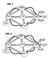
- the most desirable CML register setting for security purposes would be to drop all packets and not to flood out packets to other access port within the same VPLS domain. Unfortunately, because this setting is applied on a per port/virtual port basis, once this option is set, all packets destined for this unknown destination client will be dropped (as shown in FIG. 3 ).
- this includes packets from different sources (e.g., servers) even though they contain no sensitive information and even though it would be most desirable to allow traditional flooding for such packets from other sources within VPLS Service domain so that they can discover the destination and reestablish a flow path.
- sources e.g., servers
- LASSERRE M ET AL Virtual Private LAN Service (VPLS) Using Label Distribution Protocol (LDP) Signaling; rfc4762.txt” IEFT STANDARD, INTERNET ENGINEERING TASK FORCE, IETF, CH, 1 January 2007 (2007-01-01), XP015055051ISSN:0000-0003 ) describes a VPLS solution using pseudowires for Ethernet LAN technology, wherein forwarding of traffic in a MPLS network is implemented by packet replication across pseudowires for multicast/broadcast traffic and for flooding of unknown unicast destination traffic so that frames sent in particular to unknown destination MAC addresses are flooded to all ports.
- LDP Label Distribution Protocol
- Embodiments of packet flood control configured in accordance with the present invention provide for packet flood control in a manner that overcomes drawbacks associated with prior art approaches for providing packet flood control. For example, performing packet flood control in accordance with embodiments of the present invention allows packets destined for an unknown address on a PE router to be dropped on a per flow basis as opposed to a per port/virtual port basis. As such, embodiments of packet flood control configured in accordance with the present invention are advantageous, desirable and useful.
- a method comprises a plurality of operations.
- An egress router within a Multi-Protocol Label Switching (MPLS) domain performs an operation for receiving a plurality of different traffic flows.
- Each one of the traffic flow includes a plurality of frames each having a flow routing label and a destination address.
- Each one of the frames of a first one of the traffic flows and each one of the frames of a second one of the traffic flows have a common destination address.
- the egress router performs an operation for determining that the common destination address is unknown thereto and performs an operation for processing the flow routing label of each one of the frames.
- Such processing includes correlating a configuration of the flow routing label for each one of the frames to a respective one of the traffic flows.
- the egress router In response to such processing resulting in a determination that the flow routing label of a currently processed one of the frames corresponds to a first one of the traffic flows, the egress router performs an operation for causing the currently processed one of the frames to be dropped without flooding the currently processed one of the frames to all local access ports on an active Virtual Private LAN Service (VPLS) domain of the egress router. In response to such processing resulting in a determination that the flow routing label of a currently processed one of the frames corresponds to a second one of the traffic flows, the egress router performs an operation for causing the currently processed one of the frames to be flooded to all local access ports on the active VPLS domain of the egress router.
- VPLS Virtual Private LAN Service
- a network system comprises a first router having stored thereon a respective incoming label table including at least one set of Label Switching Path (LSP) information.
- the LSP information includes a LSP designator, a flow routing label denoting normal flow routing functionality and a flow routing label denoting controlled flow routing functionality.
- the first router is configured for receiving a plurality of different traffic flows each including a plurality of frames, for correlating a configuration of the flow routing label of each one of the frames received thereby to a respective one of the traffic flows using information contained in the incoming label table thereof, for flooding a frame of the traffic flows of the first router to all local access ports on an active virtual private LAN service (VPLS) domain thereof when the frame includes a flow routing label denoting normal flow routing functionality, and for dropping the frame without being flooded to all of the local access ports on the active VPLS domain when the frame includes a flow routing label denoting controlled flow routing functionality.
- VPLS virtual private LAN service
- a router comprises an ingress processing module, an egress processing module and a transit processing module.
- the ingress processing module includes a traffic flow data structure and a respective outgoing label table.
- the traffic flow data structure includes information therein that associates at least one source address with a respective type of flow routing functionality.
- the outgoing label table thereof includes at least one set of Label Switch Path (LSP) information.
- the LSP information includes a LSP designator, a flow routing label denoting normal flow routing functionality and a flow routing label denoting controlled flow routing functionality.
- the ingress processing module is configured for imposing a flow routing label on each frame received thereby from the at least one source address. Such imposing is performed dependent upon information contained in the traffic flow data structure and information contained in outgoing label table thereof.
- the egress processing module includes a respective incoming label table including at least one set of the LSP information.
- the egress processing module is configured for receiving a plurality of different traffic flows each including a plurality of frames, for correlating a configuration of the flow routing label of each one of the frames received thereby to a respective one of the traffic flows using information contained in the incoming label table thereof, for flooding a frame of the traffic flows of the egress processing module to be flooded to all local access ports on an active Virtual Private LAN Service (VPLS) domain thereof when the frame includes a flow routing label denoting normal flow routing functionality, and for causing the frame to be dropped without being flooded to all of the local access ports on the active VPLS domain when the frame includes a flow routing label denoting controlled flow routing functionality, wherein the egress processing module is configured for causing said dropping in response to determining that a destination address of the frame has become unknown thereto.
- VPLS Virtual Private LAN Service
- the transit processing module includes a respective incoming label table and a respective outgoing label table.
- the incoming and outgoing label tables of the transit processing module each include at least one set of the LSP information.
- the transit processing module is configured for receiving a plurality of different traffic flows each including a plurality of frames and for swapping the flow routing label of each one of the frames received thereby with a corresponding flow routing label within the outgoing label table thereof. Such swapping is performed dependent upon information contained in the inbound and outgoing label tables thereof.
- embodiments of the present invention provide for flow level (i.e., per flow) flood control thereby allowing flows containing certain information (e.g., sensitive information) to be protected (i.e., not flooded to potentially adverse destination addresses).
- flow level i.e., per flow
- packet flood control functionality in accordance with embodiments of the present invention can be used for other packet handing purposes as long as there are additional unused labels available.
- Multi-Protocol Label Switching is a packet-forwarding technology that uses labels to make data forwarding decisions.
- Each MPLS label is defined by a particular MPLS label value (e.g., currently MPLS label space has 20 bits with only a portion of such space for reserved labels).
- MPLS labels can be used to provide packet flood control through use of different types of flow routing functionalities. Such labels are referred to herein as flow routing labels. More specifically, through use of MPLS labels, embodiments of the present invention provide for flow level flood control such that sensitive information of a particular flow can be protected.
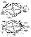
- FIG. 4 shows an embodiment of packet flood control in accordance with the present invention.
- Router 1 is connected to Server A and is functioning as an ingress Provider Edge (PE) router for traffic from the Server A.
- Router 5 is connected to the Client and Adversaries (i.e., adverse or potentially adverse clients with respect to the Client) and is functioning as an egress PE router for the Client and Adversaries.
- Routers 2-4 are connected between the ingress PE router and the egress PE router, and thus can each serve as a transit router with respect to the ingress and egress PE routers.
- a destination address (e.g., destination MAC address) becomes unknown to Router 5 for traffic flow from Server A (i.e., source address MAC "A")
- Server A i.e., source address MAC "A”
- all packets from Server A are will be dropped, while packets from other traffic flows (e.g., Server B) to the same destination address will be flooded as normal within current VPLS domain.
- Such flow routing functionality of dropping packets from one source address while flooding packets from a different source address can be achieved by using unique and normal labels for packet exchange among Label Edge Routers (i.e., Routers 1, 2, 4 and 5) and Label Switch Routers (i.e., Router 3) within the MPLS domain.
- Label Edge Routers i.e., Routers 1, 2, 4 and 5
- Label Switch Routers i.e., Router 3
- a hardware (HW) forwarding engine on the egress PE router will check a flow routing label used in incoming frames (i.e., of packets received thereby). If the flow routing labels denote that the traffic flow requires normal flow routing functionality (i.e., a normal flow routing label), the HW forwarding engine will strip off the normal flow routing labels of each frame and flood each packet as usual. If the flow routing labels denote that the traffic flow requires controlled flow routing functionality (i.e., a controlled flow routing label), the HW forwarding engine will drop the frames without performing any such flooding of corresponding packets. In this manner, packet flood control on a per-flow basis is provided.
- HW hardware
- LDP Label Distribution Protocol
- LSP Label Switching Path
- Each label table includes a plurality of respective LSP designators (e.g., LSP 1-2) and a LSP label associated with each one of the LSP designators (e.g., label "1020" associated with LSP designator "LSP 1-2").
- LSP designators e.g., LSP 1-2
- LSP label associated with each one of the LSP designators
- each router will generally have an incoming label table and an outgoing label table associated therewith.
- each label table is reconfigured to include sets of LSP information configured in accordance with the preset invention. More specifically, each set of LSP information includes a LSP designator (e.g., LSP 1-2), a flow routing label denoting normal flow routing functionality (e.g., label "1020" denoting normal flow routing functionality for LSP designated as "LSP 1-2”) and a flow routing label denoting controlled flow routing functionality (e.g., label "1021" denoting controlled flow routing functionality for LSP designated as "LSP 1-2"). Accordingly, a flow routing label denoting normal flow routing functionality is referred to herein as a normal flow routing label and a flow routing label denoting controlled flow routing functionality is referred to herein as a controlled flow routing label.
- LSP designator e.g., LSP 1-2
- a flow routing label denoting normal flow routing functionality e.g., label "1020" denoting normal flow routing functionality for LSP designated as "LSP 1-2”
- the ingress PE router i.e., Router 1
- a routing functionality look-up table i.e., a traffic flow data structure
- the routing functionality look-up table has information therein that associates at least one source address with a respective type of flow routing functionality.
- Server A having source address (i.e., MAC address) of "MAC A" is connected to the ingress PE router.
- a HW element of the ingress PE router can create the routing functionality lookup table indicating that any incoming packets with a source address of "MAC A" will use the controlled flow routing label instead of the normal controlled flow routing label as setup by the LDP.
- the LDP will reconfigure each label table of each router in the MPLS network (i.e., Routers 2 through Router 5) to include a controlled flow routing label and a normal flow routing label for each LSP designator.
- the routing functionality look-up table can be provided only on the ingress PE router.
- the Client initiates a connection to Server A and to Server B.
- Server B has a source address of "MAC B”.
- Router 1 serves as the ingress PE router for Server A and Server B.
- Server A is a controlled flow traffic source and Server B is a normal flow traffic source.
- traffic from Server A can include sensitive information that must not be flooded out to the Adversaries of the Client.
- the HW forwarding engine of the Ingress PE router checks the routing functionality look-up table to determine what type of flow routing label should be imposed on the frames of the packets received from Server A and Server B.
- each frame received from Server A is imposed with a controlled flow routing label corresponding to the LSP on which the packets from Server A will be forwarded (i.e., controlled flow routing label of 1021) and each frame received from Server B is imposed with a normal flow routing label corresponding to the LSP on which the packets from Server B will be forwarded (i.e., normal flow routing label of 1020).
- the HW forwarding engine forwards the corresponding packet out to an appropriate LSP (i.e., in the embodiment, packets from Server A and Server B are forwarded out on LSP 1-2).
- the packets from Server A and Server B are ingress by Router 2 (i.e., the LSR) and a HW forwarding engine of the LSR swaps MPLS labels of the frames thereof as usual (i.e., in accordance with standard MPLS protocol).
- Router 2 i.e., the LSR
- the HW forwarding engine of the LSR checks the flow routing label of each incoming frame against the LSP information maintained in the incoming label table thereof and correlates the type of flow routing label to a corresponding type of flow routing label in the outgoing label table of the LSR for the LSP on which the corresponding packet will be forwarded.
- the label of the incoming frame is swapped with a normal flow routing label corresponding to the LSP on which the corresponding packet will be forwarded (i.e., normal flow routing label of 2050), and if the label is a controlled flow routing label, the label of the incoming frame is swapped with a controlled flow routing label corresponding to the LSP on which the corresponding packet will be forwarded (i.e., controlled flow routing label of 2051).
- a HW forwarding engine of the egress router pops all labels from the frames of the packets after the packets ingress at the egress PE router.
- the destination address of the Client is learned and stored in the Layer 2 (L2) table of the egress PE router after the labels are popped. Thereafter, the HW forwarding engine of the egress PE router will checks if the destination address of each packets is known to the L2 table. When the destination address is known to the egress PE router, each packet is then forwarded via unicasting to the client destination address.
- the egress PE router can jointly perform normal flow routing functionality and controlled flow routing functionality when the destination address of the Client is removed from egress PE (i.e., becomes unknown to the egress PE router) due to reasons such as, for example, link down, port down, or even by user explicit flush command.
- packets having frames with the normal flow routing label e.g., those from Server B
- packets having frames with the controlled flow routing label e.g., those from Server A
- packets having frames with the controlled flow routing label e.g., those from Server A
- embodiments of the present invention advantageously allow for packets to be dropped on a per flow basis as opposed to a per port/virtual port basis.
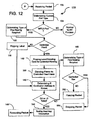
- the method 100 relies upon the use MPLS labels to provide packet flood control through use of different types of flow routing functionalities.
- the different flow routing functionalities provide for packet flood control to be provided on a per-flow basis as opposed to a per port/virtual port basis.
- the method 100 provides for flow level flood control such that sensitive information of a particular flow can be protected by not flooding it out to all local access ports within an active VPLS domain when a destination address of the particular traffic flow and other non-sensitive traffic flows become unknown to an egress router comprising the local access ports.
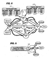
- an ingress router After an ingress router performs an operation 102 for receiving a packet from a source (e.g., a server), the ingress server performs an operation 104 for determining a current port type for a port on which the packet was received. In response to the port being a type other than a MPLS port, a normal VLAN process method proceeds for the packet. Otherwise, the port is an MPLS port and the ingress router performs an operation 106 for determining a type of flow routing functionality that the packet requires. In one embodiment, such determination is made by checking a lookup table that correlates a source address to a type of flow routing functionality.
- the ingress router When the determination is made that the packet requires normal flow routing functionality, the ingress router performs an operation 108 for imposing a normal flow routing label on each one of the frames of the packet. When the determination is made that the packet requires controlled flow routing functionality, the ingress router performs an operation 110 for imposing a controlled flow routing label on each one of the frames. Thereafter, the ingress router performs an operation 112 for finding next hop information for the packet and performs an operation 114 for forwarding the packet according to such next hop information.
- a transit router e.g., a label switching router (LSR)
- LSR label switching router
- the transit router then performs an operation 118 for processing a top of stack (TOS) label of each frame of the packet.
- TOS top of stack
- the transit router performs an operation 120 for popping the BOS label.
- the transit router performs an operation 122 for determining a type of flow routing functionality that the packet requires. In one embodiment, such determination is made by checking the flow routing label against flow routing labels in an incoming label table.
- the transit router When the determination is made that the packet requires normal flow routing functionality, the transit router performs an operation 124 for swapping the flow routing label of each frame with a corresponding normal flow routing label maintained in an outgoing label table of the transit router.
- the transit router performs an operation 126 for swapping the flow routing label of each frame with a corresponding controlled flow routing label maintained in the outgoing label table of the transit router. Thereafter, the transit router performs an operation 128 for finding next hop information for the packet and performs an operation 130 for forwarding the packet according to such next hop information.
- an egress router After the packet is forwarded by the transit router, an egress router performs an operation 132 for receiving the packet. After the egress router receives the packet, the egress router performs an operation 134 for determining a current port type for a port on which the packet was received. In response to the port being a type other than a MPLS port, a normal VLAN process method proceeds for the packet. Otherwise, the port is an MPLS port and the egress router performs an operation 136 for determining a type of flow routing functionality that the packet requires. In one embodiment, such determination is made by checking the flow routing label against flow routing labels in an incoming label table of the egress router.
- the egress router When the determination is made that the packet requires normal flow routing functionality (i.e., frames thereof include normal flow routing label), the egress router performs an operation 138 for popping the frame and performing an operation 140 for determining if a destination address of the packet is within a L2 table of the egress router.
- the egress router performs an operation 142 for popping the label and performs an operation 144 for denoting the packet as requiring controlled flow routing functionality.
- the method proceeds at the operation 140 for determining if the destination address of the packet is within the L2 table of the egress router.
- the egress router performs an operation 146 for finding next hop information for the packet and performs an operation 148 for forwarding (e.g., unicasting) the packet according to such next hop information. If the destination address of the packet is not within the L2 table of the egress router, the egress router performs an operation 150 for determining a type of flow routing functionality that the packet requires. When the determination is made that the packet requires normal flow routing functionality (i.e., frames thereof include normal flow routing label), the egress router performs an operation 152 for flooding the packet to all local access ports within an active VPLS domain of the egress router.
- normal flow routing functionality i.e., frames thereof include normal flow routing label
- the egress router When the determination is made that the packet requires controlled flow routing functionality (i.e., frames thereof include controlled flow routing label), the egress router performs an operation 154 for dropping the packet without flooding it to all local access ports within the active VPLS domain of the egress router.
- controlled flow routing functionality i.e., frames thereof include controlled flow routing label
- a router configured in accordance with an embodiment of the present invention can include an ingress processing module, an egress processing module and a transit processing module.
- the ingress processing module includes a traffic flow data structure and a respective outgoing label table.
- the traffic flow data structure includes information therein that associates at least one source address with a respective type of flow routing functionality.
- the outgoing label table thereof includes at least one set of Label Switch Path (LSP) information.
- LSP Label Switch Path
- the LSP information includes a LSP designator, a flow routing label denoting normal flow routing functionality and a flow routing label denoting controlled flow routing functionality.
- the ingress processing module is configured for imposing a flow routing label on each frame received thereby from the at least one source address. Such imposing is performed dependent upon information contained in the traffic flow data structure and information contained in outgoing label table thereof.
- the egress processing module includes a respective incoming label table including at least one set of the LSP information.
- the egress processing module is configured for receiving a plurality of different traffic flows each including a plurality of frames, for correlating a configuration of the flow routing label of each one of the frames received thereby to a respective one of the traffic flows using information contained in the incoming label table thereof, for flooding a frame of the traffic flows of the egress processing module to be flooded to all local access ports on an active Virtual Private LAN Service (VPLS) domain thereof when the frame includes a flow routing label denoting normal flow routing functionality, and for causing the frame to be dropped without being flooded to all of the local access ports on the active VPLS domain when the frame includes a flow routing label denoting controlled flow routing functionality, wherein the egress processing module is configured for causing said dropping in response to determining that a destination address of the frame has become unknown thereto.
- VPLS Virtual Private LAN Service
- the transit processing module includes a respective incoming label table and a respective outgoing label table.
- the incoming and outgoing label tables of the transit processing module each include at least one set of the LSP information.
- the transit processing module is configured for receiving a plurality of different traffic flows each including a plurality of frames and for swapping the flow routing label of each one of the frames received thereby with a corresponding flow routing label within the outgoing label table thereof. Such swapping is performed dependent upon information contained in the inbound and outgoing label tables thereof.
- a router configured in accordance with the present invention can include an ingress traffic interface, an egress traffic interface, memory, and one or more data processing devices (for example, processors ASICs, and/or the like).
- each one of a plurality of processing modules includes a respective one of the data processing devices.
- the ingress traffic interface is configured for being coupled to a network node (e.g., another router or a server) that forwards protocol data units (PDUs) such as, for example, packets to the router.
- PDUs protocol data units
- the egress traffic interface is configured for being coupled to a network node that receives protocol data units (PDUs) such as, for example, packets to the router.
- the memory has instructions stored thereon and accessible therefrom.
- the one or more processors are configured for accessing and interpreting the instructions thereby performing functionality defined by such instructions.
- the one or more processors are coupled to the interfaces for enabling communication between the one or more processors and network nodes connected to the interfaces.
- the instructions are configured for carrying out the method 100 discussed above such that for a given packet, the router performs a respective aspect of packet flood control as disclosed herein.
- instructions processible by a data processing device it will be understood from the disclosures made herein that methods, processes and/or operations adapted for carrying out packet flood control as disclosed herein are tangibly embodied by computer readable medium having instructions thereon that are configured for carrying out such functionality.
- the instructions are tangibly embodied for carrying out all or a portion of the method 100 and/or the functionality depicted in FIGS. 5-9 .
- the instructions may be accessible by one or more data processing devices from a memory apparatus (e.g. RAM, ROM, virtual memory, hard drive memory, etc), from an apparatus readable by a drive unit of a data processing system (e.g., a diskette, a compact disk, a tape cartridge, etc) or both.
- a memory apparatus e.g. RAM, ROM, virtual memory, hard drive memory, etc
- a drive unit of a data processing system e.g., a diskette, a compact disk, a tape cartridge, etc
- embodiments of computer readable medium in accordance with the present invention include a compact disk, a hard drive, RAM or other type of storage apparatus that has imaged thereon a computer program (i.e., instructions) adapted for carrying out packet flood control functionality in accordance with the present invention.
- a computer program i.e., instructions
Landscapes
- Engineering & Computer Science (AREA)
- Computer Networks & Wireless Communication (AREA)
- Signal Processing (AREA)
- Computer Security & Cryptography (AREA)
- Data Exchanges In Wide-Area Networks (AREA)
Claims (9)
- Procédé, comprenant :un routeur de sortie (405, 505) dans un domaine de commutation multiprotocole par étiquette, MPLS, (400, 500) recevant une pluralité de flux de trafic (410) différents, dans lequel chacun desdits flux de trafic (410) comprend une pluralité de trames présentant chacune une étiquette de routage de flux (511) et une adresse de destination, dans lequel chacune desdites trames d'un premier flux de trafic (901) parmi lesdits flux de trafic (410) et chacune desdites trames d'un deuxième flux de trafic (902) parmi lesdits flux de trafic (410) ont une adresse de destination commune ;le routeur de sortie (405, 505) déterminant que l'adresse de destination commune est inconnue de celui-ci ;le router de sortie (405, 505) traitant l'étiquette de routage de flux (511) de chacune desdites trames, dans lequel ledit traitement comprend la corrélation d'une configuration de l'étiquette de routage de flux (511) pour chacune desdites trames avec un flux de trafic respectif parmi lesdits flux de trafic (410) ;en réponse audit traitement résultant en une determination que l'étiquette de routage de flux d'une trame actuellement traitée parmi lesdites trames correspond à un premier flux de trafic (901) parmi lesdits flux de trafic (410), le routeur de sortie (405, 505) entraînant l'abandon de la trame actuellement traitée parmi lesdites trames sans que la trame actuellement traitée parmi lesdites trames soit propagée par inondation vers tous les ports d'accès locaux sur un domaine de service de réseau local privé virtuel, VPLS, actif du routeur de sortie (405, 505); eten réponse audit traitement résultant en une determination que l'étiquette de routage de flux d'une trame actuellement traitée parmi lesdites trames correspond à un deuxième flux de trafic (902) parmi lesdits flux de trafic (410), le routeur de sortie (405, 505) entraînant la propagation par inondation de la trame actuellement traitée parmi lesdites trames vers tous les ports d'accès locaux sur le domaine VPLS actif du routeur de sortie (405, 505).
- Procédé selon la revendication 1, comprenant en outre :un routeur d'entrée (401, 501) dans le domaine MPLS (400, 500) implosant l'étiquette de routage de flux (511) sur chacune desdites trames du premier flux de trafic (901) parmi lesdits flux de trafic (410) avant de transférer chacune desdites trames du premier flux de trafic (901) parmi lesdits flux de trafic (410) vers le routeur de sortie (405, 505).
- Procédé selon la revendication 2, comprenant en outre :le routeur d'entrée (601) conservant une structure de données de flux de trafic (610) contenant des informations qui associent une première adresse source (613) à un type de routage de flux (611) requis pour des trames indiquant la première adresse source (613), ladite imposition comprenant la détermination qu'une trame reçue par celui-ci indique la première adresse source (613) et la vérification de la structure de données de flux de trafic (610) pour identifier un type de routage de flux (611) qui correspond à la première adresse source (613).
- Procédé selon la revendication 3, comprenant en outre :le routeur d'entrée (601) et le routeur de sortie (605) conservant chacun une table respective d'étiquettes (615, 616) ;dans lequel chaque table d'étiquettes (615, 616) comprend au moins un ensemble d'informations de chemin à commutation d'étiquettes, LSP ;dans lequel lesdites informations LSP comprennent un indicateur LSP (617, 620), une étiquette de routage de flux (618, 621) indiquant une fonctionnalité de routage de flux normale et une étiquette de routage de flux (619, 622) indiquant une fonctionnalité de routage de flux régulés ;dans lequel ladite fonctionnalité de routage de flux normale consiste à entraîner la propagation par inondation de trames vers tous les ports d'accès locaux sur un domaine VPLS actif ; etladite fonctionnalité de routage de flux régulée consiste à entraîner l'abandon de trames sans qu'elles soient propagées par inondation vers tous les ports d'accès locaux sur un domaine VPLS actif.
- Procédé selon la revendication 4, comprenant en outre :un routeur de transit (502) couplé entre le routeur d'entrée (501) et le routeur de sortie (505) ;dans lequel le routeur de transit (502) conserve une table d'étiquettes d'entrée (512) et une table d'étiquettes de sortie (513) ; etdans lequel la table d'étiquettes d'entrée (512) et la table d'étiquettes de sortie (513) comprennent chacune au moins un ensemble d'informations LSP.
- Procédé selon la revendication 1, comprenant en outre :chaque routeur (601, 602, 603, 604, 605) dans le domaine MPLS (600) conservant une table respective d'étiquettes (615, 616);dans lequel chaque table d'étiquettes (615, 616) comprend au moins un ensemble d'informations de chemin à commutation d'étiquettes, LSP ;dans lequel lesdites informations LSP comprennent un indicateur LSP (617, 620), une étiquette de routage de flux (618, 621) indiquant une fonctionnalité de routage de flux normale et une étiquette de routage de flux (619, 622) indiquant une fonctionnalité de routage de flux régulée ;dans lequel ladite fonctionnalité de routage de flux normale consiste à entraîner la propagation par inondation de trames vers tous les ports d'accès locaux sur un domaine VPLS actif ; etladite fonctionnalité de routage de flux régulée consiste à entraîner l'abandon de trames sans qu'elles soient propagées par inondation vers tous les ports d'accès locaux sur un domaine VPLS actif.
- Routeur, comprenant :un module de traitement d'entrée comprenant une structure de données de flux de trafic et une table respective d'étiquettes de sortie (615), dans lequel la structure de données de flux de trafic contient des information qui associent au moins une adresse source (613, 614) à un type respectif (611, 612) de fonctionnalité de routage de flux et dans lequel la table d'étiquettes de sortie (615) de celui-ci comprend au moins un ensemble d'informations de chemin à commutation d'étiquettes, LSP, dans lequel lesdites information LSP comprennent un indicateur LSP (620), une étiquette de routage de flux (621) indiquant une fonctionnalité de routage de flux normale et une étiquette de routage de flux (622) indiquant une fonctionnalité de routage de flux régulée ; dans lequel le module de traitement d'entrée est configuré pour imposer une étiquette de routage de flux (621, 622) sur chaque trame reçue par celui-ci à partir de ladite au moins une adresse source (613, 614) et dans lequel ladite imposition est réalisée en fonction d'informations contenues dans la structure de données de flux de trafic et d'informations contenues dans la table d'étiquettes de sortie (615) de celui-ci ;un module de traitement de sortie comprenant une table respective d'étiquettes d'entrée (616), dans lequel la table d'étiquettes d'entrée (616) de celui-ci comprend au moins un ensemble desdites information LSP, dans lequel le module de traitement de sortie est configuré pour recevoir une pluralité de flux de trafic différents comprenant chacun une pluralité de trames, pour mettre en corrélation une configuration de l'étiquette de routage de flux de chacune desdites trames reçues par celui-ci avec un flux de trafic respectif parmi lesdits flux de trafic en utilisant des informations contenues dans la table d'étiquettes d'entrée de celui-ci, pour propager par inondation une trame desdits flux de trafic du module de traitement de sortie à propager par inondation vers tous les ports d'accès locaux sur un domaine de service de réseau local privé virtuel, VPLS, actif de celui-ci lorsque la trame comprend une étiquette de routage de flux (618) indiquant une fonctionnalité de routage de flux normale, et pour entraîner l'abandon de la trame sans qu'elle soit propagés par inondation vers tous lesdits ports d'accès locaux sur le domaine VPLS actif lorsque la trame comprend une étiquette de routage de flux (619) indiquant une fonctionnalité de routage de flux régulée, dans lequel le module de traitement de sortie est configuré pour entraîner ledit abandon en réponse à la determination qu'une adresse de destination de la trame est devenue inconnue de celui-ci ; etun module de traitement de transit comprenant une table respective d'étiquettes d'entrée (812) et une table respective d'étiquettes de sortie (813), dans lequel lesdites tables d'étiquettes d'entrée et de sortie comprennent chacune au moins un ensemble desdites informations LSP, dans lequel le module de traitement de transit est configuré pour recevoir une pluralité de flux de trafic différents comprenant chacun une pluralité de trames et pour échanger l'étiquette de routage de flux (814) de chacune desdites trames reçues par celui-ci avec une étiquette de routage de flux correspondante (815) dans la table d'étiquettes de sortie de celui-ci, et dans lequel ledit échange est réalisé en fonction d'informations contenues dans lesdites tables d'étiquettes d'entrée et de sortie (812, 813) de celui-ci.
- Routeur selon la revendication 7 dans lequel la structure de données de flux de trafic associe chaque adresse source (613, 614) pour le flux de trafic reçu par le deuxième routeur à ladite fonctionnalité de routage de flux normale (612) ou à ladite fonctionnalité de routage de flux régulée (611).
- Routeur selon la revendication 7 dans lequel chacune desdites tables d'étiquettes (615, 616, 812, 813):associe un premier indicateur LSP (617, 620, 816, 817) à une première étiquette de routage de flux indiquant une fonctionnalité de routage de flux normale (618, 621, 818, 819) et à une première étiquette de routage de flux indiquant une fonctionnalité de routage de flux régulée (619, 622, 820, 821); etassocie un deuxième indicateur LSP (617, 620, 816, 817) à une deuxième étiquette de routage de flux indiquant une fonctionnalité de routage de flux normale (618, 621, 818, 819) et à une deuxième étiquette de routage de flux indiquant une fonctionnalité de routage de flux régulée (619, 622, 820, 821).
Applications Claiming Priority (2)
| Application Number | Priority Date | Filing Date | Title |
|---|---|---|---|
| US12/387,401 US7990871B2 (en) | 2009-05-01 | 2009-05-01 | Packet flood control |
| PCT/US2010/031381 WO2010126724A1 (fr) | 2009-05-01 | 2010-04-16 | Régulation d'inondation par paquets |
Publications (2)
| Publication Number | Publication Date |
|---|---|
| EP2425591A1 EP2425591A1 (fr) | 2012-03-07 |
| EP2425591B1 true EP2425591B1 (fr) | 2013-06-05 |
Family
ID=42199906
Family Applications (1)
| Application Number | Title | Priority Date | Filing Date |
|---|---|---|---|
| EP10715430.4A Not-in-force EP2425591B1 (fr) | 2009-05-01 | 2010-04-16 | Régulation d'inondation par paquets |
Country Status (6)
| Country | Link |
|---|---|
| US (1) | US7990871B2 (fr) |
| EP (1) | EP2425591B1 (fr) |
| JP (1) | JP5275512B2 (fr) |
| KR (1) | KR101302410B1 (fr) |
| CN (1) | CN102415061B (fr) |
| WO (1) | WO2010126724A1 (fr) |
Families Citing this family (4)
| Publication number | Priority date | Publication date | Assignee | Title |
|---|---|---|---|---|
| JP5370017B2 (ja) * | 2009-06-15 | 2013-12-18 | 富士通株式会社 | 中継システム及び中継方法 |
| US8411689B2 (en) * | 2009-09-23 | 2013-04-02 | Aerovironment, Inc. | Fault-tolerant, frame-based communication system |
| US8411667B2 (en) | 2009-12-15 | 2013-04-02 | At&T Intellectual Property I, L.P. | Methods, apparatus and articles of manufacture to manipulate packet routing |
| WO2012110011A2 (fr) | 2011-02-19 | 2012-08-23 | Deutsche Telekom Ag | Boucles de trajets mpls au niveau réacheminement pour réseaux mpls sans connexion |
Family Cites Families (15)
| Publication number | Priority date | Publication date | Assignee | Title |
|---|---|---|---|---|
| JP4183379B2 (ja) * | 2000-11-27 | 2008-11-19 | 富士通株式会社 | ネットワーク及びエッジルータ |
| US7042841B2 (en) * | 2001-07-16 | 2006-05-09 | International Business Machines Corporation | Controlling network congestion using a biased packet discard policy for congestion control and encoded session packets: methods, systems, and program products |
| US7092357B1 (en) * | 2001-11-13 | 2006-08-15 | Verizon Services Corp. | Anti-flooding flow-control methods and apparatus |
| US7394756B1 (en) * | 2003-03-17 | 2008-07-01 | Sprint Communications Company L.P. | Secure hidden route in a data network |
| US20040223497A1 (en) * | 2003-05-08 | 2004-11-11 | Onvoy Inc. | Communications network with converged services |
| CN1294728C (zh) * | 2004-08-05 | 2007-01-10 | 华为技术有限公司 | 边缘路由器提供服务质量保证的方法及系统 |
| US8306023B2 (en) * | 2004-12-20 | 2012-11-06 | Hewlett-Packard Development Company, L.P. | Smuggling and recovery of non-packet information |
| US7688832B2 (en) * | 2005-01-28 | 2010-03-30 | Cisco Technology, Inc. | MPLS cookie label |
| US9185036B2 (en) * | 2005-03-23 | 2015-11-10 | Alcatel Lucent | Method and apparatus for flow control of data in a network |
| US7673068B2 (en) * | 2005-04-18 | 2010-03-02 | Alcatel Lucent | Method and system for implementing a high availability VLAN |
| US7808979B2 (en) * | 2006-06-26 | 2010-10-05 | Ciena Corporation | Methods and systems for packet aggregation combining connection-oriented and connection-less techniques |
| US20080181102A1 (en) * | 2007-01-25 | 2008-07-31 | Verizon Services Organization Inc. | Network routing |
| JP4899959B2 (ja) * | 2007-03-19 | 2012-03-21 | 富士通株式会社 | Vpn装置 |
| US7873042B2 (en) * | 2007-12-21 | 2011-01-18 | Sprint Communications Company L.P. | Multi-layered packet security |
| JP5119184B2 (ja) * | 2009-03-03 | 2013-01-16 | 富士通株式会社 | 中継装置、端末装置及び秘密通信システム |
-
2009
- 2009-05-01 US US12/387,401 patent/US7990871B2/en not_active Expired - Fee Related
-
2010
- 2010-04-16 CN CN201080019213.9A patent/CN102415061B/zh not_active Expired - Fee Related
- 2010-04-16 WO PCT/US2010/031381 patent/WO2010126724A1/fr not_active Ceased
- 2010-04-16 JP JP2012508525A patent/JP5275512B2/ja not_active Expired - Fee Related
- 2010-04-16 KR KR1020117025935A patent/KR101302410B1/ko not_active Expired - Fee Related
- 2010-04-16 EP EP10715430.4A patent/EP2425591B1/fr not_active Not-in-force
Also Published As
| Publication number | Publication date |
|---|---|
| WO2010126724A1 (fr) | 2010-11-04 |
| CN102415061B (zh) | 2014-10-08 |
| JP2012525772A (ja) | 2012-10-22 |
| KR101302410B1 (ko) | 2013-09-16 |
| CN102415061A (zh) | 2012-04-11 |
| US7990871B2 (en) | 2011-08-02 |
| US20100278044A1 (en) | 2010-11-04 |
| EP2425591A1 (fr) | 2012-03-07 |
| KR20120018137A (ko) | 2012-02-29 |
| JP5275512B2 (ja) | 2013-08-28 |
Similar Documents
| Publication | Publication Date | Title |
|---|---|---|
| US11296908B2 (en) | Using multiple ethernet virtual private network (EVPN) routes for corresponding service interfaces of a subscriber interface | |
| US10693679B2 (en) | Using multiple ethernet virtual private network (EVPN) routes for corresponding service interfaces of a subscriber interface | |
| CN110324226B (zh) | 改进以太虚拟专用网网络中多宿主站点流量的混叠行为 | |
| US9634929B2 (en) | Using context labels to scale MAC tables on computer network edge devices | |
| US7221675B2 (en) | Address resolution method for a virtual private network, and customer edge device for implementing the method | |
| CN102195865B (zh) | 多宿网络中的通信网络路径和状态信息 | |
| US20030026271A1 (en) | L2/L3 network with LSP-enabled virtual routing | |
| US11184276B1 (en) | EVPN signaling using segment routing | |
| US9178816B1 (en) | Control plane messaging in all-active multi-homed ethernet virtual private networks | |
| US20030223406A1 (en) | Methods and systems for a distributed provider edge | |
| CN109691026B (zh) | 更新多个多协议标签切换双向转发检测会话的方法和装置 | |
| CN105743689A (zh) | 对多宿主以太网虚拟专网中的链路故障的快速收敛 | |
| US20070242667A1 (en) | System and method for choosing an outgoing path for a media flow in a next generation network | |
| JP5795008B2 (ja) | ファストlspアラートメカニズム | |
| US20110176544A1 (en) | Link aggregation flood control | |
| EP2425591B1 (fr) | Régulation d'inondation par paquets | |
| JP2004247858A (ja) | 情報提供システム及び情報提供方法 | |
| Deelen et al. | Improving scalability of the AMS-IX network |
Legal Events
| Date | Code | Title | Description |
|---|---|---|---|
| PUAI | Public reference made under article 153(3) epc to a published international application that has entered the european phase |
Free format text: ORIGINAL CODE: 0009012 |
|
| 17P | Request for examination filed |
Effective date: 20111110 |
|
| AK | Designated contracting states |
Kind code of ref document: A1 Designated state(s): AT BE BG CH CY CZ DE DK EE ES FI FR GB GR HR HU IE IS IT LI LT LU LV MC MK MT NL NO PL PT RO SE SI SK SM TR |
|
| DAX | Request for extension of the european patent (deleted) | ||
| REG | Reference to a national code |
Ref country code: DE Ref legal event code: R079 Ref document number: 602010007619 Country of ref document: DE Free format text: PREVIOUS MAIN CLASS: H04L0012560000 Ipc: H04L0012460000 |
|
| GRAP | Despatch of communication of intention to grant a patent |
Free format text: ORIGINAL CODE: EPIDOSNIGR1 |
|
| RIC1 | Information provided on ipc code assigned before grant |
Ipc: H04L 12/773 20130101ALI20121203BHEP Ipc: H04L 12/46 20060101AFI20121203BHEP |
|
| GRAS | Grant fee paid |
Free format text: ORIGINAL CODE: EPIDOSNIGR3 |
|
| GRAA | (expected) grant |
Free format text: ORIGINAL CODE: 0009210 |
|
| AK | Designated contracting states |
Kind code of ref document: B1 Designated state(s): AT BE BG CH CY CZ DE DK EE ES FI FR GB GR HR HU IE IS IT LI LT LU LV MC MK MT NL NO PL PT RO SE SI SK SM TR |
|
| REG | Reference to a national code |
Ref country code: GB Ref legal event code: FG4D |
|
| REG | Reference to a national code |
Ref country code: CH Ref legal event code: EP |
|
| REG | Reference to a national code |
Ref country code: AT Ref legal event code: REF Ref document number: 616209 Country of ref document: AT Kind code of ref document: T Effective date: 20130615 |
|
| REG | Reference to a national code |
Ref country code: IE Ref legal event code: FG4D |
|
| REG | Reference to a national code |
Ref country code: DE Ref legal event code: R096 Ref document number: 602010007619 Country of ref document: DE Effective date: 20130801 |
|
| REG | Reference to a national code |
Ref country code: FR Ref legal event code: GC Effective date: 20130802 |
|
| 111Z | Information provided on other rights and legal means of execution |
Free format text: AT BE BG CH CY CZ DE DK EE ES FI FR GB GR HR HU IE IS IT LI LT LU LV MC MK MT NL NO PL PT RO SE SI SK SM TR Effective date: 20130410 |
|
| REG | Reference to a national code |
Ref country code: AT Ref legal event code: MK05 Ref document number: 616209 Country of ref document: AT Kind code of ref document: T Effective date: 20130605 |
|
| REG | Reference to a national code |
Ref country code: GB Ref legal event code: 732E Free format text: REGISTERED BETWEEN 20130919 AND 20130925 |
|
| PG25 | Lapsed in a contracting state [announced via postgrant information from national office to epo] |
Ref country code: GR Free format text: LAPSE BECAUSE OF FAILURE TO SUBMIT A TRANSLATION OF THE DESCRIPTION OR TO PAY THE FEE WITHIN THE PRESCRIBED TIME-LIMIT Effective date: 20130906 Ref country code: ES Free format text: LAPSE BECAUSE OF FAILURE TO SUBMIT A TRANSLATION OF THE DESCRIPTION OR TO PAY THE FEE WITHIN THE PRESCRIBED TIME-LIMIT Effective date: 20130916 Ref country code: LT Free format text: LAPSE BECAUSE OF FAILURE TO SUBMIT A TRANSLATION OF THE DESCRIPTION OR TO PAY THE FEE WITHIN THE PRESCRIBED TIME-LIMIT Effective date: 20130605 Ref country code: NO Free format text: LAPSE BECAUSE OF FAILURE TO SUBMIT A TRANSLATION OF THE DESCRIPTION OR TO PAY THE FEE WITHIN THE PRESCRIBED TIME-LIMIT Effective date: 20130905 Ref country code: FI Free format text: LAPSE BECAUSE OF FAILURE TO SUBMIT A TRANSLATION OF THE DESCRIPTION OR TO PAY THE FEE WITHIN THE PRESCRIBED TIME-LIMIT Effective date: 20130605 Ref country code: AT Free format text: LAPSE BECAUSE OF FAILURE TO SUBMIT A TRANSLATION OF THE DESCRIPTION OR TO PAY THE FEE WITHIN THE PRESCRIBED TIME-LIMIT Effective date: 20130605 Ref country code: SE Free format text: LAPSE BECAUSE OF FAILURE TO SUBMIT A TRANSLATION OF THE DESCRIPTION OR TO PAY THE FEE WITHIN THE PRESCRIBED TIME-LIMIT Effective date: 20130605 Ref country code: SI Free format text: LAPSE BECAUSE OF FAILURE TO SUBMIT A TRANSLATION OF THE DESCRIPTION OR TO PAY THE FEE WITHIN THE PRESCRIBED TIME-LIMIT Effective date: 20130605 |
|
| REG | Reference to a national code |
Ref country code: NL Ref legal event code: VDEP Effective date: 20130605 |
|
| REG | Reference to a national code |
Ref country code: LT Ref legal event code: MG4D |
|
| PG25 | Lapsed in a contracting state [announced via postgrant information from national office to epo] |
Ref country code: BG Free format text: LAPSE BECAUSE OF FAILURE TO SUBMIT A TRANSLATION OF THE DESCRIPTION OR TO PAY THE FEE WITHIN THE PRESCRIBED TIME-LIMIT Effective date: 20130905 Ref country code: HR Free format text: LAPSE BECAUSE OF FAILURE TO SUBMIT A TRANSLATION OF THE DESCRIPTION OR TO PAY THE FEE WITHIN THE PRESCRIBED TIME-LIMIT Effective date: 20130605 |
|
| PG25 | Lapsed in a contracting state [announced via postgrant information from national office to epo] |
Ref country code: LV Free format text: LAPSE BECAUSE OF FAILURE TO SUBMIT A TRANSLATION OF THE DESCRIPTION OR TO PAY THE FEE WITHIN THE PRESCRIBED TIME-LIMIT Effective date: 20130605 |
|
| PG25 | Lapsed in a contracting state [announced via postgrant information from national office to epo] |
Ref country code: CZ Free format text: LAPSE BECAUSE OF FAILURE TO SUBMIT A TRANSLATION OF THE DESCRIPTION OR TO PAY THE FEE WITHIN THE PRESCRIBED TIME-LIMIT Effective date: 20130605 Ref country code: IS Free format text: LAPSE BECAUSE OF FAILURE TO SUBMIT A TRANSLATION OF THE DESCRIPTION OR TO PAY THE FEE WITHIN THE PRESCRIBED TIME-LIMIT Effective date: 20131005 Ref country code: PT Free format text: LAPSE BECAUSE OF FAILURE TO SUBMIT A TRANSLATION OF THE DESCRIPTION OR TO PAY THE FEE WITHIN THE PRESCRIBED TIME-LIMIT Effective date: 20131007 Ref country code: EE Free format text: LAPSE BECAUSE OF FAILURE TO SUBMIT A TRANSLATION OF THE DESCRIPTION OR TO PAY THE FEE WITHIN THE PRESCRIBED TIME-LIMIT Effective date: 20130605 Ref country code: SK Free format text: LAPSE BECAUSE OF FAILURE TO SUBMIT A TRANSLATION OF THE DESCRIPTION OR TO PAY THE FEE WITHIN THE PRESCRIBED TIME-LIMIT Effective date: 20130605 Ref country code: BE Free format text: LAPSE BECAUSE OF FAILURE TO SUBMIT A TRANSLATION OF THE DESCRIPTION OR TO PAY THE FEE WITHIN THE PRESCRIBED TIME-LIMIT Effective date: 20130605 |
|
| PG25 | Lapsed in a contracting state [announced via postgrant information from national office to epo] |
Ref country code: PL Free format text: LAPSE BECAUSE OF FAILURE TO SUBMIT A TRANSLATION OF THE DESCRIPTION OR TO PAY THE FEE WITHIN THE PRESCRIBED TIME-LIMIT Effective date: 20130605 Ref country code: RO Free format text: LAPSE BECAUSE OF FAILURE TO SUBMIT A TRANSLATION OF THE DESCRIPTION OR TO PAY THE FEE WITHIN THE PRESCRIBED TIME-LIMIT Effective date: 20130605 Ref country code: NL Free format text: LAPSE BECAUSE OF FAILURE TO SUBMIT A TRANSLATION OF THE DESCRIPTION OR TO PAY THE FEE WITHIN THE PRESCRIBED TIME-LIMIT Effective date: 20130605 |
|
| PLBE | No opposition filed within time limit |
Free format text: ORIGINAL CODE: 0009261 |
|
| STAA | Information on the status of an ep patent application or granted ep patent |
Free format text: STATUS: NO OPPOSITION FILED WITHIN TIME LIMIT |
|
| PG25 | Lapsed in a contracting state [announced via postgrant information from national office to epo] |
Ref country code: DK Free format text: LAPSE BECAUSE OF FAILURE TO SUBMIT A TRANSLATION OF THE DESCRIPTION OR TO PAY THE FEE WITHIN THE PRESCRIBED TIME-LIMIT Effective date: 20130605 |
|
| 26N | No opposition filed |
Effective date: 20140306 |
|
| PG25 | Lapsed in a contracting state [announced via postgrant information from national office to epo] |
Ref country code: IT Free format text: LAPSE BECAUSE OF FAILURE TO SUBMIT A TRANSLATION OF THE DESCRIPTION OR TO PAY THE FEE WITHIN THE PRESCRIBED TIME-LIMIT Effective date: 20130605 |
|
| REG | Reference to a national code |
Ref country code: DE Ref legal event code: R097 Ref document number: 602010007619 Country of ref document: DE Effective date: 20140306 |
|
| REG | Reference to a national code |
Ref country code: CH Ref legal event code: PCOW Free format text: NEW ADDRESS: 148/152 ROUTE DE LA REINE, 92100 BOULOGNE-BILLANCOURT (FR) |
|
| PG25 | Lapsed in a contracting state [announced via postgrant information from national office to epo] |
Ref country code: LU Free format text: LAPSE BECAUSE OF FAILURE TO SUBMIT A TRANSLATION OF THE DESCRIPTION OR TO PAY THE FEE WITHIN THE PRESCRIBED TIME-LIMIT Effective date: 20140416 |
|
| REG | Reference to a national code |
Ref country code: CH Ref legal event code: PL Ref country code: FR Ref legal event code: RG Effective date: 20141016 |
|
| REG | Reference to a national code |
Ref country code: IE Ref legal event code: MM4A |
|
| PG25 | Lapsed in a contracting state [announced via postgrant information from national office to epo] |
Ref country code: LI Free format text: LAPSE BECAUSE OF NON-PAYMENT OF DUE FEES Effective date: 20140430 Ref country code: CH Free format text: LAPSE BECAUSE OF NON-PAYMENT OF DUE FEES Effective date: 20140430 |
|
| REG | Reference to a national code |
Ref country code: FR Ref legal event code: PLFP Year of fee payment: 6 |
|
| PG25 | Lapsed in a contracting state [announced via postgrant information from national office to epo] |
Ref country code: IE Free format text: LAPSE BECAUSE OF NON-PAYMENT OF DUE FEES Effective date: 20140416 |
|
| PG25 | Lapsed in a contracting state [announced via postgrant information from national office to epo] |
Ref country code: MT Free format text: LAPSE BECAUSE OF FAILURE TO SUBMIT A TRANSLATION OF THE DESCRIPTION OR TO PAY THE FEE WITHIN THE PRESCRIBED TIME-LIMIT Effective date: 20130605 |
|
| REG | Reference to a national code |
Ref country code: FR Ref legal event code: PLFP Year of fee payment: 7 |
|
| PG25 | Lapsed in a contracting state [announced via postgrant information from national office to epo] |
Ref country code: SM Free format text: LAPSE BECAUSE OF FAILURE TO SUBMIT A TRANSLATION OF THE DESCRIPTION OR TO PAY THE FEE WITHIN THE PRESCRIBED TIME-LIMIT Effective date: 20130605 |
|
| PG25 | Lapsed in a contracting state [announced via postgrant information from national office to epo] |
Ref country code: CY Free format text: LAPSE BECAUSE OF FAILURE TO SUBMIT A TRANSLATION OF THE DESCRIPTION OR TO PAY THE FEE WITHIN THE PRESCRIBED TIME-LIMIT Effective date: 20130605 Ref country code: MC Free format text: LAPSE BECAUSE OF NON-PAYMENT OF DUE FEES Effective date: 20130605 |
|
| PG25 | Lapsed in a contracting state [announced via postgrant information from national office to epo] |
Ref country code: TR Free format text: LAPSE BECAUSE OF FAILURE TO SUBMIT A TRANSLATION OF THE DESCRIPTION OR TO PAY THE FEE WITHIN THE PRESCRIBED TIME-LIMIT Effective date: 20130605 Ref country code: HU Free format text: LAPSE BECAUSE OF FAILURE TO SUBMIT A TRANSLATION OF THE DESCRIPTION OR TO PAY THE FEE WITHIN THE PRESCRIBED TIME-LIMIT; INVALID AB INITIO Effective date: 20100416 |
|
| REG | Reference to a national code |
Ref country code: FR Ref legal event code: PLFP Year of fee payment: 8 |
|
| PGFP | Annual fee paid to national office [announced via postgrant information from national office to epo] |
Ref country code: FR Payment date: 20170419 Year of fee payment: 8 Ref country code: GB Payment date: 20170419 Year of fee payment: 8 Ref country code: DE Payment date: 20170419 Year of fee payment: 8 |
|
| PG25 | Lapsed in a contracting state [announced via postgrant information from national office to epo] |
Ref country code: MK Free format text: LAPSE BECAUSE OF FAILURE TO SUBMIT A TRANSLATION OF THE DESCRIPTION OR TO PAY THE FEE WITHIN THE PRESCRIBED TIME-LIMIT Effective date: 20130605 |
|
| REG | Reference to a national code |
Ref country code: DE Ref legal event code: R119 Ref document number: 602010007619 Country of ref document: DE |
|
| GBPC | Gb: european patent ceased through non-payment of renewal fee |
Effective date: 20180416 |
|
| PG25 | Lapsed in a contracting state [announced via postgrant information from national office to epo] |
Ref country code: DE Free format text: LAPSE BECAUSE OF NON-PAYMENT OF DUE FEES Effective date: 20181101 |
|
| REG | Reference to a national code |
Ref country code: DE Ref legal event code: R073 Ref document number: 602010007619 Country of ref document: DE |
|
| PG25 | Lapsed in a contracting state [announced via postgrant information from national office to epo] |
Ref country code: GB Free format text: LAPSE BECAUSE OF NON-PAYMENT OF DUE FEES Effective date: 20180416 |
|
| PG25 | Lapsed in a contracting state [announced via postgrant information from national office to epo] |
Ref country code: FR Free format text: LAPSE BECAUSE OF NON-PAYMENT OF DUE FEES Effective date: 20180430 |
|
| REG | Reference to a national code |
Ref country code: DE Ref legal event code: R082 Ref document number: 602010007619 Country of ref document: DE Ref country code: DE Ref legal event code: R081 Ref document number: 602010007619 Country of ref document: DE Owner name: PROVENANCE ASSET GROUP LLC, PITTSFORD, US Free format text: FORMER OWNER: ALCATEL LUCENT, PARIS, FR |
|
| REG | Reference to a national code |
Ref country code: DE Ref legal event code: R124 Ref document number: 602010007619 Country of ref document: DE |