EP2425482B1 - Module de batterie d'alimentation - Google Patents
Module de batterie d'alimentation Download PDFInfo
- Publication number
- EP2425482B1 EP2425482B1 EP10769255.0A EP10769255A EP2425482B1 EP 2425482 B1 EP2425482 B1 EP 2425482B1 EP 10769255 A EP10769255 A EP 10769255A EP 2425482 B1 EP2425482 B1 EP 2425482B1
- Authority
- EP
- European Patent Office
- Prior art keywords
- battery pack
- battery module
- upper case
- lower case
- power battery
- Prior art date
- Legal status (The legal status is an assumption and is not a legal conclusion. Google has not performed a legal analysis and makes no representation as to the accuracy of the status listed.)
- Active
Links
Images

Classifications
-
- H—ELECTRICITY
- H01—ELECTRIC ELEMENTS
- H01M—PROCESSES OR MEANS, e.g. BATTERIES, FOR THE DIRECT CONVERSION OF CHEMICAL ENERGY INTO ELECTRICAL ENERGY
- H01M50/00—Constructional details or processes of manufacture of the non-active parts of electrochemical cells other than fuel cells, e.g. hybrid cells
- H01M50/20—Mountings; Secondary casings or frames; Racks, modules or packs; Suspension devices; Shock absorbers; Transport or carrying devices; Holders
- H01M50/218—Mountings; Secondary casings or frames; Racks, modules or packs; Suspension devices; Shock absorbers; Transport or carrying devices; Holders characterised by the material
- H01M50/22—Mountings; Secondary casings or frames; Racks, modules or packs; Suspension devices; Shock absorbers; Transport or carrying devices; Holders characterised by the material of the casings or racks
- H01M50/227—Organic material
-
- H—ELECTRICITY
- H01—ELECTRIC ELEMENTS
- H01M—PROCESSES OR MEANS, e.g. BATTERIES, FOR THE DIRECT CONVERSION OF CHEMICAL ENERGY INTO ELECTRICAL ENERGY
- H01M50/00—Constructional details or processes of manufacture of the non-active parts of electrochemical cells other than fuel cells, e.g. hybrid cells
- H01M50/20—Mountings; Secondary casings or frames; Racks, modules or packs; Suspension devices; Shock absorbers; Transport or carrying devices; Holders
- H01M50/204—Racks, modules or packs for multiple batteries or multiple cells
- H01M50/207—Racks, modules or packs for multiple batteries or multiple cells characterised by their shape
- H01M50/209—Racks, modules or packs for multiple batteries or multiple cells characterised by their shape adapted for prismatic or rectangular cells
-
- H—ELECTRICITY
- H01—ELECTRIC ELEMENTS
- H01M—PROCESSES OR MEANS, e.g. BATTERIES, FOR THE DIRECT CONVERSION OF CHEMICAL ENERGY INTO ELECTRICAL ENERGY
- H01M50/00—Constructional details or processes of manufacture of the non-active parts of electrochemical cells other than fuel cells, e.g. hybrid cells
- H01M50/20—Mountings; Secondary casings or frames; Racks, modules or packs; Suspension devices; Shock absorbers; Transport or carrying devices; Holders
- H01M50/218—Mountings; Secondary casings or frames; Racks, modules or packs; Suspension devices; Shock absorbers; Transport or carrying devices; Holders characterised by the material
- H01M50/22—Mountings; Secondary casings or frames; Racks, modules or packs; Suspension devices; Shock absorbers; Transport or carrying devices; Holders characterised by the material of the casings or racks
- H01M50/222—Inorganic material
-
- H—ELECTRICITY
- H01—ELECTRIC ELEMENTS
- H01M—PROCESSES OR MEANS, e.g. BATTERIES, FOR THE DIRECT CONVERSION OF CHEMICAL ENERGY INTO ELECTRICAL ENERGY
- H01M50/00—Constructional details or processes of manufacture of the non-active parts of electrochemical cells other than fuel cells, e.g. hybrid cells
- H01M50/20—Mountings; Secondary casings or frames; Racks, modules or packs; Suspension devices; Shock absorbers; Transport or carrying devices; Holders
- H01M50/218—Mountings; Secondary casings or frames; Racks, modules or packs; Suspension devices; Shock absorbers; Transport or carrying devices; Holders characterised by the material
- H01M50/22—Mountings; Secondary casings or frames; Racks, modules or packs; Suspension devices; Shock absorbers; Transport or carrying devices; Holders characterised by the material of the casings or racks
- H01M50/229—Composite material consisting of a mixture of organic and inorganic materials
-
- H—ELECTRICITY
- H01—ELECTRIC ELEMENTS
- H01M—PROCESSES OR MEANS, e.g. BATTERIES, FOR THE DIRECT CONVERSION OF CHEMICAL ENERGY INTO ELECTRICAL ENERGY
- H01M50/00—Constructional details or processes of manufacture of the non-active parts of electrochemical cells other than fuel cells, e.g. hybrid cells
- H01M50/20—Mountings; Secondary casings or frames; Racks, modules or packs; Suspension devices; Shock absorbers; Transport or carrying devices; Holders
- H01M50/262—Mountings; Secondary casings or frames; Racks, modules or packs; Suspension devices; Shock absorbers; Transport or carrying devices; Holders with fastening means, e.g. locks
-
- H—ELECTRICITY
- H01—ELECTRIC ELEMENTS
- H01M—PROCESSES OR MEANS, e.g. BATTERIES, FOR THE DIRECT CONVERSION OF CHEMICAL ENERGY INTO ELECTRICAL ENERGY
- H01M50/00—Constructional details or processes of manufacture of the non-active parts of electrochemical cells other than fuel cells, e.g. hybrid cells
- H01M50/20—Mountings; Secondary casings or frames; Racks, modules or packs; Suspension devices; Shock absorbers; Transport or carrying devices; Holders
- H01M50/289—Mountings; Secondary casings or frames; Racks, modules or packs; Suspension devices; Shock absorbers; Transport or carrying devices; Holders characterised by spacing elements or positioning means within frames, racks or packs
-
- H—ELECTRICITY
- H01—ELECTRIC ELEMENTS
- H01M—PROCESSES OR MEANS, e.g. BATTERIES, FOR THE DIRECT CONVERSION OF CHEMICAL ENERGY INTO ELECTRICAL ENERGY
- H01M2220/00—Batteries for particular applications
- H01M2220/20—Batteries in motive systems, e.g. vehicle, ship, plane
-
- Y—GENERAL TAGGING OF NEW TECHNOLOGICAL DEVELOPMENTS; GENERAL TAGGING OF CROSS-SECTIONAL TECHNOLOGIES SPANNING OVER SEVERAL SECTIONS OF THE IPC; TECHNICAL SUBJECTS COVERED BY FORMER USPC CROSS-REFERENCE ART COLLECTIONS [XRACs] AND DIGESTS
- Y02—TECHNOLOGIES OR APPLICATIONS FOR MITIGATION OR ADAPTATION AGAINST CLIMATE CHANGE
- Y02E—REDUCTION OF GREENHOUSE GAS [GHG] EMISSIONS, RELATED TO ENERGY GENERATION, TRANSMISSION OR DISTRIBUTION
- Y02E60/00—Enabling technologies; Technologies with a potential or indirect contribution to GHG emissions mitigation
- Y02E60/10—Energy storage using batteries
-
- Y—GENERAL TAGGING OF NEW TECHNOLOGICAL DEVELOPMENTS; GENERAL TAGGING OF CROSS-SECTIONAL TECHNOLOGIES SPANNING OVER SEVERAL SECTIONS OF THE IPC; TECHNICAL SUBJECTS COVERED BY FORMER USPC CROSS-REFERENCE ART COLLECTIONS [XRACs] AND DIGESTS
- Y02—TECHNOLOGIES OR APPLICATIONS FOR MITIGATION OR ADAPTATION AGAINST CLIMATE CHANGE
- Y02P—CLIMATE CHANGE MITIGATION TECHNOLOGIES IN THE PRODUCTION OR PROCESSING OF GOODS
- Y02P70/00—Climate change mitigation technologies in the production process for final industrial or consumer products
- Y02P70/50—Manufacturing or production processes characterised by the final manufactured product
Definitions
- the present invention relates to a battery assembly, more particularly to a power battery module, especially for a power vehicle.
- the HEV/EV hybrid energy vehicle /electric vehicle
- the power source serving as a main power of the HEV/EV is a lithium ion cell and other new green energy.
- the green energy helps to ease the problem of the global environmental pollution and the petroleum shortage.
- there are many factors to be considered for designing a battery module not only to ensure that the performance of the battery module should meet the requirements of the auto, but also to ensure that the battery is safe and reliable.
- the match of the power battery module and auto needs to be considered to reduce the volume and the weight of the whole car, which is closely related to the structure of the power battery module.
- Fig 1 shows a conventional power battery module structure.
- the power module comprises a plurality of cells 4 connected together.
- a diaphragm 5' is disposed between the two adjacent cells.
- the battery module is fastened by a baffle plate 1' and a pull rod 2'.
- the structure for the battery module is firmly secured in X-axis and Z-axis directions as shown in Fig. 1 .
- the battery pack is not fixed.
- the battery module fixed in the auto suffers many shocks from different directions, which will lead the cells become loosened in Y-axis direction.
- the battery module can not be secured firmly in prior art, so the reliability and the safety of the battery module is reduced.
- a power battery module may need to be provided, which may secure a battery pack in the power battery module firmly in all three dimensions with a simple structure.
- a power battery module according to claim 1 is provided.
- the battery pack in the power battery module is firmly secured in three dimensions through the design of the upper case, the lower case and the inner configurations thereof, which improves the reliability of the power battery module and extends the lifespan of the battery pack.
- the volume of the vehicle power battery module is reduced and the assembling of the power battery module is simplified, so that the production and maintenance become easier.
- X-axis, Y-axis and Z-axis directions are used for indicating the direction of the power battery module.
- these expressions are for illustration purpose rather than for limitation.
- a person skilled in the art can obviously use other terms as height direction, lengthwise direction and lateral direction for description purpose, which are equivalent to X-axis, Y-axis and Z-axis directions respectively.
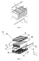
- a power battery module 100 comprises a battery pack 9, an upper case 6, a lower case 7.
- the battery pack 9 comprises a plurality of cells 91 connected in series or parallel.
- the lower case 7 is adapted to be mated with the upper case 6 to form a chamber in which the battery pack 9 is located so that the battery pack 9 is securely held in a Z-axis direction of the battery pack 9.
- At least a baffle plate 8 is longitudinally disposed at a lateral side of the battery pack 9 between the lower case 7 and the upper case 6 to fix the battery pack 9 in a Z-X plane.
- at least a boss is formed on at least one of a bottom inner surface of the lower case 7 and a top inner surface of the upper case 6 in a Y-axis direction of the battery pack 9 to fix the battery pack 9 in the Y-axis direction.
- FIG. 2 shows an exploded perspective view of a power battery module according to an embodiment of the present invention.
- a pair of baffle plates 8 are longitudinally disposed beside two outmost cells 91 respectively and are interposed between the lower case 7 and the upper case 6.
- a plurality of bosses 76 such as two, may be disposed on the bottom of the lower case 7 which are parallel to the bottom surface of the battery pack 9.
- the bosses 76 may be formed the top inner surface of the upper case 6 which are parallel to the top surface of the battery pack 9.
- the upper case 6 and the lower case 7 may be configured to securely position the battery pack 9 in the Z-axis direction.
- the baffle plates 8 are configured to securely position the battery pack 9 in the Y-axis direction
- the boss (76) as shown in Fig. 4 may be configured to securely position the battery pack 9 in the X-axis direction.
- the boss 76 is disposed on an inner bottom surface of the lower case 7 and parallel to a front surface of the battery pack 9 as shown in Fig. 2 , which achieves the position of the battery pack 9 in the X-axis direction.
- the bosses 76 may be preferably disposed on the inner bottom surface of the lower case 7 and the inner top surface of the upper case 6 which are parallel to the front surface of the battery pack 9 as shown in Fig. 2 .
- the material of the baffle plate 8 is plastic, which is an insulator with a suitable mechanical strength, heat distortion temperature, low-temperature embrittlement property and a chemical corrosion resistance etc.
- the baffle plate 8 is formed with a protruding portion 81 on the lateral side of the baffle plate 8, and a mating groove 75 is formed on the lateral side of the lower case 7 to fix the baffle plate 8.
- the mating groove 75 may be formed on the lateral side of the upper case.
- the baffle plate 8 is configured to be a plate with a trapezoid cross section with a thickness of approximately 1.5-10mm.
- a diaphragm may be interposed between the neighboring cells.
- the diaphragm is made of insulating plastic material with a mechanical strength, wear resistance, low-temperature embrittlement property and chemical corrosion resistance adapted to the requirement of the battery pack 9.
- At least one of the upper case 6 and the lower case 7 may further comprise a sealing member which may be disposed on the mating surfaces of the upper case 6 or/and the lower case 7.
- at least one of the upper case 6 and the lower case 7 may further comprise a sealing groove 74 formed on one of the upper case 6 or /and the lower case 7.
- the sealing member is disposed in the sealing groove 74.
- the material of the sealing member 10 may be rubber, with proper distortion and chemical corrosion resistance properties.
- a pair of electrode outlet 62 are disposed on both side of the lower case 7 which are configured for the connection of the anode and cathode of the cells 91. Further, a gas passing opening may be formed on the lower case 7 for battery temperature modulating.
- the upper case 6 may be connected with the lower case 7 in a snap-fit manner.
- the upper case 6 and the lower case 7 may comprise a plurality of connecting holes, disposed on four sides of the upper case 6 and the lower case 7.
- the connecting holes on the upper case 6 are corresponding to the connecting holes on the lower case 7.
- a connecting member, such as a stud bolt, may pass through a connecting hole to connect the upper case 6 with the lower case 7 accordingly.
- the battery pack 9 is securely positioned in the Z-axis direction.
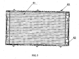
- the upper case 6 and the lower case 7 may be formed with strengthening ribs on external surfaces thereof.
- the strengthening ribs enhance the mechanical strength of the power battery module 100 to prevent the power battery module 100 from being damaged in a collision situation.
- the strengthening ribs may be disposed vertically and horizontally on the external surfaces of the upper case 6 and the lower case 7 respectively according to the suffered stress on the upper case 6 and the lower case 7.
- the thickness of the upper and lower cases 6, 7 may be about 3-5mm and the thickness of the strengthening ribs may be about 5-12mm.
- the material of the upper case 6 and the lower case 7 may be plastic with suitable mechanical strength, heat distortion temperature, low temperature embrittlement and chemical corrosion resistance properties.
- Figure 2 shows an exploded perspective view of a power battery module 100 according to an embodiment of the present invention.
- the upper case 6 may comprise a plurality of thread connecting holes 63, disposed at the sides of the upper case 6.
- the lower case 7 comprises a plurality of thread connecting holes 73, formed on the lower case 7.
- the thread connecting holes 63 on the upper case 6 are corresponding to the thread connecting holes 73 on the lower case 7.
- the upper case 6 is connected with the lower case 7 through bolts or screws. And then the battery pack 9 is securely positioned in the Z-axis direction, namely, the battery pack 9 is positioned in the width direction of the battery pack 9.
- the lower case 7 further comprises the sealing groove 74, formed on the mating surface of the lower case 7 to accommodate the sealing member 10.
- the upper case 6 also comprises a sealing groove formed on the mating surface of the upper case 6.
- the sealing member 10 is preferably disposed in the sealing groove 74 to get a better sealing effect, and then the short circuit caused by battery liquid leak due to collision is avoided.
- the material of the upper case 6 is polyphenylene oxide.
- the strengthening ribs 61 are formed on the upper case 6 through integral injection molding, to ensure the strength of the upper case 6.
- the material of the lower case 7 is the one consisting of polyphenylene oxide and 10% glass fiber.
- the strengthening ribs 72 are formed on the lower case 7 to ensure the strength of the lower case 7.
- FIG. 3 shows a cross sectional view of the power battery module 100 according to an embodiment of the present invention along Y-Z plane.
- the baffle plates 8 are disposed at the two outmost cell of the battery pack 9 respectively.
- the baffle plate 8 comprises the protruding portion 81.
- the low case comprises the mating groove 75.
- the baffle plate 8 is fitted in the lower case 7 and then the battery pack 9 is clamped by the baffle plates 8 accordingly.
- the battery pack 9 is positioned in the Y-axis direction, namely, the battery pack 9 is positioned in the thickness direction of the battery pack 9.
- the upper case 6 also comprises a mating groove 75.
- the baffle plate 8 is fitted in the lower case 7 and the upper case 6 respectively.
- the lower case 7 further comprises a pair of electrode outlet 62 disposed on the right side of the lower case 7 which are configured for the connection of the anode and cathode of the cell.
- the gas passing opening 71 for modulating the temperature of the battery pack 9 is formed on the right wall of the lower case 7.
- Figure 4 shows a cross sectional view of a power battery module 100 according to an embodiment of the present invention along X-Z plane.
- two bosses 76 are formed on the inner bottom surface of the lower case 7 and the bosses 76 are parallel to an edge (not shown in Fig. 4 ) of the battery pack 9.
- the battery pack 9 is fixed by the bosses when the battery pack 9 is positioned in the lower case 7. And then the battery pack 9 is securely positioned in the X-axis direction.
Landscapes
- Chemical & Material Sciences (AREA)
- Chemical Kinetics & Catalysis (AREA)
- Electrochemistry (AREA)
- General Chemical & Material Sciences (AREA)
- Inorganic Chemistry (AREA)
- Engineering & Computer Science (AREA)
- Composite Materials (AREA)
- Materials Engineering (AREA)
- Battery Mounting, Suspending (AREA)
Claims (5)
- Module de batterie d'alimentation (100), comprenant :un bloc-batterie (9) comprenant une pluralité de cellules reliées en série ou en parallèle ;un boîtier supérieur (6) ;un boîtier inférieur (7) adapté pour être conjugué avec le boîtier supérieur (6) pour former une chambre dans laquelle le bloc-batterie (9) est situé de sorte que le bloc-batterie (9) soit maintenu de manière stable dans une direction de hauteur du bloc-batterie (9) ;au moins une plaque de déviation (8) disposée longitudinalement au niveau d'un côté latéral du bloc-batterie (9) entre le boîtier inférieur (7) et le boîtier supérieur (6) pour fixer le bloc-batterie (9) dans une direction latérale,caractérisé en ce qu'une partie en saillie (81) est formée sur le côté latéral de la plaque de déviation (8), et une rainure conjuguée (75) est formée sur le côté latéral du boîtier supérieur (6) et/ou du boîtier inférieur (7) pour fixer la plaque de déviation (8) de sorte que le bloc-batterie (9) soit serré par la plaque de déviation (8) ; où le matériau de la plaque de déviation (8) est du plastique et où la plaque de déviation (8) est configurée de manière à être une plaque avec une section transversale trapézoïdale ; eten ce que le module de batterie d'alimentation (100) comprend au moins un bossage (76) formé sur au moins l'une d'une surface interne inférieure du boîtier inférieur (7) et d'une surface interne supérieure du boîtier supérieur (6) dans une direction de la longueur du bloc-batterie (9) pour fixer le bloc-batterie (9) dans la direction de la longueur.
- Module de batterie d'alimentation (100) selon la revendication 1, dans lequel la plaque de déviation (8) a une épaisseur se trouvant dans une plage allant d'environ 1,5 à 10 mm.
- Module de batterie d'alimentation (100) selon la revendication 1, comprenant en outre un élément d'étanchéité (10) prévu entre des surfaces conjuguées des boîtiers supérieur et inférieur.
- Module de batterie d'alimentation (100) selon la revendication 1, dans lequel le boîtier supérieur (6) et le boîtier inférieur (7) Sont formés avec des trous de connexion correspondants (73) de sorte que le boîtier supérieur (6) et le boîtier inférieur (7) soient fixés par un élément de connexion pénétrant à travers les trous de connexion (73).
- Module de batterie d'alimentation (100) selon la revendication 1, dans lequel une paire de plaques de déviation (8) sont disposées longitudinalement au niveau des deux côtés latéraux du bloc-batterie (9).
Applications Claiming Priority (2)
| Application Number | Priority Date | Filing Date | Title |
|---|---|---|---|
| CN200920131272XU CN201408805Y (zh) | 2009-04-30 | 2009-04-30 | 一种动力电池模块 |
| PCT/CN2010/071927 WO2010124566A1 (fr) | 2009-04-30 | 2010-04-20 | Module de batterie d'alimentation |
Publications (3)
| Publication Number | Publication Date |
|---|---|
| EP2425482A1 EP2425482A1 (fr) | 2012-03-07 |
| EP2425482A4 EP2425482A4 (fr) | 2013-04-10 |
| EP2425482B1 true EP2425482B1 (fr) | 2014-07-23 |
Family
ID=41679751
Family Applications (1)
| Application Number | Title | Priority Date | Filing Date |
|---|---|---|---|
| EP10769255.0A Active EP2425482B1 (fr) | 2009-04-30 | 2010-04-20 | Module de batterie d'alimentation |
Country Status (6)
| Country | Link |
|---|---|
| US (1) | US20120040229A1 (fr) |
| EP (1) | EP2425482B1 (fr) |
| JP (1) | JP5552156B2 (fr) |
| KR (1) | KR20120007069A (fr) |
| CN (1) | CN201408805Y (fr) |
| WO (1) | WO2010124566A1 (fr) |
Families Citing this family (9)
| Publication number | Priority date | Publication date | Assignee | Title |
|---|---|---|---|---|
| CN201408805Y (zh) * | 2009-04-30 | 2010-02-17 | 比亚迪股份有限公司 | 一种动力电池模块 |
| KR101201740B1 (ko) * | 2010-11-12 | 2012-11-15 | 에스비리모티브 주식회사 | 전지 모듈 |
| KR101898011B1 (ko) * | 2012-05-15 | 2018-09-12 | 에스케이이노베이션 주식회사 | 밀폐형 배터리 모듈 |
| KR101425569B1 (ko) * | 2013-02-25 | 2014-08-01 | 주식회사 피엠그로우 | 배터리 케이스 |
| KR101883386B1 (ko) * | 2015-03-16 | 2018-07-30 | 주식회사 엘지화학 | 전지 압축 저지체와 이를 포함하는 전지 모듈 |
| KR102119152B1 (ko) * | 2017-12-12 | 2020-06-04 | 삼성에스디아이 주식회사 | 배터리 팩 |
| CN108520931A (zh) * | 2018-06-11 | 2018-09-11 | 浙江乾坤新能源科技有限公司 | 电池包盒 |
| CN111048705A (zh) * | 2018-10-12 | 2020-04-21 | 奥动新能源汽车科技有限公司 | 车载动力电池及其制造方法、新能源车 |
| CN116261526A (zh) * | 2022-06-13 | 2023-06-13 | 宁德时代新能源科技股份有限公司 | 电池包及用电装置 |
Family Cites Families (20)
| Publication number | Priority date | Publication date | Assignee | Title |
|---|---|---|---|---|
| JPS601767A (ja) * | 1983-06-20 | 1985-01-07 | Shin Kobe Electric Mach Co Ltd | 密閉形鉛蓄電池 |
| US5558949A (en) * | 1993-12-27 | 1996-09-24 | Honda Giken Kogyo Kabushiki Kaisha | Battery box |
| DE19504687C1 (de) * | 1995-02-13 | 1996-03-14 | Deutsche Automobilgesellsch | Batteriekasten für mehrere darin angeordnete elektrochemische Speicher |
| EP0952620B1 (fr) * | 1998-03-25 | 2002-11-20 | Matsushita Electric Industrial Co., Ltd. | Accumulateur étanche et système modulaire approprié |
| JP4631118B2 (ja) * | 1999-02-15 | 2011-02-16 | ソニー株式会社 | 移動体搭載用バッテリ装置 |
| DE19930399A1 (de) * | 1999-07-01 | 2001-01-11 | Daimler Chrysler Ag | Batteriekasten und Kraftfahrzeug |
| CN2450785Y (zh) * | 2000-11-17 | 2001-09-26 | 天津和平海湾电源集团有限公司 | 方型密封电池紧固组装结构 |
| JP3591528B2 (ja) * | 2002-07-23 | 2004-11-24 | 日産自動車株式会社 | モジュール電池 |
| CN2679860Y (zh) * | 2003-12-29 | 2005-02-16 | 比亚迪股份有限公司 | 方形锂离子动力电池组 |
| US20050170238A1 (en) * | 2004-02-04 | 2005-08-04 | Abu-Isa Ismat A. | Fire shielding battery case |
| JP4556594B2 (ja) * | 2004-09-28 | 2010-10-06 | 新神戸電機株式会社 | 組電池、組電池群及び電池モジュール |
| US20060091849A1 (en) * | 2004-11-01 | 2006-05-04 | Huynh Due Q | Modular battery pack |
| US20070087266A1 (en) * | 2005-10-18 | 2007-04-19 | Debbi Bourke | Modular battery system |
| JP4783137B2 (ja) * | 2005-12-15 | 2011-09-28 | 日立ビークルエナジー株式会社 | 電池モジュール |
| TWM320249U (en) * | 2007-03-29 | 2007-10-01 | High Tech Battery Inc | Portable power supply |
| JP5151363B2 (ja) * | 2007-09-28 | 2013-02-27 | 三菱自動車工業株式会社 | 電気自動車用バッテリケース |
| CN201134448Y (zh) * | 2007-10-31 | 2008-10-15 | 天津力神电池股份有限公司 | 大容量锂离子动力电池壳体 |
| CN201146200Y (zh) * | 2007-12-18 | 2008-11-05 | 比亚迪股份有限公司 | 一种电池组用壳体及包括该壳体的电池组 |
| CN201160087Y (zh) * | 2008-03-03 | 2008-12-03 | 安耐信(北京)储能技术有限公司 | 车用动力电池模块 |
| CN201408805Y (zh) * | 2009-04-30 | 2010-02-17 | 比亚迪股份有限公司 | 一种动力电池模块 |
-
2009
- 2009-04-30 CN CN200920131272XU patent/CN201408805Y/zh not_active Expired - Lifetime
-
2010
- 2010-04-20 KR KR1020117028588A patent/KR20120007069A/ko not_active Ceased
- 2010-04-20 EP EP10769255.0A patent/EP2425482B1/fr active Active
- 2010-04-20 WO PCT/CN2010/071927 patent/WO2010124566A1/fr not_active Ceased
- 2010-04-20 JP JP2012507588A patent/JP5552156B2/ja active Active
-
2011
- 2011-10-28 US US13/284,120 patent/US20120040229A1/en not_active Abandoned
Also Published As
| Publication number | Publication date |
|---|---|
| KR20120007069A (ko) | 2012-01-19 |
| JP2012525666A (ja) | 2012-10-22 |
| EP2425482A1 (fr) | 2012-03-07 |
| WO2010124566A1 (fr) | 2010-11-04 |
| CN201408805Y (zh) | 2010-02-17 |
| JP5552156B2 (ja) | 2014-07-16 |
| EP2425482A4 (fr) | 2013-04-10 |
| US20120040229A1 (en) | 2012-02-16 |
Similar Documents
| Publication | Publication Date | Title |
|---|---|---|
| EP2425482B1 (fr) | Module de batterie d'alimentation | |
| KR101403930B1 (ko) | 콤팩트한 구조의 전지팩 | |
| JP5949796B2 (ja) | 接続ユニット | |
| EP3151307B1 (fr) | Module de batterie et bloc-batterie le comprenant | |
| JP5222351B2 (ja) | バッテリ・パック | |
| KR101314454B1 (ko) | 전지 팩 | |
| US20120263995A1 (en) | Battery module and battery pack | |
| WO2013018283A1 (fr) | Ensemble de batteries | |
| US20160301051A1 (en) | Assembled battery | |
| KR102760922B1 (ko) | 배터리, 전기기기 및 배터리의 제조 방법 | |
| US9356326B2 (en) | Top cover and battery pack having the same | |
| JP2012123980A (ja) | 電池モジュール及びプレート組立体 | |
| CN116114108B (zh) | 电池、用电设备、制备电池的方法和设备 | |
| CN116325311B (zh) | 电池模块、电池、用电设备、制备电池的方法和设备 | |
| KR102466707B1 (ko) | 버스바 매설형 커버구조를 갖는 배터리모듈 및 배터리팩 | |
| WO2023176753A1 (fr) | Dispositif de stockage d'énergie | |
| US20230138950A1 (en) | Energy storage apparatus | |
| US20250118843A1 (en) | Battery pack | |
| US20230129680A1 (en) | Energy storage apparatus | |
| CN211629189U (zh) | 用于电池包固定电芯的端板以及电池包 | |
| JP2024021469A (ja) | 蓄電装置 | |
| CN221805779U (zh) | 电池单体、电池和用电装置 | |
| JP7826759B2 (ja) | 蓄電装置 | |
| US20250158197A1 (en) | Battery pack and battery assembly | |
| JP2021132014A (ja) | 蓄電装置 |
Legal Events
| Date | Code | Title | Description |
|---|---|---|---|
| PUAI | Public reference made under article 153(3) epc to a published international application that has entered the european phase |
Free format text: ORIGINAL CODE: 0009012 |
|
| 17P | Request for examination filed |
Effective date: 20111005 |
|
| AK | Designated contracting states |
Kind code of ref document: A1 Designated state(s): AT BE BG CH CY CZ DE DK EE ES FI FR GB GR HR HU IE IS IT LI LT LU LV MC MK MT NL NO PL PT RO SE SI SK SM TR |
|
| DAX | Request for extension of the european patent (deleted) | ||
| A4 | Supplementary search report drawn up and despatched |
Effective date: 20130308 |
|
| RIC1 | Information provided on ipc code assigned before grant |
Ipc: H01M 2/10 20060101AFI20130304BHEP |
|
| 17Q | First examination report despatched |
Effective date: 20130403 |
|
| REG | Reference to a national code |
Ref country code: DE Ref legal event code: R079 Ref document number: 602010017755 Country of ref document: DE Free format text: PREVIOUS MAIN CLASS: H01M0010000000 Ipc: H01M0002100000 |
|
| GRAP | Despatch of communication of intention to grant a patent |
Free format text: ORIGINAL CODE: EPIDOSNIGR1 |
|
| RIC1 | Information provided on ipc code assigned before grant |
Ipc: H01M 2/10 20060101AFI20130902BHEP |
|
| INTG | Intention to grant announced |
Effective date: 20130926 |
|
| GRAP | Despatch of communication of intention to grant a patent |
Free format text: ORIGINAL CODE: EPIDOSNIGR1 |
|
| INTG | Intention to grant announced |
Effective date: 20140217 |
|
| GRAS | Grant fee paid |
Free format text: ORIGINAL CODE: EPIDOSNIGR3 |
|
| GRAA | (expected) grant |
Free format text: ORIGINAL CODE: 0009210 |
|
| AK | Designated contracting states |
Kind code of ref document: B1 Designated state(s): AT BE BG CH CY CZ DE DK EE ES FI FR GB GR HR HU IE IS IT LI LT LU LV MC MK MT NL NO PL PT RO SE SI SK SM TR |
|
| REG | Reference to a national code |
Ref country code: GB Ref legal event code: FG4D |
|
| REG | Reference to a national code |
Ref country code: CH Ref legal event code: EP |
|
| REG | Reference to a national code |
Ref country code: IE Ref legal event code: FG4D |
|
| REG | Reference to a national code |
Ref country code: AT Ref legal event code: REF Ref document number: 679308 Country of ref document: AT Kind code of ref document: T Effective date: 20140815 |
|
| REG | Reference to a national code |
Ref country code: DE Ref legal event code: R096 Ref document number: 602010017755 Country of ref document: DE Effective date: 20140904 |
|
| REG | Reference to a national code |
Ref country code: AT Ref legal event code: MK05 Ref document number: 679308 Country of ref document: AT Kind code of ref document: T Effective date: 20140723 |
|
| REG | Reference to a national code |
Ref country code: NL Ref legal event code: VDEP Effective date: 20140723 |
|
| REG | Reference to a national code |
Ref country code: LT Ref legal event code: MG4D |
|
| PG25 | Lapsed in a contracting state [announced via postgrant information from national office to epo] |
Ref country code: BG Free format text: LAPSE BECAUSE OF FAILURE TO SUBMIT A TRANSLATION OF THE DESCRIPTION OR TO PAY THE FEE WITHIN THE PRESCRIBED TIME-LIMIT Effective date: 20141023 Ref country code: ES Free format text: LAPSE BECAUSE OF FAILURE TO SUBMIT A TRANSLATION OF THE DESCRIPTION OR TO PAY THE FEE WITHIN THE PRESCRIBED TIME-LIMIT Effective date: 20140723 Ref country code: NO Free format text: LAPSE BECAUSE OF FAILURE TO SUBMIT A TRANSLATION OF THE DESCRIPTION OR TO PAY THE FEE WITHIN THE PRESCRIBED TIME-LIMIT Effective date: 20141023 Ref country code: PT Free format text: LAPSE BECAUSE OF FAILURE TO SUBMIT A TRANSLATION OF THE DESCRIPTION OR TO PAY THE FEE WITHIN THE PRESCRIBED TIME-LIMIT Effective date: 20141124 Ref country code: GR Free format text: LAPSE BECAUSE OF FAILURE TO SUBMIT A TRANSLATION OF THE DESCRIPTION OR TO PAY THE FEE WITHIN THE PRESCRIBED TIME-LIMIT Effective date: 20141024 Ref country code: SE Free format text: LAPSE BECAUSE OF FAILURE TO SUBMIT A TRANSLATION OF THE DESCRIPTION OR TO PAY THE FEE WITHIN THE PRESCRIBED TIME-LIMIT Effective date: 20140723 Ref country code: FI Free format text: LAPSE BECAUSE OF FAILURE TO SUBMIT A TRANSLATION OF THE DESCRIPTION OR TO PAY THE FEE WITHIN THE PRESCRIBED TIME-LIMIT Effective date: 20140723 Ref country code: LT Free format text: LAPSE BECAUSE OF FAILURE TO SUBMIT A TRANSLATION OF THE DESCRIPTION OR TO PAY THE FEE WITHIN THE PRESCRIBED TIME-LIMIT Effective date: 20140723 |
|
| PG25 | Lapsed in a contracting state [announced via postgrant information from national office to epo] |
Ref country code: IS Free format text: LAPSE BECAUSE OF FAILURE TO SUBMIT A TRANSLATION OF THE DESCRIPTION OR TO PAY THE FEE WITHIN THE PRESCRIBED TIME-LIMIT Effective date: 20141123 Ref country code: AT Free format text: LAPSE BECAUSE OF FAILURE TO SUBMIT A TRANSLATION OF THE DESCRIPTION OR TO PAY THE FEE WITHIN THE PRESCRIBED TIME-LIMIT Effective date: 20140723 Ref country code: NL Free format text: LAPSE BECAUSE OF FAILURE TO SUBMIT A TRANSLATION OF THE DESCRIPTION OR TO PAY THE FEE WITHIN THE PRESCRIBED TIME-LIMIT Effective date: 20140723 Ref country code: LV Free format text: LAPSE BECAUSE OF FAILURE TO SUBMIT A TRANSLATION OF THE DESCRIPTION OR TO PAY THE FEE WITHIN THE PRESCRIBED TIME-LIMIT Effective date: 20140723 Ref country code: CY Free format text: LAPSE BECAUSE OF FAILURE TO SUBMIT A TRANSLATION OF THE DESCRIPTION OR TO PAY THE FEE WITHIN THE PRESCRIBED TIME-LIMIT Effective date: 20140723 Ref country code: PL Free format text: LAPSE BECAUSE OF FAILURE TO SUBMIT A TRANSLATION OF THE DESCRIPTION OR TO PAY THE FEE WITHIN THE PRESCRIBED TIME-LIMIT Effective date: 20140723 Ref country code: HR Free format text: LAPSE BECAUSE OF FAILURE TO SUBMIT A TRANSLATION OF THE DESCRIPTION OR TO PAY THE FEE WITHIN THE PRESCRIBED TIME-LIMIT Effective date: 20140723 |
|
| REG | Reference to a national code |
Ref country code: DE Ref legal event code: R097 Ref document number: 602010017755 Country of ref document: DE |
|
| PG25 | Lapsed in a contracting state [announced via postgrant information from national office to epo] |
Ref country code: RO Free format text: LAPSE BECAUSE OF FAILURE TO SUBMIT A TRANSLATION OF THE DESCRIPTION OR TO PAY THE FEE WITHIN THE PRESCRIBED TIME-LIMIT Effective date: 20140723 Ref country code: SK Free format text: LAPSE BECAUSE OF FAILURE TO SUBMIT A TRANSLATION OF THE DESCRIPTION OR TO PAY THE FEE WITHIN THE PRESCRIBED TIME-LIMIT Effective date: 20140723 Ref country code: IT Free format text: LAPSE BECAUSE OF FAILURE TO SUBMIT A TRANSLATION OF THE DESCRIPTION OR TO PAY THE FEE WITHIN THE PRESCRIBED TIME-LIMIT Effective date: 20140723 Ref country code: DK Free format text: LAPSE BECAUSE OF FAILURE TO SUBMIT A TRANSLATION OF THE DESCRIPTION OR TO PAY THE FEE WITHIN THE PRESCRIBED TIME-LIMIT Effective date: 20140723 Ref country code: EE Free format text: LAPSE BECAUSE OF FAILURE TO SUBMIT A TRANSLATION OF THE DESCRIPTION OR TO PAY THE FEE WITHIN THE PRESCRIBED TIME-LIMIT Effective date: 20140723 Ref country code: CZ Free format text: LAPSE BECAUSE OF FAILURE TO SUBMIT A TRANSLATION OF THE DESCRIPTION OR TO PAY THE FEE WITHIN THE PRESCRIBED TIME-LIMIT Effective date: 20140723 |
|
| PLBE | No opposition filed within time limit |
Free format text: ORIGINAL CODE: 0009261 |
|
| STAA | Information on the status of an ep patent application or granted ep patent |
Free format text: STATUS: NO OPPOSITION FILED WITHIN TIME LIMIT |
|
| 26N | No opposition filed |
Effective date: 20150424 |
|
| PG25 | Lapsed in a contracting state [announced via postgrant information from national office to epo] |
Ref country code: MC Free format text: LAPSE BECAUSE OF FAILURE TO SUBMIT A TRANSLATION OF THE DESCRIPTION OR TO PAY THE FEE WITHIN THE PRESCRIBED TIME-LIMIT Effective date: 20140723 Ref country code: SI Free format text: LAPSE BECAUSE OF FAILURE TO SUBMIT A TRANSLATION OF THE DESCRIPTION OR TO PAY THE FEE WITHIN THE PRESCRIBED TIME-LIMIT Effective date: 20140723 Ref country code: LU Free format text: LAPSE BECAUSE OF FAILURE TO SUBMIT A TRANSLATION OF THE DESCRIPTION OR TO PAY THE FEE WITHIN THE PRESCRIBED TIME-LIMIT Effective date: 20150420 |
|
| REG | Reference to a national code |
Ref country code: CH Ref legal event code: PL |
|
| REG | Reference to a national code |
Ref country code: IE Ref legal event code: MM4A |
|
| PG25 | Lapsed in a contracting state [announced via postgrant information from national office to epo] |
Ref country code: CH Free format text: LAPSE BECAUSE OF NON-PAYMENT OF DUE FEES Effective date: 20150430 Ref country code: LI Free format text: LAPSE BECAUSE OF NON-PAYMENT OF DUE FEES Effective date: 20150430 |
|
| REG | Reference to a national code |
Ref country code: FR Ref legal event code: PLFP Year of fee payment: 7 |
|
| PG25 | Lapsed in a contracting state [announced via postgrant information from national office to epo] |
Ref country code: IE Free format text: LAPSE BECAUSE OF NON-PAYMENT OF DUE FEES Effective date: 20150420 |
|
| PG25 | Lapsed in a contracting state [announced via postgrant information from national office to epo] |
Ref country code: BE Free format text: LAPSE BECAUSE OF FAILURE TO SUBMIT A TRANSLATION OF THE DESCRIPTION OR TO PAY THE FEE WITHIN THE PRESCRIBED TIME-LIMIT Effective date: 20140723 |
|
| PG25 | Lapsed in a contracting state [announced via postgrant information from national office to epo] |
Ref country code: MT Free format text: LAPSE BECAUSE OF FAILURE TO SUBMIT A TRANSLATION OF THE DESCRIPTION OR TO PAY THE FEE WITHIN THE PRESCRIBED TIME-LIMIT Effective date: 20140723 |
|
| REG | Reference to a national code |
Ref country code: FR Ref legal event code: PLFP Year of fee payment: 8 |
|
| PG25 | Lapsed in a contracting state [announced via postgrant information from national office to epo] |
Ref country code: HU Free format text: LAPSE BECAUSE OF FAILURE TO SUBMIT A TRANSLATION OF THE DESCRIPTION OR TO PAY THE FEE WITHIN THE PRESCRIBED TIME-LIMIT; INVALID AB INITIO Effective date: 20100420 Ref country code: SM Free format text: LAPSE BECAUSE OF FAILURE TO SUBMIT A TRANSLATION OF THE DESCRIPTION OR TO PAY THE FEE WITHIN THE PRESCRIBED TIME-LIMIT Effective date: 20140723 |
|
| PG25 | Lapsed in a contracting state [announced via postgrant information from national office to epo] |
Ref country code: TR Free format text: LAPSE BECAUSE OF FAILURE TO SUBMIT A TRANSLATION OF THE DESCRIPTION OR TO PAY THE FEE WITHIN THE PRESCRIBED TIME-LIMIT Effective date: 20140723 |
|
| REG | Reference to a national code |
Ref country code: FR Ref legal event code: PLFP Year of fee payment: 9 |
|
| PG25 | Lapsed in a contracting state [announced via postgrant information from national office to epo] |
Ref country code: MK Free format text: LAPSE BECAUSE OF FAILURE TO SUBMIT A TRANSLATION OF THE DESCRIPTION OR TO PAY THE FEE WITHIN THE PRESCRIBED TIME-LIMIT Effective date: 20140723 |
|
| REG | Reference to a national code |
Ref country code: DE Ref legal event code: R079 Ref document number: 602010017755 Country of ref document: DE Free format text: PREVIOUS MAIN CLASS: H01M0002100000 Ipc: H01M0050200000 |
|
| REG | Reference to a national code |
Ref country code: DE Ref legal event code: R082 Ref document number: 602010017755 Country of ref document: DE Representative=s name: DEHNSGERMANY PARTNERSCHAFT VON PATENTANWAELTEN, DE Ref country code: DE Ref legal event code: R082 Ref document number: 602010017755 Country of ref document: DE Ref country code: DE Ref legal event code: R082 Ref document number: 602010017755 Country of ref document: DE Representative=s name: DEHNS GERMANY PARTNERSCHAFT MBB, DE |
|
| P01 | Opt-out of the competence of the unified patent court (upc) registered |
Effective date: 20230527 |
|
| REG | Reference to a national code |
Ref country code: DE Ref legal event code: R082 Ref document number: 602010017755 Country of ref document: DE Representative=s name: DEHNSGERMANY PARTNERSCHAFT VON PATENTANWAELTEN, DE Ref country code: DE Ref legal event code: R082 Ref document number: 602010017755 Country of ref document: DE Representative=s name: DEHNS GERMANY PARTNERSCHAFT MBB, DE |
|
| PGFP | Annual fee paid to national office [announced via postgrant information from national office to epo] |
Ref country code: DE Payment date: 20250422 Year of fee payment: 16 |
|
| PGFP | Annual fee paid to national office [announced via postgrant information from national office to epo] |
Ref country code: FR Payment date: 20250425 Year of fee payment: 16 |
|
| PGFP | Annual fee paid to national office [announced via postgrant information from national office to epo] |
Ref country code: GB Payment date: 20260324 Year of fee payment: 17 |