EP2425400B1 - Method of selecting an optimal viewing angle position for a camera - Google Patents
Method of selecting an optimal viewing angle position for a camera Download PDFInfo
- Publication number
- EP2425400B1 EP2425400B1 EP10717273A EP10717273A EP2425400B1 EP 2425400 B1 EP2425400 B1 EP 2425400B1 EP 10717273 A EP10717273 A EP 10717273A EP 10717273 A EP10717273 A EP 10717273A EP 2425400 B1 EP2425400 B1 EP 2425400B1
- Authority
- EP
- European Patent Office
- Prior art keywords
- camera
- viewing angle
- quantitative score
- interest
- regions
- Prior art date
- Legal status (The legal status is an assumption and is not a legal conclusion. Google has not performed a legal analysis and makes no representation as to the accuracy of the status listed.)
- Active
Links
Images

Classifications
-
- G—PHYSICS
- G06—COMPUTING OR CALCULATING; COUNTING
- G06T—IMAGE DATA PROCESSING OR GENERATION, IN GENERAL
- G06T7/00—Image analysis
- G06T7/70—Determining position or orientation of objects or cameras
- G06T7/73—Determining position or orientation of objects or cameras using feature-based methods
- G06T7/74—Determining position or orientation of objects or cameras using feature-based methods involving reference images or patches
-
- G—PHYSICS
- G06—COMPUTING OR CALCULATING; COUNTING
- G06T—IMAGE DATA PROCESSING OR GENERATION, IN GENERAL
- G06T2207/00—Indexing scheme for image analysis or image enhancement
- G06T2207/10—Image acquisition modality
- G06T2207/10016—Video; Image sequence
-
- G—PHYSICS
- G06—COMPUTING OR CALCULATING; COUNTING
- G06T—IMAGE DATA PROCESSING OR GENERATION, IN GENERAL
- G06T2207/00—Indexing scheme for image analysis or image enhancement
- G06T2207/30—Subject of image; Context of image processing
- G06T2207/30244—Camera pose
Definitions
- the present invention relates to a method and a system for selecting an optimal viewing angle position for a camera.
- Computer vision or visual scene analysis is the scientific field of extracting information from images such as video sequences.
- the discipline is applied to a large number of applications, for instance for human visual activity recognition, the identification of human activities based on video data captured through one or more cameras.
- a critical issue in this and many other computer vision applications is the placement of the cameras.
- the camera setup determines whether the captured video material is suitable for the computer vision task or not.
- it is important that the camera is positioned in the best possible manner for that particular application meaning that when e.g. the application is video conferencing, it is important that all speakers are visible to the other parties, but the camera position tends to be fixed in such conferencing systems.
- Another video conferencing system sets its camera configuration based on the detected positions of the users ( JP 2005311734 ). These approaches are however only successful when the objects of interest do not occlude each other. They are however inadequate for many computer vision applications.
- the object of the present invention is to provide an improved solution to find the best possible setup for with as few cameras as possible.
- the present invention relates to a method of selecting an optimal viewing angle of an analog or digital camera in a computer vision system by use of an angle adjusting mechanism for the camera for adjusting the viewing angle of the camera, the method comprising:
- a large overlap indicates clearly an unfavorable viewing angle position, and the larger the distance is for the non overlapping regions of interest the more favorable will the viewing angle position be.
- the more the overlap is the higher will the quantitative score be.
- the more the distance is between the region of interest is the higher will the quantitative score be.
- the method further comprises defining a threshold quantitative score, where in case none of the determined quantitative scores is above the threshold quantitative score a command is issued indicating that the camera is position unfavorable and shall be re-positioned. In that way, the end-user is informed about that no optimal viewing angle position can be established.
- the present invention relates to a computer program product for instructing a processing unit to execute the above mentioned method steps when the product is run on a computer.
- the present invention relates to a computer vision system for automatically selecting an optimal viewing angle of an analog or digital camera, comprising:
- Figure 1 shows flowchart of an embodiment of a method according to the present invention of selecting an optimal viewing angle position for a camera but the camera can as an example a security camera, a web camera, any kind of analog or digital camera.
- a first quantitative score is determined for a first viewing angle position of the camera, where pre-selected regions of interest are used as reference areas.
- This step of determining is performed in accordance to a pre-defined quantitative score rule.
- this quantitative score rule is based on determining whether there is an overlap amongst the regions of interest for the first and the at least one second viewing angle positions.
- one region of interest could be a door frame and a second region of interest could be a table.
- An optimal angle position is where the door frame and the table do not overlap. Therefore, if these two regions of interest overlap the quantitative score will be lower than if these two areas do not overlap. This will be discussed in more details in conjunction with Fig. 2 .
- step (S2) 103 the angle position is adjusted from the first viewing angle position towards at least one second viewing angle position, where for each new angle position said quantitative is determined (S3) 105 in accordance to said pre-defined quantitative score rule.
- the camera may be mounted to or be an integral part of an angle adjusting mechanism that allows one or more degrees of freedom for the angle position adjustment.
- the angle adjusting mechanism allows the camera adjust the horizontal and the vertical angle and even the rotation angle of the camera.
- Such adjustment may be done manually by an end-user, or automatically by the camera itself which may be pre-programmed to changes the angle position two or more times, where for each angle position said quantitative score is determined.
- a target viewing angle position is determined based on the determined quantitative scores.
- the step of determining the target viewing angle position includes selecting the viewing angle position that is associated to the highest quantitative score as the target viewing angle position. Let's say the for a first angle position the score is -10, the second angle position the score is -1, and the third angle position the score is +5, the third angle position has the highest score and is selected as the target viewing angle position.
- a threshold quantitative score is defined such that in case none of the determined quantitative scores is above the threshold quantitative score a command is issued indicating that the camera is position unfavorable and shall be re-positioned.
- the threshold quantitative score could be the score zero, which indicates that there is no overlap between the region of interest (and no distance between the region of interest).
- the command that is issued could be in the form of a light signal by e.g. blinking red light or the command could be a voice command. If the camera is operated via a PC computer the computer screen could indicate to the end-user that the camera needs to be re-positioned.
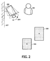
- Figure 2 depicts graphically an example where a camera 200 has been mounted to a wall 207 by an end-user 201.
- interest regions are defined or detected.
- interest regions may include the fridge, stove, sink, and so on.
- the end-user 201 has selected two regions of interest, area A 205 and area B 206, but the regions of interest have to be indicated at the beginning.
- the aim is to find the most optimal camera setup such that the regions of interest 205, 206 are far away from each other and without (or with less) overlap.
- the target setup (viewing angle + position) is associated to the largest score, which can indeed be negative, for example, if there is always an overlap between the regions of interest 205, 206. In such scenarios, the setup with the minimal overlap (corresponding to the largest negative score) will be selected.
- the camera After the end-user has placed the camera 200 at this initial position, the camera checks all viewing angles (tilt/pan rotation) to find the optimal viewing angle based on said quantitative score by iteratively and incrementally adjusting the camera's viewing angle, and recording said determined score for each angle.
- the camera decides which of the viewing angles are good enough which can e.g. be if there is no overlap between the two regions of interest 205, 206 or if the overlap is below threshold (e.g. only a small overlap). If such an optimal viewing angle is detected a stop process is initiated where e.g. the camera blinks a green light. If however none of the viewing angles are good enough, e.g.
- the camera or the computer vision system gives the end-user 201 guidance to re-position the camera (e.g., which direction to move). This is then continued until an optimal viewing angle (the target viewing angle) has been determined.
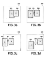
- Figure 3a-d depicts graphically four different viewing angle positions for the camera 200 shown in Fig. 2 for said two regions of interest, region A 205 and region B 206.
- the score may be given as a negative score (or low positive value), and its value is a function of the ratio of the overlapped region and the smaller occluded interest region.
- Interest regions that fall outside of the camera view 300 are also treated as overlapped, as shown in Figure 1c .
- the score is positive and its value is a function of the minimum distance d 301 between interest regions such that the larger the distance d is the larger becomes the score.
- the score of Fig. 3d is larger than that of Fig. 3b , indicating the setup of Fig. 3d is preferable to the setup of Fig. 3b . Accordingly, the viewing angle position that is associated to Fig. 3d has the highest quantitative score as becomes the target viewing angle position.
- the camera or the computer system coupled to the camera may indicate possible camera positions which may yield a better view. Assuming a situation as shown in Fig. 3a has the highest score, the overlapping of the interest regions is most likely to be resolved by moving the camera position horizontally and to the left (see from the point of view of the camera). As a result of the above, finding a suitable camera setup will be relatively easy even for a novice user.
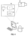
- Figure 4 shows an embodiment of a system 400 according to the present invention for automatically selecting an optimal viewing angle position for a camera 200, comprising a processor (P) 401, an angle adjusting mechanism (A_D_M) 402 for adjusting the angle position of the camera and a memory 404.
- P processor
- A_D_M angle adjusting mechanism
- the processor (P) 401 may either be integrated into the camera 200 or be comprised in a computer 403 that is operated by the end-user 201 and determines said quantitative scores as discussed previously in Figs. 1 and 2 , or two processors may be provided, one in the computer and one in the camera.
- the angle adjusting mechanism (A_D_M) 402 can be any means that adjusts the angle position of the camera iteratively and incrementally by adjusting the camera's viewing angle via tilt and/or pan and/or rotation.
- the determined scores are recorded and stored in the memory 404.
- the largest score at each time point is stored such that when a larger score is recorded it replaces the previous largest score in the memory and the corresponding viewing angle position.
- the memory may either be comprised in the computer 403 or in the camera 200.
- the adjustments of the viewing angles may be performed manually by the end-user 201, or the camera may be pre-programmed to perform a viewing angle "scan" where e.g. 10 different viewing angles are scanned where for each viewing angle the quantitative score is determined by the processor (P) 401 and stored in the memory 404.
- Each score is associated to the angle position for which the score was determined. As discussed previously in Figs. 1 and 2 , said target viewing angle position is subsequently determined.
- An appropriate software product may be provided that allows the end-user 201 to operate the camera via the end-user home computer, e.g. the end-user 201 can manually operate the camera 201 by e.g. entering how many viewing angles shall be scanned by the camera 200 or by entering which viewing angles should be scanned.
- the monitor of the computer 403 could e.g. display the different views seen by the camera 200 and display the viewing angles. In that way, the end-user 201 can estimate which viewing angles are likely to be the most optimal viewing angles. Subsequently, the end-user may enter several viewing angles and let the processor determine the scores for each viewing angle.
Landscapes
- Engineering & Computer Science (AREA)
- Computer Vision & Pattern Recognition (AREA)
- Physics & Mathematics (AREA)
- General Physics & Mathematics (AREA)
- Theoretical Computer Science (AREA)
- Studio Devices (AREA)
Description
- The present invention relates to a method and a system for selecting an optimal viewing angle position for a camera.
- Computer vision or visual scene analysis is the scientific field of extracting information from images such as video sequences. The discipline is applied to a large number of applications, for instance for human visual activity recognition, the identification of human activities based on video data captured through one or more cameras.
- A critical issue in this and many other computer vision applications is the placement of the cameras. As video sequences are projections of 3D space onto a 2D image plane by a camera, the camera setup (the position and the viewing angle) determines whether the captured video material is suitable for the computer vision task or not. For an application to function optimally, it is important that the camera is positioned in the best possible manner for that particular application, meaning that when e.g. the application is video conferencing, it is important that all speakers are visible to the other parties, but the camera position tends to be fixed in such conferencing systems. Several solutions for computer vision applications for such video conferencing exist. In
US 20070058879 as an example, the solution is based on panoramic, whereas inJP 2008061260 JP 2005311734 - Nearly all computer vision systems face a fundamental challenge, namely how to determine an optimal camera setup. This problem becomes especially relevant when the end-users themselves have to position the camera, instead of an expert. From the point of view of the end-users, it should preferably be easy and straightforward to find the optimal camera setup such that the objects of interest do not occlude each other. One possible solution is to use additional cameras. However, there are considerable downsides of this approach, such as the additional costs relating to installing additional cameras, and the additional effort required to install them.
- Furthermore, the following scientific papers are known that relate to the field of 3D computer graphics: Bares W. et al.: "Virtual 3D Camera Composition from Frame Constraints", ACM MULTIMEDIA 2000, 1 January 2000, which refers to a graphical interface that enables 3D visual artists or developers of interactive 3D virtual environments to efficiently define sophisticated camera compositions by creating storyboard frames, indicating how a desired shot should appear. Marchand E. et al.: "Image-based virtual camera motion strategies", PROCEEDINGS GRAPHICS INTERFACE, 1 May, 2000, pp. 69-76, which discloses a solution to the camera control problem in a virtual environment with the objective to present a general framework which allows the automatic control of a camera in a dynamic environment.
- The object of the present invention is to provide an improved solution to find the best possible setup for with as few cameras as possible.
- According to a first aspect, the present invention relates to a method of selecting an optimal viewing angle of an analog or digital camera in a computer vision system by use of an angle adjusting mechanism for the camera for adjusting the viewing angle of the camera, the method comprising:
- determining a first quantitative score for a first viewing angle of the camera using pre-selected regions of interest as reference areas, the determining being performed in accordance to a pre-defined quantitative score rule, where the pre-defined quantitative score rule includes determining whether there is an overlap amongst the regions of interest for the first and the at least one second viewing angles of the camera such that the more the overlap is between the regions of interest the lower will the quantitative score be, and the larger the distance is between the regions of interest the larger will the quantitative score be,
- adjusting the viewing angle of the camera from the first viewing angle towards at least one second viewing angle of the camera,
- determining for each at least one second viewing angle of the camera a second quantitative score in accordance to said pre-defined quantitative score rule, and
- determining a target viewing angle of the camera as the optimal viewing angle based on the determined quantitative scores by selecting the viewing angle of the camera that is associated to the highest quantitative score as the target viewing angle of the camera.
- Thus, guidance for an end-user is provided which allows the end-user in a user friendly and automatic way to setup camera for computer vision systems. Also, an economical solution is provided since in case the computer vision system is e.g. a surveillance system fewer cameras may be need since each respective camera is capable of optimizing the viewing angle position.
- Accordingly, a large overlap indicates clearly an unfavorable viewing angle position, and the larger the distance is for the non overlapping regions of interest the more favorable will the viewing angle position be. Thus, in scenarios where e.g. for all the viewing angle positions there is an overlap, the less the overlap is the higher will the quantitative score be. Also, in scenarios where there are several regions of interest where there is no overlap, the more the distance is between the region of interest is the higher will the quantitative score be.
- In one embodiment, the method further comprises defining a threshold quantitative score, where in case none of the determined quantitative scores is above the threshold quantitative score a command is issued indicating that the camera is position unfavorable and shall be re-positioned. In that way, the end-user is informed about that no optimal viewing angle position can be established.
- According to a second aspect, the present invention relates to a computer program product for instructing a processing unit to execute the above mentioned method steps when the product is run on a computer.
- According to a third aspect, the present invention relates to a computer vision system for automatically selecting an optimal viewing angle of an analog or digital camera, comprising:
- a processor for determining a first quantitative score for a first viewing angle of the camera using pre-selected regions of interest as reference areas, the determining being performed in accordance to a pre-defined quantitative score rule, where the pre-defined quantitative score rule includes determining whether there is an overlap amongst the regions of interest for the first and the at least one second viewing angles of the camera such that the more the overlap is between the regions of interest the lower will the quantitative score be, and the larger the distance is between the regions of interest the larger will the quantitative score be,
- an angle adjusting mechanism for adjusting the viewing angle of the camera from the first viewing angle towards at least one second viewing angle of the camera,
- a processor for:
- determining for each at least one second viewing angle of the camera a second quantitative score in accordance to said pre-defined quantitative score rule, and
- determining a target viewing angle of the camera as the optimal viewing angle based on the determined quantitative scores by selecting the viewing angle of the camera that is associated to the highest quantitative score as the target viewing angle of the camera.
- The aspects of the present invention may each be combined with any of the other aspects. These and other aspects of the invention will be apparent from and elucidated with reference to the embodiments described hereinafter.
- Embodiments of the invention will be described, by way of example only, with reference to the drawings, in which
-
Figure 1 shows one embodiment of a method according to the present invention of. -
Figure 2 depicts graphically an example where a camera has been mounted to a wall by an end-user, -
Figure 3a-d depicts graphically four different viewing angle positions for the camera shown inFig. 2 for two regions of interest, and -
Figure 4 shows an embodiment of a system according to the present invention for automatically selecting an optimal viewing angle position for a camera. -
Figure 1 shows flowchart of an embodiment of a method according to the present invention of selecting an optimal viewing angle position for a camera but the camera can as an example a security camera, a web camera, any kind of analog or digital camera. - In step (S1) 101, a first quantitative score is determined for a first viewing angle position of the camera, where pre-selected regions of interest are used as reference areas. This step of determining is performed in accordance to a pre-defined quantitative score rule. In one embodiment, this quantitative score rule is based on determining whether there is an overlap amongst the regions of interest for the first and the at least one second viewing angle positions. As an example, one region of interest could be a door frame and a second region of interest could be a table. An optimal angle position is where the door frame and the table do not overlap. Therefore, if these two regions of interest overlap the quantitative score will be lower than if these two areas do not overlap. This will be discussed in more details in conjunction with
Fig. 2 . - In step (S2) 103, the angle position is adjusted from the first viewing angle position towards at least one second viewing angle position, where for each new angle position said quantitative is determined (S3) 105 in accordance to said pre-defined quantitative score rule. The camera may be mounted to or be an integral part of an angle adjusting mechanism that allows one or more degrees of freedom for the angle position adjustment. As an example, when the camera is mounted to a wall the angle adjusting mechanism allows the camera adjust the horizontal and the vertical angle and even the rotation angle of the camera. Such adjustment may be done manually by an end-user, or automatically by the camera itself which may be pre-programmed to changes the angle position two or more times, where for each angle position said quantitative score is determined.
- In step (S4)107, a target viewing angle position is determined based on the determined quantitative scores. In one embodiment, the step of determining the target viewing angle position includes selecting the viewing angle position that is associated to the highest quantitative score as the target viewing angle position. Let's say the for a first angle position the score is -10, the second angle position the score is -1, and the third angle position the score is +5, the third angle position has the highest score and is selected as the target viewing angle position.
- In step (S5) 109, a threshold quantitative score is defined such that in case none of the determined quantitative scores is above the threshold quantitative score a command is issued indicating that the camera is position unfavorable and shall be re-positioned. As an example, "minus" scores indicate that there is an overlap between the region of interest and "plus" scores indicate that there is no overlap. The threshold quantitative score could be the score zero, which indicates that there is no overlap between the region of interest (and no distance between the region of interest). The command that is issued could be in the form of a light signal by e.g. blinking red light or the command could be a voice command. If the camera is operated via a PC computer the computer screen could indicate to the end-user that the camera needs to be re-positioned.
-
Figure 2 depicts graphically an example where acamera 200 has been mounted to awall 207 by an end-user 201. In many computer vision systems, interest regions are defined or detected. For example, for visual activity recognition in a kitchen setting, interest regions may include the fridge, stove, sink, and so on. For interest-region based computer vision applications, it is important to set up the camera in such a manner that it has a clear view of all interest regions, and that these interest regions do not overlap (are not occluded) and clearly separated. - In this example, the end-
user 201 has selected two regions of interest,area A 205 andarea B 206, but the regions of interest have to be indicated at the beginning. There are different methods to indicate the regions of interest. For example, they can be explicitly indicated by the end-user 201 (in a captured image plane, or in the user space), or automatically detected by computer vision algorithms. As discussed previously, the aim is to find the most optimal camera setup such that the regions ofinterest Fig. 1 , the target setup (viewing angle + position) is associated to the largest score, which can indeed be negative, for example, if there is always an overlap between the regions ofinterest - After the end-user has placed the
camera 200 at this initial position, the camera checks all viewing angles (tilt/pan rotation) to find the optimal viewing angle based on said quantitative score by iteratively and incrementally adjusting the camera's viewing angle, and recording said determined score for each angle. The camera decides which of the viewing angles are good enough which can e.g. be if there is no overlap between the two regions ofinterest user 201 guidance to re-position the camera (e.g., which direction to move). This is then continued until an optimal viewing angle (the target viewing angle) has been determined. -
Figure 3a-d depicts graphically four different viewing angle positions for thecamera 200 shown inFig. 2 for said two regions of interest,region A 205 andregion B 206. - If there is an overlap between
region A 205 andregion B 206 as shown inFig. 1a , the score may be given as a negative score (or low positive value), and its value is a function of the ratio of the overlapped region and the smaller occluded interest region. Interest regions that fall outside of thecamera view 300 are also treated as overlapped, as shown inFigure 1c . If there is no overlap amongst the interest regions A and B, as shown inFigure 1b and d , the score is positive and its value is a function of theminimum distance d 301 between interest regions such that the larger the distance d is the larger becomes the score. For example, the score ofFig. 3d is larger than that ofFig. 3b , indicating the setup ofFig. 3d is preferable to the setup ofFig. 3b . Accordingly, the viewing angle position that is associated toFig. 3d has the highest quantitative score as becomes the target viewing angle position. - In situations where none of the viewing angle positions are favorable, the camera or the computer system coupled to the camera may indicate possible camera positions which may yield a better view. Assuming a situation as shown in
Fig. 3a has the highest score, the overlapping of the interest regions is most likely to be resolved by moving the camera position horizontally and to the left (see from the point of view of the camera). As a result of the above, finding a suitable camera setup will be relatively easy even for a novice user. -
Figure 4 shows an embodiment of asystem 400 according to the present invention for automatically selecting an optimal viewing angle position for acamera 200, comprising a processor (P) 401, an angle adjusting mechanism (A_D_M) 402 for adjusting the angle position of the camera and amemory 404. - The processor (P) 401 may either be integrated into the
camera 200 or be comprised in acomputer 403 that is operated by the end-user 201 and determines said quantitative scores as discussed previously inFigs. 1 and2 , or two processors may be provided, one in the computer and one in the camera. The angle adjusting mechanism (A_D_M) 402 can be any means that adjusts the angle position of the camera iteratively and incrementally by adjusting the camera's viewing angle via tilt and/or pan and/or rotation. In one embodiment, for each angle position the determined scores are recorded and stored in thememory 404. In another embodiment, the largest score at each time point is stored such that when a larger score is recorded it replaces the previous largest score in the memory and the corresponding viewing angle position. In that way, only the largest score and the associated viewing angle position is stored. The memory may either be comprised in thecomputer 403 or in thecamera 200. The adjustments of the viewing angles may be performed manually by the end-user 201, or the camera may be pre-programmed to perform a viewing angle "scan" where e.g. 10 different viewing angles are scanned where for each viewing angle the quantitative score is determined by the processor (P) 401 and stored in thememory 404. Each score is associated to the angle position for which the score was determined. As discussed previously inFigs. 1 and2 , said target viewing angle position is subsequently determined. - An appropriate software product may be provided that allows the end-
user 201 to operate the camera via the end-user home computer, e.g. the end-user 201 can manually operate thecamera 201 by e.g. entering how many viewing angles shall be scanned by thecamera 200 or by entering which viewing angles should be scanned. The monitor of thecomputer 403 could e.g. display the different views seen by thecamera 200 and display the viewing angles. In that way, the end-user 201 can estimate which viewing angles are likely to be the most optimal viewing angles. Subsequently, the end-user may enter several viewing angles and let the processor determine the scores for each viewing angle. - Certain specific details of the disclosed embodiment are set forth for purposes of explanation rather than limitation, so as to provide a clear and thorough understanding of the present invention. However, it should be understood by those skilled in this art, that the present invention might be practiced in other embodiments that do not conform exactly to the details set forth herein, without departing significantly from the spirit and scope of this disclosure. Further, in this context, and for the purposes of brevity and clarity, detailed descriptions of well-known apparatuses, circuits and methodologies have been omitted so as to avoid unnecessary detail and possible confusion.
- Reference signs are included in the claims; however the inclusion of the reference signs is only for clarity reasons and should not be construed as limiting the scope of the claims.
Claims (4)
- A method of selecting an optimal viewing angle of an analog or digital camera (200) in a computer vision system by use of an angle adjusting mechanism (402) for the camera for adjusting the viewing angle of the camera (200), the method comprising:- determining a first quantitative score for a first viewing angle of the camera (200) using pre-selected regions of interest (205, 206) as reference areas, the determining being performed in accordance to a pre-defined quantitative score rule, where the pre-defined quantitative score rule includes determining whether there is an overlap amongst the regions of interest (205,206) for the first and the at least one second viewing angles of the camera (200) such that the more the overlap is between the regions of interest the lower will the quantitative score be, and the larger the distance (301) is between the regions of interest the larger will the quantitative score be,- adjusting the viewing angle of the camera (200) from the first viewing angle towards at least one second viewing angle of the camera (200),- determining for each at least one second viewing angle of the camera (200) a second quantitative score (105) in accordance to said pre-defined quantitative score rule, and- determining a target viewing angle of the camera (200) as the optimal viewing angle based on the determined quantitative scores by selecting the viewing angle of the camera (200)that is associated to the highest quantitative score as the target viewing angle of the camera (200).
- A method according to claim 1, further comprising defining a threshold quantitative score (109), where in case none of the determined quantitative scores is above the threshold quantitative score a command is issued indicating to the end-user that the camera position is unfavorable and shall be re-positioned.
- A computer program product for instructing a processing unit to execute the method steps of claim 1 when the product is run on a computer.
- A computer vision system (400) for automatically selecting an optimal viewing angle of an analog or digital camera (200), comprising:- a processor (401) for determining a first quantitative score for a first viewing angle of the camera (200) using pre-selected regions of interest (205, 206) as reference areas, the determining being performed in accordance to a pre-defined quantitative score rule, where the pre-defined quantitative score rule includes determining whether there is an overlap amongst the regions of interest (205, 206) for the first and the at least one second viewing angles of the camera (200) such that the more the overlap is between the regions of interest the lower will the quantitative score be, and the larger the distance (301) is between the regions of interest the larger will the quantitative score be,- an angle adjusting mechanism (402) for adjusting the viewing angle of the camera (200) from the first viewing angle towards at least one second viewing angle of the camera (200),- a processor (401) for:- determining for each at least one second viewing angle of the camera (200) a second quantitative score in accordance to said pre-defined quantitative score rule, and- determining a target viewing angle of the camera (200) as the optimal viewing angle based on the determined quantitative scores by selecting the viewing angle of the camera (200) that is associated to the highest quantitative score as the target viewing angle of the camera (200).
Priority Applications (1)
| Application Number | Priority Date | Filing Date | Title |
|---|---|---|---|
| EP10717273A EP2425400B1 (en) | 2009-04-29 | 2010-04-14 | Method of selecting an optimal viewing angle position for a camera |
Applications Claiming Priority (3)
| Application Number | Priority Date | Filing Date | Title |
|---|---|---|---|
| EP09159052 | 2009-04-29 | ||
| EP10717273A EP2425400B1 (en) | 2009-04-29 | 2010-04-14 | Method of selecting an optimal viewing angle position for a camera |
| PCT/IB2010/051607 WO2010125489A1 (en) | 2009-04-29 | 2010-04-14 | Method of selecting an optimal viewing angle position for a camera |
Publications (2)
| Publication Number | Publication Date |
|---|---|
| EP2425400A1 EP2425400A1 (en) | 2012-03-07 |
| EP2425400B1 true EP2425400B1 (en) | 2013-03-13 |
Family
ID=42299199
Family Applications (1)
| Application Number | Title | Priority Date | Filing Date |
|---|---|---|---|
| EP10717273A Active EP2425400B1 (en) | 2009-04-29 | 2010-04-14 | Method of selecting an optimal viewing angle position for a camera |
Country Status (6)
| Country | Link |
|---|---|
| US (1) | US8659655B2 (en) |
| EP (1) | EP2425400B1 (en) |
| JP (1) | JP5457546B2 (en) |
| KR (1) | KR101658212B1 (en) |
| CN (1) | CN102414717B (en) |
| WO (1) | WO2010125489A1 (en) |
Families Citing this family (12)
| Publication number | Priority date | Publication date | Assignee | Title |
|---|---|---|---|---|
| JP5370398B2 (en) * | 2011-03-15 | 2013-12-18 | オムロン株式会社 | Image processing apparatus and image processing program |
| JP6218089B2 (en) * | 2013-06-18 | 2017-10-25 | パナソニックIpマネジメント株式会社 | Imaging position determination device and imaging position determination method |
| US9883138B2 (en) * | 2014-02-26 | 2018-01-30 | Microsoft Technology Licensing, Llc | Telepresence experience |
| CN104182970B (en) * | 2014-08-08 | 2017-01-25 | 浙江大学 | Souvenir photo portrait position recommendation method based on photography composition rule |
| TWI547177B (en) * | 2015-08-11 | 2016-08-21 | 晶睿通訊股份有限公司 | Viewing Angle Switching Method and Camera Therefor |
| AU2016426891B2 (en) * | 2016-10-19 | 2020-10-22 | Coglix Co.Ltd. | Inspection method and apparatus |
| JP6982978B2 (en) * | 2017-04-26 | 2021-12-17 | キヤノン株式会社 | Information processing equipment, information processing methods, and programs |
| CN109274885B (en) * | 2018-09-11 | 2021-03-26 | 广东智媒云图科技股份有限公司 | Fine adjustment method for photographing |
| JP7211502B2 (en) * | 2019-05-23 | 2023-01-24 | 日本電気株式会社 | Imaging device, imaging method and program |
| CN112113593A (en) * | 2019-06-20 | 2020-12-22 | 宝马股份公司 | Method and system for testing sensor configuration of a vehicle |
| EP4246441B1 (en) * | 2022-03-16 | 2025-08-06 | Arçelik Anonim Sirketi | A refrigerator with a camera for automatic image cropping |
| CN120825610B (en) * | 2025-09-12 | 2026-02-27 | 天翼视联科技股份有限公司 | Auxiliary installation method and system for audio and video acquisition terminal |
Family Cites Families (11)
| Publication number | Priority date | Publication date | Assignee | Title |
|---|---|---|---|---|
| US7057636B1 (en) * | 1998-12-22 | 2006-06-06 | Koninklijke Philips Electronics N.V. | Conferencing system and method for the automatic determination of preset positions corresponding to participants in video-mediated communications |
| CN1561640A (en) * | 2001-09-27 | 2005-01-05 | 皇家飞利浦电子股份有限公司 | Optimal multi-camera setup for computer-based visual surveillance |
| JP3983624B2 (en) * | 2002-08-09 | 2007-09-26 | シャープ株式会社 | Image composition apparatus, image composition method, image composition program, and recording medium on which image composition program is recorded |
| JP4532856B2 (en) * | 2003-07-08 | 2010-08-25 | キヤノン株式会社 | Position and orientation measurement method and apparatus |
| JP2005167517A (en) * | 2003-12-01 | 2005-06-23 | Olympus Corp | Image processor, calibration method thereof, and image processing program |
| JP2005311734A (en) | 2004-04-22 | 2005-11-04 | Nippon Telegr & Teleph Corp <Ntt> | Imaging display device and imaging display method |
| DE112005000929B4 (en) * | 2004-04-28 | 2011-07-21 | Chuo Electronics Co. Ltd., Tokyo | Automatic imaging method and device |
| WO2006040761A2 (en) | 2004-10-15 | 2006-04-20 | Oren Halpern | A system and a method for improving the captured images of digital still cameras |
| US7630571B2 (en) | 2005-09-15 | 2009-12-08 | Microsoft Corporation | Automatic detection of panoramic camera position and orientation table parameters |
| US8279283B2 (en) * | 2005-11-18 | 2012-10-02 | Utc Fire & Security Americas Corporation, Inc. | Methods and systems for operating a video surveillance system |
| JP4268206B2 (en) | 2007-09-21 | 2009-05-27 | 富士通株式会社 | Fisheye lens camera device and image distortion correction method thereof |
-
2010
- 2010-04-14 EP EP10717273A patent/EP2425400B1/en active Active
- 2010-04-14 WO PCT/IB2010/051607 patent/WO2010125489A1/en not_active Ceased
- 2010-04-14 US US13/266,927 patent/US8659655B2/en active Active
- 2010-04-14 JP JP2012507857A patent/JP5457546B2/en active Active
- 2010-04-14 KR KR1020117028188A patent/KR101658212B1/en active Active
- 2010-04-14 CN CN201080018899.XA patent/CN102414717B/en active Active
Also Published As
| Publication number | Publication date |
|---|---|
| WO2010125489A1 (en) | 2010-11-04 |
| CN102414717B (en) | 2014-06-25 |
| CN102414717A (en) | 2012-04-11 |
| US20120044348A1 (en) | 2012-02-23 |
| US8659655B2 (en) | 2014-02-25 |
| JP5457546B2 (en) | 2014-04-02 |
| JP2012525755A (en) | 2012-10-22 |
| KR101658212B1 (en) | 2016-09-21 |
| EP2425400A1 (en) | 2012-03-07 |
| KR20120005040A (en) | 2012-01-13 |
Similar Documents
| Publication | Publication Date | Title |
|---|---|---|
| EP2425400B1 (en) | Method of selecting an optimal viewing angle position for a camera | |
| US11750918B2 (en) | Assist for orienting a camera at different zoom levels | |
| RU2718413C2 (en) | Information processing device, image forming device, control methods thereof and non-volatile computer-readable data storage medium | |
| US10327045B2 (en) | Image processing method, image processing device and monitoring system | |
| JP5197279B2 (en) | Method for tracking the 3D position of an object moving in a scene implemented by a computer | |
| JP5331128B2 (en) | Imaging device | |
| CN103716595A (en) | Linkage control method and device for panoramic mosaic camera and dome camera | |
| EP3018891B1 (en) | Tracking device, tracking method, and non-transitory recording medium having tracking program stored therein | |
| JP2011188297A (en) | Electronic zoom apparatus, electronic zoom method, and program | |
| US11190747B2 (en) | Display control apparatus, display control method, and storage medium | |
| CN108319362B (en) | Panoramic information display method, electronic equipment and computer storage medium | |
| US20250203194A1 (en) | Image processing device, image processing method, and program | |
| JP2016127571A (en) | Camera system, display control device, display control method, and program | |
| JP2010016544A (en) | Image capturing apparatus and image processing apparatus, and image processing program | |
| WO2018014517A1 (en) | Information processing method, device and storage medium | |
| CN107430841B (en) | Information processing apparatus, information processing method, program, and image display system | |
| CN110166680A (en) | Device imaging method and device, storage medium and electronic device | |
| US12069398B2 (en) | Image processing apparatus, method, and non-transitory computer-readable storage medium for superimposing images | |
| WO2015141185A1 (en) | Imaging control device, imaging control method, and storage medium | |
| CN113632447A (en) | Apparatus and method for correcting angle and position of camera | |
| US20230014562A1 (en) | Image processing apparatus, image processing method, and image processing program | |
| US20220408069A1 (en) | Information processing apparatus, information processing method, and storage medium | |
| JP2013061988A (en) | Display control device, display control method and display control program | |
| JPH0698232A (en) | Image recognition device and imaging device | |
| WO2004019611A1 (en) | Image signal processing device and method, and image signal processing system |
Legal Events
| Date | Code | Title | Description |
|---|---|---|---|
| PUAI | Public reference made under article 153(3) epc to a published international application that has entered the european phase |
Free format text: ORIGINAL CODE: 0009012 |
|
| 17P | Request for examination filed |
Effective date: 20111129 |
|
| AK | Designated contracting states |
Kind code of ref document: A1 Designated state(s): AT BE BG CH CY CZ DE DK EE ES FI FR GB GR HR HU IE IS IT LI LT LU LV MC MK MT NL NO PL PT RO SE SI SK SM TR |
|
| 17Q | First examination report despatched |
Effective date: 20120504 |
|
| DAX | Request for extension of the european patent (deleted) | ||
| GRAP | Despatch of communication of intention to grant a patent |
Free format text: ORIGINAL CODE: EPIDOSNIGR1 |
|
| GRAS | Grant fee paid |
Free format text: ORIGINAL CODE: EPIDOSNIGR3 |
|
| GRAA | (expected) grant |
Free format text: ORIGINAL CODE: 0009210 |
|
| AK | Designated contracting states |
Kind code of ref document: B1 Designated state(s): AT BE BG CH CY CZ DE DK EE ES FI FR GB GR HR HU IE IS IT LI LT LU LV MC MK MT NL NO PL PT RO SE SI SK SM TR |
|
| REG | Reference to a national code |
Ref country code: GB Ref legal event code: FG4D |
|
| REG | Reference to a national code |
Ref country code: AT Ref legal event code: REF Ref document number: 601194 Country of ref document: AT Kind code of ref document: T Effective date: 20130315 Ref country code: CH Ref legal event code: EP |
|
| REG | Reference to a national code |
Ref country code: IE Ref legal event code: FG4D |
|
| REG | Reference to a national code |
Ref country code: DE Ref legal event code: R096 Ref document number: 602010005467 Country of ref document: DE Effective date: 20130508 |
|
| RAP2 | Party data changed (patent owner data changed or rights of a patent transferred) |
Owner name: KONINKLIJKE PHILIPS N.V. |
|
| REG | Reference to a national code |
Ref country code: CH Ref legal event code: PFA Owner name: KONINKLIJKE PHILIPS N.V., NL Free format text: FORMER OWNER: KONINKLIJKE PHILIPS ELECTRONICS N.V., NL |
|
| PG25 | Lapsed in a contracting state [announced via postgrant information from national office to epo] |
Ref country code: NO Free format text: LAPSE BECAUSE OF FAILURE TO SUBMIT A TRANSLATION OF THE DESCRIPTION OR TO PAY THE FEE WITHIN THE PRESCRIBED TIME-LIMIT Effective date: 20130613 Ref country code: SE Free format text: LAPSE BECAUSE OF FAILURE TO SUBMIT A TRANSLATION OF THE DESCRIPTION OR TO PAY THE FEE WITHIN THE PRESCRIBED TIME-LIMIT Effective date: 20130313 Ref country code: LT Free format text: LAPSE BECAUSE OF FAILURE TO SUBMIT A TRANSLATION OF THE DESCRIPTION OR TO PAY THE FEE WITHIN THE PRESCRIBED TIME-LIMIT Effective date: 20130313 Ref country code: ES Free format text: LAPSE BECAUSE OF FAILURE TO SUBMIT A TRANSLATION OF THE DESCRIPTION OR TO PAY THE FEE WITHIN THE PRESCRIBED TIME-LIMIT Effective date: 20130624 Ref country code: BG Free format text: LAPSE BECAUSE OF FAILURE TO SUBMIT A TRANSLATION OF THE DESCRIPTION OR TO PAY THE FEE WITHIN THE PRESCRIBED TIME-LIMIT Effective date: 20130613 |
|
| REG | Reference to a national code |
Ref country code: AT Ref legal event code: MK05 Ref document number: 601194 Country of ref document: AT Kind code of ref document: T Effective date: 20130313 |
|
| REG | Reference to a national code |
Ref country code: NL Ref legal event code: VDEP Effective date: 20130313 |
|
| REG | Reference to a national code |
Ref country code: LT Ref legal event code: MG4D |
|
| PG25 | Lapsed in a contracting state [announced via postgrant information from national office to epo] |
Ref country code: GR Free format text: LAPSE BECAUSE OF FAILURE TO SUBMIT A TRANSLATION OF THE DESCRIPTION OR TO PAY THE FEE WITHIN THE PRESCRIBED TIME-LIMIT Effective date: 20130614 Ref country code: LV Free format text: LAPSE BECAUSE OF FAILURE TO SUBMIT A TRANSLATION OF THE DESCRIPTION OR TO PAY THE FEE WITHIN THE PRESCRIBED TIME-LIMIT Effective date: 20130313 Ref country code: FI Free format text: LAPSE BECAUSE OF FAILURE TO SUBMIT A TRANSLATION OF THE DESCRIPTION OR TO PAY THE FEE WITHIN THE PRESCRIBED TIME-LIMIT Effective date: 20130313 Ref country code: SI Free format text: LAPSE BECAUSE OF FAILURE TO SUBMIT A TRANSLATION OF THE DESCRIPTION OR TO PAY THE FEE WITHIN THE PRESCRIBED TIME-LIMIT Effective date: 20130313 |
|
| PG25 | Lapsed in a contracting state [announced via postgrant information from national office to epo] |
Ref country code: HR Free format text: LAPSE BECAUSE OF FAILURE TO SUBMIT A TRANSLATION OF THE DESCRIPTION OR TO PAY THE FEE WITHIN THE PRESCRIBED TIME-LIMIT Effective date: 20130313 Ref country code: BE Free format text: LAPSE BECAUSE OF FAILURE TO SUBMIT A TRANSLATION OF THE DESCRIPTION OR TO PAY THE FEE WITHIN THE PRESCRIBED TIME-LIMIT Effective date: 20130313 |
|
| PG25 | Lapsed in a contracting state [announced via postgrant information from national office to epo] |
Ref country code: PT Free format text: LAPSE BECAUSE OF FAILURE TO SUBMIT A TRANSLATION OF THE DESCRIPTION OR TO PAY THE FEE WITHIN THE PRESCRIBED TIME-LIMIT Effective date: 20130715 Ref country code: SK Free format text: LAPSE BECAUSE OF FAILURE TO SUBMIT A TRANSLATION OF THE DESCRIPTION OR TO PAY THE FEE WITHIN THE PRESCRIBED TIME-LIMIT Effective date: 20130313 Ref country code: NL Free format text: LAPSE BECAUSE OF FAILURE TO SUBMIT A TRANSLATION OF THE DESCRIPTION OR TO PAY THE FEE WITHIN THE PRESCRIBED TIME-LIMIT Effective date: 20130313 Ref country code: IS Free format text: LAPSE BECAUSE OF FAILURE TO SUBMIT A TRANSLATION OF THE DESCRIPTION OR TO PAY THE FEE WITHIN THE PRESCRIBED TIME-LIMIT Effective date: 20130713 Ref country code: RO Free format text: LAPSE BECAUSE OF FAILURE TO SUBMIT A TRANSLATION OF THE DESCRIPTION OR TO PAY THE FEE WITHIN THE PRESCRIBED TIME-LIMIT Effective date: 20130313 Ref country code: CZ Free format text: LAPSE BECAUSE OF FAILURE TO SUBMIT A TRANSLATION OF THE DESCRIPTION OR TO PAY THE FEE WITHIN THE PRESCRIBED TIME-LIMIT Effective date: 20130313 Ref country code: EE Free format text: LAPSE BECAUSE OF FAILURE TO SUBMIT A TRANSLATION OF THE DESCRIPTION OR TO PAY THE FEE WITHIN THE PRESCRIBED TIME-LIMIT Effective date: 20130313 Ref country code: AT Free format text: LAPSE BECAUSE OF FAILURE TO SUBMIT A TRANSLATION OF THE DESCRIPTION OR TO PAY THE FEE WITHIN THE PRESCRIBED TIME-LIMIT Effective date: 20130313 |
|
| PG25 | Lapsed in a contracting state [announced via postgrant information from national office to epo] |
Ref country code: PL Free format text: LAPSE BECAUSE OF FAILURE TO SUBMIT A TRANSLATION OF THE DESCRIPTION OR TO PAY THE FEE WITHIN THE PRESCRIBED TIME-LIMIT Effective date: 20130313 |
|
| PG25 | Lapsed in a contracting state [announced via postgrant information from national office to epo] |
Ref country code: MC Free format text: LAPSE BECAUSE OF FAILURE TO SUBMIT A TRANSLATION OF THE DESCRIPTION OR TO PAY THE FEE WITHIN THE PRESCRIBED TIME-LIMIT Effective date: 20130313 |
|
| PLBE | No opposition filed within time limit |
Free format text: ORIGINAL CODE: 0009261 |
|
| STAA | Information on the status of an ep patent application or granted ep patent |
Free format text: STATUS: NO OPPOSITION FILED WITHIN TIME LIMIT |
|
| REG | Reference to a national code |
Ref country code: IE Ref legal event code: MM4A |
|
| PG25 | Lapsed in a contracting state [announced via postgrant information from national office to epo] |
Ref country code: DK Free format text: LAPSE BECAUSE OF FAILURE TO SUBMIT A TRANSLATION OF THE DESCRIPTION OR TO PAY THE FEE WITHIN THE PRESCRIBED TIME-LIMIT Effective date: 20130313 |
|
| 26N | No opposition filed |
Effective date: 20131216 |
|
| PG25 | Lapsed in a contracting state [announced via postgrant information from national office to epo] |
Ref country code: IT Free format text: LAPSE BECAUSE OF FAILURE TO SUBMIT A TRANSLATION OF THE DESCRIPTION OR TO PAY THE FEE WITHIN THE PRESCRIBED TIME-LIMIT Effective date: 20130313 |
|
| REG | Reference to a national code |
Ref country code: DE Ref legal event code: R097 Ref document number: 602010005467 Country of ref document: DE Effective date: 20131216 |
|
| REG | Reference to a national code |
Ref country code: DE Ref legal event code: R082 Ref document number: 602010005467 Country of ref document: DE Representative=s name: MEISSNER, BOLTE & PARTNER GBR, DE |
|
| PG25 | Lapsed in a contracting state [announced via postgrant information from national office to epo] |
Ref country code: IE Free format text: LAPSE BECAUSE OF NON-PAYMENT OF DUE FEES Effective date: 20130414 |
|
| REG | Reference to a national code |
Ref country code: DE Ref legal event code: R082 Ref document number: 602010005467 Country of ref document: DE Representative=s name: MEISSNER BOLTE PATENTANWAELTE RECHTSANWAELTE P, DE Effective date: 20140402 Ref country code: DE Ref legal event code: R082 Ref document number: 602010005467 Country of ref document: DE Representative=s name: MEISSNER, BOLTE & PARTNER GBR, DE Effective date: 20140402 Ref country code: DE Ref legal event code: R081 Ref document number: 602010005467 Country of ref document: DE Owner name: KONINKLIJKE PHILIPS N.V., NL Free format text: FORMER OWNER: KONINKLIJKE PHILIPS ELECTRONICS N.V., EINDHOVEN, NL Effective date: 20140402 |
|
| REG | Reference to a national code |
Ref country code: CH Ref legal event code: PL |
|
| PG25 | Lapsed in a contracting state [announced via postgrant information from national office to epo] |
Ref country code: LI Free format text: LAPSE BECAUSE OF NON-PAYMENT OF DUE FEES Effective date: 20140430 Ref country code: CH Free format text: LAPSE BECAUSE OF NON-PAYMENT OF DUE FEES Effective date: 20140430 |
|
| PG25 | Lapsed in a contracting state [announced via postgrant information from national office to epo] |
Ref country code: MT Free format text: LAPSE BECAUSE OF FAILURE TO SUBMIT A TRANSLATION OF THE DESCRIPTION OR TO PAY THE FEE WITHIN THE PRESCRIBED TIME-LIMIT Effective date: 20130313 |
|
| PG25 | Lapsed in a contracting state [announced via postgrant information from national office to epo] |
Ref country code: SM Free format text: LAPSE BECAUSE OF FAILURE TO SUBMIT A TRANSLATION OF THE DESCRIPTION OR TO PAY THE FEE WITHIN THE PRESCRIBED TIME-LIMIT Effective date: 20130313 |
|
| PG25 | Lapsed in a contracting state [announced via postgrant information from national office to epo] |
Ref country code: CY Free format text: LAPSE BECAUSE OF FAILURE TO SUBMIT A TRANSLATION OF THE DESCRIPTION OR TO PAY THE FEE WITHIN THE PRESCRIBED TIME-LIMIT Effective date: 20130313 Ref country code: TR Free format text: LAPSE BECAUSE OF FAILURE TO SUBMIT A TRANSLATION OF THE DESCRIPTION OR TO PAY THE FEE WITHIN THE PRESCRIBED TIME-LIMIT Effective date: 20130313 |
|
| PG25 | Lapsed in a contracting state [announced via postgrant information from national office to epo] |
Ref country code: MK Free format text: LAPSE BECAUSE OF FAILURE TO SUBMIT A TRANSLATION OF THE DESCRIPTION OR TO PAY THE FEE WITHIN THE PRESCRIBED TIME-LIMIT Effective date: 20130313 Ref country code: LU Free format text: LAPSE BECAUSE OF NON-PAYMENT OF DUE FEES Effective date: 20130414 Ref country code: HU Free format text: LAPSE BECAUSE OF FAILURE TO SUBMIT A TRANSLATION OF THE DESCRIPTION OR TO PAY THE FEE WITHIN THE PRESCRIBED TIME-LIMIT; INVALID AB INITIO Effective date: 20100414 |
|
| REG | Reference to a national code |
Ref country code: FR Ref legal event code: PLFP Year of fee payment: 7 |
|
| REG | Reference to a national code |
Ref country code: FR Ref legal event code: PLFP Year of fee payment: 8 |
|
| REG | Reference to a national code |
Ref country code: FR Ref legal event code: PLFP Year of fee payment: 9 |
|
| PGFP | Annual fee paid to national office [announced via postgrant information from national office to epo] |
Ref country code: DE Payment date: 20250428 Year of fee payment: 16 |
|
| PGFP | Annual fee paid to national office [announced via postgrant information from national office to epo] |
Ref country code: GB Payment date: 20250422 Year of fee payment: 16 |
|
| PGFP | Annual fee paid to national office [announced via postgrant information from national office to epo] |
Ref country code: FR Payment date: 20250424 Year of fee payment: 16 |