EP2425178B1 - Linse mit gesteuerter lichtbrechung - Google Patents
Linse mit gesteuerter lichtbrechung Download PDFInfo
- Publication number
- EP2425178B1 EP2425178B1 EP10770040.3A EP10770040A EP2425178B1 EP 2425178 B1 EP2425178 B1 EP 2425178B1 EP 10770040 A EP10770040 A EP 10770040A EP 2425178 B1 EP2425178 B1 EP 2425178B1
- Authority
- EP
- European Patent Office
- Prior art keywords
- light
- emitter
- lens
- region
- axis
- Prior art date
- Legal status (The legal status is an assumption and is not a legal conclusion. Google has not performed a legal analysis and makes no representation as to the accuracy of the status listed.)
- Active
Links
- 230000002093 peripheral effect Effects 0.000 claims description 23
- 238000005286 illumination Methods 0.000 description 15
- 239000000463 material Substances 0.000 description 4
- 230000003287 optical effect Effects 0.000 description 4
- 238000005452 bending Methods 0.000 description 3
- 230000007423 decrease Effects 0.000 description 2
- NIXOWILDQLNWCW-UHFFFAOYSA-N acrylic acid group Chemical group C(C=C)(=O)O NIXOWILDQLNWCW-UHFFFAOYSA-N 0.000 description 1
- 230000009286 beneficial effect Effects 0.000 description 1
- 230000000903 blocking effect Effects 0.000 description 1
- 230000003750 conditioning effect Effects 0.000 description 1
- 230000008878 coupling Effects 0.000 description 1
- 238000010168 coupling process Methods 0.000 description 1
- 238000005859 coupling reaction Methods 0.000 description 1
- 230000003247 decreasing effect Effects 0.000 description 1
- 239000006185 dispersion Substances 0.000 description 1
- 230000000694 effects Effects 0.000 description 1
- 229910052736 halogen Inorganic materials 0.000 description 1
- 150000002367 halogens Chemical class 0.000 description 1
Images


Classifications
-
- G—PHYSICS
- G02—OPTICS
- G02B—OPTICAL ELEMENTS, SYSTEMS OR APPARATUS
- G02B17/00—Systems with reflecting surfaces, with or without refracting elements
- G02B17/08—Catadioptric systems
- G02B17/0856—Catadioptric systems comprising a refractive element with a reflective surface, the reflection taking place inside the element, e.g. Mangin mirrors
-
- G—PHYSICS
- G02—OPTICS
- G02B—OPTICAL ELEMENTS, SYSTEMS OR APPARATUS
- G02B19/00—Condensers, e.g. light collectors or similar non-imaging optics
- G02B19/0033—Condensers, e.g. light collectors or similar non-imaging optics characterised by the use
- G02B19/0047—Condensers, e.g. light collectors or similar non-imaging optics characterised by the use for use with a light source
- G02B19/0061—Condensers, e.g. light collectors or similar non-imaging optics characterised by the use for use with a light source the light source comprising a LED
-
- G—PHYSICS
- G02—OPTICS
- G02B—OPTICAL ELEMENTS, SYSTEMS OR APPARATUS
- G02B3/00—Simple or compound lenses
-
- G—PHYSICS
- G02—OPTICS
- G02B—OPTICAL ELEMENTS, SYSTEMS OR APPARATUS
- G02B3/00—Simple or compound lenses
- G02B3/02—Simple or compound lenses with non-spherical faces
- G02B3/04—Simple or compound lenses with non-spherical faces with continuous faces that are rotationally symmetrical but deviate from a true sphere, e.g. so called "aspheric" lenses
-
- G—PHYSICS
- G02—OPTICS
- G02B—OPTICAL ELEMENTS, SYSTEMS OR APPARATUS
- G02B3/00—Simple or compound lenses
- G02B2003/0093—Simple or compound lenses characterised by the shape
-
- G—PHYSICS
- G02—OPTICS
- G02B—OPTICAL ELEMENTS, SYSTEMS OR APPARATUS
- G02B27/00—Optical systems or apparatus not provided for by any of the groups G02B1/00 - G02B26/00, G02B30/00
- G02B27/09—Beam shaping, e.g. changing the cross-sectional area, not otherwise provided for
- G02B27/0938—Using specific optical elements
- G02B27/095—Refractive optical elements
- G02B27/0955—Lenses
- G02B27/0966—Cylindrical lenses
Definitions
- This invention relates to lighting fixtures and, more particularly, to optics designed for desired LED light distribution. This invention also relates to the field of LED optics.
- LEDs light-emitting diodes
- ALED modules LED-array bearing devices
- HID high-intensity discharge
- CFL compact florescent light
- LED-emitted light rays are oriented at angles that previously would result in illumination of undesirable areas and thus produce less than fully efficient illumination patterns.
- Prior lenses would typically be arranged to either prevent these undesirable light rays from exiting the lens or to block these rays immediately upon their exiting the lens. Even though these steps were deemed necessary to achieve desired illumination patterns and to prevent so-called lighting Atrespass,@ they resulted in lost light and decreased efficiency of LED illuminators. It would be highly desirable to improve efficiency of output of light emitted by LEDs.
- Typical LED illuminators emit light at a wide range of angles such that light rays reach the same area of the output surface of a lens at different angles. This has made it very difficult to control refraction of such light. As a result, only a portion of light being refracted is refracted in a desired direction, while the reminded exited the lens with very little control. It would be desirable to provide improved control of the direction of light exiting a lens.
- Trespass lighting can be evaluated by more than just the amount of light emitted toward an undesirable direction; also to be considered is how far from the desired direction such light is directed. It would be highly beneficial to provide a lighting apparatus which produces a desired illumination pattern with a maximum amount of light emitted toward an area intended to be illuminated.
- US 2008/100773 A1 discloses a lens for light distribution from a light emitter having an emitter axis.
- the lens has an outer curved surface with an inflection point P1 and an inner curved surface with an inflection point P2.
- the light distribution of the lens can be adjusted by changing the curvatures of the inner and outer curved surfaces.
- US 2008/0151550 A1 discloses a light-emitting assembly for conditioning the light output of at least one light-emitting source for light guide coupling, comprising a lens and at least one light-emitting source, the light-emitting source having an optical output axis and the lens comprising a beam diverging portion for diverging or spreading light about the output axis, wherein the beam diverging portion of the lens is along the optical output axis and forward of the light-emitting source, and at least one beam converging portion for converging or compressing light away from the optical axis is adjacent the beam diverging portion.
- Another object of the invention is to provide an LED lens with improved light-output efficiency.
- Another object of the invention is to provide an LED lens with improved control of the direction of light exiting the optic.
- This invention is a lens with improved efficiency of output of light from a light emitter which has an emitter axis and defines an emitter plane. It is preferred that the light emitter is an LED package which is free of a surrounding reflective surface. Such improved efficiency of light output from a light emitter is achieved with the inventive lens positioned over the emitter and specifically designed for controlled refraction of light at a lens output surface.
- the inventive lens provides useful output of almost all of the emitted light, including light emitted at angles which previously resulted in the loss of such light.
- the lens further has an outer surface which preferably includes output regions each configured for refracting the light from a corresponding one of the inner regions such that at the outer surface light from each inner region is refracted substantially without overlapping light rays from the other inner regions.
- the outer surface output regions include an axis-adjacent first output region, a second output region spaced from the first output region, and a middle output region joining the first and second output regions.
- the axis-adjacent first output region is configured for receiving emitter light rays from the axis-adjacent first inner region and preferably refracting them away from the axis.
- the second output region is configured for receiving emitter light rays from the second inner region and preferably refracting them substantially away from the axis.
- the middle output region is configured for receiving emitter light rays from the middle inner region and preferably refracting them substantially away from the axis.
- the outer surface further includes a base-adjacent outer-surface region which extends from the second output region and is substantially free from receiving any emitter light.
- the base-adjacent outer-surface region is preferably substantially orthogonal to the emitter plane.
- the second inner region terminates before reaching the emitter plane.
- the inner-cavity surface further preferably includes a base-adjacent inner region extending from the second inner region.
- the base-adjacent inner region is preferably substantially orthogonal to the emitter plane.
- the light rays emitted between the second inner region and the emitter plane preferably pass through the base-adjacent inner region substantially free of refraction.
- the lens preferably further includes a peripheral inner surface receiving light from the base-adjacent inner region. It is highly preferred that the peripheral inner surface is configured for total internal reflection (TIR) of such light toward the emitter axis.
- the peripheral inner surface is preferably formed by a peripheral cavity extending from the base end. It is preferred that the peripheral inner surface is configured for TIR of the light rays before they enter the peripheral cavity.
- the middle inner region is preferably of substantially truncated conical shape.
- the inner-cavity surface may be substantially rotationally symmetrical.
- the outer surface may also be substantially rotationally symmetrical such that the lens has a substantially annular cross-section made substantially parallel to the emitter plane.
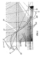
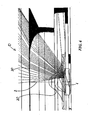
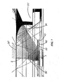
- FIGURES 1-7 illustrate lens 10 which is a preferred embodiment of the invention.
- Lens 10 is for directing light from a light emitter 1 which has an emitter axis 2 and defines an emitter plane 3.
- Lens 10 includes an emitter-adjacent base end 12 forming an opening to an inner cavity 14 surrounding emitter 1.
- Cavity 14 defines a space between emitter 1 and an inner-cavity surface 20 such that emitter light goes through air to enter lens material at inner-cavity surface 20. Because air and the lens material, which may be acrylic or other suitable material, have different refraction indexes resulting in bending of the light at inner-cavity surface 20.
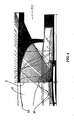
- FIGURE 2 best shows configuration of inner-cavity surface 20 which includes an axis-adjacent first inner region 21, a second inner region 22 spaced from first inner region 21, and a middle inner region 23 which joins first and second regions 21 and 22 and is substantially asymptotical to first and second inner regions 21 and 22.
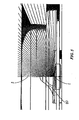
- FIGURES 1 and 3 best show that lens 10 further has an outer surface 30 which includes an axis-adjacent first output region 31, a second output region 32 spaced from axis-adjacent first output region 31, and a middle output region 33 joining first and second output regions 31 and 32.
- Each of output regions 31, 32 and 33 is configured for refracting the light from a corresponding one of inner regions 21, 22 and 23. Therefore, at outer surface 30 light from each inner region 21, 22 or 23 is refracted substantially without overlapping light rays from the other inner regions.
- outer surface 30 further includes a base-adjacent outer-surface region 34 which extends from second output region 32 and is substantially free from receiving any emitter light.
- Base-adjacent outer-surface region 34 is substantially orthogonal to emitter plane 3. It should be appreciated that, since the base-adjacent outer-surface substantially does not participate in distribution of emitter light, it may have any configuration dictated by positioning and mounting of the lens or other factors such as material or space conservation.
- FIGURE 2 best illustrates that axis-adjacent first inner region 21 is configured for refracting emitter light rays 210 which pass through axis-adjacent first inner region 21 away from axis 2. This provides a broader distribution of the light emitted about axis and allows to enlarge the size of first output region 31 to achieve better refraction of light 210 outside lens 10.
- Light 210 received by the axis-adjacent first inner region 21 has the highest intensity. This is because typically the highest illumination intensity of the emitter light is concentrated about axis 2.
- axis-adjacent inner region 21 allows for dispersion of such light 210 over a larger area. This improves uniformity of illumination intensity and substantially decreases a so-called "hot-spot" effect in a plot of illumination intensity distribution.
- FIGURE 2 further illustrates that axis-adjacent first inner region 21 is substantially cross-sectionally concave.
- second inner region 22 is configured for refracting emitter light rays toward the axis. It is seen in FIGURE 2 that second inner region 22 is substantially cross-sectionally convex. Second inner region moves light 220, which mostly includes light emitted within about 30° from emitter plane 3, away from base-adjacent outer-surface region 34. As can be seen in FIGURE 1 , base-adjacent outer-surface region 34 is surrounded by structures 50 may serve to secure lens 10 with respect to emitter 1 or be a shield blocking emitter light from going in an undesirable direction. As a result, any light that would arrive at the base-adjacent region 34 would be blocked by such structures 50 and would be eventually lost.
- each one output region of outer surface 30 receives light which arrives at substantially narrow sector of angles. This, coupled with improved efficiency which eliminates the need for bending axis-adjacent light for side illumination, simplifies the configuration of that output region of outer surface 30 for refraction of such light in a desired direction and, therefore, decreases a probability of an irregularity impact on the light-output direction.
- middle inner region 23 is positioned with respect to emitter 1 to refract light away from axis 2 by progressively lesser amounts at positions progressively closer to the base-adjacent inner region.
- middle inner region 23 is cross-sectionally linear. In other words, middle inner region 23 is of substantially truncated conical shape.
- axis-adjacent first output region 31 is configured for receiving emitter light rays 210 from axis-adjacent first inner region 21 and further refracting them away from axis 2.
- Second output region 32 is configured for receiving emitter light rays 220 from second inner region 22 and refracting them substantially away from axis 27.
- Middle output region 33 is configured for receiving emitter light rays 230 from middle inner region 23 and refracting them substantially away from axis 2.
- outer surface 30 is just an exemplary configuration. Outer surface 30 can have other configurations which would be dictated by an intended illumination pattern.
- Second inner region 22 terminates before reaching emitter plane 3.
- Inner-cavity surface 20 further includes a base-adjacent inner region 24 extending from second inner region 22.
- Base-adjacent inner region 24 is substantially orthogonal to emitter plane 3 and is oriented for substantially non-refracted passing through of light 240 emitted between second inner region 22 and emitter plane 3.
- Lens 10 further includes a peripheral inner surface 40 which receives light 240 from base-adjacent inner region 24.
- Peripheral inner surface 40 is configured for total internal reflection (TIR) of light 240 toward emitter axis 2. Thus, light 240 is retrieved from lens 10 for useful illumination rather than being lost.
- Peripheral inner surface 40 is formed by a peripheral cavity 41 extending from base end 12. As best seen in FIGURE 2 , peripheral inner surface 41 is configured for TIR of light rays 240 before they enter peripheral cavity 41.
- FIGURE 1 shows inner-cavity surface 20 substantially rotationally symmetrical.
- Peripheral cavity 41 and peripheral inner surface 40 are also substantially rotationally symmetrical.
- the embodiment illustrated in FIGURE 1 further shows outer surface 30 as substantially rotationally symmetrical such that lens 10 has a substantially annular cross-section in a plane substantially parallel to emitter plane 3.
- the inner and outer surfaces can have shapes that result in substantially oval or ovoid cross-section made in a plane substantially parallel to the emitter plane. In other words, these surfaces may have symmetries other than rotational.
- the inventive lens may be shaped without a symmetry and have asymmetrical surfaces.
Landscapes
- Physics & Mathematics (AREA)
- General Physics & Mathematics (AREA)
- Optics & Photonics (AREA)
- Lenses (AREA)
- Led Device Packages (AREA)
- Non-Portable Lighting Devices Or Systems Thereof (AREA)
Claims (12)
- Linse (10) zur Verbreitung von Licht von einem Lichtemitter (1), der eine Emitterachse (2) aufweist und eine Emitterebene (3) definiert, mit:einem emitternahen Unterteilende (12), das eine Öffnung zu einem inneren Hohlraum (14) bildet, der dazu eingerichtet ist, den Emitter (1) zu umgeben; undeiner inneren Hohlraumoberfläche (20), die (a) einen im Querschnitt konkaven achsennahen ersten Innenbereich (21) umfasst, der dazu eingerichtet ist, Emitterlichtstrahlen (210) weg von der Achse zu brechen, (b) einen im Querschnitt konvexen zweiten Innenbereich (22) umfasst, der von dem ersten Innenbereich (21) beabstandet ist und dazu eingerichtet ist, Emitterlichtstrahlen (220) zu der Achse hin zu brechen,dadurch gekennzeichnet, dass
die innere Hohlraumoberfläche (20) des Weiteren (c) einen im Querschnitt linearen mittleren Innenbereich (23) umfasst, der sich an den ersten Innenbereich (21) und zweiten Innenbereich (22) anschließt und im Querschnitt asymptotisch dazu ist, wobei der mittlere Innenbereich (23) bezüglich des Emitters (1) angeordnet ist, um Licht (230) von der Achse (2) mit zunehmend geringeren Mengen an Positionen zu brechen, die zunehmend näher an dem zweiten Innenbereich (22) liegen; und
dass die Linse (10) des Weiteren eine äußere Oberfläche (30) aufweist, die dazu eingerichtet ist, das Licht von jedem der Innenbereiche (21, 22, 23) zu brechen. - Linse (10) nach Anspruch 1, wobei die äußere Oberfläche (30) Ausgangsbereiche (31, 32, 33) aufweist, die jeweils konfiguriert sind, um das Licht (210, 220, 230) von einem entsprechenden der Innenbereiche (21, 22, 23) zu brechen, so dass Licht von jedem Innenbereich (21, 22, 23) an der äußeren Oberfläche (30) empfangen wird, ohne mit dem Licht der anderen Innenbereiche zu überlappen.
- Linse (10) nach Anspruch 2, wobei die Ausgangsbereiche (31, 32, 33) der äußeren Oberfläche (30) umfassen:einen achsennahen ersten Ausgangsbereich (31), der dazu eingerichtet ist, Emitterlichtstrahlen (210) von dem achsennahen ersten Innenbereich (21) zu empfangen und diese von der Achse (2) weg zu brechen;einen zweiten Ausgangsbereich (32), der von dem ersten Ausgangsbereich (31) beabstandet ist und dazu eingerichtet ist, Emitterlichtstrahlen (230) von dem zweiten Innenbereich (22) zu empfangen und sie im Wesentlichen weg von der Achse (2) zu brechen; undeinen mittleren Ausgangsbereich (33), der den ersten Ausgangsbereich (31) und den zweiten Ausgangsbereich (32) verbindet und dazu eingerichtet ist, Emitterlichtstrahlen (230) von dem mittleren Innenbereich (23) zu empfangen und sie im Wesentlichen weg von der Achse (2) zu brechen.
- Linse (10) nach Anspruch 3, wobei die äußere Oberfläche (30) des Weiteren einen unterteilnahen äußeren Oberflächenbereich (34) aufweist, der sich von dem zweiten Ausgangsbereich (2) erstreckt und im Wesentlichen frei davon ist, Emitterlicht zu empfangen.
- Linse nach Anspruch 4, wobei der unterteilnahe äußere Oberflächenbereich (34) im Wesentlichen orthogonal zu der Emitterebene (3) ist.
- Linse (10) nach Anspruch 2, wobei die innere Hohlraumoberfläche (20) im Wesentlichen rotationssymmetrisch ist.
- Linse nach Anspruch 6, wobei die äußere Oberfläche (30) im Wesentlichen derart rotationssymmetrisch ist, so dass die Linse (10) einen im Wesentlichen kreisförmigen Querschnitt in einer Ebene aufweist, die im Wesentlichen parallel zu der Emitterebene (3) ist.
- Linse nach Anspruch 1, wobei der zweite Innenbereich (22) endet, bevor er die Emitterebene (3) erreicht.
- Linse (10) nach Anspruch 8, wobei die innere Hohlraumoberfläche (20) des Weiteren einen unterteilnahen Innenbereich (24) aufweist, der sich von dem zweiten Innenbereich (22) erstreckt und derart eingerichtet ist, dass die Lichtstrahlen (240), die zwischen dem zweiten Innenbereich (22) und der Emitterebene (3) ausgesendet werden, im Wesentlichen frei von Brechung durch den unterteilnahen Innenbereich (24) hindurch treten.
- Linse (10) nach Anspruch 9, die des Weiteren eine umgebende Innenfläche (40) umfasst, die Licht (240) von dem unterteilnahen Innenbereich (24) empfängt, wobei die umgebende Innenoberfläche (40) dazu eingerichtet ist, dieses Licht (240) im Wege einer Totalreflexion hin zu der Emitterachse (2) zu reflektieren.
- Linse (10) nach Anspruch 8, die des Weiteren eine umgebende Innenoberfläche (40) aufweist, um Licht (240) zu empfangen, das zwischen der unterteilnahen inneren Oberfläche (24) und der Emitterebene (3) emittiert wird, wobei die innere Oberfläche (40) dazu eingerichtet ist, solches Licht (240) hin zu der Emitterachse (2) im Wege einer Totalreflexion zu reflektieren.
- Linse (10) nach Anspruch 10 oder 11, wobei die umgebende innere Oberfläche (40) durch einen umlaufenden Hohlraum (41) gebildet ist, der sich von dem Unterteilende (12) erstreckt, wobei die umgebende innere Oberfläche (40) dazu eingerichtet ist, die Lichtstrahlen (240) total zu reflektieren, bevor sie in den umfänglichen Hohlraum (41) eintreten.
Applications Claiming Priority (2)
| Application Number | Priority Date | Filing Date | Title |
|---|---|---|---|
| US12/431,308 US9217854B2 (en) | 2009-04-28 | 2009-04-28 | Lens with controlled light refraction |
| PCT/US2010/000932 WO2010126560A1 (en) | 2009-04-28 | 2010-03-29 | Lens with controlled light refraction |
Publications (3)
| Publication Number | Publication Date |
|---|---|
| EP2425178A1 EP2425178A1 (de) | 2012-03-07 |
| EP2425178A4 EP2425178A4 (de) | 2013-11-27 |
| EP2425178B1 true EP2425178B1 (de) | 2016-08-24 |
Family
ID=42991897
Family Applications (1)
| Application Number | Title | Priority Date | Filing Date |
|---|---|---|---|
| EP10770040.3A Active EP2425178B1 (de) | 2009-04-28 | 2010-03-29 | Linse mit gesteuerter lichtbrechung |
Country Status (9)
| Country | Link |
|---|---|
| US (1) | US9217854B2 (de) |
| EP (1) | EP2425178B1 (de) |
| CN (1) | CN102414505B (de) |
| AU (1) | AU2010242080A1 (de) |
| BR (1) | BRPI1009866A2 (de) |
| CA (1) | CA2756155A1 (de) |
| MX (1) | MX2011010155A (de) |
| NZ (1) | NZ595165A (de) |
| WO (1) | WO2010126560A1 (de) |
Families Citing this family (37)
| Publication number | Priority date | Publication date | Assignee | Title |
|---|---|---|---|---|
| US10119662B2 (en) | 2009-04-28 | 2018-11-06 | Cree, Inc. | Lens with controlled light refraction |
| US10422503B2 (en) | 2009-10-30 | 2019-09-24 | Ideal Industries Lighting Llc | One-piece multi-lens optical member and method of manufacture |
| US9915409B2 (en) | 2015-02-19 | 2018-03-13 | Cree, Inc. | Lens with textured surface facilitating light diffusion |
| US9416926B2 (en) | 2009-04-28 | 2016-08-16 | Cree, Inc. | Lens with inner-cavity surface shaped for controlled light refraction |
| USD673307S1 (en) | 2011-05-12 | 2012-12-25 | Cooper Technologies Company | Light bar |
| JP5744646B2 (ja) * | 2011-06-29 | 2015-07-08 | 三菱電機株式会社 | 映像表示装置 |
| EP4242516B1 (de) | 2011-12-02 | 2026-02-25 | Seoul Semiconductor Co., Ltd. | Lichtemittierendes modul und linse |
| US10047930B2 (en) * | 2011-12-02 | 2018-08-14 | Seoul Semiconductor Co., Ltd. | Light emitting module and lens |
| US10408429B2 (en) | 2012-02-29 | 2019-09-10 | Ideal Industries Lighting Llc | Lens for preferential-side distribution |
| US9541257B2 (en) | 2012-02-29 | 2017-01-10 | Cree, Inc. | Lens for primarily-elongate light distribution |
| US9541258B2 (en) | 2012-02-29 | 2017-01-10 | Cree, Inc. | Lens for wide lateral-angle distribution |
| TWI470167B (zh) * | 2012-03-02 | 2015-01-21 | 具外部透鏡之光源裝置及光源系統 | |
| USD697664S1 (en) * | 2012-05-07 | 2014-01-14 | Cree, Inc. | LED lens |
| USD737499S1 (en) * | 2012-07-13 | 2015-08-25 | Asahi Rubber Inc. | Lens for light-emitting diode |
| US8974077B2 (en) | 2012-07-30 | 2015-03-10 | Ultravision Technologies, Llc | Heat sink for LED light source |
| US9134007B2 (en) * | 2012-11-06 | 2015-09-15 | Darwin Precisions Corporation | Light source device |
| KR20140104716A (ko) * | 2013-02-21 | 2014-08-29 | 삼성전자주식회사 | 광원 모듈 및 이를 구비하는 조명 장치 |
| WO2014151688A1 (en) * | 2013-03-15 | 2014-09-25 | Cree, Inc. | Lens with controlled light refraction |
| US9920901B2 (en) | 2013-03-15 | 2018-03-20 | Cree, Inc. | LED lensing arrangement |
| USD718490S1 (en) * | 2013-03-15 | 2014-11-25 | Cree, Inc. | LED lens |
| US10400984B2 (en) | 2013-03-15 | 2019-09-03 | Cree, Inc. | LED light fixture and unitary optic member therefor |
| KR101301206B1 (ko) * | 2013-05-01 | 2013-08-29 | 정해운 | 광학렌즈 |
| KR20150009860A (ko) * | 2013-07-17 | 2015-01-27 | 서울반도체 주식회사 | 광 확산 렌즈, 이를 구비한 발광 디바이스 |
| US9568768B2 (en) * | 2014-06-28 | 2017-02-14 | Radiant Choice Limited | Wavelength mixing optical component |
| JP6446202B2 (ja) * | 2014-08-22 | 2018-12-26 | 日立アプライアンス株式会社 | 広角度拡散光学系及びこれを用いた照明装置 |
| US9757912B2 (en) | 2014-08-27 | 2017-09-12 | Cree, Inc. | One-piece multi-lens optical member with ultraviolet inhibitor and method of manufacture |
| US9606229B2 (en) * | 2014-09-29 | 2017-03-28 | Honeywell International Inc. | Highly efficient NIR light distribution for imaging based intrusion detection |
| US10207440B2 (en) | 2014-10-07 | 2019-02-19 | Cree, Inc. | Apparatus and method for formation of multi-region articles |
| CN104390194B (zh) * | 2014-10-31 | 2017-04-26 | 深圳科宏健半导体照明有限公司 | 一种led光源的配光透镜及led灯具 |
| US9470394B2 (en) | 2014-11-24 | 2016-10-18 | Cree, Inc. | LED light fixture including optical member with in-situ-formed gasket and method of manufacture |
| KR102683383B1 (ko) | 2016-08-18 | 2024-07-15 | 서울반도체 주식회사 | 발광 모듈 및 렌즈 |
| JP6972609B2 (ja) * | 2017-03-28 | 2021-11-24 | セイコーエプソン株式会社 | 光射出装置および画像表示システム |
| US10697612B2 (en) * | 2018-05-02 | 2020-06-30 | Frank Shum | Light distribution for planar photonic component |
| KR102134078B1 (ko) * | 2018-11-29 | 2020-07-14 | 몰렉스 엘엘씨 | 발광 소자용 광 확산 렌즈 |
| FR3121308B1 (fr) | 2021-03-23 | 2023-12-22 | Appleton Grp Llc | Moteur de lumière à LED classé ZONE IEC 1 utilisant une optique pré-moulée |
| WO2022234349A1 (en) | 2021-05-03 | 2022-11-10 | Patil Santosh Keshav | Industrial high ceiling led luminaire |
| FR3135511B1 (fr) * | 2022-05-16 | 2024-07-19 | Appleton Grp Llc | Moteur de lumière à DEL certifié IEC ZONE utilisant une couche d’encapsulation pré-moulée et une feuille de métal |
Family Cites Families (49)
| Publication number | Priority date | Publication date | Assignee | Title |
|---|---|---|---|---|
| US1004585A (en) * | 1910-08-15 | 1911-10-03 | Multicolor Sign Co | Illuminated sign. |
| US1024695A (en) * | 1911-03-24 | 1912-04-30 | Hugh Mulholland | Illuminated sign. |
| US2254961A (en) * | 1937-08-21 | 1941-09-02 | George M Cressaty | Unitary lens system |
| US2212876A (en) * | 1938-11-05 | 1940-08-27 | Albert L Chauvet | Nonglare headlight |
| US2544413A (en) * | 1942-09-05 | 1951-03-06 | Optische Ind De Oude Deift Nv | Optical lens system comprising one or more aspherical refracting surfaces |
| US4186995A (en) * | 1978-03-30 | 1980-02-05 | Amp Incorporated | Light device, lens, and fiber optic package |
| SE423755B (sv) * | 1980-07-30 | 1982-05-24 | Optik Innovation Ab Oiab | Projektionsoptik |
| US4474437A (en) * | 1982-04-12 | 1984-10-02 | Gorenstein Marc V | Teaching aid for simulating gravitational bending of light |
| DE3229577A1 (de) * | 1982-08-07 | 1984-02-09 | Fa. Carl Zeiss, 7920 Heidenheim | Brillenlinse fuer stark fehlsichtige |
| NL8400152A (nl) * | 1984-01-18 | 1984-10-01 | Philips Nv | Werkwijze voor de vervaardiging van een optisch element, inrichting voor toepassing van de werkwijze en optisch element vervaardigd met de werkwijze. |
| US5302778A (en) * | 1992-08-28 | 1994-04-12 | Eastman Kodak Company | Semiconductor insulation for optical devices |
| US5650838A (en) * | 1995-05-04 | 1997-07-22 | Johnson & Johnson Vision Products, Inc. | Programmable smooth junctions on lenses |
| TW402856B (en) * | 1996-12-26 | 2000-08-21 | Palite Corp | LED illuminator |
| US6273596B1 (en) * | 1997-09-23 | 2001-08-14 | Teledyne Lighting And Display Products, Inc. | Illuminating lens designed by extrinsic differential geometry |
| JP3370612B2 (ja) * | 1998-09-14 | 2003-01-27 | 富士通株式会社 | 光強度変換素子、コリメートレンズ、対物レンズ及び光学装置 |
| US6547423B2 (en) * | 2000-12-22 | 2003-04-15 | Koninklijke Phillips Electronics N.V. | LED collimation optics with improved performance and reduced size |
| US6616299B2 (en) * | 2001-02-02 | 2003-09-09 | Gelcore Llc | Single optical element LED signal |
| US6598998B2 (en) * | 2001-05-04 | 2003-07-29 | Lumileds Lighting, U.S., Llc | Side emitting light emitting device |
| US6837605B2 (en) * | 2001-11-28 | 2005-01-04 | Osram Opto Semiconductors Gmbh | Led illumination system |
| US6679621B2 (en) * | 2002-06-24 | 2004-01-20 | Lumileds Lighting U.S., Llc | Side emitting LED and lens |
| US6896381B2 (en) * | 2002-10-11 | 2005-05-24 | Light Prescriptions Innovators, Llc | Compact folded-optics illumination lens |
| WO2005012951A2 (en) * | 2003-07-28 | 2005-02-10 | Light Prescriptions Innovators, Llc | Three-dimensional simultaneous multiple-surface method and free-form illumination-optics designed therefrom |
| CN1715980A (zh) * | 2004-07-02 | 2006-01-04 | 鸿富锦精密工业(深圳)有限公司 | 非球面镜片及其制造方法 |
| KR100638611B1 (ko) * | 2004-08-12 | 2006-10-26 | 삼성전기주식회사 | 다중 렌즈 발광 다이오드 |
| JP2006106109A (ja) * | 2004-09-30 | 2006-04-20 | Nikon Corp | 非球面レンズ、該非球面レンズを備えた光学装置 |
| KR100688767B1 (ko) * | 2004-10-15 | 2007-02-28 | 삼성전기주식회사 | Led 광원용 렌즈 |
| US7352011B2 (en) * | 2004-11-15 | 2008-04-01 | Philips Lumileds Lighting Company, Llc | Wide emitting lens for LED useful for backlighting |
| TWI317829B (en) * | 2004-12-15 | 2009-12-01 | Epistar Corp | Led illumination device and application thereof |
| US7731395B2 (en) * | 2005-01-26 | 2010-06-08 | Anthony International | Linear lenses for LEDs |
| KR101229874B1 (ko) * | 2005-04-22 | 2013-02-05 | 삼성디스플레이 주식회사 | 광학 렌즈와, 이를 갖는 광학 패키지, 백라이트 어셈블리및 표시장치 |
| KR100722590B1 (ko) * | 2005-08-30 | 2007-05-28 | 삼성전기주식회사 | 백라이트용 led 렌즈 |
| EP1768197A3 (de) * | 2005-09-27 | 2012-11-21 | LG Electronics Inc. | Leuchtdioden-Verpackung und Rückbeleuchtungseinheit |
| DE102005061798A1 (de) * | 2005-09-30 | 2007-04-05 | Osram Opto Semiconductors Gmbh | Beleuchtungsanordnung |
| US7391580B2 (en) * | 2005-11-14 | 2008-06-24 | Zeev Maresse | Ultra compact mono-bloc catadioptric imaging lens |
| US20080294254A1 (en) * | 2005-12-06 | 2008-11-27 | Cumming J Stuart | Intraocular lens |
| JP2007293979A (ja) * | 2006-04-24 | 2007-11-08 | Sony Corp | ソリッドイマージョンレンズとこれを用いた集光レンズ、光学ピックアップ装置及び光記録再生装置 |
| KR101286705B1 (ko) * | 2006-10-31 | 2013-07-16 | 삼성디스플레이 주식회사 | 백라이트 광원 및 광원용 렌즈 그리고 이를 포함하는백라이트 어셈블리 |
| US7607792B2 (en) * | 2006-12-22 | 2009-10-27 | Hong Kong Applieed Science and Technology Research Institute Co. LTd. | Light-emitting devices and lens therefor |
| KR100756174B1 (ko) * | 2007-02-20 | 2007-09-05 | 주식회사 세코닉스 | Led용 집광렌즈 |
| US20080198604A1 (en) * | 2007-02-20 | 2008-08-21 | Sekonix Co., Ltd. | Lighting apparatus using filter and condenser for led illumination |
| US7618163B2 (en) * | 2007-04-02 | 2009-11-17 | Ruud Lighting, Inc. | Light-directing LED apparatus |
| AU2008254676B2 (en) * | 2007-05-21 | 2012-03-22 | Illumination Management Solutions, Inc. | An improved LED device for wide beam generation and method of making the same |
| JP5213383B2 (ja) * | 2007-08-09 | 2013-06-19 | シャープ株式会社 | 発光装置およびこれを備える照明装置 |
| US7766509B1 (en) * | 2008-06-13 | 2010-08-03 | Lumec Inc. | Orientable lens for an LED fixture |
| EP2326870B1 (de) * | 2008-08-14 | 2017-01-25 | Cooper Technologies Company | Led-vorrichtungen für versetzte breitstrahlerzeugung |
| US7874703B2 (en) * | 2008-08-28 | 2011-01-25 | Dialight Corporation | Total internal reflection lens with base |
| US8339716B2 (en) * | 2008-12-03 | 2012-12-25 | Philip Premysler | Illumination lenses including light redistributing surfaces |
| CN101988644A (zh) * | 2009-07-31 | 2011-03-23 | 富准精密工业(深圳)有限公司 | 发光二极管模组 |
| US8348461B2 (en) * | 2009-10-30 | 2013-01-08 | Ruud Lighting, Inc. | LED apparatus and method for accurate lens alignment |
-
2009
- 2009-04-28 US US12/431,308 patent/US9217854B2/en active Active
-
2010
- 2010-03-29 CA CA2756155A patent/CA2756155A1/en not_active Abandoned
- 2010-03-29 CN CN201080018306.XA patent/CN102414505B/zh active Active
- 2010-03-29 WO PCT/US2010/000932 patent/WO2010126560A1/en not_active Ceased
- 2010-03-29 AU AU2010242080A patent/AU2010242080A1/en not_active Abandoned
- 2010-03-29 MX MX2011010155A patent/MX2011010155A/es active IP Right Grant
- 2010-03-29 BR BRPI1009866A patent/BRPI1009866A2/pt not_active IP Right Cessation
- 2010-03-29 EP EP10770040.3A patent/EP2425178B1/de active Active
- 2010-03-29 NZ NZ595165A patent/NZ595165A/en unknown
Also Published As
| Publication number | Publication date |
|---|---|
| CA2756155A1 (en) | 2010-11-04 |
| CN102414505A (zh) | 2012-04-11 |
| US9217854B2 (en) | 2015-12-22 |
| WO2010126560A1 (en) | 2010-11-04 |
| EP2425178A4 (de) | 2013-11-27 |
| CN102414505B (zh) | 2015-08-26 |
| MX2011010155A (es) | 2011-10-17 |
| BRPI1009866A2 (pt) | 2016-03-08 |
| AU2010242080A1 (en) | 2011-10-20 |
| NZ595165A (en) | 2014-03-28 |
| US20100271708A1 (en) | 2010-10-28 |
| EP2425178A1 (de) | 2012-03-07 |
Similar Documents
| Publication | Publication Date | Title |
|---|---|---|
| EP2425178B1 (de) | Linse mit gesteuerter lichtbrechung | |
| EP2435756B1 (de) | Linse mit gesteuerter rücklichtverwaltung | |
| US9416926B2 (en) | Lens with inner-cavity surface shaped for controlled light refraction | |
| US9689552B2 (en) | Multi-lens LED-array optic system | |
| US11629843B2 (en) | Optics for chip-on-board road and area lighting | |
| JP2020510969A (ja) | 導光体を備える照明器具 | |
| US10119662B2 (en) | Lens with controlled light refraction | |
| TWI479107B (zh) | 發光二極體光分配透鏡及其光源裝置 | |
| US11553566B2 (en) | Luminaire for emitting directional and non-directional light | |
| CN109073206B (zh) | 一种发光装置及手术灯 | |
| AU2013204682B2 (en) | Lens with controlled backlight management | |
| EP2834556B1 (de) | Optisches led-arraysystem mit mehreren linsen | |
| EP2971946B1 (de) | Linse mit gesteuerter lichtbrechung | |
| HK1164421A (en) | Lens with controlled light refraction | |
| HK1164979B (en) | Lens with controlled backlight management |
Legal Events
| Date | Code | Title | Description |
|---|---|---|---|
| PUAI | Public reference made under article 153(3) epc to a published international application that has entered the european phase |
Free format text: ORIGINAL CODE: 0009012 |
|
| 17P | Request for examination filed |
Effective date: 20111018 |
|
| AK | Designated contracting states |
Kind code of ref document: A1 Designated state(s): AT BE BG CH CY CZ DE DK EE ES FI FR GB GR HR HU IE IS IT LI LT LU LV MC MK MT NL NO PL PT RO SE SI SK SM TR |
|
| DAX | Request for extension of the european patent (deleted) | ||
| RAP1 | Party data changed (applicant data changed or rights of an application transferred) |
Owner name: CREE, INC. |
|
| A4 | Supplementary search report drawn up and despatched |
Effective date: 20131025 |
|
| RIC1 | Information provided on ipc code assigned before grant |
Ipc: G02B 17/08 20060101ALI20131021BHEP Ipc: F21V 17/02 20060101AFI20131021BHEP |
|
| 17Q | First examination report despatched |
Effective date: 20150904 |
|
| REG | Reference to a national code |
Ref country code: DE Ref legal event code: R079 Ref document number: 602010035825 Country of ref document: DE Free format text: PREVIOUS MAIN CLASS: F21V0017020000 Ipc: G02B0019000000 |
|
| RIC1 | Information provided on ipc code assigned before grant |
Ipc: G02B 19/00 20060101AFI20160215BHEP |
|
| GRAP | Despatch of communication of intention to grant a patent |
Free format text: ORIGINAL CODE: EPIDOSNIGR1 |
|
| INTG | Intention to grant announced |
Effective date: 20160330 |
|
| GRAS | Grant fee paid |
Free format text: ORIGINAL CODE: EPIDOSNIGR3 |
|
| GRAA | (expected) grant |
Free format text: ORIGINAL CODE: 0009210 |
|
| AK | Designated contracting states |
Kind code of ref document: B1 Designated state(s): AT BE BG CH CY CZ DE DK EE ES FI FR GB GR HR HU IE IS IT LI LT LU LV MC MK MT NL NO PL PT RO SE SI SK SM TR |
|
| REG | Reference to a national code |
Ref country code: GB Ref legal event code: FG4D |
|
| REG | Reference to a national code |
Ref country code: CH Ref legal event code: EP |
|
| REG | Reference to a national code |
Ref country code: AT Ref legal event code: REF Ref document number: 823589 Country of ref document: AT Kind code of ref document: T Effective date: 20160915 |
|
| REG | Reference to a national code |
Ref country code: IE Ref legal event code: FG4D |
|
| REG | Reference to a national code |
Ref country code: DE Ref legal event code: R096 Ref document number: 602010035825 Country of ref document: DE |
|
| REG | Reference to a national code |
Ref country code: LT Ref legal event code: MG4D |
|
| REG | Reference to a national code |
Ref country code: NL Ref legal event code: MP Effective date: 20160824 |
|
| REG | Reference to a national code |
Ref country code: AT Ref legal event code: MK05 Ref document number: 823589 Country of ref document: AT Kind code of ref document: T Effective date: 20160824 |
|
| PG25 | Lapsed in a contracting state [announced via postgrant information from national office to epo] |
Ref country code: HR Free format text: LAPSE BECAUSE OF FAILURE TO SUBMIT A TRANSLATION OF THE DESCRIPTION OR TO PAY THE FEE WITHIN THE PRESCRIBED TIME-LIMIT Effective date: 20160824 Ref country code: NL Free format text: LAPSE BECAUSE OF FAILURE TO SUBMIT A TRANSLATION OF THE DESCRIPTION OR TO PAY THE FEE WITHIN THE PRESCRIBED TIME-LIMIT Effective date: 20160824 Ref country code: IT Free format text: LAPSE BECAUSE OF FAILURE TO SUBMIT A TRANSLATION OF THE DESCRIPTION OR TO PAY THE FEE WITHIN THE PRESCRIBED TIME-LIMIT Effective date: 20160824 Ref country code: FI Free format text: LAPSE BECAUSE OF FAILURE TO SUBMIT A TRANSLATION OF THE DESCRIPTION OR TO PAY THE FEE WITHIN THE PRESCRIBED TIME-LIMIT Effective date: 20160824 Ref country code: LT Free format text: LAPSE BECAUSE OF FAILURE TO SUBMIT A TRANSLATION OF THE DESCRIPTION OR TO PAY THE FEE WITHIN THE PRESCRIBED TIME-LIMIT Effective date: 20160824 Ref country code: NO Free format text: LAPSE BECAUSE OF FAILURE TO SUBMIT A TRANSLATION OF THE DESCRIPTION OR TO PAY THE FEE WITHIN THE PRESCRIBED TIME-LIMIT Effective date: 20161124 |
|
| PG25 | Lapsed in a contracting state [announced via postgrant information from national office to epo] |
Ref country code: ES Free format text: LAPSE BECAUSE OF FAILURE TO SUBMIT A TRANSLATION OF THE DESCRIPTION OR TO PAY THE FEE WITHIN THE PRESCRIBED TIME-LIMIT Effective date: 20160824 Ref country code: GR Free format text: LAPSE BECAUSE OF FAILURE TO SUBMIT A TRANSLATION OF THE DESCRIPTION OR TO PAY THE FEE WITHIN THE PRESCRIBED TIME-LIMIT Effective date: 20161125 Ref country code: LV Free format text: LAPSE BECAUSE OF FAILURE TO SUBMIT A TRANSLATION OF THE DESCRIPTION OR TO PAY THE FEE WITHIN THE PRESCRIBED TIME-LIMIT Effective date: 20160824 Ref country code: AT Free format text: LAPSE BECAUSE OF FAILURE TO SUBMIT A TRANSLATION OF THE DESCRIPTION OR TO PAY THE FEE WITHIN THE PRESCRIBED TIME-LIMIT Effective date: 20160824 Ref country code: PT Free format text: LAPSE BECAUSE OF FAILURE TO SUBMIT A TRANSLATION OF THE DESCRIPTION OR TO PAY THE FEE WITHIN THE PRESCRIBED TIME-LIMIT Effective date: 20161226 Ref country code: SE Free format text: LAPSE BECAUSE OF FAILURE TO SUBMIT A TRANSLATION OF THE DESCRIPTION OR TO PAY THE FEE WITHIN THE PRESCRIBED TIME-LIMIT Effective date: 20160824 |
|
| PG25 | Lapsed in a contracting state [announced via postgrant information from national office to epo] |
Ref country code: RO Free format text: LAPSE BECAUSE OF FAILURE TO SUBMIT A TRANSLATION OF THE DESCRIPTION OR TO PAY THE FEE WITHIN THE PRESCRIBED TIME-LIMIT Effective date: 20160824 Ref country code: EE Free format text: LAPSE BECAUSE OF FAILURE TO SUBMIT A TRANSLATION OF THE DESCRIPTION OR TO PAY THE FEE WITHIN THE PRESCRIBED TIME-LIMIT Effective date: 20160824 |
|
| REG | Reference to a national code |
Ref country code: DE Ref legal event code: R097 Ref document number: 602010035825 Country of ref document: DE |
|
| PG25 | Lapsed in a contracting state [announced via postgrant information from national office to epo] |
Ref country code: SM Free format text: LAPSE BECAUSE OF FAILURE TO SUBMIT A TRANSLATION OF THE DESCRIPTION OR TO PAY THE FEE WITHIN THE PRESCRIBED TIME-LIMIT Effective date: 20160824 Ref country code: BG Free format text: LAPSE BECAUSE OF FAILURE TO SUBMIT A TRANSLATION OF THE DESCRIPTION OR TO PAY THE FEE WITHIN THE PRESCRIBED TIME-LIMIT Effective date: 20161124 Ref country code: SK Free format text: LAPSE BECAUSE OF FAILURE TO SUBMIT A TRANSLATION OF THE DESCRIPTION OR TO PAY THE FEE WITHIN THE PRESCRIBED TIME-LIMIT Effective date: 20160824 Ref country code: PL Free format text: LAPSE BECAUSE OF FAILURE TO SUBMIT A TRANSLATION OF THE DESCRIPTION OR TO PAY THE FEE WITHIN THE PRESCRIBED TIME-LIMIT Effective date: 20160824 Ref country code: DK Free format text: LAPSE BECAUSE OF FAILURE TO SUBMIT A TRANSLATION OF THE DESCRIPTION OR TO PAY THE FEE WITHIN THE PRESCRIBED TIME-LIMIT Effective date: 20160824 Ref country code: BE Free format text: LAPSE BECAUSE OF FAILURE TO SUBMIT A TRANSLATION OF THE DESCRIPTION OR TO PAY THE FEE WITHIN THE PRESCRIBED TIME-LIMIT Effective date: 20160824 Ref country code: CZ Free format text: LAPSE BECAUSE OF FAILURE TO SUBMIT A TRANSLATION OF THE DESCRIPTION OR TO PAY THE FEE WITHIN THE PRESCRIBED TIME-LIMIT Effective date: 20160824 |
|
| PLBE | No opposition filed within time limit |
Free format text: ORIGINAL CODE: 0009261 |
|
| STAA | Information on the status of an ep patent application or granted ep patent |
Free format text: STATUS: NO OPPOSITION FILED WITHIN TIME LIMIT |
|
| 26N | No opposition filed |
Effective date: 20170526 |
|
| PG25 | Lapsed in a contracting state [announced via postgrant information from national office to epo] |
Ref country code: SI Free format text: LAPSE BECAUSE OF FAILURE TO SUBMIT A TRANSLATION OF THE DESCRIPTION OR TO PAY THE FEE WITHIN THE PRESCRIBED TIME-LIMIT Effective date: 20160824 |
|
| REG | Reference to a national code |
Ref country code: CH Ref legal event code: PL |
|
| GBPC | Gb: european patent ceased through non-payment of renewal fee |
Effective date: 20170329 |
|
| PG25 | Lapsed in a contracting state [announced via postgrant information from national office to epo] |
Ref country code: MC Free format text: LAPSE BECAUSE OF FAILURE TO SUBMIT A TRANSLATION OF THE DESCRIPTION OR TO PAY THE FEE WITHIN THE PRESCRIBED TIME-LIMIT Effective date: 20160824 |
|
| REG | Reference to a national code |
Ref country code: IE Ref legal event code: MM4A |
|
| REG | Reference to a national code |
Ref country code: FR Ref legal event code: ST Effective date: 20171130 |
|
| PG25 | Lapsed in a contracting state [announced via postgrant information from national office to epo] |
Ref country code: LU Free format text: LAPSE BECAUSE OF NON-PAYMENT OF DUE FEES Effective date: 20170329 Ref country code: FR Free format text: LAPSE BECAUSE OF NON-PAYMENT OF DUE FEES Effective date: 20170331 |
|
| PG25 | Lapsed in a contracting state [announced via postgrant information from national office to epo] |
Ref country code: LI Free format text: LAPSE BECAUSE OF NON-PAYMENT OF DUE FEES Effective date: 20170331 Ref country code: IE Free format text: LAPSE BECAUSE OF NON-PAYMENT OF DUE FEES Effective date: 20170329 Ref country code: GB Free format text: LAPSE BECAUSE OF NON-PAYMENT OF DUE FEES Effective date: 20170329 Ref country code: CH Free format text: LAPSE BECAUSE OF NON-PAYMENT OF DUE FEES Effective date: 20170331 |
|
| PG25 | Lapsed in a contracting state [announced via postgrant information from national office to epo] |
Ref country code: MT Free format text: LAPSE BECAUSE OF NON-PAYMENT OF DUE FEES Effective date: 20170329 |
|
| PG25 | Lapsed in a contracting state [announced via postgrant information from national office to epo] |
Ref country code: HU Free format text: LAPSE BECAUSE OF FAILURE TO SUBMIT A TRANSLATION OF THE DESCRIPTION OR TO PAY THE FEE WITHIN THE PRESCRIBED TIME-LIMIT; INVALID AB INITIO Effective date: 20100329 |
|
| PG25 | Lapsed in a contracting state [announced via postgrant information from national office to epo] |
Ref country code: CY Free format text: LAPSE BECAUSE OF NON-PAYMENT OF DUE FEES Effective date: 20160824 |
|
| REG | Reference to a national code |
Ref country code: DE Ref legal event code: R082 Ref document number: 602010035825 Country of ref document: DE Representative=s name: KROHER - STROBEL RECHTS- UND PATENTANWAELTE PA, DE Ref country code: DE Ref legal event code: R081 Ref document number: 602010035825 Country of ref document: DE Owner name: IDEAL INDUSTRIES LIGHTING LLC, SYCAMORE, US Free format text: FORMER OWNER: CREE, INC., DURHAM, N.C., US Ref country code: DE Ref legal event code: R082 Ref document number: 602010035825 Country of ref document: DE Representative=s name: KROHER STROBEL RECHTS- UND PATENTANWAELTE PART, DE |
|
| PG25 | Lapsed in a contracting state [announced via postgrant information from national office to epo] |
Ref country code: MK Free format text: LAPSE BECAUSE OF FAILURE TO SUBMIT A TRANSLATION OF THE DESCRIPTION OR TO PAY THE FEE WITHIN THE PRESCRIBED TIME-LIMIT Effective date: 20160824 |
|
| PG25 | Lapsed in a contracting state [announced via postgrant information from national office to epo] |
Ref country code: TR Free format text: LAPSE BECAUSE OF FAILURE TO SUBMIT A TRANSLATION OF THE DESCRIPTION OR TO PAY THE FEE WITHIN THE PRESCRIBED TIME-LIMIT Effective date: 20160824 |
|
| PG25 | Lapsed in a contracting state [announced via postgrant information from national office to epo] |
Ref country code: IS Free format text: LAPSE BECAUSE OF FAILURE TO SUBMIT A TRANSLATION OF THE DESCRIPTION OR TO PAY THE FEE WITHIN THE PRESCRIBED TIME-LIMIT Effective date: 20161224 |
|
| REG | Reference to a national code |
Ref country code: DE Ref legal event code: R081 Ref document number: 602010035825 Country of ref document: DE Owner name: CREE LIGHTING USA LLC (N.D.GES.D. STAATES DELA, US Free format text: FORMER OWNER: IDEAL INDUSTRIES LIGHTING LLC, SYCAMORE, IL, US |
|
| PGFP | Annual fee paid to national office [announced via postgrant information from national office to epo] |
Ref country code: DE Payment date: 20250327 Year of fee payment: 16 |