EP2425166B1 - System zur identifikation von verbindungen von zusammenzufügenden elementen, die eine anordnung, insbesondere eine rohrleitung oder einen tank, bilden sollen, und in solch einem system verwendetes identifikationsverfahren - Google Patents
System zur identifikation von verbindungen von zusammenzufügenden elementen, die eine anordnung, insbesondere eine rohrleitung oder einen tank, bilden sollen, und in solch einem system verwendetes identifikationsverfahren Download PDFInfo
- Publication number
- EP2425166B1 EP2425166B1 EP10715275.3A EP10715275A EP2425166B1 EP 2425166 B1 EP2425166 B1 EP 2425166B1 EP 10715275 A EP10715275 A EP 10715275A EP 2425166 B1 EP2425166 B1 EP 2425166B1
- Authority
- EP
- European Patent Office
- Prior art keywords
- identification
- elements
- code
- join
- identifiers
- Prior art date
- Legal status (The legal status is an assumption and is not a legal conclusion. Google has not performed a legal analysis and makes no representation as to the accuracy of the status listed.)
- Active
Links
Images

Classifications
-
- G—PHYSICS
- G06—COMPUTING OR CALCULATING; COUNTING
- G06K—GRAPHICAL DATA READING; PRESENTATION OF DATA; RECORD CARRIERS; HANDLING RECORD CARRIERS
- G06K19/00—Record carriers for use with machines and with at least a part designed to carry digital markings
- G06K19/06—Record carriers for use with machines and with at least a part designed to carry digital markings characterised by the kind of the digital marking, e.g. shape, nature, code
- G06K19/06009—Record carriers for use with machines and with at least a part designed to carry digital markings characterised by the kind of the digital marking, e.g. shape, nature, code with optically detectable marking
-
- F—MECHANICAL ENGINEERING; LIGHTING; HEATING; WEAPONS; BLASTING
- F16—ENGINEERING ELEMENTS AND UNITS; GENERAL MEASURES FOR PRODUCING AND MAINTAINING EFFECTIVE FUNCTIONING OF MACHINES OR INSTALLATIONS; THERMAL INSULATION IN GENERAL
- F16L—PIPES; JOINTS OR FITTINGS FOR PIPES; SUPPORTS FOR PIPES, CABLES OR PROTECTIVE TUBING; MEANS FOR THERMAL INSULATION IN GENERAL
- F16L13/00—Non-disconnectable pipe joints, e.g. soldered, adhesive, or caulked joints
- F16L13/02—Welded joints
-
- G—PHYSICS
- G06—COMPUTING OR CALCULATING; COUNTING
- G06K—GRAPHICAL DATA READING; PRESENTATION OF DATA; RECORD CARRIERS; HANDLING RECORD CARRIERS
- G06K19/00—Record carriers for use with machines and with at least a part designed to carry digital markings
- G06K19/06—Record carriers for use with machines and with at least a part designed to carry digital markings characterised by the kind of the digital marking, e.g. shape, nature, code
- G06K19/067—Record carriers with conductive marks, printed circuits or semiconductor circuit elements, e.g. credit or identity cards also with resonating or responding marks without active components
- G06K19/07—Record carriers with conductive marks, printed circuits or semiconductor circuit elements, e.g. credit or identity cards also with resonating or responding marks without active components with integrated circuit chips
- G06K19/077—Constructional details, e.g. mounting of circuits in the carrier
- G06K19/07749—Constructional details, e.g. mounting of circuits in the carrier the record carrier being capable of non-contact communication, e.g. constructional details of the antenna of a non-contact smart card
- G06K19/07758—Constructional details, e.g. mounting of circuits in the carrier the record carrier being capable of non-contact communication, e.g. constructional details of the antenna of a non-contact smart card arrangements for adhering the record carrier to further objects or living beings, functioning as an identification tag
-
- F—MECHANICAL ENGINEERING; LIGHTING; HEATING; WEAPONS; BLASTING
- F16—ENGINEERING ELEMENTS AND UNITS; GENERAL MEASURES FOR PRODUCING AND MAINTAINING EFFECTIVE FUNCTIONING OF MACHINES OR INSTALLATIONS; THERMAL INSULATION IN GENERAL
- F16L—PIPES; JOINTS OR FITTINGS FOR PIPES; SUPPORTS FOR PIPES, CABLES OR PROTECTIVE TUBING; MEANS FOR THERMAL INSULATION IN GENERAL
- F16L2201/00—Special arrangements for pipe couplings
- F16L2201/60—Identification or marking
Definitions
- the present invention relates to a system for identifying junctions of elements to be assembled to form a mounting such as in particular a pipeline or a tank of hydrocarbon-based compound.
- the invention also relates to an identification method implemented in such a system.
- the invention finds important applications, particularly in the field of construction and monitoring of pipelines transmitting fluids such as gas, oil, water etc.
- These pipelines are formed by a tube assembly using welds that remain a delicate operation and must be done with care.
- the important problem is therefore to ensure the quality of the junctions between these tubes.
- welds of good quality by qualified persons and, on the other hand, during subsequent inspections, it is necessary to identify each of these welded joints and therefore it is necessary to identify them with certainty. .
- the identification of junctions is essential.
- the patent document CN192147 describes a system that detects welding quality and then transmits quality information via a data transmission network. However, this document gives no satisfactory description of means for identifying the location where the welding was performed.
- EP 1 262 272 A1 discloses a method and apparatus for automatically logging the assembly process of piping constructed by assembling pipe pieces together. Before assembly, data specific to the pieces of piping to be assembled are acquired, which is memorized in relation to a unique process identifier. From these specific data, it is also possible to generate a unique part identifier for each of the pipe pieces to be assembled. This identifier can be stored in relation to the process identifier.
- Another important application for the present invention is tank making for hydrocarbon compounds based on a sheet assembly.
- the invention proposes a system of the kind mentioned in the preamble which provides a simple and unambiguous identification of welded joints in order to facilitate the manufacturing, control and maintenance operations of a pipe network.
- -line or any other assembly such as tank and also assembly of beams.
- the system comprises the features defined in claim 1.
- reference numeral 10 represents a partial view of a pipe-line network formed of a set of elements, in this embodiment, tubes, connected together by means of welds.
- the set of tubes represented in this figure comprises the tubes 11, 12, 13 and 14.
- This lead is considered herein as a multi-ended tube.
- the branches are manufactured by molding, in particular, and in practice they are not likely to present leaks between the tubes constituting this derivation.
- junction J1 connects a first end of the tube 11 with a first end of the branch 15
- junction J2 connects a first end of the tube 12 with a second end of the branch 15 and the junction J3, a first end of the tube 13 with a third end of the branch 15
- junction J4 connects the second end of the tube 11 with a first end of the tube 14.
- these tubes are provided with identifiers. These identifiers can either be unique or multiple, an identifier that can be assigned to each tube end. This identifier is called a chamfer identifier.
- the tube 11 is provided with identifiers A1 and A2 at each of its ends
- the tube 12 is provided with the identifiers B1, B2 and the tube 13 with identifiers C1, C2.
- the branch 15 is provided with identifiers D1, D2 and D3.
- the tube 14 comprises, him, a single identifier M placed, for example, in the middle.
- Each of the identifiers mentioned is carrying an identification code referenced by the same letters as the identifiers but in lower case.
- junction identification system 20 formed to from an identifier reader 22 to read the codes contained in the different identifiers A1, A2, B1, B2, C1, C2, C3 and M.
- management device 25 to provide an identification code joining two conduits from the tube identification codes of said two tubes. This is done by a combining device 28.
- the trunk identification code is made available at the terminal 29.
- the identifier reader 22 comprises a reading head 31 for reading bar codes. It reads the code of the identifiers being in the form of barcodes. After reading the bar codes "a2" and “d1" identifiers of the tube 11 and the first end of the branch 15 located on either side of the junction J1, the combination device 28 determines the code identifying this junction J1 .
- This combination device can operate by concatenation of the two codes or perform other juxtaposition operation such as derivation of these codes to obtain another code by taking out characteristic parts of the codes.
- the tube 14 comprises a single tube identifier M affixed in the middle, for example, of this tube 14 intended to abut the tube 11 to thereby form the junction J4.
- the code of this junction will be formulated by a combination of the codes "m” and "al”.
- identifiers may also be in the form of RFID tags, that is to say radio-identification labels better known under the name Anglo-Saxon: "Radio Frequency Identification”.
- the system comprises an identifier reader comprising the barcode reading head 22 and an RFID tag reading head 32, as shown in FIG. figure 2 .
- the user must therefore choose the reading head to use according to the nature of the identifiers.
- the invention thus covers applications relating to these two types of identifiers in combination or in a separate manner and also covers any other type of identifiers considered separately or in combination.
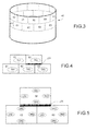
- the figure 3 shows another application of the invention which relates to the manufacture of hydrocarbon reservoir for example.
- the tank 45 is formed of a plurality of sheets 50, 51, 52, 60, 61, 62, 63,... These sheets are thus assembled to form this tank. They are arranged overlapping one another.
- the sheet 51 rests on both the sheet 61 and the sheet 62.
- the sheet 52 which adjoins the sheet 51 rests on the sheets 62 and 63.
- These sheets are welded together. To identify, it is necessary to combine the identification of the sheets involved in a weld.
- the weld J20 connecting the sheets 52 with the sheets 61 and 63 is identified by means of the identifiers thereof.
- the junction is identified by the respective codes t52, t61, t62 contained by the identifiers T52, T61, T62.
- the junction J20 can be identified by the concatenation of these codes. that is, "t52 t61 t62".
- the plates can be provided with assigned identifiers, each one at their side to provide a lateral code.
- These codes can be 151, u51, r51 and d51 for identifiers L51, U51, R51 respectively. and D51 assigned to the plate 51, 162, 62, 62 and 62 to the plate 61 and 163, 63, 63 and 63 to the plate 63.
- the code identifying the junction J20 then becomes: "u62 d52 u63"
- FIG. figure 6 Another example of application is the connection of beams or other profiles, as shown in FIG. figure 6 .
- FIG. figure 6 Another example of application is the connection of beams or other profiles, as shown in FIG. figure 6 .
- FIG. figure 6 several elements of beams 100, 110 111 and 112 are joined by a welded junction J100.
- identification codes p00, p10, p11, p12 contained in identifiers P00, P10, P11, P12 that can respectively carry the various beams 100, 110 111 and 112.
- the code identifier of the junction is of the form "p00, p10, p11, p12"
Landscapes
- Engineering & Computer Science (AREA)
- Physics & Mathematics (AREA)
- General Physics & Mathematics (AREA)
- Theoretical Computer Science (AREA)
- General Engineering & Computer Science (AREA)
- Computer Hardware Design (AREA)
- Microelectronics & Electronic Packaging (AREA)
- Mechanical Engineering (AREA)
- General Factory Administration (AREA)
- Pipeline Systems (AREA)
- Filling Or Discharging Of Gas Storage Vessels (AREA)
- Cosmetics (AREA)
Claims (11)
- System zur Identifikation von Verbindungen von zusammenzufügenden Elementen (11, 12, 13, 14, 15; 50, 51, 52, ....; 100, 110, 111, 112), die eine Anordnung (10), insbesondere eine Rohrleitung oder einen Tank bilden sollen, bei dem für jedes Element mindestens ein Kennzeichen (A2, B1, B2, C1, C2, C3 und M; T51, T52, ....; P00, P10, P11, P12) des Elements für einen Identifikationscode des Elements vorgesehen ist, wobei das System mit einem Gerät (22) zum Lesen des Kennzeichens des Elements und einer Verarbeitungsvorrichtung (25) versehen ist, dadurch gekennzeichnet, dass die Verarbeitungsvorrichtung (25) so angeordnet ist, um Identifikationscodes für die Verbindung zwischen den verbundenen Elementen ausgehend von den Identifikationscodes der verbundenen Elemente mittels einer Kombinationsvorrichtung (28) zu liefern.
- Identifikationssystem nach Anspruch 1, dadurch gekennzeichnet, dass die Kombinationsvorrichtung (28) mit einer Verknüpfung der Codes zur Identifikation der an der Verbindung beteiligten Elemente arbeitet, um den Code zur Identifikation der Verbindung zu bilden.
- System zur Identifikation nach Anspruch 1 oder 2, bei dem mindestens ein Element (14) ein einziges Rohrkennzeichen (M) aufweist, welches verwendet wird, um den Identifikationscode der Verbindung zu bilden.
- System zur Identifikation nach den Ansprüchen 1 bis 3, bei dem mindestens ein Element Kennzeichen des Rohrendes für einen Identifikationscode des Endes des betroffenen Elements an jedem der Enden der Elemente aufweist, um den Identifikationscode der Verbindung ausgehend von den Identifikationscodes des Elements oder des Endes zu bilden, die zu beiden Seiten der Verbindung gelegen sind.
- System zur Identifikation nach einem der Ansprüche 1 bis 4, bei dem die Kennzeichen aus einer Beschriftung vom Typ Strichcode bestehen, dadurch gekennzeichnet, dass das Gerät zum Lesen der Kennzeichen einen Strichcode-Lesekopf aufweist.
- System zur Identifikation nach einem der Ansprüche 1 bis 4, bei dem die Kennzeichen aus Etiketten vom Typ RFID sind, dadurch gekennzeichnet, dass der Kennzeichen-Leser einen Lesekopf für Codes auf RFID-Etiketten aufweist.
- System zur Identifikation nach einem der Ansprüche 1 bis 3, bei dem die Kennzeichen aus Beschriftungen vom Typ Strichcode und andere aus Etiketten vom Typ RFID bestehen, dadurch gekennzeichnet, dass das Kennzeichen-Lesegerät einen Strichcode-Lesekopf und einen Code-Lesekopf für RFID-Etiketten aufweist.
- System zur Identifikation nach einem der Ansprüche 1 bis 7, dadurch gekennzeichnet, dass die Elemente Rohre für Rohrleitungen sind.
- System zur Identifikation nach einem der Ansprüche 1 bis 7, dadurch gekennzeichnet, dass die Elemente Bleche (51, 52, ...) sind zur Bildung eines Tanks.
- System zur Identifikation nach einem der Ansprüche 1 bis 7, dadurch gekennzeichnet, dass die Elemente Stahlträger (100, 110, 111, 112) sind.
- Verfahren zur Identifikation ausgeführt in einem System nach einem der Ansprüche 1 bis 10, dadurch gekennzeichnet, dass es folgende Schritte aufweist:- Erfassen der Identifikationscodes von an einer Verbindung beteiligten Elementen untereinander,- Kombination der Identifikationscodes der Elemente und- Bereitstellung des Codes der Verbindung ausgehend von dem kombinierten Code.
Priority Applications (1)
| Application Number | Priority Date | Filing Date | Title |
|---|---|---|---|
| PL10715275T PL2425166T3 (pl) | 2009-04-29 | 2010-04-28 | System identyfikacji połączeń elementów do zmontowania, przeznaczonych do utworzenia zestawu, zwłaszcza takiego jak rurociąg lub zbiornik oraz sposób identyfikacji zastosowany w takim systemie |
Applications Claiming Priority (2)
| Application Number | Priority Date | Filing Date | Title |
|---|---|---|---|
| FR0952823A FR2945138B1 (fr) | 2009-04-29 | 2009-04-29 | Systeme d'identification de jonctions d'elements a assembler destines a former un montage tel que notamment un pipeline ou un reservoir et procede d'identification mis en oeuvre dans un tel systeme |
| PCT/EP2010/055728 WO2010125108A1 (fr) | 2009-04-29 | 2010-04-28 | Systeme d'identification de jonctions d'éléments a assembler destines a former un montage tel que notamment un pipeline ou un réservoir et procede d'identification mis en oeuvre dans un tel systeme |
Publications (2)
| Publication Number | Publication Date |
|---|---|
| EP2425166A1 EP2425166A1 (de) | 2012-03-07 |
| EP2425166B1 true EP2425166B1 (de) | 2013-09-18 |
Family
ID=41350715
Family Applications (1)
| Application Number | Title | Priority Date | Filing Date |
|---|---|---|---|
| EP10715275.3A Active EP2425166B1 (de) | 2009-04-29 | 2010-04-28 | System zur identifikation von verbindungen von zusammenzufügenden elementen, die eine anordnung, insbesondere eine rohrleitung oder einen tank, bilden sollen, und in solch einem system verwendetes identifikationsverfahren |
Country Status (12)
| Country | Link |
|---|---|
| US (1) | US9269033B2 (de) |
| EP (1) | EP2425166B1 (de) |
| CN (1) | CN102510968B (de) |
| AU (1) | AU2010243639B2 (de) |
| BR (1) | BRPI1011537B1 (de) |
| CA (1) | CA2760293C (de) |
| ES (1) | ES2438501T3 (de) |
| FR (1) | FR2945138B1 (de) |
| MY (1) | MY153383A (de) |
| PL (1) | PL2425166T3 (de) |
| RU (1) | RU2538942C2 (de) |
| WO (1) | WO2010125108A1 (de) |
Families Citing this family (5)
| Publication number | Priority date | Publication date | Assignee | Title |
|---|---|---|---|---|
| EP2610622A1 (de) | 2007-12-31 | 2013-07-03 | Oridion Medical 1987 Ltd. | Rohrprüfer |
| GB2518674B (en) | 2013-09-30 | 2015-08-19 | Cejn Ab | Tube with tag and method for servicing the tube |
| CN112561017A (zh) * | 2020-12-25 | 2021-03-26 | 东方电气集团科学技术研究院有限公司 | 一种蛇形管焊缝标识追溯系统 |
| US11692805B2 (en) | 2021-08-25 | 2023-07-04 | Saudi Arabian Oil Company | Identification system for tubulars |
| CN120576290B (zh) * | 2025-08-04 | 2025-10-03 | 宁波北仑吉帝汽车配件有限公司 | 多规格适配的新能源汽车冷却水快速接头装置 |
Family Cites Families (14)
| Publication number | Priority date | Publication date | Assignee | Title |
|---|---|---|---|---|
| GB2049994B (en) | 1979-05-21 | 1983-08-03 | Rca Corp | Method for assembly in a crt |
| GB2208310B (en) * | 1987-07-22 | 1991-09-18 | Andrew Palmer & Associates Lim | Improvements in or relating to the identification of pipeline sections |
| FR2682179B1 (fr) * | 1991-10-02 | 1993-11-12 | Framatome | Procede de reperage individuel des tubes d'un echangeur de chaleur. |
| FR2691666B1 (fr) * | 1992-06-01 | 1997-07-04 | Gaz De France | Procede pour souder bout a bout deux pieces plastiques a code d'identification, au moyen d'une machine d'electrosoudage a commande automatique. |
| DE10124999A1 (de) * | 2001-05-22 | 2002-12-12 | Pf Schweistechnologie Gmbh | Verfahren und Vorrichtung zum automatischen Protokollieren von Rohrnetz-Verbindungsvorgängen auf Basis von bauteilspezifischen Daten |
| GB2377584A (en) * | 2001-06-05 | 2003-01-15 | Andrew Richard Hiron | Position recording and relocation of buried installations |
| DK1532474T3 (da) * | 2002-07-18 | 2012-10-01 | Shell Int Research | Markering af rørforforbindelser |
| JP2005141337A (ja) * | 2003-11-05 | 2005-06-02 | Ojima Shisaku Kenkyusho:Kk | メンテナンス支援システム、メンテナンス支援方法、およびメンテナンス支援用プログラム |
| CN1547181A (zh) * | 2003-11-28 | 2004-11-17 | 攀钢集团北海钢管有限公司 | 一种标识钢管的方法 |
| DE202004014075U1 (de) * | 2004-09-10 | 2004-11-25 | Mainhart, Patrick | Sicherheitskennzeichnungssystem für Mehrschichtverbundrohre |
| US7293715B2 (en) * | 2004-12-16 | 2007-11-13 | Schlumberger Technology Corporation | Marking system and method |
| TW200719290A (en) * | 2005-11-01 | 2007-05-16 | Datadot Technology Ltd | Article marking system |
| CN1921427A (zh) | 2006-08-18 | 2007-02-28 | 上海工业自动化仪表研究所 | 焊接过程质量监控的无线数据采集和处理系统 |
| FR2910975B1 (fr) * | 2006-12-28 | 2009-04-24 | Faurecia Sieges Automobile | Detection de presence dans un assemblage d'au moins deux elements |
-
2009
- 2009-04-29 FR FR0952823A patent/FR2945138B1/fr not_active Expired - Fee Related
-
2010
- 2010-04-28 WO PCT/EP2010/055728 patent/WO2010125108A1/fr not_active Ceased
- 2010-04-28 AU AU2010243639A patent/AU2010243639B2/en active Active
- 2010-04-28 BR BRPI1011537-4A patent/BRPI1011537B1/pt active IP Right Grant
- 2010-04-28 PL PL10715275T patent/PL2425166T3/pl unknown
- 2010-04-28 EP EP10715275.3A patent/EP2425166B1/de active Active
- 2010-04-28 CN CN201080019125.9A patent/CN102510968B/zh active Active
- 2010-04-28 US US13/266,952 patent/US9269033B2/en active Active
- 2010-04-28 MY MYPI2011005153A patent/MY153383A/en unknown
- 2010-04-28 CA CA2760293A patent/CA2760293C/en active Active
- 2010-04-28 ES ES10715275.3T patent/ES2438501T3/es active Active
- 2010-04-28 RU RU2011148084/08A patent/RU2538942C2/ru active
Also Published As
| Publication number | Publication date |
|---|---|
| BRPI1011537B1 (pt) | 2019-11-05 |
| CN102510968B (zh) | 2014-12-24 |
| US9269033B2 (en) | 2016-02-23 |
| RU2538942C2 (ru) | 2015-01-10 |
| PL2425166T3 (pl) | 2014-02-28 |
| ES2438501T3 (es) | 2014-01-17 |
| BRPI1011537A2 (pt) | 2016-03-29 |
| RU2011148084A (ru) | 2013-06-10 |
| FR2945138A1 (fr) | 2010-11-05 |
| AU2010243639B2 (en) | 2016-03-31 |
| CN102510968A (zh) | 2012-06-20 |
| CA2760293A1 (fr) | 2010-11-04 |
| WO2010125108A1 (fr) | 2010-11-04 |
| AU2010243639A1 (en) | 2011-12-08 |
| FR2945138B1 (fr) | 2011-05-13 |
| EP2425166A1 (de) | 2012-03-07 |
| MY153383A (en) | 2015-01-29 |
| US20120091197A1 (en) | 2012-04-19 |
| CA2760293C (en) | 2018-04-03 |
Similar Documents
| Publication | Publication Date | Title |
|---|---|---|
| EP2425166B1 (de) | System zur identifikation von verbindungen von zusammenzufügenden elementen, die eine anordnung, insbesondere eine rohrleitung oder einen tank, bilden sollen, und in solch einem system verwendetes identifikationsverfahren | |
| EP3355019B1 (de) | Vorrichtung zur kühlung | |
| FR2818409A1 (fr) | Procede pour diviser des documents structures en plusieurs parties | |
| EP3250874B1 (de) | Wärmebatterie mit verkapseltem phasenumwandlungsmaterial | |
| EP3455574A1 (de) | Wärmebatterie mit verkapseltem phasenumwandlungsmaterial | |
| FR2812081A1 (fr) | Module d'echange de chaleur, notamment pour vehicule automobile, et procede de fabrication de ce module | |
| WO2016120283A1 (fr) | Batterie thermique à matériau à changement de phase encapsulé | |
| EP1068481B1 (de) | Zweiphasige wärmeaustauschvorrichtung | |
| EP2268992A1 (de) | Verfahren zur reparatur von plattenwärmetauschern | |
| WO2020065225A1 (fr) | Adaptateur pour collecteur d'un échangeur de chaleur | |
| EP2098773A1 (de) | Abzweigflansch, Abzweigvorrichtung umfassend ein Hauptrohr und besagter Abzweigsflansch, und Anschlussverfahren eines solchen Abzweigungsflansches durch Schweissen | |
| WO2016030097A1 (fr) | Boîte collectrice compacte pour un échangeur de chaleur | |
| EP2955765B1 (de) | Thermoelektrische Vorrichtung, thermoelektrisches Modul mit thermoelektrischer Vorrichtung und Verfahren zur Herstellung einer solchen Vorrichtung | |
| EP3555545A1 (de) | Wärmetauscher mit verstärkungsplatte | |
| WO2015091088A1 (fr) | Module sous-marin immergeable de production d'énergie électrique | |
| jabbar Radhi | La trahison et l’amour dans La Musica Deuxième de Marguerite DURAS | |
| EP3430341A1 (de) | Wärmetauscher und zugehöriges herstellungsverfahren | |
| FR3084740A1 (fr) | Echangeur de chaleur a materiau a changement de phase | |
| Desportes | La friction | |
| EP4042357A1 (de) | Architektur zur erzeugung von elektronischem geld zwischen einer vielzahl von monetären einrichtungen | |
| WO2020128352A1 (fr) | Echangeur der chaleur avec boite collectrice comportant une plaque de guidage | |
| SEXUEL | HARCELEMENT MORAL | |
| FR2648549A1 (fr) | Collecteur pour echangeur de chaleur du type tube-dans-tube | |
| FR3090844A1 (fr) | Boîte collectrice et échangeur thermique pour installation de refroidissement et/ou chauffage et/ou ventilation et/ou climatisation | |
| FR2759311A1 (fr) | Procede de fabrication d'un element annulaire pour convertisseur de couple |
Legal Events
| Date | Code | Title | Description |
|---|---|---|---|
| PUAI | Public reference made under article 153(3) epc to a published international application that has entered the european phase |
Free format text: ORIGINAL CODE: 0009012 |
|
| 17P | Request for examination filed |
Effective date: 20111105 |
|
| AK | Designated contracting states |
Kind code of ref document: A1 Designated state(s): AT BE BG CH CY CZ DE DK EE ES FI FR GB GR HR HU IE IS IT LI LT LU LV MC MK MT NL NO PL PT RO SE SI SK SM TR |
|
| DAX | Request for extension of the european patent (deleted) | ||
| REG | Reference to a national code |
Ref country code: DE Ref legal event code: R079 Ref document number: 602010010375 Country of ref document: DE Free format text: PREVIOUS MAIN CLASS: F16L0001000000 Ipc: G06K0019077000 |
|
| GRAP | Despatch of communication of intention to grant a patent |
Free format text: ORIGINAL CODE: EPIDOSNIGR1 |
|
| RIC1 | Information provided on ipc code assigned before grant |
Ipc: G06K 19/077 20060101AFI20130430BHEP Ipc: G06K 19/06 20060101ALI20130430BHEP |
|
| INTG | Intention to grant announced |
Effective date: 20130522 |
|
| GRAS | Grant fee paid |
Free format text: ORIGINAL CODE: EPIDOSNIGR3 |
|
| GRAA | (expected) grant |
Free format text: ORIGINAL CODE: 0009210 |
|
| AK | Designated contracting states |
Kind code of ref document: B1 Designated state(s): AT BE BG CH CY CZ DE DK EE ES FI FR GB GR HR HU IE IS IT LI LT LU LV MC MK MT NL NO PL PT RO SE SI SK SM TR |
|
| REG | Reference to a national code |
Ref country code: GB Ref legal event code: FG4D Free format text: NOT ENGLISH |
|
| REG | Reference to a national code |
Ref country code: CH Ref legal event code: EP |
|
| REG | Reference to a national code |
Ref country code: IE Ref legal event code: FG4D Free format text: LANGUAGE OF EP DOCUMENT: FRENCH |
|
| REG | Reference to a national code |
Ref country code: AT Ref legal event code: REF Ref document number: 633118 Country of ref document: AT Kind code of ref document: T Effective date: 20131015 |
|
| REG | Reference to a national code |
Ref country code: DE Ref legal event code: R096 Ref document number: 602010010375 Country of ref document: DE Effective date: 20131114 |
|
| REG | Reference to a national code |
Ref country code: NL Ref legal event code: T3 |
|
| REG | Reference to a national code |
Ref country code: ES Ref legal event code: FG2A Ref document number: 2438501 Country of ref document: ES Kind code of ref document: T3 Effective date: 20140117 |
|
| PG25 | Lapsed in a contracting state [announced via postgrant information from national office to epo] |
Ref country code: CY Free format text: LAPSE BECAUSE OF FAILURE TO SUBMIT A TRANSLATION OF THE DESCRIPTION OR TO PAY THE FEE WITHIN THE PRESCRIBED TIME-LIMIT Effective date: 20130814 Ref country code: HR Free format text: LAPSE BECAUSE OF FAILURE TO SUBMIT A TRANSLATION OF THE DESCRIPTION OR TO PAY THE FEE WITHIN THE PRESCRIBED TIME-LIMIT Effective date: 20130918 Ref country code: SE Free format text: LAPSE BECAUSE OF FAILURE TO SUBMIT A TRANSLATION OF THE DESCRIPTION OR TO PAY THE FEE WITHIN THE PRESCRIBED TIME-LIMIT Effective date: 20130918 Ref country code: LT Free format text: LAPSE BECAUSE OF FAILURE TO SUBMIT A TRANSLATION OF THE DESCRIPTION OR TO PAY THE FEE WITHIN THE PRESCRIBED TIME-LIMIT Effective date: 20130918 |
|
| REG | Reference to a national code |
Ref country code: NO Ref legal event code: T2 Effective date: 20130918 |
|
| REG | Reference to a national code |
Ref country code: LT Ref legal event code: MG4D |
|
| PG25 | Lapsed in a contracting state [announced via postgrant information from national office to epo] |
Ref country code: SI Free format text: LAPSE BECAUSE OF FAILURE TO SUBMIT A TRANSLATION OF THE DESCRIPTION OR TO PAY THE FEE WITHIN THE PRESCRIBED TIME-LIMIT Effective date: 20130918 Ref country code: FI Free format text: LAPSE BECAUSE OF FAILURE TO SUBMIT A TRANSLATION OF THE DESCRIPTION OR TO PAY THE FEE WITHIN THE PRESCRIBED TIME-LIMIT Effective date: 20130918 Ref country code: GR Free format text: LAPSE BECAUSE OF FAILURE TO SUBMIT A TRANSLATION OF THE DESCRIPTION OR TO PAY THE FEE WITHIN THE PRESCRIBED TIME-LIMIT Effective date: 20131219 Ref country code: LV Free format text: LAPSE BECAUSE OF FAILURE TO SUBMIT A TRANSLATION OF THE DESCRIPTION OR TO PAY THE FEE WITHIN THE PRESCRIBED TIME-LIMIT Effective date: 20130918 |
|
| REG | Reference to a national code |
Ref country code: PL Ref legal event code: T3 |
|
| PG25 | Lapsed in a contracting state [announced via postgrant information from national office to epo] |
Ref country code: CY Free format text: LAPSE BECAUSE OF FAILURE TO SUBMIT A TRANSLATION OF THE DESCRIPTION OR TO PAY THE FEE WITHIN THE PRESCRIBED TIME-LIMIT Effective date: 20130918 |
|
| PG25 | Lapsed in a contracting state [announced via postgrant information from national office to epo] |
Ref country code: EE Free format text: LAPSE BECAUSE OF FAILURE TO SUBMIT A TRANSLATION OF THE DESCRIPTION OR TO PAY THE FEE WITHIN THE PRESCRIBED TIME-LIMIT Effective date: 20130918 Ref country code: IS Free format text: LAPSE BECAUSE OF FAILURE TO SUBMIT A TRANSLATION OF THE DESCRIPTION OR TO PAY THE FEE WITHIN THE PRESCRIBED TIME-LIMIT Effective date: 20140118 Ref country code: SK Free format text: LAPSE BECAUSE OF FAILURE TO SUBMIT A TRANSLATION OF THE DESCRIPTION OR TO PAY THE FEE WITHIN THE PRESCRIBED TIME-LIMIT Effective date: 20130918 Ref country code: CZ Free format text: LAPSE BECAUSE OF FAILURE TO SUBMIT A TRANSLATION OF THE DESCRIPTION OR TO PAY THE FEE WITHIN THE PRESCRIBED TIME-LIMIT Effective date: 20130918 |
|
| REG | Reference to a national code |
Ref country code: DE Ref legal event code: R097 Ref document number: 602010010375 Country of ref document: DE |
|
| PG25 | Lapsed in a contracting state [announced via postgrant information from national office to epo] |
Ref country code: PT Free format text: LAPSE BECAUSE OF FAILURE TO SUBMIT A TRANSLATION OF THE DESCRIPTION OR TO PAY THE FEE WITHIN THE PRESCRIBED TIME-LIMIT Effective date: 20140120 |
|
| PLBE | No opposition filed within time limit |
Free format text: ORIGINAL CODE: 0009261 |
|
| STAA | Information on the status of an ep patent application or granted ep patent |
Free format text: STATUS: NO OPPOSITION FILED WITHIN TIME LIMIT |
|
| 26N | No opposition filed |
Effective date: 20140619 |
|
| PG25 | Lapsed in a contracting state [announced via postgrant information from national office to epo] |
Ref country code: DK Free format text: LAPSE BECAUSE OF FAILURE TO SUBMIT A TRANSLATION OF THE DESCRIPTION OR TO PAY THE FEE WITHIN THE PRESCRIBED TIME-LIMIT Effective date: 20130918 |
|
| REG | Reference to a national code |
Ref country code: DE Ref legal event code: R097 Ref document number: 602010010375 Country of ref document: DE Effective date: 20140619 |
|
| PG25 | Lapsed in a contracting state [announced via postgrant information from national office to epo] |
Ref country code: MC Free format text: LAPSE BECAUSE OF FAILURE TO SUBMIT A TRANSLATION OF THE DESCRIPTION OR TO PAY THE FEE WITHIN THE PRESCRIBED TIME-LIMIT Effective date: 20130918 Ref country code: LU Free format text: LAPSE BECAUSE OF FAILURE TO SUBMIT A TRANSLATION OF THE DESCRIPTION OR TO PAY THE FEE WITHIN THE PRESCRIBED TIME-LIMIT Effective date: 20140428 |
|
| REG | Reference to a national code |
Ref country code: CH Ref legal event code: PL |
|
| PG25 | Lapsed in a contracting state [announced via postgrant information from national office to epo] |
Ref country code: CH Free format text: LAPSE BECAUSE OF NON-PAYMENT OF DUE FEES Effective date: 20140430 Ref country code: LI Free format text: LAPSE BECAUSE OF NON-PAYMENT OF DUE FEES Effective date: 20140430 |
|
| PG25 | Lapsed in a contracting state [announced via postgrant information from national office to epo] |
Ref country code: MT Free format text: LAPSE BECAUSE OF FAILURE TO SUBMIT A TRANSLATION OF THE DESCRIPTION OR TO PAY THE FEE WITHIN THE PRESCRIBED TIME-LIMIT Effective date: 20130918 |
|
| REG | Reference to a national code |
Ref country code: FR Ref legal event code: PLFP Year of fee payment: 7 |
|
| PG25 | Lapsed in a contracting state [announced via postgrant information from national office to epo] |
Ref country code: SM Free format text: LAPSE BECAUSE OF FAILURE TO SUBMIT A TRANSLATION OF THE DESCRIPTION OR TO PAY THE FEE WITHIN THE PRESCRIBED TIME-LIMIT Effective date: 20130918 |
|
| PG25 | Lapsed in a contracting state [announced via postgrant information from national office to epo] |
Ref country code: RO Free format text: LAPSE BECAUSE OF FAILURE TO SUBMIT A TRANSLATION OF THE DESCRIPTION OR TO PAY THE FEE WITHIN THE PRESCRIBED TIME-LIMIT Effective date: 20130918 |
|
| PG25 | Lapsed in a contracting state [announced via postgrant information from national office to epo] |
Ref country code: BG Free format text: LAPSE BECAUSE OF FAILURE TO SUBMIT A TRANSLATION OF THE DESCRIPTION OR TO PAY THE FEE WITHIN THE PRESCRIBED TIME-LIMIT Effective date: 20130918 |
|
| PG25 | Lapsed in a contracting state [announced via postgrant information from national office to epo] |
Ref country code: TR Free format text: LAPSE BECAUSE OF FAILURE TO SUBMIT A TRANSLATION OF THE DESCRIPTION OR TO PAY THE FEE WITHIN THE PRESCRIBED TIME-LIMIT Effective date: 20130918 Ref country code: HU Free format text: LAPSE BECAUSE OF FAILURE TO SUBMIT A TRANSLATION OF THE DESCRIPTION OR TO PAY THE FEE WITHIN THE PRESCRIBED TIME-LIMIT; INVALID AB INITIO Effective date: 20100428 |
|
| REG | Reference to a national code |
Ref country code: FR Ref legal event code: PLFP Year of fee payment: 8 |
|
| REG | Reference to a national code |
Ref country code: FR Ref legal event code: PLFP Year of fee payment: 9 |
|
| PG25 | Lapsed in a contracting state [announced via postgrant information from national office to epo] |
Ref country code: MK Free format text: LAPSE BECAUSE OF FAILURE TO SUBMIT A TRANSLATION OF THE DESCRIPTION OR TO PAY THE FEE WITHIN THE PRESCRIBED TIME-LIMIT Effective date: 20130918 |
|
| PGFP | Annual fee paid to national office [announced via postgrant information from national office to epo] |
Ref country code: PL Payment date: 20230322 Year of fee payment: 14 |
|
| PGFP | Annual fee paid to national office [announced via postgrant information from national office to epo] |
Ref country code: NL Payment date: 20250319 Year of fee payment: 16 |
|
| PGFP | Annual fee paid to national office [announced via postgrant information from national office to epo] |
Ref country code: IE Payment date: 20250321 Year of fee payment: 16 |
|
| PGFP | Annual fee paid to national office [announced via postgrant information from national office to epo] |
Ref country code: NO Payment date: 20250321 Year of fee payment: 16 |
|
| PGFP | Annual fee paid to national office [announced via postgrant information from national office to epo] |
Ref country code: BE Payment date: 20250319 Year of fee payment: 16 |
|
| PGFP | Annual fee paid to national office [announced via postgrant information from national office to epo] |
Ref country code: FR Payment date: 20250319 Year of fee payment: 16 |
|
| PGFP | Annual fee paid to national office [announced via postgrant information from national office to epo] |
Ref country code: IT Payment date: 20250319 Year of fee payment: 16 |
|
| PGFP | Annual fee paid to national office [announced via postgrant information from national office to epo] |
Ref country code: DE Payment date: 20250319 Year of fee payment: 16 |
|
| PGFP | Annual fee paid to national office [announced via postgrant information from national office to epo] |
Ref country code: ES Payment date: 20250502 Year of fee payment: 16 |
|
| PGFP | Annual fee paid to national office [announced via postgrant information from national office to epo] |
Ref country code: AT Payment date: 20250321 Year of fee payment: 16 |
|
| PGFP | Annual fee paid to national office [announced via postgrant information from national office to epo] |
Ref country code: GB Payment date: 20260312 Year of fee payment: 17 |
|
| PG25 | Lapsed in a contracting state [announced via postgrant information from national office to epo] |
Ref country code: PL Free format text: LAPSE BECAUSE OF NON-PAYMENT OF DUE FEES Effective date: 20240428 |