EP2425150B1 - Device for connecting at least two belts - Google Patents
Device for connecting at least two belts Download PDFInfo
- Publication number
- EP2425150B1 EP2425150B1 EP10714190.5A EP10714190A EP2425150B1 EP 2425150 B1 EP2425150 B1 EP 2425150B1 EP 10714190 A EP10714190 A EP 10714190A EP 2425150 B1 EP2425150 B1 EP 2425150B1
- Authority
- EP
- European Patent Office
- Prior art keywords
- wall
- longitudinal wall
- longitudinal
- straps
- edge
- Prior art date
- Legal status (The legal status is an assumption and is not a legal conclusion. Google has not performed a legal analysis and makes no representation as to the accuracy of the status listed.)
- Active
Links
Images
Classifications
-
- F—MECHANICAL ENGINEERING; LIGHTING; HEATING; WEAPONS; BLASTING
- F16—ENGINEERING ELEMENTS AND UNITS; GENERAL MEASURES FOR PRODUCING AND MAINTAINING EFFECTIVE FUNCTIONING OF MACHINES OR INSTALLATIONS; THERMAL INSULATION IN GENERAL
- F16G—BELTS, CABLES, OR ROPES, PREDOMINANTLY USED FOR DRIVING PURPOSES; CHAINS; FITTINGS PREDOMINANTLY USED THEREFOR
- F16G3/00—Belt fastenings, e.g. for conveyor belts
- F16G3/16—Devices or machines for connecting driving-belts or the like
-
- Y—GENERAL TAGGING OF NEW TECHNOLOGICAL DEVELOPMENTS; GENERAL TAGGING OF CROSS-SECTIONAL TECHNOLOGIES SPANNING OVER SEVERAL SECTIONS OF THE IPC; TECHNICAL SUBJECTS COVERED BY FORMER USPC CROSS-REFERENCE ART COLLECTIONS [XRACs] AND DIGESTS
- Y10—TECHNICAL SUBJECTS COVERED BY FORMER USPC
- Y10T—TECHNICAL SUBJECTS COVERED BY FORMER US CLASSIFICATION
- Y10T24/00—Buckles, buttons, clasps, etc.
- Y10T24/16—Belt fasteners
- Y10T24/1604—Tighteners
-
- Y—GENERAL TAGGING OF NEW TECHNOLOGICAL DEVELOPMENTS; GENERAL TAGGING OF CROSS-SECTIONAL TECHNOLOGIES SPANNING OVER SEVERAL SECTIONS OF THE IPC; TECHNICAL SUBJECTS COVERED BY FORMER USPC CROSS-REFERENCE ART COLLECTIONS [XRACs] AND DIGESTS
- Y10—TECHNICAL SUBJECTS COVERED BY FORMER USPC
- Y10T—TECHNICAL SUBJECTS COVERED BY FORMER US CLASSIFICATION
- Y10T24/00—Buckles, buttons, clasps, etc.
- Y10T24/16—Belt fasteners
- Y10T24/1652—One piece
Definitions
- the invention relates to a device for connecting at least two straps according to the preamble of claim 1.
- a device for connecting at least two straps which has a bottom plate on which the straps, which are tapered for connection at their end sides, can be placed.
- US 2008/0060171 A1 a device for connecting two straps is known, which has two U-shaped clamping parts.
- the clamping parts can be connected to one another via a screw, wherein when this connection is made between the clamping parts, inserted ends of two straps are connected with each other under jamming.
- the invention has for its object to provide a device for connecting two straps of the type mentioned above, which is characterized by a cost-effective production and ease of use by reliably connecting ends of the straps.
- the straps under engagement of the connecting webs in the FixierausEnglishept and under fixing by the Hold-down means are inserted, the straps can be reliably connected with a few, easy to perform handles.
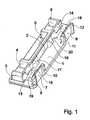
- Fig. 1 shows a perspective view of a first embodiment of a device according to the invention.
- the embodiment according to Fig. 1 is made of a hard elastic plastic and has a rectangular bottom plate 1 in this embodiment, on which on one side a single in Longitudinal direction of the bottom plate 1 extending and perpendicular from the bottom plate 1 raised longitudinal wall 2 is formed.
- the longitudinal wall 2 is arranged substantially centrally on the bottom plate 1.
- a number of longitudinal wall stiffening ribs 3, 4, 5, 6 are formed, which extend on one side of the longitudinal wall 2 in the transverse direction of the bottom plate 1 substantially to the edge of the bottom plate 1.
- a respective longitudinal wall stiffening rib 3, 6 are arranged at the opposite ends of the longitudinal wall 2, while the other two L josswandversteifungsrippen 4, 5 offset in a respective same distance from the end-side Lmikswandversteifungsrippen 3, 6 in the direction of the center of the longitudinal wall 2.
- edge walls 7, 8 On one end side of the bottom plate 1 arranged edge walls 7, 8, which are arranged at a distance in the transverse direction of the bottom plate 1 of the longitudinal wall 2.
- the edge walls 7, 8 are in each case pointing away from the longitudinal wall 2 by way of two edge wall reinforcing ribs 9, 10, 11, 12 which are arranged at the end, in order to increase the flexural rigidity of the edge walls 7, 8.
- the edge walls 7, 8 extend substantially over the end-side portions of the longitudinal wall 2, which are also stiffened by the Lssenswandversteifungsrippen 3, 4, 5, 6.
- the bottom plate 1 In the facing between the facing sides of the longitudinal wall 2 and the edge walls 7, 8 receiving areas, the bottom plate 1 for demoulding reasons each have a slide recess 19, 20 in order to demold the hold-down nose 13, 14, 15, 16.
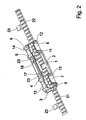
- Fig. 2 shows in a perspective view of the embodiment of a device according to the invention according to Fig. 1 with two straps 21, 22, which are formed with regularly spaced, transversely to the straps 21, 22 extending connecting webs 23.
- the connecting webs 23 are or were in Fig. 1 not shown parts attached, which are transported with the typically formed with a tooth structure straps 21, 22 or have been. In such manipulations, it is sometimes necessary to connect ends of straps 21, 22 with each other.
- the ends of the straps 21, 22 are inserted between the longitudinal wall 2 and the edge walls 7, 8 in a relevant intended use of the device according to the invention, that a connecting web 23 of a belt 21, 22 engages in each case a fixing recess 17, 18 and the straps 21, 22 after pressing between the hold down lugs 13, 14, 15, 16 between the bottom plate 1 and the bottom plate 1 facing abutment sides of the retaining tabs 13, 14, 15, 16 are arranged.
- the straps 21, 22 secured both against displacement in the longitudinal direction and against unintentional movement of the bottom plate 1 away.
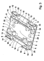
- Fig. 3 shows a perspective view of a second embodiment of a device according to the invention, which is substantially in a comparison with the embodiment according to Fig. 1 enlarged, approximately square base plate 1 with the same and arranged accordingly, but in number doubled structures as the embodiment according to Fig. 1 is equipped, wherein the edge wall stiffening ribs 9, 10, 11, 12 are arranged opposite to each other.
- the embodiment according to Fig. 3 formed with four formed by the two longitudinal walls 2 and the four peripheral walls 7, 8 receiving areas.
- the bottom plate 1 in the embodiment according to Fig. 3 is further formed with a number of mounting recesses 24, 25 to the bottom plate 1, for example, with a screw or a rivet on an in Fig. 3 not shown carrier part such as a belt drum for storing the straps 21, 22 to install in particular with attached parts.
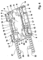
- Fig. 4 shows in a perspective view of the embodiment according to Fig. 3 with two straps 21, 22, which correspond to those in Fig. 2 shown straps 21, 22 are formed with connecting webs 23.
- the straps 21, 22 between lying on different edge sides of the bottom plate 1 Edge walls 7, 8 inserted so that they extend away on one side of the device according to the invention.
- a connection web 23 is arranged in a fixing recess 17, 18 in order to hold the straps 21, 22 in an arrangement adjacent to the bottom plate 1 via the hold-down lugs 13, 14, 15, 16.
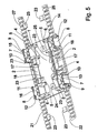
- Fig. 5 shows in a perspective view of the embodiment of a device according to the invention according to Fig. 3 with now four straps 21, 22, 26, 27, whose ends according to the arrangements according to Fig. 2 and according to Fig. 4 are inserted into the facing each other by the facing sides of the longitudinal walls 2 and the edge walls 7, 8 four receiving areas. In this way, two pairs of mutually parallel straps 21, 22, 26, 27 are now connected to each other.
Landscapes
- Engineering & Computer Science (AREA)
- General Engineering & Computer Science (AREA)
- Mechanical Engineering (AREA)
- Connection Of Plates (AREA)
- Clamps And Clips (AREA)
- Buckles (AREA)
- Joining Of Building Structures In Genera (AREA)
Description
Die Erfindung betrifft eine Vorrichtung zum Verbinden von wenigstens zwei Gurten gemäß dem Oberbegriff des Patentanspruches 1.The invention relates to a device for connecting at least two straps according to the preamble of
Aus
Aus
Der Erfindung liegt die Aufgabe zugrunde, eine Vorrichtung zum Verbinden von zwei Gurten der eingangs genannten Art anzugeben, die sich bei einer kostengünstigen Herstellung sowie einfachen Handhabung durch ein zuverlässiges Verbinden von Enden der Gurte auszeichnet.The invention has for its object to provide a device for connecting two straps of the type mentioned above, which is characterized by a cost-effective production and ease of use by reliably connecting ends of the straps.
Diese Aufgabe wird bei einer Vorrichtung zum Verbinden von wenigstens zwei Gurten der eingangs genannten Art mit den kennzeichnenden Merkmalen des Patentanspruches 1 gelöst.This object is achieved in a device for connecting at least two straps of the type mentioned above with the characterizing features of
Dadurch, dass bei der erfindungsgemäßen Vorrichtung lediglich ein einziges und damit zu einer kostengünstigen Vorrichtung führendes Teil vorhanden ist, in das die Gurte unter Eingriff der Anbindungsstege in die Fixierausnehmungen und unter Festlegen durch die Niederhaltemittel einfügbar sind, lassen sich die Gurte mit wenigen, einfach durchzuführenden Handgriffen zuverlässig miteinander verbinden.Due to the fact that in the device according to the invention only a single and therefore a cost effective device leading part is present, in which the straps under engagement of the connecting webs in the Fixierausnehmungen and under fixing by the Hold-down means are inserted, the straps can be reliably connected with a few, easy to perform handles.
Weitere zweckmäßige Ausgestaltungen der Erfindung sind Gegenstand der Unteransprüche.Further expedient embodiments of the invention are the subject of the dependent claims.
Weitere zweckmäßige Ausgestaltungen und Vorteile der Erfindung ergeben sich aus der nachfolgenden Beschreibung von Ausführungsbeispielen der Erfindung mit Bezug auf die Figuren der Zeichnung.Further expedient refinements and advantages of the invention will become apparent from the following description of embodiments of the invention with reference to the figures of the drawing.
Es zeigen:
- Fig. 1
- in einer perspektivischen Ansicht ein erstes Ausführungsbeispiel einer erfindungsgemäßen Vorrichtung zum Verbinden von zwei Gurten,
- Fig. 2
- in einer perspektivischen Ansicht das erste Ausführungsbeispiel gemäß
Fig. 1 mit bestimmungsgemäß eingefügten Enden von zwei Gurten, - Fig. 3
- in einer perspektivischen Ansicht ein zweites Ausführungsbeispiel einer erfindungsgemäßen Vorrichtung zum Verbinden von maximal vier Gurten,
- Fig. 4
- in einer perspektivischen Ansicht das zweite Ausführungsbeispiel gemäß
Fig. 3 mit zwei auf einer Seite eingefügten Enden von Gurten und - Fig. 5
- in einer perspektivischen Ansicht das zweite Ausführungsbeispiel gemäß
Fig. 3 mit vier eingefügten Enden von Gurten.
- Fig. 1
- in a perspective view of a first embodiment of an apparatus according to the invention for connecting two straps,
- Fig. 2
- in a perspective view of the first embodiment according to
Fig. 1 with properly inserted ends of two straps, - Fig. 3
- in a perspective view of a second embodiment of an inventive device for connecting a maximum of four straps,
- Fig. 4
- in a perspective view of the second embodiment according to
Fig. 3 with two ends of straps inserted on one side and - Fig. 5
- in a perspective view of the second embodiment according to
Fig. 3 with four inserted ends of straps.
Bei der Vorrichtung gemäß
Auf der den Längswandversteifungsrippen 3, 4, 5, 6 abgewandten Seite der Längswand 2 weist die erfindungsgemäße Vorrichtung gemäß
Aus
Schließlich ist aus
In den zwischen den aufeinander zu weisenden Seiten der Längswand 2 und der Randwände 7, 8 liegenden Aufnahmebereichen weist die Bodenplatte 1 aus entformungstechnischen Gründen jeweils eine Schieberausnehmung 19, 20 auf, um die Niederhaltenase 13, 14, 15, 16 zu entformen.In the facing between the facing sides of the
Hierzu sind bei einem diesbezüglichen bestimmungsgemäßen Einsatz der erfindungsgemäßen Vorrichtung die Enden der Gurte 21, 22 so zwischen die Längswand 2 und die Randwände 7, 8 eingefügt, dass ein Anbindungssteg 23 eines Gurtes 21, 22 in jeweils eine Fixierausnehmung 17, 18 eingreift und die Gurte 21, 22 nach Eindrücken zwischen die Niederhaltenasen 13, 14, 15, 16 zwischen der Bodenplatte 1 und den der Bodenplatte 1 zugewandten Anschlagseiten der Niederhaltenasen 13, 14, 15, 16 angeordnet sind. Damit sind die Gurte 21, 22 sowohl gegen Verschieben in Längsrichtung als auch gegen ein unbeabsichtigtes Bewegen von der Bodenplatte 1 weg gesichert.For this purpose, the ends of the
Die Bodenplatte 1 bei dem Ausführungsbeispiel gemäß
Claims (8)
- Device for connecting at least two belts (21, 22, 26, 27) which are provided with transversely oriented connecting webs (23), comprising a base plate (1), at least one longitudinal wall (2) extending in a longitudinal direction and rising above the base plate (1), and at least one edge wall (7, 8) opposing at least one, or each, of the longitudinal walls (2) and rising above the base plate (1), characterised in that at least one fixing recess (17, 18) is provided which, in operation, receives at least one connecting web (23) and is introduced into the, or one, longitudinal wall (2) and/or is introduced into the, or one, edge wall (7, 8) and wherein holding-down means (13, 14, 15, 16) is provided at the, or each, longitudinal wall (2) and/or at the, or each, edge wall (7, 8) for fixing a belt (21, 22, 26, 27).
- Device according to claim 1, characterised in that the holding-down means comprises a number of holding-down lugs (13, 14, 15, 16) which are provided between the, or each, longitudinal wall (2) and the, or each, edge wall (7, 8) opposing said respective longitudinal wall (2).
- Device according to claim 1 or claim 2, characterised in that on the side of the, or each, longitudinal wall (2) facing away from the, or each, edge wall (7, 8), at least one longitudinal wall stiffening rib (3, 4, 5, 6) is provided.
- Device according to one of the claims 1 to 3, characterised in that at least one edge wall stiffening rib (9, 10, 11, 12) is provided at the, or each, edge wall (7, 8) on the side facing away from the opposing longitudinal wall (2).
- Device according to one of the claims 1 to 4, characterised in that a single longitudinal wall (2) is provided which is arranged centrally on the base plate (1).
- Device according to one of the claims 1 to 4, characterised in that two longitudinal walls (2) are provided which are oriented parallel to one another.
- Device according to claim 5 or claim 6, characterised in that an edge wall (7, 8) is provided, in each case, at a distance in the transverse direction of the base plate (1) from the, or each, longitudinal wall (2).
- Device according to one of the claims 5 to 7, characterised in that the, or each, fixing recess (17, 18) is introduced into the longitudinal wall (2).
Applications Claiming Priority (2)
| Application Number | Priority Date | Filing Date | Title |
|---|---|---|---|
| DE200910019382 DE102009019382B4 (en) | 2009-04-29 | 2009-04-29 | Device for connecting at least two straps |
| PCT/EP2010/002234 WO2010124790A1 (en) | 2009-04-29 | 2010-04-10 | Device for connecting at least two belts |
Publications (2)
| Publication Number | Publication Date |
|---|---|
| EP2425150A1 EP2425150A1 (en) | 2012-03-07 |
| EP2425150B1 true EP2425150B1 (en) | 2013-11-06 |
Family
ID=42289842
Family Applications (1)
| Application Number | Title | Priority Date | Filing Date |
|---|---|---|---|
| EP10714190.5A Active EP2425150B1 (en) | 2009-04-29 | 2010-04-10 | Device for connecting at least two belts |
Country Status (5)
| Country | Link |
|---|---|
| US (1) | US8763208B2 (en) |
| EP (1) | EP2425150B1 (en) |
| DE (1) | DE102009019382B4 (en) |
| ES (1) | ES2436634T3 (en) |
| WO (1) | WO2010124790A1 (en) |
Families Citing this family (4)
| Publication number | Priority date | Publication date | Assignee | Title |
|---|---|---|---|---|
| DE102009019382B4 (en) * | 2009-04-29 | 2014-05-22 | A. Raymond Et Cie | Device for connecting at least two straps |
| TWI548578B (en) * | 2015-03-24 | 2016-09-11 | Chroma Ate Inc | Lifting equipment for electronic components |
| CA3020379C (en) * | 2016-04-26 | 2019-12-31 | Ib Verner DALGAARD-NIELSEN | Drive-belt connecting device designed for the tension-resistant connection of flat drive-belt end sections, drive belt, and conveying device equipped therewith |
| US10995821B2 (en) * | 2018-07-24 | 2021-05-04 | Gates Corporation | Belt clamp |
Family Cites Families (13)
| Publication number | Priority date | Publication date | Assignee | Title |
|---|---|---|---|---|
| US2069362A (en) * | 1935-01-30 | 1937-02-02 | Shaler Company | Fabricated belt splice and method of splicing the same |
| US2404041A (en) | 1944-12-06 | 1946-07-16 | Flexible Steel Lacing Co | Applicator for belt fasteners |
| US2430328A (en) * | 1945-01-31 | 1947-11-04 | Daniels Frederick Arthur | V-belt |
| DE3238266C2 (en) | 1982-10-15 | 1985-05-09 | Memminger Gmbh, 7290 Freudenstadt | Method and apparatus for connecting the ends of a fiber-reinforced plastic belt |
| SE469950B (en) * | 1992-02-28 | 1993-10-11 | Icl Data Ab | Joints for gear belts |
| US5391121A (en) * | 1994-01-05 | 1995-02-21 | Schramm; Michael R. | Method and apparatus for tool-less drive-belt installation |
| DE4417668A1 (en) | 1994-05-20 | 1995-11-23 | Memminger Iro Gmbh | Toothed belt for high tensile strength useful for driving equipment |
| DE19534932A1 (en) * | 1995-09-20 | 1997-03-27 | Marantec Antrieb Steuerung | Connection device for profiled drive means |
| US6896430B2 (en) * | 2002-10-23 | 2005-05-24 | Hewlett-Packard Development Company, L.P. | Compliant belt attach |
| US7810219B2 (en) | 2006-09-08 | 2010-10-12 | Designatronics, Inc. | Clamp for timing belt |
| WO2009049379A1 (en) * | 2007-10-19 | 2009-04-23 | Automatic Technology (Australia) Pty Ltd | Improvements relating to drive assemblies |
| DE102009019382B4 (en) * | 2009-04-29 | 2014-05-22 | A. Raymond Et Cie | Device for connecting at least two straps |
| US9347520B2 (en) * | 2011-12-01 | 2016-05-24 | Gates Corporation | Flat belt clamping system and method |
-
2009
- 2009-04-29 DE DE200910019382 patent/DE102009019382B4/en not_active Expired - Fee Related
-
2010
- 2010-04-10 US US13/201,129 patent/US8763208B2/en active Active
- 2010-04-10 ES ES10714190.5T patent/ES2436634T3/en active Active
- 2010-04-10 WO PCT/EP2010/002234 patent/WO2010124790A1/en not_active Ceased
- 2010-04-10 EP EP10714190.5A patent/EP2425150B1/en active Active
Also Published As
| Publication number | Publication date |
|---|---|
| ES2436634T3 (en) | 2014-01-03 |
| WO2010124790A1 (en) | 2010-11-04 |
| EP2425150A1 (en) | 2012-03-07 |
| US8763208B2 (en) | 2014-07-01 |
| US20120124780A1 (en) | 2012-05-24 |
| DE102009019382B4 (en) | 2014-05-22 |
| DE102009019382A1 (en) | 2013-01-17 |
Similar Documents
| Publication | Publication Date | Title |
|---|---|---|
| DE10218093B4 (en) | spinal implant | |
| DE19533845B4 (en) | Housing element for holding and protecting pipes, sewers, electrical lines and other elongated objects, in particular for motor vehicles | |
| DE10313866A1 (en) | snap construction | |
| WO1998007996A1 (en) | Line holder with an area for receiving a threaded bolt from either side | |
| DE102015206751B4 (en) | Releasable fastening arrangement of a bumper with a side wall or a fender of a motor vehicle | |
| DE102010011986B4 (en) | Hand-held tool | |
| EP2425150B1 (en) | Device for connecting at least two belts | |
| DE102006033642A1 (en) | Device for fixing a rectangular sensor to a support part | |
| EP2307744B1 (en) | Device for holding elements in a successive arrangement in a longitudinal direction | |
| EP2598761B1 (en) | Device for plugging onto a threaded bolt | |
| EP3347167B1 (en) | Stacking device for stacking paint and installation plugs | |
| DE202010004995U1 (en) | Fastener for fastening a first component to a second component | |
| EP2746696B1 (en) | Device for fixing solar modules to a support profile | |
| EP2097953B1 (en) | Device for fixing at least one coupling to a carrier part | |
| DE2720414C3 (en) | Fastening device for a guardrail mockery | |
| DE202013000005U1 (en) | Device for receiving a panel element | |
| EP0849478B1 (en) | Fixing elements magazine belt | |
| EP3826116B1 (en) | Plug connection system and use of a plug connection securing system in a plug connection system | |
| EP1800048B1 (en) | Device for joining pipe ends | |
| EP2738398B1 (en) | Device for detachably securing an attachment to a support with no play | |
| WO2004074696A1 (en) | Retaining clip | |
| EP2011668B1 (en) | Label holder | |
| DE102023106636A1 (en) | Cable holder | |
| DE102014210809B4 (en) | Vehicle with a device for connecting a side member to a cross member | |
| DE3007608C2 (en) | Device for holding objects |
Legal Events
| Date | Code | Title | Description |
|---|---|---|---|
| PUAI | Public reference made under article 153(3) epc to a published international application that has entered the european phase |
Free format text: ORIGINAL CODE: 0009012 |
|
| 17P | Request for examination filed |
Effective date: 20111129 |
|
| AK | Designated contracting states |
Kind code of ref document: A1 Designated state(s): AT BE BG CH CY CZ DE DK EE ES FI FR GB GR HR HU IE IS IT LI LT LU LV MC MK MT NL NO PL PT RO SE SI SK SM TR |
|
| DAX | Request for extension of the european patent (deleted) | ||
| GRAP | Despatch of communication of intention to grant a patent |
Free format text: ORIGINAL CODE: EPIDOSNIGR1 |
|
| INTG | Intention to grant announced |
Effective date: 20130412 |
|
| GRAS | Grant fee paid |
Free format text: ORIGINAL CODE: EPIDOSNIGR3 |
|
| GRAA | (expected) grant |
Free format text: ORIGINAL CODE: 0009210 |
|
| AK | Designated contracting states |
Kind code of ref document: B1 Designated state(s): AT BE BG CH CY CZ DE DK EE ES FI FR GB GR HR HU IE IS IT LI LT LU LV MC MK MT NL NO PL PT RO SE SI SK SM TR |
|
| REG | Reference to a national code |
Ref country code: GB Ref legal event code: FG4D Free format text: NOT ENGLISH |
|
| REG | Reference to a national code |
Ref country code: CH Ref legal event code: EP |
|
| REG | Reference to a national code |
Ref country code: AT Ref legal event code: REF Ref document number: 639716 Country of ref document: AT Kind code of ref document: T Effective date: 20131215 |
|
| REG | Reference to a national code |
Ref country code: IE Ref legal event code: FG4D Free format text: LANGUAGE OF EP DOCUMENT: GERMAN |
|
| REG | Reference to a national code |
Ref country code: DE Ref legal event code: R096 Ref document number: 502010005283 Country of ref document: DE Effective date: 20140102 |
|
| REG | Reference to a national code |
Ref country code: ES Ref legal event code: FG2A Ref document number: 2436634 Country of ref document: ES Kind code of ref document: T3 Effective date: 20140103 |
|
| REG | Reference to a national code |
Ref country code: NL Ref legal event code: VDEP Effective date: 20131106 |
|
| REG | Reference to a national code |
Ref country code: LT Ref legal event code: MG4D |
|
| PG25 | Lapsed in a contracting state [announced via postgrant information from national office to epo] |
Ref country code: NO Free format text: LAPSE BECAUSE OF FAILURE TO SUBMIT A TRANSLATION OF THE DESCRIPTION OR TO PAY THE FEE WITHIN THE PRESCRIBED TIME-LIMIT Effective date: 20140206 Ref country code: HR Free format text: LAPSE BECAUSE OF FAILURE TO SUBMIT A TRANSLATION OF THE DESCRIPTION OR TO PAY THE FEE WITHIN THE PRESCRIBED TIME-LIMIT Effective date: 20131106 Ref country code: FI Free format text: LAPSE BECAUSE OF FAILURE TO SUBMIT A TRANSLATION OF THE DESCRIPTION OR TO PAY THE FEE WITHIN THE PRESCRIBED TIME-LIMIT Effective date: 20131106 Ref country code: IS Free format text: LAPSE BECAUSE OF FAILURE TO SUBMIT A TRANSLATION OF THE DESCRIPTION OR TO PAY THE FEE WITHIN THE PRESCRIBED TIME-LIMIT Effective date: 20140306 Ref country code: LT Free format text: LAPSE BECAUSE OF FAILURE TO SUBMIT A TRANSLATION OF THE DESCRIPTION OR TO PAY THE FEE WITHIN THE PRESCRIBED TIME-LIMIT Effective date: 20131106 Ref country code: NL Free format text: LAPSE BECAUSE OF FAILURE TO SUBMIT A TRANSLATION OF THE DESCRIPTION OR TO PAY THE FEE WITHIN THE PRESCRIBED TIME-LIMIT Effective date: 20131106 Ref country code: SE Free format text: LAPSE BECAUSE OF FAILURE TO SUBMIT A TRANSLATION OF THE DESCRIPTION OR TO PAY THE FEE WITHIN THE PRESCRIBED TIME-LIMIT Effective date: 20131106 |
|
| PG25 | Lapsed in a contracting state [announced via postgrant information from national office to epo] |
Ref country code: LV Free format text: LAPSE BECAUSE OF FAILURE TO SUBMIT A TRANSLATION OF THE DESCRIPTION OR TO PAY THE FEE WITHIN THE PRESCRIBED TIME-LIMIT Effective date: 20131106 |
|
| PG25 | Lapsed in a contracting state [announced via postgrant information from national office to epo] |
Ref country code: PT Free format text: LAPSE BECAUSE OF FAILURE TO SUBMIT A TRANSLATION OF THE DESCRIPTION OR TO PAY THE FEE WITHIN THE PRESCRIBED TIME-LIMIT Effective date: 20140306 |
|
| REG | Reference to a national code |
Ref country code: DE Ref legal event code: R082 Ref document number: 502010005283 Country of ref document: DE |
|
| PG25 | Lapsed in a contracting state [announced via postgrant information from national office to epo] |
Ref country code: EE Free format text: LAPSE BECAUSE OF FAILURE TO SUBMIT A TRANSLATION OF THE DESCRIPTION OR TO PAY THE FEE WITHIN THE PRESCRIBED TIME-LIMIT Effective date: 20131106 |
|
| REG | Reference to a national code |
Ref country code: DE Ref legal event code: R097 Ref document number: 502010005283 Country of ref document: DE |
|
| PG25 | Lapsed in a contracting state [announced via postgrant information from national office to epo] |
Ref country code: PL Free format text: LAPSE BECAUSE OF FAILURE TO SUBMIT A TRANSLATION OF THE DESCRIPTION OR TO PAY THE FEE WITHIN THE PRESCRIBED TIME-LIMIT Effective date: 20131106 Ref country code: SK Free format text: LAPSE BECAUSE OF FAILURE TO SUBMIT A TRANSLATION OF THE DESCRIPTION OR TO PAY THE FEE WITHIN THE PRESCRIBED TIME-LIMIT Effective date: 20131106 Ref country code: RO Free format text: LAPSE BECAUSE OF FAILURE TO SUBMIT A TRANSLATION OF THE DESCRIPTION OR TO PAY THE FEE WITHIN THE PRESCRIBED TIME-LIMIT Effective date: 20131106 |
|
| PLBE | No opposition filed within time limit |
Free format text: ORIGINAL CODE: 0009261 |
|
| STAA | Information on the status of an ep patent application or granted ep patent |
Free format text: STATUS: NO OPPOSITION FILED WITHIN TIME LIMIT |
|
| PG25 | Lapsed in a contracting state [announced via postgrant information from national office to epo] |
Ref country code: DK Free format text: LAPSE BECAUSE OF FAILURE TO SUBMIT A TRANSLATION OF THE DESCRIPTION OR TO PAY THE FEE WITHIN THE PRESCRIBED TIME-LIMIT Effective date: 20131106 |
|
| 26N | No opposition filed |
Effective date: 20140807 |
|
| REG | Reference to a national code |
Ref country code: DE Ref legal event code: R097 Ref document number: 502010005283 Country of ref document: DE Effective date: 20140807 |
|
| PG25 | Lapsed in a contracting state [announced via postgrant information from national office to epo] |
Ref country code: MC Free format text: LAPSE BECAUSE OF FAILURE TO SUBMIT A TRANSLATION OF THE DESCRIPTION OR TO PAY THE FEE WITHIN THE PRESCRIBED TIME-LIMIT Effective date: 20131106 Ref country code: LU Free format text: LAPSE BECAUSE OF FAILURE TO SUBMIT A TRANSLATION OF THE DESCRIPTION OR TO PAY THE FEE WITHIN THE PRESCRIBED TIME-LIMIT Effective date: 20140410 |
|
| REG | Reference to a national code |
Ref country code: CH Ref legal event code: PL |
|
| REG | Reference to a national code |
Ref country code: IE Ref legal event code: MM4A |
|
| PG25 | Lapsed in a contracting state [announced via postgrant information from national office to epo] |
Ref country code: CH Free format text: LAPSE BECAUSE OF NON-PAYMENT OF DUE FEES Effective date: 20140430 Ref country code: LI Free format text: LAPSE BECAUSE OF NON-PAYMENT OF DUE FEES Effective date: 20140430 |
|
| PG25 | Lapsed in a contracting state [announced via postgrant information from national office to epo] |
Ref country code: SI Free format text: LAPSE BECAUSE OF FAILURE TO SUBMIT A TRANSLATION OF THE DESCRIPTION OR TO PAY THE FEE WITHIN THE PRESCRIBED TIME-LIMIT Effective date: 20131106 |
|
| PG25 | Lapsed in a contracting state [announced via postgrant information from national office to epo] |
Ref country code: IE Free format text: LAPSE BECAUSE OF NON-PAYMENT OF DUE FEES Effective date: 20140410 |
|
| PG25 | Lapsed in a contracting state [announced via postgrant information from national office to epo] |
Ref country code: MT Free format text: LAPSE BECAUSE OF FAILURE TO SUBMIT A TRANSLATION OF THE DESCRIPTION OR TO PAY THE FEE WITHIN THE PRESCRIBED TIME-LIMIT Effective date: 20131106 |
|
| REG | Reference to a national code |
Ref country code: FR Ref legal event code: PLFP Year of fee payment: 7 |
|
| PG25 | Lapsed in a contracting state [announced via postgrant information from national office to epo] |
Ref country code: SM Free format text: LAPSE BECAUSE OF FAILURE TO SUBMIT A TRANSLATION OF THE DESCRIPTION OR TO PAY THE FEE WITHIN THE PRESCRIBED TIME-LIMIT Effective date: 20131106 |
|
| REG | Reference to a national code |
Ref country code: AT Ref legal event code: MM01 Ref document number: 639716 Country of ref document: AT Kind code of ref document: T Effective date: 20150410 |
|
| PG25 | Lapsed in a contracting state [announced via postgrant information from national office to epo] |
Ref country code: BG Free format text: LAPSE BECAUSE OF FAILURE TO SUBMIT A TRANSLATION OF THE DESCRIPTION OR TO PAY THE FEE WITHIN THE PRESCRIBED TIME-LIMIT Effective date: 20131106 Ref country code: GR Free format text: LAPSE BECAUSE OF FAILURE TO SUBMIT A TRANSLATION OF THE DESCRIPTION OR TO PAY THE FEE WITHIN THE PRESCRIBED TIME-LIMIT Effective date: 20140207 Ref country code: CY Free format text: LAPSE BECAUSE OF FAILURE TO SUBMIT A TRANSLATION OF THE DESCRIPTION OR TO PAY THE FEE WITHIN THE PRESCRIBED TIME-LIMIT Effective date: 20131106 |
|
| PG25 | Lapsed in a contracting state [announced via postgrant information from national office to epo] |
Ref country code: BE Free format text: LAPSE BECAUSE OF FAILURE TO SUBMIT A TRANSLATION OF THE DESCRIPTION OR TO PAY THE FEE WITHIN THE PRESCRIBED TIME-LIMIT Effective date: 20140430 Ref country code: HU Free format text: LAPSE BECAUSE OF FAILURE TO SUBMIT A TRANSLATION OF THE DESCRIPTION OR TO PAY THE FEE WITHIN THE PRESCRIBED TIME-LIMIT; INVALID AB INITIO Effective date: 20100410 Ref country code: TR Free format text: LAPSE BECAUSE OF FAILURE TO SUBMIT A TRANSLATION OF THE DESCRIPTION OR TO PAY THE FEE WITHIN THE PRESCRIBED TIME-LIMIT Effective date: 20131106 |
|
| PG25 | Lapsed in a contracting state [announced via postgrant information from national office to epo] |
Ref country code: AT Free format text: LAPSE BECAUSE OF NON-PAYMENT OF DUE FEES Effective date: 20150410 |
|
| REG | Reference to a national code |
Ref country code: FR Ref legal event code: PLFP Year of fee payment: 8 |
|
| REG | Reference to a national code |
Ref country code: FR Ref legal event code: PLFP Year of fee payment: 9 |
|
| PG25 | Lapsed in a contracting state [announced via postgrant information from national office to epo] |
Ref country code: MK Free format text: LAPSE BECAUSE OF FAILURE TO SUBMIT A TRANSLATION OF THE DESCRIPTION OR TO PAY THE FEE WITHIN THE PRESCRIBED TIME-LIMIT Effective date: 20131106 |
|
| PGFP | Annual fee paid to national office [announced via postgrant information from national office to epo] |
Ref country code: IT Payment date: 20210427 Year of fee payment: 12 Ref country code: CZ Payment date: 20210412 Year of fee payment: 12 |
|
| PGFP | Annual fee paid to national office [announced via postgrant information from national office to epo] |
Ref country code: ES Payment date: 20210621 Year of fee payment: 12 Ref country code: GB Payment date: 20210422 Year of fee payment: 12 |
|
| PG25 | Lapsed in a contracting state [announced via postgrant information from national office to epo] |
Ref country code: CZ Free format text: LAPSE BECAUSE OF NON-PAYMENT OF DUE FEES Effective date: 20220410 |
|
| GBPC | Gb: european patent ceased through non-payment of renewal fee |
Effective date: 20220410 |
|
| PG25 | Lapsed in a contracting state [announced via postgrant information from national office to epo] |
Ref country code: GB Free format text: LAPSE BECAUSE OF NON-PAYMENT OF DUE FEES Effective date: 20220410 |
|
| PG25 | Lapsed in a contracting state [announced via postgrant information from national office to epo] |
Ref country code: IT Free format text: LAPSE BECAUSE OF NON-PAYMENT OF DUE FEES Effective date: 20220410 |
|
| REG | Reference to a national code |
Ref country code: ES Ref legal event code: FD2A Effective date: 20230626 |
|
| P01 | Opt-out of the competence of the unified patent court (upc) registered |
Effective date: 20230524 |
|
| PG25 | Lapsed in a contracting state [announced via postgrant information from national office to epo] |
Ref country code: ES Free format text: LAPSE BECAUSE OF NON-PAYMENT OF DUE FEES Effective date: 20220411 |
|
| PGFP | Annual fee paid to national office [announced via postgrant information from national office to epo] |
Ref country code: DE Payment date: 20250422 Year of fee payment: 16 |
|
| PGFP | Annual fee paid to national office [announced via postgrant information from national office to epo] |
Ref country code: FR Payment date: 20250425 Year of fee payment: 16 |