EP2425133B1 - Wind-power unit having a vertical turbine shaft - Google Patents
Wind-power unit having a vertical turbine shaft Download PDFInfo
- Publication number
- EP2425133B1 EP2425133B1 EP10770020.5A EP10770020A EP2425133B1 EP 2425133 B1 EP2425133 B1 EP 2425133B1 EP 10770020 A EP10770020 A EP 10770020A EP 2425133 B1 EP2425133 B1 EP 2425133B1
- Authority
- EP
- European Patent Office
- Prior art keywords
- supporting
- wind
- power unit
- turbine shaft
- unit according
- Prior art date
- Legal status (The legal status is an assumption and is not a legal conclusion. Google has not performed a legal analysis and makes no representation as to the accuracy of the status listed.)
- Not-in-force
Links
- 238000005096 rolling process Methods 0.000 claims description 3
- 239000000463 material Substances 0.000 claims description 2
- 230000007547 defect Effects 0.000 description 2
- 239000007779 soft material Substances 0.000 description 2
- 238000009987 spinning Methods 0.000 description 2
- 239000000725 suspension Substances 0.000 description 2
- 238000005452 bending Methods 0.000 description 1
- 230000002860 competitive effect Effects 0.000 description 1
- 230000000295 complement effect Effects 0.000 description 1
- 238000010276 construction Methods 0.000 description 1
- 230000007423 decrease Effects 0.000 description 1
- 230000003247 decreasing effect Effects 0.000 description 1
- -1 e.g. Polymers 0.000 description 1
- 230000001771 impaired effect Effects 0.000 description 1
- 239000002184 metal Substances 0.000 description 1
- 229920003023 plastic Polymers 0.000 description 1
- 239000004033 plastic Substances 0.000 description 1
- 229920002635 polyurethane Polymers 0.000 description 1
- 239000004814 polyurethane Substances 0.000 description 1
- 238000004804 winding Methods 0.000 description 1
Images
Classifications
-
- F—MECHANICAL ENGINEERING; LIGHTING; HEATING; WEAPONS; BLASTING
- F03—MACHINES OR ENGINES FOR LIQUIDS; WIND, SPRING, OR WEIGHT MOTORS; PRODUCING MECHANICAL POWER OR A REACTIVE PROPULSIVE THRUST, NOT OTHERWISE PROVIDED FOR
- F03D—WIND MOTORS
- F03D3/00—Wind motors with rotation axis substantially perpendicular to the air flow entering the rotor
- F03D3/005—Wind motors with rotation axis substantially perpendicular to the air flow entering the rotor the axis being vertical
- F03D3/011—Wind motors with rotation axis substantially perpendicular to the air flow entering the rotor the axis being vertical of the lift type, e.g. Darrieus or Musgrove
-
- F—MECHANICAL ENGINEERING; LIGHTING; HEATING; WEAPONS; BLASTING
- F03—MACHINES OR ENGINES FOR LIQUIDS; WIND, SPRING, OR WEIGHT MOTORS; PRODUCING MECHANICAL POWER OR A REACTIVE PROPULSIVE THRUST, NOT OTHERWISE PROVIDED FOR
- F03D—WIND MOTORS
- F03D13/00—Assembly, mounting or commissioning of wind motors; Arrangements specially adapted for transporting wind motor components
- F03D13/20—Arrangements for mounting or supporting wind motors; Masts or towers for wind motors
-
- F—MECHANICAL ENGINEERING; LIGHTING; HEATING; WEAPONS; BLASTING
- F03—MACHINES OR ENGINES FOR LIQUIDS; WIND, SPRING, OR WEIGHT MOTORS; PRODUCING MECHANICAL POWER OR A REACTIVE PROPULSIVE THRUST, NOT OTHERWISE PROVIDED FOR
- F03D—WIND MOTORS
- F03D80/00—Details, components or accessories not provided for in groups F03D1/00 - F03D17/00
- F03D80/70—Bearing or lubricating arrangements
- F03D80/703—Shaft bearings
-
- F—MECHANICAL ENGINEERING; LIGHTING; HEATING; WEAPONS; BLASTING
- F03—MACHINES OR ENGINES FOR LIQUIDS; WIND, SPRING, OR WEIGHT MOTORS; PRODUCING MECHANICAL POWER OR A REACTIVE PROPULSIVE THRUST, NOT OTHERWISE PROVIDED FOR
- F03D—WIND MOTORS
- F03D9/00—Adaptations of wind motors for special use; Combinations of wind motors with apparatus driven thereby; Wind motors specially adapted for installation in particular locations
- F03D9/20—Wind motors characterised by the driven apparatus
- F03D9/25—Wind motors characterised by the driven apparatus the apparatus being an electrical generator
-
- H—ELECTRICITY
- H02—GENERATION; CONVERSION OR DISTRIBUTION OF ELECTRIC POWER
- H02K—DYNAMO-ELECTRIC MACHINES
- H02K7/00—Arrangements for handling mechanical energy structurally associated with dynamo-electric machines, e.g. structural association with mechanical driving motors or auxiliary dynamo-electric machines
- H02K7/18—Structural association of electric generators with mechanical driving motors, e.g. with turbines
- H02K7/1807—Rotary generators
- H02K7/1823—Rotary generators structurally associated with turbines or similar engines
- H02K7/183—Rotary generators structurally associated with turbines or similar engines wherein the turbine is a wind turbine
-
- F—MECHANICAL ENGINEERING; LIGHTING; HEATING; WEAPONS; BLASTING
- F05—INDEXING SCHEMES RELATING TO ENGINES OR PUMPS IN VARIOUS SUBCLASSES OF CLASSES F01-F04
- F05B—INDEXING SCHEME RELATING TO WIND, SPRING, WEIGHT, INERTIA OR LIKE MOTORS, TO MACHINES OR ENGINES FOR LIQUIDS COVERED BY SUBCLASSES F03B, F03D AND F03G
- F05B2240/00—Components
- F05B2240/20—Rotors
- F05B2240/21—Rotors for wind turbines
- F05B2240/211—Rotors for wind turbines with vertical axis
- F05B2240/214—Rotors for wind turbines with vertical axis of the Musgrove or "H"-type
-
- F—MECHANICAL ENGINEERING; LIGHTING; HEATING; WEAPONS; BLASTING
- F05—INDEXING SCHEMES RELATING TO ENGINES OR PUMPS IN VARIOUS SUBCLASSES OF CLASSES F01-F04
- F05B—INDEXING SCHEME RELATING TO WIND, SPRING, WEIGHT, INERTIA OR LIKE MOTORS, TO MACHINES OR ENGINES FOR LIQUIDS COVERED BY SUBCLASSES F03B, F03D AND F03G
- F05B2240/00—Components
- F05B2240/50—Bearings
- F05B2240/54—Radial bearings
-
- Y—GENERAL TAGGING OF NEW TECHNOLOGICAL DEVELOPMENTS; GENERAL TAGGING OF CROSS-SECTIONAL TECHNOLOGIES SPANNING OVER SEVERAL SECTIONS OF THE IPC; TECHNICAL SUBJECTS COVERED BY FORMER USPC CROSS-REFERENCE ART COLLECTIONS [XRACs] AND DIGESTS
- Y02—TECHNOLOGIES OR APPLICATIONS FOR MITIGATION OR ADAPTATION AGAINST CLIMATE CHANGE
- Y02E—REDUCTION OF GREENHOUSE GAS [GHG] EMISSIONS, RELATED TO ENERGY GENERATION, TRANSMISSION OR DISTRIBUTION
- Y02E10/00—Energy generation through renewable energy sources
- Y02E10/70—Wind energy
- Y02E10/72—Wind turbines with rotation axis in wind direction
-
- Y—GENERAL TAGGING OF NEW TECHNOLOGICAL DEVELOPMENTS; GENERAL TAGGING OF CROSS-SECTIONAL TECHNOLOGIES SPANNING OVER SEVERAL SECTIONS OF THE IPC; TECHNICAL SUBJECTS COVERED BY FORMER USPC CROSS-REFERENCE ART COLLECTIONS [XRACs] AND DIGESTS
- Y02—TECHNOLOGIES OR APPLICATIONS FOR MITIGATION OR ADAPTATION AGAINST CLIMATE CHANGE
- Y02E—REDUCTION OF GREENHOUSE GAS [GHG] EMISSIONS, RELATED TO ENERGY GENERATION, TRANSMISSION OR DISTRIBUTION
- Y02E10/00—Energy generation through renewable energy sources
- Y02E10/70—Wind energy
- Y02E10/728—Onshore wind turbines
-
- Y—GENERAL TAGGING OF NEW TECHNOLOGICAL DEVELOPMENTS; GENERAL TAGGING OF CROSS-SECTIONAL TECHNOLOGIES SPANNING OVER SEVERAL SECTIONS OF THE IPC; TECHNICAL SUBJECTS COVERED BY FORMER USPC CROSS-REFERENCE ART COLLECTIONS [XRACs] AND DIGESTS
- Y02—TECHNOLOGIES OR APPLICATIONS FOR MITIGATION OR ADAPTATION AGAINST CLIMATE CHANGE
- Y02E—REDUCTION OF GREENHOUSE GAS [GHG] EMISSIONS, RELATED TO ENERGY GENERATION, TRANSMISSION OR DISTRIBUTION
- Y02E10/00—Energy generation through renewable energy sources
- Y02E10/70—Wind energy
- Y02E10/74—Wind turbines with rotation axis perpendicular to the wind direction
Definitions
- the present invention relates to a wind-power unit having a vertical turbine shaft that is radially mounted in bearings to a supporting pole.
- the invention also concerns an electric energy-consuming device, an electric mains as well as a use of the wind-power unit.
- Wind-power units with vertical shaft have increasingly developed to become a competitive alternative to wind-power units with horizontal shaft and have several advantages in relation to the same.
- There are different types of wind-power units with vertical shaft among others, units with a so-called H-rotor where the turbine blades are vertical.
- the present invention is primarily intended for H-rotor units but can also be applied to other kinds of wind-power units with vertical shaft.
- the turbine of the wind-power unit should be situated as high as possible.
- the turbine shaft is then connected with a generator arranged on the ground and having a unit shaft that by the upper end thereof is attached to the turbine shaft and by the lower end thereof is attached to the rotor of the generator.
- the generator may be directly arranged up at the turbine shaft.
- the diameter of the turbine shaft will be relatively large, often in the order of 50-200 cm, since often wind turbines of large dimensions are concerned. In certain special applications, it may for other reasons be expedient with a large diameter of the turbine shaft.
- a stable bearing mounting of the turbine shaft is required, and in the size range indicated, this involves a problem.
- Conventional bearings become very expensive. As they moreover are arranged at a high height, it becomes complicated to repair a bearing failure or other defects in the bearing mounting.
- the object of the present invention is to overcome this problem and accordingly provide support to the turbine shaft in the radial direction wherein the indicated drawbacks are obviated or at least reduced.
- WO 96/30647 discloses a support structure for a vertical axis wind turbine comprising a spinning tower supported for rotation about a fixed post by means of bearing wheels journaled by arms to the spinning tower, wherein the bearing wheels bear against the circumferential surface of the fixed post.
- a wind-power unit of the kind mentioned by way of introduction has the special features that the bearing mounting comprises at least one supporting device comprising at least three supporting components distributed in the circumferential direction with spacings between the supporting components in the circumferential direction, the total extension of which spacings in the circumferential direction exceeds half the circumference, and which supporting components abut against the turbine shaft and are connected with the supporting pole.
- the supporting devices replace the need of conventional bearings for the bearing mounting of the turbine shaft and eliminate thereby the problems associated with the same at the large dimensions that often are the case in this context.
- the supporting devices become considerably more inexpensive than conventional bearings. This constitutes a significant contribution to enhance the economical competitiveness of this kind of wind-power units.
- the invention also entails an improved operating economy in comparison with if conventional bearings would have been used, thanks to service and repair of possible defects being facilitated.
- the device for bearing mounting according to the invention has in addition a relatively low weight.
- the number of supporting components is 3-7.
- the total extension in the circumferential direction of the spacings is 1/2-3/4 of the circumference.
- each supporting component comprises at least one roller body arranged to abut against the turbine shaft.
- the roller body consists of a wheel.
- each supporting component comprises two wheels arranged on a carrying element, which carrying element is turnable around a vertical shaft between the two wheel shafts.
- Such a boogie-like supporting component provides a good centring of the turbine shaft between the supporting components and contributes to the fact that the supporting device gets a desired flexibility that allows a certain motion laterally of the turbine shaft without the bearing-mounting stability becoming impaired.
- each supporting component is resiliently pressed against the turbine shaft.
- the resilient suspension means therefore also lower requirements of precision in the mounting of the turbine.
- a leaf spring is arranged between the supporting components and the supporting pole.
- a cup spring is arranged between the supporting component and the supporting pole.
- a cup spring is another suitable alternative of the springing that in a simple way guarantees a suitable degree of springing.
- the cup spring may also be complementary to the leaf spring.
- each roller body has a rolling surface of a material that is softer than the rest of the roller body.
- the soft material is a plastic such as, e.g., polyurethane and the rest of the roller body may be of metal.
- the bearing mounting comprises two axially separated supporting devices.
- the stability and precision of the bearing mounting increase, particularly when the turbine shaft is long.
- the design with two supporting devices entails decreased lateral forces on the joint that connects the turbine shaft with the unit shaft.
- At least one of the supporting devices is arranged to be able to carry the axial force.
- the supporting pole has radially inwardly facing support surfaces with which each supporting device is connected, and the wind-power unit comprising a generator arranged at the lower end of the supporting pole and a unit shaft that rotationally fixedly connects the turbine shaft with the generator.
- the supporting device in accordance with the invention is particularly advantageous to use in such a type of wind-power units.
- the unit shaft is normally arranged inside the supporting pole, and therefore it is structurally suitable that also the turbine shaft extends into the mast, and is, in this way, thereby supported from outside from the supporting pole.
- the supporting pole has radially outwardly facing support surfaces with which each supporting device is connected, the turbine shaft is hollow, and each supporting device abuts against the inside of the turbine shaft.
- a generator is arranged inside the turbine shaft with the rotor attached to the inside of the turbine shaft and the stator attached to the supporting shaft.
- This embodiment is particularly suitable in contexts where the generated electric energy is consumed by electric devices adjacent to the supporting pole, for example when a telecommunications mast is concerned.
- the invention also concerns an energy-consuming device carried by a supporting pole, the supporting pole constituting the supporting pole of a wind-power unit according to the embodiment described next above of the invented wind-power unit and the wind-power unit being arranged to deliver energy to the electric energy-consuming device.
- An electric mains according to the invention has the special feature that it is connected to a wind-power unit according to the present invention, particularly according to anyone of the preferred embodiments of the same.
- the invention concerns a use of the invented wind-power unit, particularly according to anyone of the preferred embodiments of the same, for delivering energy to an electric mains.
- the invented electric mains and the invented use provide advantages of the corresponding kind as the invented wind-power unit, particularly according to anyone of the preferred embodiments of the same and that have been accounted for above.
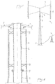
- Fig. 1 illustrates schematically a wind-power unit according to the invention with vertical shaft.
- the unit has a turbine 1 of the H-rotor type where a number of vertical turbine blades 5, for instance three, are connected to the turbine shaft 6 via stays 7.
- the turbine shaft 6 is connected to the shaft 4 of the unit by means of a rotationally fixed joint 9.
- the unit shaft 4 is at its lower end connected to the rotor of a generator 3.
- a supporting pole 2 surrounds the shaft 4.
- the supporting pole 2 is slightly conical. However, it may have another design, for example cylindrical, or conical over the greater part of its lower extension and cylindrical at the top.
- the supporting column may have an entirely surrounding wall or be made as a framework construction, and its cross-sectional shape may alternatively be a polygon.
- the unit shaft 4 is connected to the turbine shaft 6 by means of a rotationally fixed joint 9.
- the unit shaft 4 as well as the turbine shaft 6 is mounted in bearings in the supporting pole 2, and suitably both are formed as tubes, i.e., hollow.
- the generator 3 of the unit delivers energy to an electric mains 10.
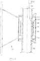
- Fig. 2 illustrates the upper part of the supporting pole 2 and the part of the turbine shaft 6 that is situated inside the same.
- the upper part of the supporting pole 2 is cylindrical.
- the turbine shaft 6 is radially mounted in bearings in the supporting pole 2 by means of two axially separated supporting devices 13.
- the turbine shaft 6 may also be axially mounted in bearings in the supporting pole 2 or its weight may be carried via the joint 9 with the unit shaft 4 by the axial bearing mounting of the unit shaft in the supporting pole 2.
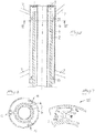
- the supporting device 13 is illustrated in more detail in Fig. 3 that is an enlarged section along the line III-III in Fig. 2 .
- the shown supporting device consists of three supporting components 15 uniformly distributed in the circumferential direction around the turbine shaft 6.
- Each supporting component 15 has two roller bodies 16 formed as wheels and that abut against the turbine shaft 6.
- the wheels 16 are mounted on a carrying element 17.
- the carrying element 17 is turnable around a suspension shaft 18 in a holder 19 that via a leaf spring 20 is attached to a supporting beam 21.
- the leaf spring 20 presses the supporting component 15 by a certain bias force against the turbine shaft 6, suitably in the order of 1 kN.
- the supporting beam 20 is anchored in the supporting pole 2.
- the supporting beam 21 may be formed with a thin cross-sectional dimension so that a certain spring action is achieved, the same functioning as a cup spring.
- the turbine shaft 6 also is axially mounted in bearings directly in the supporting pole 2, it is suitably made using a supporting device of the corresponding kind, but adapted to the axial force.
- a supporting device of the corresponding kind, but adapted to the axial force.
- FIG. 4 An example of the application of the supporting device upon the carrying of axial force is illustrated in Fig. 4 .
- the turbine shaft 6 is provided with a radial flange 30.
- three radially inwardly directed projections 31 are arranged uniformly distributed in the circumferential direction.
- a supporting component 35 is mounted on each projection.
- Said supporting components 35 may be formed in a simpler way than the corresponding supporting components 15 of the supporting device 33 shown in Fig. 3 for the radial bearing mounting.
- each supporting component consists of a simple yoke-shaped carrying element 37 attached to the respective projection 31 and that rotatably carries a wheel 36 in the carrying element 37 having an axially directed rotation axis.
- the supporting components may be resiliently formed with a spring action in the axial direction and also be provided with wheels boogie-mounted in pairs.
- the need therefor is smaller for the axial bearing mounting than for the radial bearing mounting.
- Fig. 5 illustrates an alternative embodiment example, in which the turbine shaft 6 is mounted in bearings on the outside of the supporting pole 2.
- the joint 9 between the turbine shaft 6 and the unit shaft 4 situated inside the supporting pole is arranged above the supporting pole 2. Also in this example, there are two axially separated supporting devices 13, each of which provided with three supporting components.
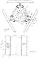
- Figs. 6 and 7 how the supporting components are arranged is seen in Figs. 6 and 7 , where Fig. 6 is a section along the line VI-VI in Fig. 5 .
- the supporting components 15, in this example three in number, are uniformly distributed in the circumferential direction. Each supporting component 15 rollingly abuts against the inside of the turbine shaft 6 and gets support by the outside of the supporting pole 2.
- Fig. 7 is a detailed view of an individual supporting component 15. As in the embodiment according to Fig. 3 , it is provided with two roller bodies 16 formed as wheels, which abut against the outside of the turbine shaft 6. The wheels 16 are correspondingly mounted to a carrying element 17 turnable around a shaft 18. Via a leaf spring 20 and a cup spring 21b, the supporting component 15 is attached to the outside of the supporting pole 2.
- Fig. 8 illustrates a telecommunications mast 102 that is provided with equipment and devices 110 that consume electric energy.
- a wind turbine 101 with vertical shaft is mounted to the outside of the telecommunications mast 102, and accordingly the telecommunications mast also serves as a supporting pole for the wind turbine 101.
- the turbine shaft 106 is mounted in bearings on the outside of the supporting pole 102 by means of the supporting devices 113 in a similar way as in the example shown in Figs. 5-7 .
- the generator 103 is arranged inside the turbine shaft 106 with the rotor 107 attached to the inside of the turbine shaft 106 and the stator 108 on the outside of the supporting pole 102. Via a line 109, the stator winding is connected to the electric energy-consuming devices 110.
- the presence of the generator 103 between the turbine shaft 106 and the supporting pole 102 makes the spacing between the same larger than in the embodiment example shown in Figs. 5-7 . In this case, it may therefore be suitable to provide the supporting pole 102 with one flange 140 for each supporting device 113, to which the supporting components thereof are attached. Alternatively, the leaf spring 20 in the embodiment example illustrated in Fig. 7 may be made longer and stiffer.
Landscapes
- Engineering & Computer Science (AREA)
- Life Sciences & Earth Sciences (AREA)
- Sustainable Development (AREA)
- Sustainable Energy (AREA)
- Chemical & Material Sciences (AREA)
- Combustion & Propulsion (AREA)
- Mechanical Engineering (AREA)
- General Engineering & Computer Science (AREA)
- Power Engineering (AREA)
- Wind Motors (AREA)
- Micro-Organisms Or Cultivation Processes Thereof (AREA)
Description
- The present invention relates to a wind-power unit having a vertical turbine shaft that is radially mounted in bearings to a supporting pole.
- The invention also concerns an electric energy-consuming device, an electric mains as well as a use of the wind-power unit.
- Wind-power units with vertical shaft have increasingly developed to become a competitive alternative to wind-power units with horizontal shaft and have several advantages in relation to the same. There are different types of wind-power units with vertical shaft, among others, units with a so-called H-rotor where the turbine blades are vertical. The present invention is primarily intended for H-rotor units but can also be applied to other kinds of wind-power units with vertical shaft.
- For an efficient utilization of the winds, the turbine of the wind-power unit should be situated as high as possible. The turbine shaft is then connected with a generator arranged on the ground and having a unit shaft that by the upper end thereof is attached to the turbine shaft and by the lower end thereof is attached to the rotor of the generator. Alternatively, the generator may be directly arranged up at the turbine shaft.
- Normally, the diameter of the turbine shaft will be relatively large, often in the order of 50-200 cm, since often wind turbines of large dimensions are concerned. In certain special applications, it may for other reasons be expedient with a large diameter of the turbine shaft. A stable bearing mounting of the turbine shaft is required, and in the size range indicated, this involves a problem. Conventional bearings become very expensive. As they moreover are arranged at a high height, it becomes complicated to repair a bearing failure or other defects in the bearing mounting.
- The object of the present invention is to overcome this problem and accordingly provide support to the turbine shaft in the radial direction wherein the indicated drawbacks are obviated or at least reduced.
-
WO 96/30647 - The object set forth is achieved by the invention by the fact that a wind-power unit of the kind mentioned by way of introduction has the special features that the bearing mounting comprises at least one supporting device comprising at least three supporting components distributed in the circumferential direction with spacings between the supporting components in the circumferential direction, the total extension of which spacings in the circumferential direction exceeds half the circumference, and which supporting components abut against the turbine shaft and are connected with the supporting pole.
- The supporting devices replace the need of conventional bearings for the bearing mounting of the turbine shaft and eliminate thereby the problems associated with the same at the large dimensions that often are the case in this context.
- The supporting devices become considerably more inexpensive than conventional bearings. This constitutes a significant contribution to enhance the economical competitiveness of this kind of wind-power units. The invention also entails an improved operating economy in comparison with if conventional bearings would have been used, thanks to service and repair of possible defects being facilitated. The device for bearing mounting according to the invention has in addition a relatively low weight.
- Suitably, the number of supporting components is 3-7. Suitably, the total extension in the circumferential direction of the spacings is 1/2-3/4 of the circumference.
- According to a preferred embodiment, each supporting component comprises at least one roller body arranged to abut against the turbine shaft.
- This entails low friction and little wear. Suitably, the roller body consists of a wheel.
- According to an additional preferred embodiment, each supporting component comprises two wheels arranged on a carrying element, which carrying element is turnable around a vertical shaft between the two wheel shafts.
- Such a boogie-like supporting component provides a good centring of the turbine shaft between the supporting components and contributes to the fact that the supporting device gets a desired flexibility that allows a certain motion laterally of the turbine shaft without the bearing-mounting stability becoming impaired.
- According to an additional preferred embodiment, each supporting component is resiliently pressed against the turbine shaft.
- This contributes further to the desirable flexibility and reduces the risk of the building up of large bending stresses in the turbine shaft. The resilient suspension means therefore also lower requirements of precision in the mounting of the turbine.
- According to an additional preferred embodiment, a leaf spring is arranged between the supporting components and the supporting pole.
- By this arrangement, the resilient pressing is achieved in a simple, reliable and expedient way.
- According to an additional preferred embodiment, a cup spring is arranged between the supporting component and the supporting pole.
- A cup spring is another suitable alternative of the springing that in a simple way guarantees a suitable degree of springing. The cup spring may also be complementary to the leaf spring.
- According to an additional preferred embodiment, each roller body has a rolling surface of a material that is softer than the rest of the roller body.
- With a relatively soft material in the rolling path, the risk of the roller body only abutting against the shaft in certain points decreases. Suitably, the soft material is a plastic such as, e.g., polyurethane and the rest of the roller body may be of metal.
- According to an additional preferred embodiment, the bearing mounting comprises two axially separated supporting devices.
- Thereby, the stability and precision of the bearing mounting increase, particularly when the turbine shaft is long. When the turbine shaft by the lower end thereof is connected to a unit shaft, the design with two supporting devices entails decreased lateral forces on the joint that connects the turbine shaft with the unit shaft.
- According to an additional preferred embodiment, at least one of the supporting devices is arranged to be able to carry the axial force.
- Thereby, also the need of providing the axial bearing mounting with conventional bearings is eliminated, which further contributes to the advantages that have been mentioned above regarding the general design of the invention.
- According to an additional preferred embodiment, the supporting pole has radially inwardly facing support surfaces with which each supporting device is connected, and the wind-power unit comprising a generator arranged at the lower end of the supporting pole and a unit shaft that rotationally fixedly connects the turbine shaft with the generator.
- The supporting device in accordance with the invention is particularly advantageous to use in such a type of wind-power units. In such ones, the unit shaft is normally arranged inside the supporting pole, and therefore it is structurally suitable that also the turbine shaft extends into the mast, and is, in this way, thereby supported from outside from the supporting pole.
- According to an additional preferred embodiment, the supporting pole has radially outwardly facing support surfaces with which each supporting device is connected, the turbine shaft is hollow, and each supporting device abuts against the inside of the turbine shaft.
- This is an alternative embodiment to the one mentioned next above and entails the advantage that the turbine shaft can get bearing support along a comparatively great part of its length. This embodiment is particularly suitable in such applications where the rotary motion is not transferred to a generator arranged at the ground, but is also applicable in such a context.
- According to an additional preferred embodiment, a generator is arranged inside the turbine shaft with the rotor attached to the inside of the turbine shaft and the stator attached to the supporting shaft.
- This embodiment is particularly suitable in contexts where the generated electric energy is consumed by electric devices adjacent to the supporting pole, for example when a telecommunications mast is concerned.
- The invention also concerns an energy-consuming device carried by a supporting pole, the supporting pole constituting the supporting pole of a wind-power unit according to the embodiment described next above of the invented wind-power unit and the wind-power unit being arranged to deliver energy to the electric energy-consuming device.
- Thereby, the advantages of the invention are utilized in an application of particular interest.
- An electric mains according to the invention has the special feature that it is connected to a wind-power unit according to the present invention, particularly according to anyone of the preferred embodiments of the same.
- Finally the invention concerns a use of the invented wind-power unit, particularly according to anyone of the preferred embodiments of the same, for delivering energy to an electric mains.
- The invented electric mains and the invented use provide advantages of the corresponding kind as the invented wind-power unit, particularly according to anyone of the preferred embodiments of the same and that have been accounted for above.
- The invention is explained in more detail by the subsequent detailed description of embodiment examples of the same, reference being made to the appended figures.
-
-
Fig. 1 is a schematic side view of a wind-power unit according to a first embodiment example of the invention. -
Fig. 2 is a longitudinal section through a detail inFig. 1 . -
Fig. 3 is a section along the line III-III inFig. 1 . -
Fig. 4 is a longitudinal section through a detail in a second embodiment example. -
Fig. 5 is a longitudinal section through a detail in a third embodiment example. -
Fig. 6 is a section along the line VI-VI inFig. 5 . -
Fig. 7 is a detailed enlargement ofFig. 6 . -
Fig. 8 is a longitudinal section of a detail in a fourth embodiment example. -
Fig. 1 illustrates schematically a wind-power unit according to the invention with vertical shaft. The unit has a turbine 1 of the H-rotor type where a number of vertical turbine blades 5, for instance three, are connected to theturbine shaft 6 via stays 7. Theturbine shaft 6 is connected to theshaft 4 of the unit by means of a rotationally fixed joint 9. Theunit shaft 4 is at its lower end connected to the rotor of a generator 3. A supportingpole 2 surrounds theshaft 4. - In the example shown, the supporting
pole 2 is slightly conical. However, it may have another design, for example cylindrical, or conical over the greater part of its lower extension and cylindrical at the top. The supporting column may have an entirely surrounding wall or be made as a framework construction, and its cross-sectional shape may alternatively be a polygon. - The
unit shaft 4 is connected to theturbine shaft 6 by means of a rotationally fixed joint 9. Theunit shaft 4 as well as theturbine shaft 6 is mounted in bearings in the supportingpole 2, and suitably both are formed as tubes, i.e., hollow. The generator 3 of the unit delivers energy to anelectric mains 10. -
Fig. 2 illustrates the upper part of the supportingpole 2 and the part of theturbine shaft 6 that is situated inside the same. In this embodiment example, the upper part of the supportingpole 2 is cylindrical. - The
turbine shaft 6 is radially mounted in bearings in the supportingpole 2 by means of two axially separated supportingdevices 13. Theturbine shaft 6 may also be axially mounted in bearings in the supportingpole 2 or its weight may be carried via the joint 9 with theunit shaft 4 by the axial bearing mounting of the unit shaft in the supportingpole 2. - The supporting
device 13 is illustrated in more detail inFig. 3 that is an enlarged section along the line III-III inFig. 2 . - The shown supporting device consists of three supporting
components 15 uniformly distributed in the circumferential direction around theturbine shaft 6. Each supportingcomponent 15 has tworoller bodies 16 formed as wheels and that abut against theturbine shaft 6. Thewheels 16 are mounted on a carryingelement 17. The carryingelement 17 is turnable around a suspension shaft 18 in aholder 19 that via aleaf spring 20 is attached to a supportingbeam 21. Theleaf spring 20 presses the supportingcomponent 15 by a certain bias force against theturbine shaft 6, suitably in the order of 1 kN. The supportingbeam 20 is anchored in the supportingpole 2. The supportingbeam 21 may be formed with a thin cross-sectional dimension so that a certain spring action is achieved, the same functioning as a cup spring. - If the
turbine shaft 6 also is axially mounted in bearings directly in the supportingpole 2, it is suitably made using a supporting device of the corresponding kind, but adapted to the axial force. An example of the application of the supporting device upon the carrying of axial force is illustrated inFig. 4 . For this purpose, theturbine shaft 6 is provided with aradial flange 30. On the inside of the supportingpole 2, three radially inwardly directedprojections 31 are arranged uniformly distributed in the circumferential direction. On each projection, a supportingcomponent 35 is mounted. Said supportingcomponents 35 may be formed in a simpler way than the corresponding supportingcomponents 15 of the supporting device 33 shown inFig. 3 for the radial bearing mounting. Accordingly, each supporting component consists of a simple yoke-shaped carrying element 37 attached to therespective projection 31 and that rotatably carries awheel 36 in the carrying element 37 having an axially directed rotation axis. - For the axial load, the supporting components, as well as those for the radial bearing mounting, may be resiliently formed with a spring action in the axial direction and also be provided with wheels boogie-mounted in pairs. However, the need therefor is smaller for the axial bearing mounting than for the radial bearing mounting.
-
Fig. 5 illustrates an alternative embodiment example, in which theturbine shaft 6 is mounted in bearings on the outside of the supportingpole 2. The joint 9 between theturbine shaft 6 and theunit shaft 4 situated inside the supporting pole is arranged above the supportingpole 2. Also in this example, there are two axially separated supportingdevices 13, each of which provided with three supporting components. - How the supporting components are arranged is seen in
Figs. 6 and 7 , whereFig. 6 is a section along the line VI-VI inFig. 5 . The supportingcomponents 15, in this example three in number, are uniformly distributed in the circumferential direction. Each supportingcomponent 15 rollingly abuts against the inside of theturbine shaft 6 and gets support by the outside of the supportingpole 2. -
Fig. 7 is a detailed view of an individual supportingcomponent 15. As in the embodiment according toFig. 3 , it is provided with tworoller bodies 16 formed as wheels, which abut against the outside of theturbine shaft 6. Thewheels 16 are correspondingly mounted to a carryingelement 17 turnable around a shaft 18. Via aleaf spring 20 and a cup spring 21b, the supportingcomponent 15 is attached to the outside of the supportingpole 2. -
Fig. 8 illustrates atelecommunications mast 102 that is provided with equipment and devices 110 that consume electric energy. Awind turbine 101 with vertical shaft is mounted to the outside of thetelecommunications mast 102, and accordingly the telecommunications mast also serves as a supporting pole for thewind turbine 101. - Also here, the
turbine shaft 106 is mounted in bearings on the outside of the supportingpole 102 by means of the supportingdevices 113 in a similar way as in the example shown inFigs. 5-7 . - The
generator 103 is arranged inside theturbine shaft 106 with therotor 107 attached to the inside of theturbine shaft 106 and thestator 108 on the outside of the supportingpole 102. Via a line 109, the stator winding is connected to the electric energy-consuming devices 110. - The presence of the
generator 103 between theturbine shaft 106 and the supportingpole 102 makes the spacing between the same larger than in the embodiment example shown inFigs. 5-7 . In this case, it may therefore be suitable to provide the supportingpole 102 with oneflange 140 for each supportingdevice 113, to which the supporting components thereof are attached. Alternatively, theleaf spring 20 in the embodiment example illustrated inFig. 7 may be made longer and stiffer.
Claims (14)
- Wind-power unit having a vertical turbine shaft (6, 106) that is radially mounted in bearings to a supporting pole (2, 102), which bearing mounting comprises at least one supporting device (13, 113) each of which comprising at least three supporting components (15) distributed in the circumferential direction with spacings between the supporting components (15) in the circumferential direction, the total extension of which spacings in the circumferential direction exceeds half the circumference, and which supporting components (15) abut against the turbine shaft (6,106) and are connected with the supporting pole (2, 102), characterized in that each supporting component (15) comprises two roller bodies (16) arranged on a carrying element (17), which carrying element is turnable around a vertical shaft (18) between the two roller bodies (16).
- Wind-power unit according to claim 1, characterized in that each supporting component (15) comprises at least one roller body (16) arranged to abut against the turbine shaft (6, 106).
- Wind-power unit according to claim 1 or 2, characterized in that each supporting component (15) is resiliently pressed against the turbine shaft (6, 106).
- Wind-power unit according to claim 3, characterized in that a leaf spring (20) is arranged between the supporting component (15) and the carrying pole (2, 102).
- Wind-power unit according to claim 3 or 4, characterized in that a cup spring (21, 21b) is arranged between the supporting components (15) and the carrying pole (2, 102).
- Wind-power unit according to anyone of claims 2-4, characterized in that each roller body (16) has a rolling surface of a material that is softer than the rest of the roller body (16).
- Wind-power unit according to any one of claims 1-6, characterized in that the bearing mounting comprises two axially separated supporting devices (13, 113).
- Wind-power unit according to any one of claims 1-7, characterized in that at least one of the supporting devices (13, 113) is arranged to be able to carry axial forces.
- Wind-power unit according to any one of claims 1-8, characterized in that the supporting pole (2) has radially inwardly facing support surfaces with which each supporting device (13) is connected, and which wind-power unit comprises a generator (3) arranged at the lower end of the supporting pole (2) and a unit shaft (4) that rotationally fixedly connects the turbine shaft (6) with the generator (3).
- Wind-power unit according to any one of claims 1-8, characterized in that the supporting pole (2, 102) has radially outwardly facing support surfaces with which each supporting device (13, 113) is connected, that the turbine shaft is hollow, and that each supporting device (13, 113) abuts against the inside of the turbine shaft (6, 106).
- Wind-power unit according to claim 10, characterized in that a generator (103) is arranged inside the turbine shaft (106) with the rotor (107) attached to the inside of the turbine shaft (106) and the stator (108) attached to the supporting pole (102).
- Electric energy-consuming device (110) carried by a supporting pole (102) characterized in that the supporting pole (102) constitutes the supporting pole of a wind-power unit according to claim 11, and that the wind-power unit is arranged to deliver energy to the electric energy-consuming device (110).
- Electric mains, characterized in that the mains is connected to a wind power unit according to any one of claims 1-9.
- Use of a wind-power unit according to any one of claims 1-9 for delivering energy to an electric mains.
Applications Claiming Priority (2)
| Application Number | Priority Date | Filing Date | Title |
|---|---|---|---|
| SE0950280A SE533723C2 (en) | 2009-04-27 | 2009-04-27 | Wind turbine with vertical turbine shaft and electric grid connected to this |
| PCT/SE2010/050331 WO2010126428A1 (en) | 2009-04-27 | 2010-03-25 | Wind-power unit having a vertical turbine shaft |
Publications (3)
| Publication Number | Publication Date |
|---|---|
| EP2425133A1 EP2425133A1 (en) | 2012-03-07 |
| EP2425133A4 EP2425133A4 (en) | 2017-01-11 |
| EP2425133B1 true EP2425133B1 (en) | 2018-05-09 |
Family
ID=43032388
Family Applications (1)
| Application Number | Title | Priority Date | Filing Date |
|---|---|---|---|
| EP10770020.5A Not-in-force EP2425133B1 (en) | 2009-04-27 | 2010-03-25 | Wind-power unit having a vertical turbine shaft |
Country Status (3)
| Country | Link |
|---|---|
| EP (1) | EP2425133B1 (en) |
| SE (1) | SE533723C2 (en) |
| WO (1) | WO2010126428A1 (en) |
Family Cites Families (3)
| Publication number | Priority date | Publication date | Assignee | Title |
|---|---|---|---|---|
| JPH02144673U (en) * | 1989-05-11 | 1990-12-07 | ||
| EP0819217A4 (en) * | 1995-03-29 | 1998-07-01 | Owen Garth Williamson | Vertical axis wind turbine |
| US20070189889A1 (en) * | 2004-03-31 | 2007-08-16 | Tadashi Yokoi | Cantilever type vertical axis wind turbine |
-
2009
- 2009-04-27 SE SE0950280A patent/SE533723C2/en not_active IP Right Cessation
-
2010
- 2010-03-25 WO PCT/SE2010/050331 patent/WO2010126428A1/en active Application Filing
- 2010-03-25 EP EP10770020.5A patent/EP2425133B1/en not_active Not-in-force
Non-Patent Citations (1)
| Title |
|---|
| None * |
Also Published As
| Publication number | Publication date |
|---|---|
| WO2010126428A1 (en) | 2010-11-04 |
| SE533723C2 (en) | 2010-12-14 |
| EP2425133A4 (en) | 2017-01-11 |
| EP2425133A1 (en) | 2012-03-07 |
| SE0950280A1 (en) | 2010-10-28 |
Similar Documents
| Publication | Publication Date | Title |
|---|---|---|
| CN101403367B (en) | Pitch bearing for wind turbine rotor blades | |
| US9279413B2 (en) | Wind turbine | |
| JP5509183B2 (en) | Vertical axis wind turbine bearing and vertical axis wind power generator | |
| EP2434150B2 (en) | A three row roller bearing, in particular for a wind turbine | |
| CN105464897B (en) | Wind turbine rotor shaft arrangement | |
| US20080012346A1 (en) | Wind-turbine with load-carrying skin | |
| EP2143944A1 (en) | Wind turbine | |
| EP1988283A3 (en) | Wind turbine | |
| US20130170987A1 (en) | Wind Turbine Tower with Yaw Bearing System | |
| CA2734360A1 (en) | Wind turbine, tower and method for fabricating the same | |
| JP3994323B2 (en) | Gravity load reduction device for vertical rotating shaft | |
| CN106523304B (en) | Reinforced bearing for a wind turbine | |
| EP1902216A1 (en) | Wind-turbine with load-carrying skin | |
| CN113294443B (en) | Bearing device and wind power generation equipment | |
| EP2425133B1 (en) | Wind-power unit having a vertical turbine shaft | |
| US20130171002A1 (en) | Hybrid Wind Turbine Tower with Integrated Yaw Bearing System | |
| CN216951332U (en) | Bearing device and wind power generation equipment | |
| US9938959B2 (en) | Hub and bearing system and a turbine comprising the hub and bearing system | |
| EP1657437A1 (en) | Generator bearing arrangement in a wind power plant | |
| US20160153426A1 (en) | Bearing and gear unit for wind turbines | |
| CN112955671B (en) | Rolling bearing device and wind power plant | |
| US10495069B2 (en) | Stabilizing a wind turbine assembly | |
| EP2981713B1 (en) | A hub and bearing system and a turbine comprising the hub and bearing system | |
| JP2017180232A (en) | Air turbine device | |
| WO2010085192A1 (en) | A wind power unit |
Legal Events
| Date | Code | Title | Description |
|---|---|---|---|
| PUAI | Public reference made under article 153(3) epc to a published international application that has entered the european phase |
Free format text: ORIGINAL CODE: 0009012 |
|
| 17P | Request for examination filed |
Effective date: 20111128 |
|
| AK | Designated contracting states |
Kind code of ref document: A1 Designated state(s): AT BE BG CH CY CZ DE DK EE ES FI FR GB GR HR HU IE IS IT LI LT LU LV MC MK MT NL NO PL PT RO SE SI SK SM TR |
|
| DAX | Request for extension of the european patent (deleted) | ||
| RA4 | Supplementary search report drawn up and despatched (corrected) |
Effective date: 20161208 |
|
| RIC1 | Information provided on ipc code assigned before grant |
Ipc: F03D 80/70 20160101ALI20161202BHEP Ipc: F03D 3/00 20060101AFI20161202BHEP Ipc: H02K 7/18 20060101ALI20161202BHEP Ipc: F03D 9/00 20160101ALI20161202BHEP |
|
| STAA | Information on the status of an ep patent application or granted ep patent |
Free format text: STATUS: REQUEST FOR EXAMINATION WAS MADE |
|
| REG | Reference to a national code |
Ref country code: DE Ref legal event code: R079 Ref document number: 602010050515 Country of ref document: DE Free format text: PREVIOUS MAIN CLASS: F03D0011000000 Ipc: F03D0009250000 |
|
| GRAP | Despatch of communication of intention to grant a patent |
Free format text: ORIGINAL CODE: EPIDOSNIGR1 |
|
| STAA | Information on the status of an ep patent application or granted ep patent |
Free format text: STATUS: GRANT OF PATENT IS INTENDED |
|
| RIC1 | Information provided on ipc code assigned before grant |
Ipc: F03D 80/70 20160101ALI20171113BHEP Ipc: F03D 9/25 20160101AFI20171113BHEP Ipc: H02K 7/18 20060101ALI20171113BHEP |
|
| INTG | Intention to grant announced |
Effective date: 20171208 |
|
| GRAS | Grant fee paid |
Free format text: ORIGINAL CODE: EPIDOSNIGR3 |
|
| GRAA | (expected) grant |
Free format text: ORIGINAL CODE: 0009210 |
|
| STAA | Information on the status of an ep patent application or granted ep patent |
Free format text: STATUS: THE PATENT HAS BEEN GRANTED |
|
| AK | Designated contracting states |
Kind code of ref document: B1 Designated state(s): AT BE BG CH CY CZ DE DK EE ES FI FR GB GR HR HU IE IS IT LI LT LU LV MC MK MT NL NO PL PT RO SE SI SK SM TR |
|
| REG | Reference to a national code |
Ref country code: GB Ref legal event code: FG4D |
|
| REG | Reference to a national code |
Ref country code: CH Ref legal event code: EP Ref country code: AT Ref legal event code: REF Ref document number: 997798 Country of ref document: AT Kind code of ref document: T Effective date: 20180515 |
|
| REG | Reference to a national code |
Ref country code: IE Ref legal event code: FG4D |
|
| REG | Reference to a national code |
Ref country code: DE Ref legal event code: R096 Ref document number: 602010050515 Country of ref document: DE |
|
| REG | Reference to a national code |
Ref country code: NL Ref legal event code: MP Effective date: 20180509 |
|
| REG | Reference to a national code |
Ref country code: LT Ref legal event code: MG4D |
|
| PG25 | Lapsed in a contracting state [announced via postgrant information from national office to epo] |
Ref country code: LT Free format text: LAPSE BECAUSE OF FAILURE TO SUBMIT A TRANSLATION OF THE DESCRIPTION OR TO PAY THE FEE WITHIN THE PRESCRIBED TIME-LIMIT Effective date: 20180509 Ref country code: ES Free format text: LAPSE BECAUSE OF FAILURE TO SUBMIT A TRANSLATION OF THE DESCRIPTION OR TO PAY THE FEE WITHIN THE PRESCRIBED TIME-LIMIT Effective date: 20180509 Ref country code: NO Free format text: LAPSE BECAUSE OF FAILURE TO SUBMIT A TRANSLATION OF THE DESCRIPTION OR TO PAY THE FEE WITHIN THE PRESCRIBED TIME-LIMIT Effective date: 20180809 Ref country code: SE Free format text: LAPSE BECAUSE OF FAILURE TO SUBMIT A TRANSLATION OF THE DESCRIPTION OR TO PAY THE FEE WITHIN THE PRESCRIBED TIME-LIMIT Effective date: 20180509 Ref country code: BG Free format text: LAPSE BECAUSE OF FAILURE TO SUBMIT A TRANSLATION OF THE DESCRIPTION OR TO PAY THE FEE WITHIN THE PRESCRIBED TIME-LIMIT Effective date: 20180809 Ref country code: FI Free format text: LAPSE BECAUSE OF FAILURE TO SUBMIT A TRANSLATION OF THE DESCRIPTION OR TO PAY THE FEE WITHIN THE PRESCRIBED TIME-LIMIT Effective date: 20180509 |
|
| PG25 | Lapsed in a contracting state [announced via postgrant information from national office to epo] |
Ref country code: GR Free format text: LAPSE BECAUSE OF FAILURE TO SUBMIT A TRANSLATION OF THE DESCRIPTION OR TO PAY THE FEE WITHIN THE PRESCRIBED TIME-LIMIT Effective date: 20180810 Ref country code: LV Free format text: LAPSE BECAUSE OF FAILURE TO SUBMIT A TRANSLATION OF THE DESCRIPTION OR TO PAY THE FEE WITHIN THE PRESCRIBED TIME-LIMIT Effective date: 20180509 Ref country code: HR Free format text: LAPSE BECAUSE OF FAILURE TO SUBMIT A TRANSLATION OF THE DESCRIPTION OR TO PAY THE FEE WITHIN THE PRESCRIBED TIME-LIMIT Effective date: 20180509 Ref country code: NL Free format text: LAPSE BECAUSE OF FAILURE TO SUBMIT A TRANSLATION OF THE DESCRIPTION OR TO PAY THE FEE WITHIN THE PRESCRIBED TIME-LIMIT Effective date: 20180509 |
|
| REG | Reference to a national code |
Ref country code: CH Ref legal event code: PK Free format text: BERICHTIGUNGEN |
|
| REG | Reference to a national code |
Ref country code: AT Ref legal event code: MK05 Ref document number: 997798 Country of ref document: AT Kind code of ref document: T Effective date: 20180509 |
|
| RIC2 | Information provided on ipc code assigned after grant |
Ipc: F03D 80/70 20160101ALI20171113BHEP Ipc: H02K 7/18 20060101ALI20171113BHEP Ipc: F03D 9/25 20160101AFI20171113BHEP |
|
| PG25 | Lapsed in a contracting state [announced via postgrant information from national office to epo] |
Ref country code: RO Free format text: LAPSE BECAUSE OF FAILURE TO SUBMIT A TRANSLATION OF THE DESCRIPTION OR TO PAY THE FEE WITHIN THE PRESCRIBED TIME-LIMIT Effective date: 20180509 Ref country code: CZ Free format text: LAPSE BECAUSE OF FAILURE TO SUBMIT A TRANSLATION OF THE DESCRIPTION OR TO PAY THE FEE WITHIN THE PRESCRIBED TIME-LIMIT Effective date: 20180509 Ref country code: SK Free format text: LAPSE BECAUSE OF FAILURE TO SUBMIT A TRANSLATION OF THE DESCRIPTION OR TO PAY THE FEE WITHIN THE PRESCRIBED TIME-LIMIT Effective date: 20180509 Ref country code: DK Free format text: LAPSE BECAUSE OF FAILURE TO SUBMIT A TRANSLATION OF THE DESCRIPTION OR TO PAY THE FEE WITHIN THE PRESCRIBED TIME-LIMIT Effective date: 20180509 Ref country code: AT Free format text: LAPSE BECAUSE OF FAILURE TO SUBMIT A TRANSLATION OF THE DESCRIPTION OR TO PAY THE FEE WITHIN THE PRESCRIBED TIME-LIMIT Effective date: 20180509 Ref country code: PL Free format text: LAPSE BECAUSE OF FAILURE TO SUBMIT A TRANSLATION OF THE DESCRIPTION OR TO PAY THE FEE WITHIN THE PRESCRIBED TIME-LIMIT Effective date: 20180509 Ref country code: EE Free format text: LAPSE BECAUSE OF FAILURE TO SUBMIT A TRANSLATION OF THE DESCRIPTION OR TO PAY THE FEE WITHIN THE PRESCRIBED TIME-LIMIT Effective date: 20180509 |
|
| REG | Reference to a national code |
Ref country code: CH Ref legal event code: PK Free format text: BERICHTIGUNGEN |
|
| REG | Reference to a national code |
Ref country code: DE Ref legal event code: R097 Ref document number: 602010050515 Country of ref document: DE |
|
| RIC2 | Information provided on ipc code assigned after grant |
Ipc: F03D 80/70 20160101ALI20171113BHEP Ipc: F03D 9/25 20160101AFI20171113BHEP Ipc: H02K 7/18 20060101ALI20171113BHEP |
|
| PG25 | Lapsed in a contracting state [announced via postgrant information from national office to epo] |
Ref country code: SM Free format text: LAPSE BECAUSE OF FAILURE TO SUBMIT A TRANSLATION OF THE DESCRIPTION OR TO PAY THE FEE WITHIN THE PRESCRIBED TIME-LIMIT Effective date: 20180509 Ref country code: IT Free format text: LAPSE BECAUSE OF FAILURE TO SUBMIT A TRANSLATION OF THE DESCRIPTION OR TO PAY THE FEE WITHIN THE PRESCRIBED TIME-LIMIT Effective date: 20180509 |
|
| PLBE | No opposition filed within time limit |
Free format text: ORIGINAL CODE: 0009261 |
|
| STAA | Information on the status of an ep patent application or granted ep patent |
Free format text: STATUS: NO OPPOSITION FILED WITHIN TIME LIMIT |
|
| 26N | No opposition filed |
Effective date: 20190212 |
|
| PG25 | Lapsed in a contracting state [announced via postgrant information from national office to epo] |
Ref country code: SI Free format text: LAPSE BECAUSE OF FAILURE TO SUBMIT A TRANSLATION OF THE DESCRIPTION OR TO PAY THE FEE WITHIN THE PRESCRIBED TIME-LIMIT Effective date: 20180509 |
|
| PG25 | Lapsed in a contracting state [announced via postgrant information from national office to epo] |
Ref country code: MC Free format text: LAPSE BECAUSE OF FAILURE TO SUBMIT A TRANSLATION OF THE DESCRIPTION OR TO PAY THE FEE WITHIN THE PRESCRIBED TIME-LIMIT Effective date: 20180509 |
|
| REG | Reference to a national code |
Ref country code: CH Ref legal event code: PL |
|
| PG25 | Lapsed in a contracting state [announced via postgrant information from national office to epo] |
Ref country code: LU Free format text: LAPSE BECAUSE OF NON-PAYMENT OF DUE FEES Effective date: 20190325 |
|
| REG | Reference to a national code |
Ref country code: BE Ref legal event code: MM Effective date: 20190331 |
|
| PG25 | Lapsed in a contracting state [announced via postgrant information from national office to epo] |
Ref country code: LI Free format text: LAPSE BECAUSE OF NON-PAYMENT OF DUE FEES Effective date: 20190331 Ref country code: CH Free format text: LAPSE BECAUSE OF NON-PAYMENT OF DUE FEES Effective date: 20190331 |
|
| PG25 | Lapsed in a contracting state [announced via postgrant information from national office to epo] |
Ref country code: BE Free format text: LAPSE BECAUSE OF NON-PAYMENT OF DUE FEES Effective date: 20190331 |
|
| PG25 | Lapsed in a contracting state [announced via postgrant information from national office to epo] |
Ref country code: TR Free format text: LAPSE BECAUSE OF FAILURE TO SUBMIT A TRANSLATION OF THE DESCRIPTION OR TO PAY THE FEE WITHIN THE PRESCRIBED TIME-LIMIT Effective date: 20180509 |
|
| PGFP | Annual fee paid to national office [announced via postgrant information from national office to epo] |
Ref country code: GB Payment date: 20200315 Year of fee payment: 11 Ref country code: IE Payment date: 20200315 Year of fee payment: 11 Ref country code: DE Payment date: 20200317 Year of fee payment: 11 |
|
| PG25 | Lapsed in a contracting state [announced via postgrant information from national office to epo] |
Ref country code: PT Free format text: LAPSE BECAUSE OF FAILURE TO SUBMIT A TRANSLATION OF THE DESCRIPTION OR TO PAY THE FEE WITHIN THE PRESCRIBED TIME-LIMIT Effective date: 20180910 Ref country code: MT Free format text: LAPSE BECAUSE OF NON-PAYMENT OF DUE FEES Effective date: 20190325 |
|
| PGFP | Annual fee paid to national office [announced via postgrant information from national office to epo] |
Ref country code: FR Payment date: 20200315 Year of fee payment: 11 |
|
| REG | Reference to a national code |
Ref country code: DE Ref legal event code: R084 Ref document number: 602010050515 Country of ref document: DE |
|
| PG25 | Lapsed in a contracting state [announced via postgrant information from national office to epo] |
Ref country code: CY Free format text: LAPSE BECAUSE OF FAILURE TO SUBMIT A TRANSLATION OF THE DESCRIPTION OR TO PAY THE FEE WITHIN THE PRESCRIBED TIME-LIMIT Effective date: 20180509 |
|
| PG25 | Lapsed in a contracting state [announced via postgrant information from national office to epo] |
Ref country code: IS Free format text: LAPSE BECAUSE OF FAILURE TO SUBMIT A TRANSLATION OF THE DESCRIPTION OR TO PAY THE FEE WITHIN THE PRESCRIBED TIME-LIMIT Effective date: 20180909 |
|
| PG25 | Lapsed in a contracting state [announced via postgrant information from national office to epo] |
Ref country code: HU Free format text: LAPSE BECAUSE OF FAILURE TO SUBMIT A TRANSLATION OF THE DESCRIPTION OR TO PAY THE FEE WITHIN THE PRESCRIBED TIME-LIMIT; INVALID AB INITIO Effective date: 20100325 |
|
| REG | Reference to a national code |
Ref country code: DE Ref legal event code: R119 Ref document number: 602010050515 Country of ref document: DE |
|
| GBPC | Gb: european patent ceased through non-payment of renewal fee |
Effective date: 20210325 |
|
| PG25 | Lapsed in a contracting state [announced via postgrant information from national office to epo] |
Ref country code: DE Free format text: LAPSE BECAUSE OF NON-PAYMENT OF DUE FEES Effective date: 20211001 Ref country code: GB Free format text: LAPSE BECAUSE OF NON-PAYMENT OF DUE FEES Effective date: 20210325 Ref country code: FR Free format text: LAPSE BECAUSE OF NON-PAYMENT OF DUE FEES Effective date: 20210331 Ref country code: IE Free format text: LAPSE BECAUSE OF NON-PAYMENT OF DUE FEES Effective date: 20210325 |
|
| PG25 | Lapsed in a contracting state [announced via postgrant information from national office to epo] |
Ref country code: MK Free format text: LAPSE BECAUSE OF FAILURE TO SUBMIT A TRANSLATION OF THE DESCRIPTION OR TO PAY THE FEE WITHIN THE PRESCRIBED TIME-LIMIT Effective date: 20180509 |