EP2425106B1 - System zur steuerung der injektion eines reduktionsmittels und verfahren zur bestimmung der regelparameter eines reglers eines derartigen systems - Google Patents
System zur steuerung der injektion eines reduktionsmittels und verfahren zur bestimmung der regelparameter eines reglers eines derartigen systems Download PDFInfo
- Publication number
- EP2425106B1 EP2425106B1 EP10770031.2A EP10770031A EP2425106B1 EP 2425106 B1 EP2425106 B1 EP 2425106B1 EP 10770031 A EP10770031 A EP 10770031A EP 2425106 B1 EP2425106 B1 EP 2425106B1
- Authority
- EP
- European Patent Office
- Prior art keywords
- catalyst
- reducing agent
- regulator
- injection
- time constant
- Prior art date
- Legal status (The legal status is an assumption and is not a legal conclusion. Google has not performed a legal analysis and makes no representation as to the accuracy of the status listed.)
- Active
Links
Images

Classifications
-
- F—MECHANICAL ENGINEERING; LIGHTING; HEATING; WEAPONS; BLASTING
- F01—MACHINES OR ENGINES IN GENERAL; ENGINE PLANTS IN GENERAL; STEAM ENGINES
- F01N—GAS-FLOW SILENCERS OR EXHAUST APPARATUS FOR MACHINES OR ENGINES IN GENERAL; GAS-FLOW SILENCERS OR EXHAUST APPARATUS FOR INTERNAL-COMBUSTION ENGINES
- F01N3/00—Exhaust or silencing apparatus having means for purifying, rendering innocuous, or otherwise treating exhaust
- F01N3/08—Exhaust or silencing apparatus having means for purifying, rendering innocuous, or otherwise treating exhaust for rendering innocuous
- F01N3/10—Exhaust or silencing apparatus having means for purifying, rendering innocuous, or otherwise treating exhaust for rendering innocuous by thermal or catalytic conversion of noxious components of exhaust
- F01N3/18—Exhaust or silencing apparatus having means for purifying, rendering innocuous, or otherwise treating exhaust for rendering innocuous by thermal or catalytic conversion of noxious components of exhaust characterised by methods of operation; Control
- F01N3/20—Exhaust or silencing apparatus having means for purifying, rendering innocuous, or otherwise treating exhaust for rendering innocuous by thermal or catalytic conversion of noxious components of exhaust characterised by methods of operation; Control specially adapted for catalytic conversion
- F01N3/206—Adding periodically or continuously substances to exhaust gases for promoting purification, e.g. catalytic material in liquid form, NOx reducing agents
- F01N3/208—Control of selective catalytic reduction [SCR], e.g. by adjusting the dosing of reducing agent
-
- F—MECHANICAL ENGINEERING; LIGHTING; HEATING; WEAPONS; BLASTING
- F01—MACHINES OR ENGINES IN GENERAL; ENGINE PLANTS IN GENERAL; STEAM ENGINES
- F01N—GAS-FLOW SILENCERS OR EXHAUST APPARATUS FOR MACHINES OR ENGINES IN GENERAL; GAS-FLOW SILENCERS OR EXHAUST APPARATUS FOR INTERNAL-COMBUSTION ENGINES
- F01N9/00—Electrical control of exhaust gas treating apparatus
-
- F—MECHANICAL ENGINEERING; LIGHTING; HEATING; WEAPONS; BLASTING
- F01—MACHINES OR ENGINES IN GENERAL; ENGINE PLANTS IN GENERAL; STEAM ENGINES
- F01N—GAS-FLOW SILENCERS OR EXHAUST APPARATUS FOR MACHINES OR ENGINES IN GENERAL; GAS-FLOW SILENCERS OR EXHAUST APPARATUS FOR INTERNAL-COMBUSTION ENGINES
- F01N2610/00—Adding substances to exhaust gases
- F01N2610/02—Adding substances to exhaust gases the substance being ammonia or urea
-
- F—MECHANICAL ENGINEERING; LIGHTING; HEATING; WEAPONS; BLASTING
- F01—MACHINES OR ENGINES IN GENERAL; ENGINE PLANTS IN GENERAL; STEAM ENGINES
- F01N—GAS-FLOW SILENCERS OR EXHAUST APPARATUS FOR MACHINES OR ENGINES IN GENERAL; GAS-FLOW SILENCERS OR EXHAUST APPARATUS FOR INTERNAL-COMBUSTION ENGINES
- F01N2610/00—Adding substances to exhaust gases
- F01N2610/03—Adding substances to exhaust gases the substance being hydrocarbons, e.g. engine fuel
-
- F—MECHANICAL ENGINEERING; LIGHTING; HEATING; WEAPONS; BLASTING
- F01—MACHINES OR ENGINES IN GENERAL; ENGINE PLANTS IN GENERAL; STEAM ENGINES
- F01N—GAS-FLOW SILENCERS OR EXHAUST APPARATUS FOR MACHINES OR ENGINES IN GENERAL; GAS-FLOW SILENCERS OR EXHAUST APPARATUS FOR INTERNAL-COMBUSTION ENGINES
- F01N2610/00—Adding substances to exhaust gases
- F01N2610/14—Arrangements for the supply of substances, e.g. conduits
- F01N2610/1453—Sprayers or atomisers; Arrangement thereof in the exhaust apparatus
- F01N2610/146—Control thereof, e.g. control of injectors or injection valves
-
- F—MECHANICAL ENGINEERING; LIGHTING; HEATING; WEAPONS; BLASTING
- F01—MACHINES OR ENGINES IN GENERAL; ENGINE PLANTS IN GENERAL; STEAM ENGINES
- F01N—GAS-FLOW SILENCERS OR EXHAUST APPARATUS FOR MACHINES OR ENGINES IN GENERAL; GAS-FLOW SILENCERS OR EXHAUST APPARATUS FOR INTERNAL-COMBUSTION ENGINES
- F01N2900/00—Details of electrical control or of the monitoring of the exhaust gas treating apparatus
- F01N2900/04—Methods of control or diagnosing
- F01N2900/0402—Methods of control or diagnosing using adaptive learning
-
- F—MECHANICAL ENGINEERING; LIGHTING; HEATING; WEAPONS; BLASTING
- F01—MACHINES OR ENGINES IN GENERAL; ENGINE PLANTS IN GENERAL; STEAM ENGINES
- F01N—GAS-FLOW SILENCERS OR EXHAUST APPARATUS FOR MACHINES OR ENGINES IN GENERAL; GAS-FLOW SILENCERS OR EXHAUST APPARATUS FOR INTERNAL-COMBUSTION ENGINES
- F01N2900/00—Details of electrical control or of the monitoring of the exhaust gas treating apparatus
- F01N2900/04—Methods of control or diagnosing
- F01N2900/0406—Methods of control or diagnosing using a model with a division of the catalyst or filter in several cells
-
- F—MECHANICAL ENGINEERING; LIGHTING; HEATING; WEAPONS; BLASTING
- F01—MACHINES OR ENGINES IN GENERAL; ENGINE PLANTS IN GENERAL; STEAM ENGINES
- F01N—GAS-FLOW SILENCERS OR EXHAUST APPARATUS FOR MACHINES OR ENGINES IN GENERAL; GAS-FLOW SILENCERS OR EXHAUST APPARATUS FOR INTERNAL-COMBUSTION ENGINES
- F01N2900/00—Details of electrical control or of the monitoring of the exhaust gas treating apparatus
- F01N2900/04—Methods of control or diagnosing
- F01N2900/0408—Methods of control or diagnosing using a feed-back loop
-
- F—MECHANICAL ENGINEERING; LIGHTING; HEATING; WEAPONS; BLASTING
- F01—MACHINES OR ENGINES IN GENERAL; ENGINE PLANTS IN GENERAL; STEAM ENGINES
- F01N—GAS-FLOW SILENCERS OR EXHAUST APPARATUS FOR MACHINES OR ENGINES IN GENERAL; GAS-FLOW SILENCERS OR EXHAUST APPARATUS FOR INTERNAL-COMBUSTION ENGINES
- F01N2900/00—Details of electrical control or of the monitoring of the exhaust gas treating apparatus
- F01N2900/04—Methods of control or diagnosing
- F01N2900/0418—Methods of control or diagnosing using integration or an accumulated value within an elapsed period
-
- F—MECHANICAL ENGINEERING; LIGHTING; HEATING; WEAPONS; BLASTING
- F01—MACHINES OR ENGINES IN GENERAL; ENGINE PLANTS IN GENERAL; STEAM ENGINES
- F01N—GAS-FLOW SILENCERS OR EXHAUST APPARATUS FOR MACHINES OR ENGINES IN GENERAL; GAS-FLOW SILENCERS OR EXHAUST APPARATUS FOR INTERNAL-COMBUSTION ENGINES
- F01N2900/00—Details of electrical control or of the monitoring of the exhaust gas treating apparatus
- F01N2900/04—Methods of control or diagnosing
- F01N2900/0421—Methods of control or diagnosing using an increment counter when a predetermined event occurs
-
- F—MECHANICAL ENGINEERING; LIGHTING; HEATING; WEAPONS; BLASTING
- F01—MACHINES OR ENGINES IN GENERAL; ENGINE PLANTS IN GENERAL; STEAM ENGINES
- F01N—GAS-FLOW SILENCERS OR EXHAUST APPARATUS FOR MACHINES OR ENGINES IN GENERAL; GAS-FLOW SILENCERS OR EXHAUST APPARATUS FOR INTERNAL-COMBUSTION ENGINES
- F01N2900/00—Details of electrical control or of the monitoring of the exhaust gas treating apparatus
- F01N2900/06—Parameters used for exhaust control or diagnosing
- F01N2900/14—Parameters used for exhaust control or diagnosing said parameters being related to the exhaust gas
- F01N2900/1402—Exhaust gas composition
-
- F—MECHANICAL ENGINEERING; LIGHTING; HEATING; WEAPONS; BLASTING
- F01—MACHINES OR ENGINES IN GENERAL; ENGINE PLANTS IN GENERAL; STEAM ENGINES
- F01N—GAS-FLOW SILENCERS OR EXHAUST APPARATUS FOR MACHINES OR ENGINES IN GENERAL; GAS-FLOW SILENCERS OR EXHAUST APPARATUS FOR INTERNAL-COMBUSTION ENGINES
- F01N2900/00—Details of electrical control or of the monitoring of the exhaust gas treating apparatus
- F01N2900/06—Parameters used for exhaust control or diagnosing
- F01N2900/14—Parameters used for exhaust control or diagnosing said parameters being related to the exhaust gas
- F01N2900/1404—Exhaust gas temperature
-
- F—MECHANICAL ENGINEERING; LIGHTING; HEATING; WEAPONS; BLASTING
- F01—MACHINES OR ENGINES IN GENERAL; ENGINE PLANTS IN GENERAL; STEAM ENGINES
- F01N—GAS-FLOW SILENCERS OR EXHAUST APPARATUS FOR MACHINES OR ENGINES IN GENERAL; GAS-FLOW SILENCERS OR EXHAUST APPARATUS FOR INTERNAL-COMBUSTION ENGINES
- F01N2900/00—Details of electrical control or of the monitoring of the exhaust gas treating apparatus
- F01N2900/06—Parameters used for exhaust control or diagnosing
- F01N2900/14—Parameters used for exhaust control or diagnosing said parameters being related to the exhaust gas
- F01N2900/1411—Exhaust gas flow rate, e.g. mass flow rate or volumetric flow rate
-
- F—MECHANICAL ENGINEERING; LIGHTING; HEATING; WEAPONS; BLASTING
- F01—MACHINES OR ENGINES IN GENERAL; ENGINE PLANTS IN GENERAL; STEAM ENGINES
- F01N—GAS-FLOW SILENCERS OR EXHAUST APPARATUS FOR MACHINES OR ENGINES IN GENERAL; GAS-FLOW SILENCERS OR EXHAUST APPARATUS FOR INTERNAL-COMBUSTION ENGINES
- F01N3/00—Exhaust or silencing apparatus having means for purifying, rendering innocuous, or otherwise treating exhaust
- F01N3/08—Exhaust or silencing apparatus having means for purifying, rendering innocuous, or otherwise treating exhaust for rendering innocuous
- F01N3/10—Exhaust or silencing apparatus having means for purifying, rendering innocuous, or otherwise treating exhaust for rendering innocuous by thermal or catalytic conversion of noxious components of exhaust
- F01N3/18—Exhaust or silencing apparatus having means for purifying, rendering innocuous, or otherwise treating exhaust for rendering innocuous by thermal or catalytic conversion of noxious components of exhaust characterised by methods of operation; Control
- F01N3/20—Exhaust or silencing apparatus having means for purifying, rendering innocuous, or otherwise treating exhaust for rendering innocuous by thermal or catalytic conversion of noxious components of exhaust characterised by methods of operation; Control specially adapted for catalytic conversion
- F01N3/206—Adding periodically or continuously substances to exhaust gases for promoting purification, e.g. catalytic material in liquid form, NOx reducing agents
- F01N3/2066—Selective catalytic reduction [SCR]
-
- F—MECHANICAL ENGINEERING; LIGHTING; HEATING; WEAPONS; BLASTING
- F02—COMBUSTION ENGINES; HOT-GAS OR COMBUSTION-PRODUCT ENGINE PLANTS
- F02D—CONTROLLING COMBUSTION ENGINES
- F02D41/00—Electrical control of supply of combustible mixture or its constituents
- F02D41/02—Circuit arrangements for generating control signals
- F02D41/14—Introducing closed-loop corrections
- F02D41/1401—Introducing closed-loop corrections characterised by the control or regulation method
- F02D2041/1412—Introducing closed-loop corrections characterised by the control or regulation method using a predictive controller
-
- F—MECHANICAL ENGINEERING; LIGHTING; HEATING; WEAPONS; BLASTING
- F02—COMBUSTION ENGINES; HOT-GAS OR COMBUSTION-PRODUCT ENGINE PLANTS
- F02D—CONTROLLING COMBUSTION ENGINES
- F02D41/00—Electrical control of supply of combustible mixture or its constituents
- F02D41/02—Circuit arrangements for generating control signals
- F02D41/14—Introducing closed-loop corrections
- F02D41/1401—Introducing closed-loop corrections characterised by the control or regulation method
- F02D2041/1413—Controller structures or design
- F02D2041/1422—Variable gain or coefficients
-
- F—MECHANICAL ENGINEERING; LIGHTING; HEATING; WEAPONS; BLASTING
- F02—COMBUSTION ENGINES; HOT-GAS OR COMBUSTION-PRODUCT ENGINE PLANTS
- F02D—CONTROLLING COMBUSTION ENGINES
- F02D41/00—Electrical control of supply of combustible mixture or its constituents
- F02D41/02—Circuit arrangements for generating control signals
- F02D41/14—Introducing closed-loop corrections
- F02D41/1401—Introducing closed-loop corrections characterised by the control or regulation method
- F02D2041/1413—Controller structures or design
- F02D2041/1423—Identification of model or controller parameters
-
- F—MECHANICAL ENGINEERING; LIGHTING; HEATING; WEAPONS; BLASTING
- F02—COMBUSTION ENGINES; HOT-GAS OR COMBUSTION-PRODUCT ENGINE PLANTS
- F02D—CONTROLLING COMBUSTION ENGINES
- F02D41/00—Electrical control of supply of combustible mixture or its constituents
- F02D41/02—Circuit arrangements for generating control signals
- F02D41/14—Introducing closed-loop corrections
- F02D41/1401—Introducing closed-loop corrections characterised by the control or regulation method
- F02D2041/1433—Introducing closed-loop corrections characterised by the control or regulation method using a model or simulation of the system
-
- Y—GENERAL TAGGING OF NEW TECHNOLOGICAL DEVELOPMENTS; GENERAL TAGGING OF CROSS-SECTIONAL TECHNOLOGIES SPANNING OVER SEVERAL SECTIONS OF THE IPC; TECHNICAL SUBJECTS COVERED BY FORMER USPC CROSS-REFERENCE ART COLLECTIONS [XRACs] AND DIGESTS
- Y02—TECHNOLOGIES OR APPLICATIONS FOR MITIGATION OR ADAPTATION AGAINST CLIMATE CHANGE
- Y02A—TECHNOLOGIES FOR ADAPTATION TO CLIMATE CHANGE
- Y02A50/00—TECHNOLOGIES FOR ADAPTATION TO CLIMATE CHANGE in human health protection, e.g. against extreme weather
- Y02A50/20—Air quality improvement or preservation, e.g. vehicle emission control or emission reduction by using catalytic converters
-
- Y—GENERAL TAGGING OF NEW TECHNOLOGICAL DEVELOPMENTS; GENERAL TAGGING OF CROSS-SECTIONAL TECHNOLOGIES SPANNING OVER SEVERAL SECTIONS OF THE IPC; TECHNICAL SUBJECTS COVERED BY FORMER USPC CROSS-REFERENCE ART COLLECTIONS [XRACs] AND DIGESTS
- Y02—TECHNOLOGIES OR APPLICATIONS FOR MITIGATION OR ADAPTATION AGAINST CLIMATE CHANGE
- Y02T—CLIMATE CHANGE MITIGATION TECHNOLOGIES RELATED TO TRANSPORTATION
- Y02T10/00—Road transport of goods or passengers
- Y02T10/10—Internal combustion engine [ICE] based vehicles
- Y02T10/12—Improving ICE efficiencies
-
- Y—GENERAL TAGGING OF NEW TECHNOLOGICAL DEVELOPMENTS; GENERAL TAGGING OF CROSS-SECTIONAL TECHNOLOGIES SPANNING OVER SEVERAL SECTIONS OF THE IPC; TECHNICAL SUBJECTS COVERED BY FORMER USPC CROSS-REFERENCE ART COLLECTIONS [XRACs] AND DIGESTS
- Y02—TECHNOLOGIES OR APPLICATIONS FOR MITIGATION OR ADAPTATION AGAINST CLIMATE CHANGE
- Y02T—CLIMATE CHANGE MITIGATION TECHNOLOGIES RELATED TO TRANSPORTATION
- Y02T10/00—Road transport of goods or passengers
- Y02T10/10—Internal combustion engine [ICE] based vehicles
- Y02T10/40—Engine management systems
Definitions
- the present invention relates to a method according to the preamble of claim 1 for determination of regulating parameters of a regulator which forms part of a system for controlling the injection of reducing agent upstream of a catalyst in an exhaust line from a combustion engine.
- the invention relates also to a system according to the preamble of claim 7 for controlling the injection of reducing agent upstream of a catalyst in an exhaust line from a combustion engine.
- the invention relates further to a computer programme product comprising computer programme code for implementing a method according to the invention, and to an electronic control unit.
- a method which has been employed for achieving effective catalytic conversion is based on injecting a reducing agent into the exhaust gases upstream of the catalyst.
- a reductive substance which forms part of, or is formed by, the reducing agent is carried by the exhaust gases into the catalyst, in which it is adsorbed on active seats in the catalyst, resulting in accumulation of the reductive substance in the catalyst.
- the accumulated reductive substance may either be desorbed, i.e. released from the active seats, or react with and thereby convert an exhaust substance to a non-hazardous substance.
- Such a reduction catalyst may for example be of SCR (selective catalytic reduction) type.
- SCR catalyst selectively reduces NO x in the exhaust gases but not the sulphur in the exhaust gases.
- a reducing agent in the form of urea or ammonia is usually injected into the exhaust gases upstream of the catalyst.
- the injection of urea into the exhaust gases results in the formation of ammonia and it is this ammonia that constitutes the reductive substance which assists the catalytic conversion in the SCR catalyst.
- the ammonia accumulates in the catalyst by being adsorbed on active seats in the catalyst, and NO x present in the exhaust gases is converted to nitrogen and water when it is brought into contact in the catalyst with accumulated ammonia on the active seats in the catalyst.
- ammonia is a reductive substance which is toxic and malodorous, so it is desirable as far as possible to minimise discharges of this ammonia to the environment, while at the same time maintaining sufficient injection of reducing agent, e.g. in the form of urea, to achieve required conversion of the respective exhaust substance, in this case NO x .
- a known practice from, for example, EP 1 706 607 A1 in a system for controlling the injection of reducing agent is to use calculated values from a computation model which, while catering for the expected reactions in the catalyst in prevailing operating conditions, continuously determines current states in the catalyst, e.g. the accumulation of reductive substance in various parts of the catalyst and the conversion of exhaust substance which takes place in various parts of the catalyst.
- the system according to EP 1 706 607 A1 uses the values from the computation model inter alia to determine actual values and set-point values for the accumulation of reductive substance in the catalyst, and a regulator controlling the injection of reducing agent delivers a control signal which depends on the match between the prevailing actual value and the set-point value.
- EP 1 706 607 A1 does not describe how the regulating parameters of the regulating system's regulator or regulators are determined.
- the object of the present invention is to propose a novel and advantageous way of determining the regulating parameters of a regulator which forms part of a system for controlling the injection of reducing agent upstream of a catalyst in an exhaust line from a combustion engine, and which, on the basis of a signal which is delivered by a comparator and depends on the match between an actual and a set-point value of a variable related to the function of the catalyst and affected by the reducing agent injection, generates a control signal which acts upon the injection of reducing agent.
- said object is achieved by a method having the features defined in claim 1 and a system having the features defined in claim 7.
- the solution according to the invention comprises
- the invention relates also to a computer programme product having the features defined in claim 12 and an electronic control unit having the features defined in claim 14.
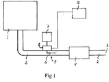
- the system 10 further comprises a comparator 12 adapted to comparing an actual value V1 and a set-point value V2 of a variable which is related to the function of the catalyst and is affected by the reducing agent injection, and to generating a signal S1 which represents the match between that actual value V1 and that set-point value V2.
- the calculation means 11 is adapted to determining said actual value V1 and set-point value V2 on the basis of information from the aforesaid computation model and, and the comparator 12 is therefore in this case adapted to receiving information from the calculation means 11 about the prevailing actual value V1 and set-point value V2.
- the comparator 12 is adapted to comparing the actual value V1 and the set-point value V2 and to delivering a signal S1 which depends on the match, e.g. the difference, between that actual value V1 and set-point value V2.
- the system 10 comprises also a regulator 13 adapted to generating, on the basis of said signal S1 from the comparator 12, a control signal v which acts upon the injection of reducing agent.
- the regulator 13 takes with advantage the form of a PI regulator but might alternatively take the form of an Otto Smith regulator.
- the regulator 13 is adapted to delivering the control signal v to an electronic control means 14 connected to the dosing unit 8 of the injection device and adapted to controlling this dosing unit on the basis of said control signal v so that an amount of reducing agent appropriate to prevailing conditions is injected into the exhaust line 2.
- the regulator 13 takes the form of a PI regulator, and the regulating parameters which in this case are determined by the calculation means 11 on the basis of the respective values of said amplification factor F and time constant ⁇ are the PI regulator's P amplification K p and I amplification K l .
- the calculation means 11, the comparator 12, the regulator 13 and the control means 14 are with advantage integrated in a common computer unit which may, if considered advantageous, be implemented in the form of two or more separate units connected to one another.
- the solution according to the invention might also be applied to regulation in the form of so-called cascade regulation, e.g. of the type described in EP 1 706 607 A1 , with an inner regulating circuit comprising a first regulator and an outer regulating circuit comprising a second regulator.
- cascade regulation e.g. of the type described in EP 1 706 607 A1
- regulating parameters of both of the regulators may be determined in the manner described above.
- Fig. 4 is a flowchart illustrating an embodiment of a method according to the present invention for determination of regulating parameters of a regulator 13 which forms part of a system for controlling the injection of reducing agent upstream of a catalyst 4 in an exhaust line 2 from a combustion engine 1, e.g. of a motor vehicle, and which, on the basis of a signal S1 which is delivered by a comparator 12 and depends on the match between an actual value V1 and a set-point value V2 of a variable related to the function of the catalyst and affected by the reducing agent injection, generates a control signal v which acts upon the injection of reducing agent.
- a control signal v which acts upon the injection of reducing agent.
- a first step A determines instantaneous values of said amplification factor F and said time constant ⁇ on the basis of information from a computation model which, while catering for the expected reactions in the catalyst 4 in the respective operating conditions, continuously determines current states in the catalyst, e.g. the accumulation in various parts of the catalyst of a reductive substance which forms part of, or is formed by, the reducing agent, and the conversion of exhaust substance which takes place in various parts of the catalyst under the influence of the reductive substance.
- a subsequent step B determines instantaneous values of regulating parameters of the regulator 13 on the basis of the thus determined values of said amplification factor F and time constant ⁇ . The aforesaid steps A and B are performed repetitively.
- Computer programme code for implementing a method according to the invention is with advantage included in a computer programme which can be read into the internal memory of computer, e.g. the internal memory of an electronic control unit of a motor vehicle.
- a computer programme is with advantage provided via a computer programme product comprising a data storage medium which is readable by an electronic control unit and which has the computer programme stored on it.
- Said data storage medium is for example an optical data storage medium in the form of a CD ROM disc, a DVD disc etc., a magnetic data storage medium in the form of a hard disc, a diskette, a cassette tape etc., or a flash memory or a memory of the ROM, PROM, EPROM or EEPROM type.
- a computer programme according to an embodiment of the invention comprises computer programme code for causing the calculation means 11 of a system 10 of the type described above to
- Fig. 3 illustrates very schematically an electronic control unit 20 comprising an execution means 21, e.g. a central processor unit (CPU), for execution of computer software.
- the execution means 21 communicates with a memory 23, e.g. of the RAM type, via a data bus 22.
- the control unit 20 comprises also data storage medium 24, e.g. in the form of a flash memory or a memory of the ROM, PROM, EPROM or EEPROM type.
- the execution means 21 communicates with the data storage medium 24 via the data bus 22.
- a computer programme comprising computer programme code for implementing a method according to the invention, e.g. in accordance with the embodiment illustrated in Fig. 4 , is stored on the data storage medium 24.
- the computation model may also use as input values the O 2 concentration in the exhaust gases upstream of the SCR catalyst and/or the ambient temperature.
- the O 2 concentration may be determined by means of, for example, lambda sensors but is with advantage determined in any of the conventional ways for calculating it, e.g. on the basis of the combustion engine's load, speed and, where applicable, EGR content.
- nitrogen oxide NO x reacts with ammonia and is reduced to nitrogen gas.
- No x is the harmful exhaust substance intended to be removed from the exhaust gases, and ammonia is the reductive substance used for the purpose.
- Ammonia or urea (the latter converts to ammonia) is injected into the exhaust gases upstream of the SCR catalyst.
- the method uses information from a catalyst model to determine the static and dynamic response to a change in the dosage of reducing agent (urea).
- the method therefore comprises two elements: a static and a dynamic element.
- the description is based on the catalyst model being formulated as a tank series model in which the active material in the respective tanks is divided into layers.
- the catalyst model comprises the following reactions: Urea + H 2 O ⁇ 2NH 3 + CO 2 (1) S + NH 3 ⁇ S -NH 3 (2) S-NH 3 ⁇ S + NH 3 (3) 4S-NH 3 + 4NO + O 2 ⁇ 4S + 6H 2 O + 4N 2 (4) 4S-NH 3 + 5O 2 ⁇ 4S + 6H 2 O + 4NO (5)
- the model comprises urea decomposition (reaction (1)) from dosage point to the catalyst.
- the model applies the simplification of regarding the isocyanic acid (HNCO) formed by decomposition of urea as equivalent to ammonia.
- HNCO isocyanic acid
- the total pressure P k may be added to the pressure after the catalyst, which is equal to atmospheric pressure if the catalyst is positioned last in the exhaust system. For a more accurate value, the pressure drop from the respective tank to the end of the catalyst is calculated from formulae for lamina flow in a channel and is added to the pressure after the catalyst. If the catalyst is not last in the system, the pressure may be measured or calculated from pressure drops across the unit or units situated after the catalyst.
- the material balances for the gas flow and for the gas phase in the active layers constitute an equation system from which mole fractions for the various substances in the gas flow and in the gas phase in the active layers are determined.
- the degree of coverage at each time is thereafter integrated on the basis of the time derivative.
- the temperature of the gas flow through the catalyst is determined by solving a heat balance which takes into account the heat transferred to the solid material and the reaction heat for homogeneous reactions.
- T g , k F tot ⁇ c p , g ⁇ T g , k ⁇ 1 + h k ⁇ A ch , h ⁇ T s , k + Q h , k F tot ⁇ c p , g + h k ⁇ A ch , k
- the temperature at each time is thereafter integrated on the basis of the time derivative.
- the static response is determined by static material balances for the gas flow and for the gas phase in the outermost layer.
- the effectiveness factor for internal mass transport depends primarily on temperature and may therefore be determined beforehand and set out in chart form or equation form as a function of temperature.
- a simplification used is the approximation of regarding the effectiveness factor for external mass transport as the same for NO x and for ammonia: ⁇ k ⁇ ⁇ N O x , k ⁇ ⁇ N H 3 , k
- the effectiveness factor for external mass transport may be determined from current mole fractions for NO x or from equilibrium mole fractions when determining the dynamic response below.
- the continued derivation of static response involves using only mole fractions for the gas flow, so the index n is supposed to be zero and is omitted.
- the product of the mole fraction in the gas flow and the effectiveness factor for external transport is used.
- the stoichiometric ratio between dosed urea and NO x in the exhaust gases before the catalyst is a relevant magnitude for the dosage.
- a stoichiometric ratio of one (1) means that the same amount of urea is dosed as would theoretically be used for reducing all of the NO x .
- This partial derivative describes the relationship between a change in the stoichiometry and the degree of coverage in tank k provided that no changes take place in the intermediate tanks 1 to k-1.
- the static response is reflected by the relationship between a change in the stoichiometry and the degree of coverage in tank k, taking changes in intermediate tanks into account.
- Determining the dynamic response involves first determining the equilibrium degree of coverage towards which the catalyst is heading with current dosage. This is followed by determining the rate at which the degree of coverage changes. The time constant is determined finally from the change from current degree of coverage to equilibrium degree of coverage and the rate of change. As the dynamics are quickest for the outermost layer, the layers within the outermost layer are regarded as static and the equilibrium degree of coverage for the outermost layer is determined on that basis.
- ⁇ eq , k A k ⁇ y s , eq , k A k ⁇ y s , eq , k + k d , k + B k ⁇ y s , N O x , k
- the following material balance for the outermost layer may be set up: ⁇ N H 3 , k , 0 ⁇ F ⁇ y f , eq , k + ⁇ N H 3 , k , 0 ⁇ y s , eq , k F + ⁇ N H 3 , k , 0 ⁇ y s , eq , k ⁇ ⁇ N H 3 , k , 1 ⁇ y s , eq , k ⁇ y N H 3 , k , 2 ⁇ A k ⁇ y s , eq , k ⁇ B k ⁇ y s , N O x , k ⁇ w k , 1 A k ⁇ y s , eq , k + k d , k + B k ⁇ y s , N O x , k ⁇ w k , 1 A
- the equilibrium degree of coverage is then arrived at by placing the equilibrium mole fraction in the equation for the equilibrium degree of coverage.
- the parameter ⁇ describes the factor multiplied by the time constant which describes the time needed for the whole build-up process of a step response.
- the time constant which describes the time needed for the whole build-up process of a step response.
- four time constants are needed for 99% of the change to be achieved.
- the parameter ⁇ needs also to make clear the deviation from the first order.
- a suitable value of ⁇ which gives a good match at the beginning of the response is of the order of 0.5 to 1.
- the aforesaid amplification factor F may be set to correspond to d x tot , N O x d v which is given by formula (52) above, and the aforesaid time constant ⁇ may be set to correspond to ⁇ tot , which is given by formula (69) above.
- the calculation method set out above may be modified in many different ways and it is also possible to use some other type of calculation method than that set out above for calculating the aforesaid amplification factor F and time constant ⁇ .
- a change which may be made is to use only one layer of active material, in which case the same derivation as above may be used by setting transport terms between the first and second layers to zero and setting the effectiveness factor for internal mass transport to one.
- Another change which may be made is to add reactions for NO 2 in order to be able to cater for a possible oxidation catalyst upstream of the SCR catalyst.
- the exhaust system may for example comprise at least one catalyst connected in series with the reduction catalyst 4, e.g. an oxidation catalyst and/or a hydrolysis catalyst upstream of the reduction catalyst and/or a slip catalyst downstream of the reduction catalyst.
- the exhaust system may also comprise a particle filter connected in series with the reduction catalyst 4 upstream or downstream of the latter.
Landscapes
- Engineering & Computer Science (AREA)
- Chemical & Material Sciences (AREA)
- Chemical Kinetics & Catalysis (AREA)
- Combustion & Propulsion (AREA)
- Mechanical Engineering (AREA)
- General Engineering & Computer Science (AREA)
- Health & Medical Sciences (AREA)
- Toxicology (AREA)
- Exhaust Gas After Treatment (AREA)
- Exhaust Gas Treatment By Means Of Catalyst (AREA)
Claims (14)
- Verfahren zur Bestimmung der Regelparameter eines Reglers (13), der Bestandteil eines Systems (10) zum Steuern der Einspritzung eines Reduktionsmittels stromaufwärts eines Katalysators (4) in einer von einem Verbrennungsmotor (1) abgehenden Abgasleitung (2) bildet, und der auf Basis eines Signals (S1), das von einem Komparator (12) geliefert wird und von der Übereinstimmung zwischen einem tatsächlichen Wert (V1) und einem Sollwert (V2) einer Variablen abhängt, die mit der Funktion des Katalysators in Beziehung steht und durch die Einspritzung des Reduktionsmittels betroffen ist, und der ein Steuersignal (v) erzeugt, das eine Wirkung auf die Einspritzung des Reduktionsmittels ausübt,
gekennzeichnet- durch den Einfluss der Reduktionsmitteleinspritzung auf die Variable, die als ein Prozess erster Ordnung mit einem Verstärkungsfaktor (F) und einer Zeitkonstante (τ) angenähert wird, wozu Momentanwerte dieses Verstärkungsfaktors und dieser Zeitkonstante auf Basis von Informationen von einem Rechenmodell bestimmt werden, das, während die erwarteten Reaktionen im Katalysator bei den jeweiligen Betriebsbedingungen berücksichtigt werden, die jeweiligen Zustände im Katalysator laufend bestimmt, z. B. die Ansammlung einer reduktiven Substanz in verschiedenen Teilen des Katalysators, die Teil des Reduktionsmittels ist oder von diesem gebildet wird, und die Umwandlung der im Abgas enthaltenen Substanzen, die in verschiedenen Teilen des Katalysators unter dem Einfluss der reduktiven Substanz stattfindet,und- durch Momentanwerte der Regelparameter, die auf Basis der so bestimmten Werte des Verstärkungsfaktors (F) und der Zeitkonstante (τ) bestimmt werden. - Verfahren nach Anspruch 1, dadurch gekennzeichnet, dass der Regler (13) ein PI-Regler ist und die Regelparameter die P-Verstärkung (Kp) und die I-Verstärkung (KI) des PI-Reglers sind.
- Verfahren nach Anspruch 1, dadurch gekennzeichnet, dass der Regler (13) ein Otto-Smith-Regler ist.
- Verfahren nach einem der Ansprüche 1 bis 3, wobei der Katalysator (4) ein SCR-Katalysator ist und Harnstoff oder Ammoniak als Reduktionsmittel verwendet wird, dadurch gekennzeichnet, dass die Variable der Ammoniak-Bedeckungsgrad im Katalysator (4) oder in einem Teil davon ist.
- Verfahren nach einem der Ansprüche 1 bis 3, wobei der Katalysator (4) ein SCR-Katalysator ist und Harnstoff oder Ammoniak als Reduktionsmittel verwendet wird, dadurch gekennzeichnet, dass die Variable der Grad der Umwandlung von NOx im Katalysator (4) ist.
- Verfahren nach einem der Ansprüche 1 bis 5, dadurch gekennzeichnet, dass mindestens die folgenden Eingangswerte im Rechenmodel bei der Erzeugung von Informationen zur Bestimmung des Verstärkungsfaktors (F) und der Zeitkonstante (τ) verwendet werden:- die Abgastemperatur (P1) stromaufwärts des Katalysators,- die NOx-Konzentration (P2) in den Abgasen stromaufwärts des Katalysators,- der Abgas-Massendurchsatz (P3) durch den Katalysator, und- eingespritzte Mengen (P4) des Reduktionsmittels.
- System zum Steuern der Einspritzung eines Reduktionsmittels stromaufwärts eines Katalysators in einer von einem Verbrennungsmotor abgehenden Abgasleitung, wobei das System (10) aufweist- einen Komparator (12), der zum Vergleichen eines tatsächlichen Wertes (V1) mit einem Sollwert (V2) einer Variablen eingerichtet ist, die mit der Funktion des Katalysators in Beziehung steht und durch die Einspritzung des Reduktionsmittels betroffen ist, und zum Erzeugen eines Signals (S1), das die Übereinstimmung zwischen dem tatsächlichen Wert (V1) und dem Sollwert (V2) repräsentiert,- einen Regler (13), der zum Erzeugen eines Steuersignals (v) auf Basis des Signals (S1) vom Komparator (12) eingerichtet ist, das auf die Reduktionsmitteleinspritzung eine Wirkung ausübt, und- ein elektronisches Berechnungsmittel (11), das ein Rechenmodell verwendet, um kontinuierlich aktuelle Zustände im Katalysator zu bestimmen, wobei die erwarteten Reaktionen im Katalysator bei den vorherrschenden Betriebsbedingungen berücksichtigt werden,dadurch gekennzeichnet, dass das Rechenmodell eingerichtet ist zum- Annähern des Einflusses der Reduktionsmitteleinspritzung auf die Variable als ein Prozess erster Ordnung mit einem Verstärkungsfaktor (F) und einer Zeitkonstante (τ),- Bestimmen von Momentanwerten dieses Verstärkungsfaktors (F) und dieser Zeitkonstante (τ) auf Basis der vom Rechenmodell erhaltenen Informationen, und- Bestimmen von Momentanwerten der Regelparameter des Reglers (13) auf Basis der so bestimmten Werte des Verstärkungsfaktors (F) und der Zeitkonstante (τ).
- System nach Anspruch 7, dadurch gekennzeichnet, dass der Regler (13) ein PI-Regler ist und die Regelparameter die P-Verstärkung (Kp) und die I-Verstärkung (KI) des PI-Reglers sind.
- System nach Anspruch 7, dadurch gekennzeichnet, dass der Regler (13) ein Otto-Smith-Regler ist.
- System nach einem der Ansprüche 7 bis 9, wobei der Katalysator ein SCR-Katalysator ist und Harnstoff oder Ammoniak als Reduktionsmittel verwendet wird, dadurch gekennzeichnet, dass die Variable der Ammoniak-Bedeckungsgrad im Katalysator (4) oder in einem Teil davon ist.
- System nach einem der Ansprüche 7 bis 9, wobei der Katalysator ein SCR-Katalysator ist und Harnstoff oder Ammoniak als Reduktionsmittel verwendet wird, dadurch gekennzeichnet, dass die Variable der Grad der Umwandlung von NOx im Katalysator (4) ist.
- Computerprogrammprodukt, das einen Computerprogrammcode aufweist, um ein zum Steuern der Einspritzung eines Reduktionsmittels stromaufwärts eines Katalysators in einer von einem Verbrennungsmotor abgehenden Abgasleitung konfiguriertes System zu veranlassen, und das aufweist▪ einen Komparator (12), der zum Vergleichen eines tatsächlichen Wertes (V1) mit einem Sollwert (V2) einer Variablen eingerichtet ist, die mit der Funktion des Katalysators in Beziehung steht und durch die Einspritzung des Reduktionsmittels betroffen ist, und zum Erzeugen eines Signals (S1), das die Übereinstimmung zwischen dem tatsächlichen Wert (V1) und dem Sollwert (V2) repräsentiert,▪ einen Regler (13), der zum Erzeugen eines Steuersignals (v) auf Basis des Signals (S1) vom Komparator (12) eingerichtet ist, das auf die Reduktionsmitteleinspritzung eine Wirkung ausübt, und▪ ein elektronisches Berechnungsmittel (11), das ein Rechenmodell verwendet, um kontinuierlich aktuelle Zustände im Katalysator zu bestimmen, wobei die erwarteten Reaktionen im Katalysator bei den jeweiligen Betriebsbedingungen berücksichtigt werden, dadurch gekennzeichnet, dass das Rechenmodell veranlasst wird,- den Einfluss der Reduktionsmitteleinspritzung auf die Variable als einen Prozess erster Ordnung mit einem Verstärkungsfaktor (F) und einer Zeitkonstante (τ) anzunähern,- Momentanwerte dieses Verstärkungsfaktors (F) und dieser Zeitkonstante (τ) auf Basis der vom Rechenmodell erhaltenen Informationen zu bestimmen, und- Momentanwerte der Regelparameter des Reglers (13) auf Basis der so bestimmten Werte des Verstärkungsfaktors (F) und der Zeitkonstante (τ) zu bestimmen.
- Computerprogrammprodukt nach Anspruch 12, dadurch gekennzeichnet, dass das Computerprogrammprodukt ein Datenspeichermedium aufweist, das von einer elektronischen Steuereinheit gelesen werden kann, wobei der Computerprogrammcode auf dem Datenspeichermedium gespeichert ist.
- Elektronische Steuereinheit für ein Kraftfahrzeug, die ein Ausführungsmittel (21), einen mit dem Ausführungsmittel verbundenen Speicher (23) und ein mit dem Ausführungsmittel verbundenes Datenspeichermedium (24) aufweist, wobei der Computerprogrammcode eines der Computerprogrammprodukts nach Anspruch 12 auf dem Datenspeichermedium (24) gespeichert ist.
Applications Claiming Priority (2)
| Application Number | Priority Date | Filing Date | Title |
|---|---|---|---|
| SE0900586A SE533728C2 (sv) | 2009-04-30 | 2009-04-30 | System för styrning av insprutningen av reduktionsmedel och förfarande för fastställande av reglerparametrar hos en regulator ingående i ett sådant system |
| PCT/SE2010/050467 WO2010126439A1 (en) | 2009-04-30 | 2010-04-28 | System for control of the injection of reducing agent and method for determination of regulating parameters of a regulator which forms part of such a system |
Publications (3)
| Publication Number | Publication Date |
|---|---|
| EP2425106A1 EP2425106A1 (de) | 2012-03-07 |
| EP2425106A4 EP2425106A4 (de) | 2017-03-22 |
| EP2425106B1 true EP2425106B1 (de) | 2018-03-14 |
Family
ID=43032397
Family Applications (1)
| Application Number | Title | Priority Date | Filing Date |
|---|---|---|---|
| EP10770031.2A Active EP2425106B1 (de) | 2009-04-30 | 2010-04-28 | System zur steuerung der injektion eines reduktionsmittels und verfahren zur bestimmung der regelparameter eines reglers eines derartigen systems |
Country Status (3)
| Country | Link |
|---|---|
| EP (1) | EP2425106B1 (de) |
| SE (1) | SE533728C2 (de) |
| WO (1) | WO2010126439A1 (de) |
Family Cites Families (6)
| Publication number | Priority date | Publication date | Assignee | Title |
|---|---|---|---|---|
| SE526404C2 (sv) * | 2004-01-20 | 2005-09-06 | Scania Cv Abp | Förfarande och anordning för styrning av insprutning av reduktionsmedel |
| DE102004031624A1 (de) * | 2004-06-30 | 2006-02-02 | Robert Bosch Gmbh | Verfahren zum Betreiben eines zur Reinigung des Abgases einer Brennkraftmaschine verwendeten Katalysators und Vorrichtung zur Durchführung des Verfahrens |
| US7784272B2 (en) * | 2004-08-31 | 2010-08-31 | Cummins Inc. | Control system for an engine aftertreatment system |
| JP2006125247A (ja) * | 2004-10-27 | 2006-05-18 | Hitachi Ltd | エンジンの排気ガス浄化方法及び排気ガス浄化装置 |
| GB0614445D0 (en) * | 2006-07-20 | 2006-08-30 | Ricardo Uk Ltd | Control of selective catalytic reduction |
| DE112007003583A5 (de) * | 2007-09-18 | 2010-07-29 | Fev Motorentechnik Gmbh | NH3-Überwachung eines SCR-Katalysators |
-
2009
- 2009-04-30 SE SE0900586A patent/SE533728C2/sv not_active IP Right Cessation
-
2010
- 2010-04-28 WO PCT/SE2010/050467 patent/WO2010126439A1/en not_active Ceased
- 2010-04-28 EP EP10770031.2A patent/EP2425106B1/de active Active
Non-Patent Citations (1)
| Title |
|---|
| None * |
Also Published As
| Publication number | Publication date |
|---|---|
| WO2010126439A1 (en) | 2010-11-04 |
| EP2425106A1 (de) | 2012-03-07 |
| EP2425106A4 (de) | 2017-03-22 |
| SE0900586A1 (sv) | 2010-10-31 |
| SE533728C2 (sv) | 2010-12-14 |
Similar Documents
| Publication | Publication Date | Title |
|---|---|---|
| EP1706607B1 (de) | Verfahren und vorrichtung zur steuerung der einspritzung eines reduktionsmittels | |
| CN101907012B (zh) | 调整还原剂计量添加量进行选择性催化还原的方法 | |
| EP1672192B1 (de) | Verfahren zur Regelung der Zugabe eines Reduktionsmittels in das Abgas einer Brennkraftmaschine | |
| JP5165500B2 (ja) | 選択的触媒還元制御システム及び方法 | |
| US8631786B2 (en) | Method, systems and sensor for detecting humidity | |
| CN101285414B (zh) | 还原剂喷射控制策略 | |
| EP2047088B1 (de) | Steuerung von selektiver katalytischer reduktion | |
| EP2181756B1 (de) | Verfahren zum Steuern eines SCR-Katalysators | |
| EP3551858B1 (de) | Verfahren und system zur steuerung eines ammoniakabdeckungsgradprofils | |
| US20070010020A1 (en) | Method and device for monitoring of a catalyst | |
| US20100050614A1 (en) | System and method for selective catalytic reduction control | |
| US8061122B2 (en) | Device for removing nitrogen oxides from internal combustion engine waste gas and method for dosing an aggregate of internal combustion engine waste gas | |
| EP2529093B1 (de) | Messung von stickoxiden und ammoniak | |
| US20140056788A1 (en) | Method for the model-based feedback control of an scr system having at least one scr catalytic converter | |
| KR102660647B1 (ko) | 모델링된 암모니아 충전 수준의 보정 방법 | |
| Hsieh | Control of diesel engine urea selective catalytic reduction systems | |
| CN107975407B (zh) | 用于调节内燃机发动机的排气后处理装置的方法 | |
| US20250163864A1 (en) | Apparatus and method for lambda control of spark-ignition engines, and motor vehicle | |
| CN1492965A (zh) | 废气再处理系统的控制方法和装置 | |
| EP2435674B1 (de) | Verfahren und system zur steuerung der injektion eines reduktionsmittels stromauf eines scr-katalysators | |
| SE1050084A1 (sv) | Skattning av en avvikelse för åtminstone en modellvariabel hos en katalysatormodell | |
| CN101002007A (zh) | 排气净化装置的控制方法 | |
| US20070056267A1 (en) | Method for operating an internal combustion engine and device for implementing the method | |
| CN102084095B (zh) | 颗粒过滤器温度调节的适应方法 | |
| WO2010126439A1 (en) | System for control of the injection of reducing agent and method for determination of regulating parameters of a regulator which forms part of such a system |
Legal Events
| Date | Code | Title | Description |
|---|---|---|---|
| PUAI | Public reference made under article 153(3) epc to a published international application that has entered the european phase |
Free format text: ORIGINAL CODE: 0009012 |
|
| 17P | Request for examination filed |
Effective date: 20111130 |
|
| AK | Designated contracting states |
Kind code of ref document: A1 Designated state(s): AT BE BG CH CY CZ DE DK EE ES FI FR GB GR HR HU IE IS IT LI LT LU LV MC MK MT NL NO PL PT RO SE SI SK SM TR |
|
| DAX | Request for extension of the european patent (deleted) | ||
| RA4 | Supplementary search report drawn up and despatched (corrected) |
Effective date: 20170216 |
|
| RIC1 | Information provided on ipc code assigned before grant |
Ipc: F02D 41/24 20060101ALI20170210BHEP Ipc: F01N 3/20 20060101AFI20170210BHEP Ipc: F01N 9/00 20060101ALI20170210BHEP Ipc: F02D 41/14 20060101ALN20170210BHEP |
|
| RIC1 | Information provided on ipc code assigned before grant |
Ipc: F01N 9/00 20060101ALI20170913BHEP Ipc: F02D 41/14 20060101ALN20170913BHEP Ipc: F01N 3/20 20060101AFI20170913BHEP Ipc: F02D 41/24 20060101ALI20170913BHEP |
|
| GRAP | Despatch of communication of intention to grant a patent |
Free format text: ORIGINAL CODE: EPIDOSNIGR1 |
|
| INTG | Intention to grant announced |
Effective date: 20171024 |
|
| GRAS | Grant fee paid |
Free format text: ORIGINAL CODE: EPIDOSNIGR3 |
|
| GRAA | (expected) grant |
Free format text: ORIGINAL CODE: 0009210 |
|
| AK | Designated contracting states |
Kind code of ref document: B1 Designated state(s): AT BE BG CH CY CZ DE DK EE ES FI FR GB GR HR HU IE IS IT LI LT LU LV MC MK MT NL NO PL PT RO SE SI SK SM TR |
|
| REG | Reference to a national code |
Ref country code: GB Ref legal event code: FG4D |
|
| REG | Reference to a national code |
Ref country code: CH Ref legal event code: EP Ref country code: AT Ref legal event code: REF Ref document number: 979102 Country of ref document: AT Kind code of ref document: T Effective date: 20180315 |
|
| REG | Reference to a national code |
Ref country code: IE Ref legal event code: FG4D |
|
| REG | Reference to a national code |
Ref country code: DE Ref legal event code: R096 Ref document number: 602010049184 Country of ref document: DE |
|
| REG | Reference to a national code |
Ref country code: FR Ref legal event code: PLFP Year of fee payment: 9 |
|
| REG | Reference to a national code |
Ref country code: NL Ref legal event code: MP Effective date: 20180314 |
|
| REG | Reference to a national code |
Ref country code: LT Ref legal event code: MG4D |
|
| PG25 | Lapsed in a contracting state [announced via postgrant information from national office to epo] |
Ref country code: FI Free format text: LAPSE BECAUSE OF FAILURE TO SUBMIT A TRANSLATION OF THE DESCRIPTION OR TO PAY THE FEE WITHIN THE PRESCRIBED TIME-LIMIT Effective date: 20180314 Ref country code: NO Free format text: LAPSE BECAUSE OF FAILURE TO SUBMIT A TRANSLATION OF THE DESCRIPTION OR TO PAY THE FEE WITHIN THE PRESCRIBED TIME-LIMIT Effective date: 20180614 Ref country code: HR Free format text: LAPSE BECAUSE OF FAILURE TO SUBMIT A TRANSLATION OF THE DESCRIPTION OR TO PAY THE FEE WITHIN THE PRESCRIBED TIME-LIMIT Effective date: 20180314 Ref country code: LT Free format text: LAPSE BECAUSE OF FAILURE TO SUBMIT A TRANSLATION OF THE DESCRIPTION OR TO PAY THE FEE WITHIN THE PRESCRIBED TIME-LIMIT Effective date: 20180314 Ref country code: ES Free format text: LAPSE BECAUSE OF FAILURE TO SUBMIT A TRANSLATION OF THE DESCRIPTION OR TO PAY THE FEE WITHIN THE PRESCRIBED TIME-LIMIT Effective date: 20180314 Ref country code: CY Free format text: LAPSE BECAUSE OF FAILURE TO SUBMIT A TRANSLATION OF THE DESCRIPTION OR TO PAY THE FEE WITHIN THE PRESCRIBED TIME-LIMIT Effective date: 20180314 |
|
| REG | Reference to a national code |
Ref country code: AT Ref legal event code: MK05 Ref document number: 979102 Country of ref document: AT Kind code of ref document: T Effective date: 20180314 |
|
| PG25 | Lapsed in a contracting state [announced via postgrant information from national office to epo] |
Ref country code: BG Free format text: LAPSE BECAUSE OF FAILURE TO SUBMIT A TRANSLATION OF THE DESCRIPTION OR TO PAY THE FEE WITHIN THE PRESCRIBED TIME-LIMIT Effective date: 20180614 Ref country code: GR Free format text: LAPSE BECAUSE OF FAILURE TO SUBMIT A TRANSLATION OF THE DESCRIPTION OR TO PAY THE FEE WITHIN THE PRESCRIBED TIME-LIMIT Effective date: 20180615 Ref country code: SE Free format text: LAPSE BECAUSE OF FAILURE TO SUBMIT A TRANSLATION OF THE DESCRIPTION OR TO PAY THE FEE WITHIN THE PRESCRIBED TIME-LIMIT Effective date: 20180314 Ref country code: LV Free format text: LAPSE BECAUSE OF FAILURE TO SUBMIT A TRANSLATION OF THE DESCRIPTION OR TO PAY THE FEE WITHIN THE PRESCRIBED TIME-LIMIT Effective date: 20180314 |
|
| PG25 | Lapsed in a contracting state [announced via postgrant information from national office to epo] |
Ref country code: EE Free format text: LAPSE BECAUSE OF FAILURE TO SUBMIT A TRANSLATION OF THE DESCRIPTION OR TO PAY THE FEE WITHIN THE PRESCRIBED TIME-LIMIT Effective date: 20180314 Ref country code: IT Free format text: LAPSE BECAUSE OF FAILURE TO SUBMIT A TRANSLATION OF THE DESCRIPTION OR TO PAY THE FEE WITHIN THE PRESCRIBED TIME-LIMIT Effective date: 20180314 Ref country code: RO Free format text: LAPSE BECAUSE OF FAILURE TO SUBMIT A TRANSLATION OF THE DESCRIPTION OR TO PAY THE FEE WITHIN THE PRESCRIBED TIME-LIMIT Effective date: 20180314 Ref country code: NL Free format text: LAPSE BECAUSE OF FAILURE TO SUBMIT A TRANSLATION OF THE DESCRIPTION OR TO PAY THE FEE WITHIN THE PRESCRIBED TIME-LIMIT Effective date: 20180314 Ref country code: PL Free format text: LAPSE BECAUSE OF FAILURE TO SUBMIT A TRANSLATION OF THE DESCRIPTION OR TO PAY THE FEE WITHIN THE PRESCRIBED TIME-LIMIT Effective date: 20180314 |
|
| PG25 | Lapsed in a contracting state [announced via postgrant information from national office to epo] |
Ref country code: CZ Free format text: LAPSE BECAUSE OF FAILURE TO SUBMIT A TRANSLATION OF THE DESCRIPTION OR TO PAY THE FEE WITHIN THE PRESCRIBED TIME-LIMIT Effective date: 20180314 Ref country code: SK Free format text: LAPSE BECAUSE OF FAILURE TO SUBMIT A TRANSLATION OF THE DESCRIPTION OR TO PAY THE FEE WITHIN THE PRESCRIBED TIME-LIMIT Effective date: 20180314 Ref country code: AT Free format text: LAPSE BECAUSE OF FAILURE TO SUBMIT A TRANSLATION OF THE DESCRIPTION OR TO PAY THE FEE WITHIN THE PRESCRIBED TIME-LIMIT Effective date: 20180314 Ref country code: SM Free format text: LAPSE BECAUSE OF FAILURE TO SUBMIT A TRANSLATION OF THE DESCRIPTION OR TO PAY THE FEE WITHIN THE PRESCRIBED TIME-LIMIT Effective date: 20180314 |
|
| REG | Reference to a national code |
Ref country code: CH Ref legal event code: PL |
|
| REG | Reference to a national code |
Ref country code: DE Ref legal event code: R097 Ref document number: 602010049184 Country of ref document: DE |
|
| REG | Reference to a national code |
Ref country code: BE Ref legal event code: MM Effective date: 20180430 |
|
| PG25 | Lapsed in a contracting state [announced via postgrant information from national office to epo] |
Ref country code: PT Free format text: LAPSE BECAUSE OF FAILURE TO SUBMIT A TRANSLATION OF THE DESCRIPTION OR TO PAY THE FEE WITHIN THE PRESCRIBED TIME-LIMIT Effective date: 20180716 |
|
| PLBE | No opposition filed within time limit |
Free format text: ORIGINAL CODE: 0009261 |
|
| STAA | Information on the status of an ep patent application or granted ep patent |
Free format text: STATUS: NO OPPOSITION FILED WITHIN TIME LIMIT |
|
| REG | Reference to a national code |
Ref country code: IE Ref legal event code: MM4A |
|
| PG25 | Lapsed in a contracting state [announced via postgrant information from national office to epo] |
Ref country code: DK Free format text: LAPSE BECAUSE OF FAILURE TO SUBMIT A TRANSLATION OF THE DESCRIPTION OR TO PAY THE FEE WITHIN THE PRESCRIBED TIME-LIMIT Effective date: 20180314 Ref country code: MC Free format text: LAPSE BECAUSE OF FAILURE TO SUBMIT A TRANSLATION OF THE DESCRIPTION OR TO PAY THE FEE WITHIN THE PRESCRIBED TIME-LIMIT Effective date: 20180314 Ref country code: LU Free format text: LAPSE BECAUSE OF NON-PAYMENT OF DUE FEES Effective date: 20180428 |
|
| 26N | No opposition filed |
Effective date: 20181217 |
|
| PG25 | Lapsed in a contracting state [announced via postgrant information from national office to epo] |
Ref country code: LI Free format text: LAPSE BECAUSE OF NON-PAYMENT OF DUE FEES Effective date: 20180430 Ref country code: BE Free format text: LAPSE BECAUSE OF NON-PAYMENT OF DUE FEES Effective date: 20180430 Ref country code: SI Free format text: LAPSE BECAUSE OF FAILURE TO SUBMIT A TRANSLATION OF THE DESCRIPTION OR TO PAY THE FEE WITHIN THE PRESCRIBED TIME-LIMIT Effective date: 20180314 Ref country code: CH Free format text: LAPSE BECAUSE OF NON-PAYMENT OF DUE FEES Effective date: 20180430 |
|
| PG25 | Lapsed in a contracting state [announced via postgrant information from national office to epo] |
Ref country code: IE Free format text: LAPSE BECAUSE OF NON-PAYMENT OF DUE FEES Effective date: 20180428 |
|
| PG25 | Lapsed in a contracting state [announced via postgrant information from national office to epo] |
Ref country code: MT Free format text: LAPSE BECAUSE OF NON-PAYMENT OF DUE FEES Effective date: 20180428 |
|
| PG25 | Lapsed in a contracting state [announced via postgrant information from national office to epo] |
Ref country code: TR Free format text: LAPSE BECAUSE OF FAILURE TO SUBMIT A TRANSLATION OF THE DESCRIPTION OR TO PAY THE FEE WITHIN THE PRESCRIBED TIME-LIMIT Effective date: 20180314 |
|
| PG25 | Lapsed in a contracting state [announced via postgrant information from national office to epo] |
Ref country code: HU Free format text: LAPSE BECAUSE OF FAILURE TO SUBMIT A TRANSLATION OF THE DESCRIPTION OR TO PAY THE FEE WITHIN THE PRESCRIBED TIME-LIMIT; INVALID AB INITIO Effective date: 20100428 |
|
| PG25 | Lapsed in a contracting state [announced via postgrant information from national office to epo] |
Ref country code: MK Free format text: LAPSE BECAUSE OF NON-PAYMENT OF DUE FEES Effective date: 20180314 |
|
| PGFP | Annual fee paid to national office [announced via postgrant information from national office to epo] |
Ref country code: FR Payment date: 20200312 Year of fee payment: 11 |
|
| PG25 | Lapsed in a contracting state [announced via postgrant information from national office to epo] |
Ref country code: IS Free format text: LAPSE BECAUSE OF FAILURE TO SUBMIT A TRANSLATION OF THE DESCRIPTION OR TO PAY THE FEE WITHIN THE PRESCRIBED TIME-LIMIT Effective date: 20180714 |
|
| PGFP | Annual fee paid to national office [announced via postgrant information from national office to epo] |
Ref country code: GB Payment date: 20200416 Year of fee payment: 11 |
|
| GBPC | Gb: european patent ceased through non-payment of renewal fee |
Effective date: 20210428 |
|
| PG25 | Lapsed in a contracting state [announced via postgrant information from national office to epo] |
Ref country code: GB Free format text: LAPSE BECAUSE OF NON-PAYMENT OF DUE FEES Effective date: 20210428 Ref country code: FR Free format text: LAPSE BECAUSE OF NON-PAYMENT OF DUE FEES Effective date: 20210430 |
|
| P01 | Opt-out of the competence of the unified patent court (upc) registered |
Effective date: 20230518 |
|
| PGFP | Annual fee paid to national office [announced via postgrant information from national office to epo] |
Ref country code: DE Payment date: 20250305 Year of fee payment: 16 |