EP2424080A1 - Driving motor - Google Patents
Driving motor Download PDFInfo
- Publication number
- EP2424080A1 EP2424080A1 EP10766798A EP10766798A EP2424080A1 EP 2424080 A1 EP2424080 A1 EP 2424080A1 EP 10766798 A EP10766798 A EP 10766798A EP 10766798 A EP10766798 A EP 10766798A EP 2424080 A1 EP2424080 A1 EP 2424080A1
- Authority
- EP
- European Patent Office
- Prior art keywords
- housing
- rotating shaft
- driving motor
- flange
- axial direction
- Prior art date
- Legal status (The legal status is an assumption and is not a legal conclusion. Google has not performed a legal analysis and makes no representation as to the accuracy of the status listed.)
- Withdrawn
Links
Images





Classifications
-
- F—MECHANICAL ENGINEERING; LIGHTING; HEATING; WEAPONS; BLASTING
- F04—POSITIVE - DISPLACEMENT MACHINES FOR LIQUIDS; PUMPS FOR LIQUIDS OR ELASTIC FLUIDS
- F04D—NON-POSITIVE-DISPLACEMENT PUMPS
- F04D25/00—Pumping installations or systems
- F04D25/02—Units comprising pumps and their driving means
- F04D25/08—Units comprising pumps and their driving means the working fluid being air, e.g. for ventilation
-
- F—MECHANICAL ENGINEERING; LIGHTING; HEATING; WEAPONS; BLASTING
- F04—POSITIVE - DISPLACEMENT MACHINES FOR LIQUIDS; PUMPS FOR LIQUIDS OR ELASTIC FLUIDS
- F04D—NON-POSITIVE-DISPLACEMENT PUMPS
- F04D25/00—Pumping installations or systems
- F04D25/02—Units comprising pumps and their driving means
- F04D25/06—Units comprising pumps and their driving means the pump being electrically driven
- F04D25/0606—Units comprising pumps and their driving means the pump being electrically driven the electric motor being specially adapted for integration in the pump
- F04D25/0613—Units comprising pumps and their driving means the pump being electrically driven the electric motor being specially adapted for integration in the pump the electric motor being of the inside-out type, i.e. the rotor is arranged radially outside a central stator
-
- F—MECHANICAL ENGINEERING; LIGHTING; HEATING; WEAPONS; BLASTING
- F04—POSITIVE - DISPLACEMENT MACHINES FOR LIQUIDS; PUMPS FOR LIQUIDS OR ELASTIC FLUIDS
- F04D—NON-POSITIVE-DISPLACEMENT PUMPS
- F04D25/00—Pumping installations or systems
- F04D25/02—Units comprising pumps and their driving means
- F04D25/06—Units comprising pumps and their driving means the pump being electrically driven
- F04D25/068—Mechanical details of the pump control unit
-
- F—MECHANICAL ENGINEERING; LIGHTING; HEATING; WEAPONS; BLASTING
- F04—POSITIVE - DISPLACEMENT MACHINES FOR LIQUIDS; PUMPS FOR LIQUIDS OR ELASTIC FLUIDS
- F04D—NON-POSITIVE-DISPLACEMENT PUMPS
- F04D29/00—Details, component parts, or accessories
- F04D29/66—Combating cavitation, whirls, noise, vibration or the like; Balancing
- F04D29/661—Combating cavitation, whirls, noise, vibration or the like; Balancing especially adapted for elastic fluid pumps
- F04D29/668—Combating cavitation, whirls, noise, vibration or the like; Balancing especially adapted for elastic fluid pumps damping or preventing mechanical vibrations
-
- H—ELECTRICITY
- H02—GENERATION; CONVERSION OR DISTRIBUTION OF ELECTRIC POWER
- H02K—DYNAMO-ELECTRIC MACHINES
- H02K11/00—Structural association of dynamo-electric machines with electric components or with devices for shielding, monitoring or protection
- H02K11/30—Structural association with control circuits or drive circuits
- H02K11/33—Drive circuits, e.g. power electronics
-
- H—ELECTRICITY
- H02—GENERATION; CONVERSION OR DISTRIBUTION OF ELECTRIC POWER
- H02K—DYNAMO-ELECTRIC MACHINES
- H02K5/00—Casings; Enclosures; Supports
- H02K5/04—Casings or enclosures characterised by the shape, form or construction thereof
-
- H—ELECTRICITY
- H02—GENERATION; CONVERSION OR DISTRIBUTION OF ELECTRIC POWER
- H02K—DYNAMO-ELECTRIC MACHINES
- H02K5/00—Casings; Enclosures; Supports
- H02K5/04—Casings or enclosures characterised by the shape, form or construction thereof
- H02K5/10—Casings or enclosures characterised by the shape, form or construction thereof with arrangements for protection from ingress, e.g. water or fingers
-
- H—ELECTRICITY
- H02—GENERATION; CONVERSION OR DISTRIBUTION OF ELECTRIC POWER
- H02K—DYNAMO-ELECTRIC MACHINES
- H02K5/00—Casings; Enclosures; Supports
- H02K5/04—Casings or enclosures characterised by the shape, form or construction thereof
- H02K5/18—Casings or enclosures characterised by the shape, form or construction thereof with ribs or fins for improving heat transfer
-
- H—ELECTRICITY
- H02—GENERATION; CONVERSION OR DISTRIBUTION OF ELECTRIC POWER
- H02K—DYNAMO-ELECTRIC MACHINES
- H02K5/00—Casings; Enclosures; Supports
- H02K5/04—Casings or enclosures characterised by the shape, form or construction thereof
- H02K5/20—Casings or enclosures characterised by the shape, form or construction thereof with channels or ducts for flow of cooling medium
- H02K5/207—Casings or enclosures characterised by the shape, form or construction thereof with channels or ducts for flow of cooling medium with openings in the casing specially adapted for ambient air
-
- H—ELECTRICITY
- H02—GENERATION; CONVERSION OR DISTRIBUTION OF ELECTRIC POWER
- H02K—DYNAMO-ELECTRIC MACHINES
- H02K5/00—Casings; Enclosures; Supports
- H02K5/04—Casings or enclosures characterised by the shape, form or construction thereof
- H02K5/22—Auxiliary parts of casings not covered by groups H02K5/06-H02K5/20, e.g. shaped to form connection boxes or terminal boxes
-
- H—ELECTRICITY
- H02—GENERATION; CONVERSION OR DISTRIBUTION OF ELECTRIC POWER
- H02K—DYNAMO-ELECTRIC MACHINES
- H02K5/00—Casings; Enclosures; Supports
- H02K5/24—Casings; Enclosures; Supports specially adapted for suppression or reduction of noise or vibrations
-
- H—ELECTRICITY
- H02—GENERATION; CONVERSION OR DISTRIBUTION OF ELECTRIC POWER
- H02K—DYNAMO-ELECTRIC MACHINES
- H02K7/00—Arrangements for handling mechanical energy structurally associated with dynamo-electric machines, e.g. structural association with mechanical driving motors or auxiliary dynamo-electric machines
- H02K7/14—Structural association with mechanical loads, e.g. with hand-held machine tools or fans
Definitions
- the present invention relates to a motor for driving a predetermined air-conditioning device such as a fan, where the motor being housed in a case with an air flow duct, such as a blower case of a blower unit, which may configure a vehicle air conditioner.
- a vehicle-mounted blower equipped with a brushless motor as mentioned in Patent Document 1 is already known.
- the vehicle-mounted blower disclosed in Patent Document 1 is provided with a brushless motor that rotates a blower fan, a cooling fin molded in a single body in a metallic housing of the brushless motor, an auxiliary blade arranged in the blower fan to produce an air flow around the cooling fin, and a driving element closely attached to the housing.
- the objective thereof is to increase the cooling capacity of the motor driving element and reduce the size in a height direction of the blower as well as to take measures to curtail the manufacturing cost by reducing the number of parts.
- Patent Document 2 there is known a motor configured such that an interior space is formed by a metallic casing extended in an umbrella shape that opens from a rotating shaft bellow both blade wheel boss part and cone part that extends from the boss part, and a non metallic (for example, resin made) bottom plate that can cover a lower opening of this casing, the armature is housed in the interior space, and the casing and the bottom plate are fixed tightly and closely by screwing outwardly extending two flanges formed at the circumferential edge.
- a brushless motor as disclosed in Patent Document 3, for example.
- the brushless motor is directed at the use for a compressor unit of a home use air-conditioner rather than the blower unit of the vehicle air conditioner, it has a structure to prevent water from entering the motor interior-space when this compressor unit of the air conditioner is sprayed with water.
- the brushless motor has a water-proof structure including a cylindrical casing.
- the cylindrical casing has a stator to be protected from water and is divided into left-right two cup-shaped casings at a vertical plane in the general center of the size of a rotating shaft direction.
- a protrusion is arranged on one surface of the cup-shaped casing and a groove is arranged on the other surface of the cup-shaped casing, the protrusion is inserted into the groove, and an O-shaped ring is provided between the groove and the protrusion, whereby the left-right cup-shaped casings are air-tightly joined.
- Patent Document 4 discloses a driving motor for a blower unit of a vehicle air conditioner having a structure wherein a rotor assembly is rotated by appropriately switching the magnetic power between a stator assembly and a rotor assembly, which are component parts of a magnetic circuit, and a rotating shaft is rotated along therewith.
- a rotating direction a radial direction of the rotating shaft
- a driving motor for a blower unit of a vehicle air conditioner is disclosed in Fig. 5 of Patent Document 4.
- the driving motor is structured such that a rotor member such as a multi-blade fan is attached to one side end along an shaft direction of a rotating shaft and the rotor member is rotated to take in air and blow air in a predetermine direction.
- a rotor member such as a multi-blade fan
- the rotor member is rotated to take in air and blow air in a predetermine direction.
- the rotor is rotatably supported in the stator and the lower end of the center piece of the stator is fixed in the motor holder through a vibration-proof material.
- the vibration-proof material is made of rubber having hardness from 20 to 40 in a generally cylindrical shape with a cylindrical through-hole in the central part.
- the inner diameter has the smallest size in the central region in the axial direction of the through-hole, and the inner diameter of the through-hole gradually expands towards the both openings.
- An annular groove is formed in the axial direction central region of the rubber cylinder outer surface.
- the brushless motor of the vehicle-mounted blower disclosed in Patent Document 1 is configured such that the lower case is arranged at the lower side of the upper case to form a chamber for installing a control circuit-board. Because the control circuit-board is stored in the this chamber, and the chamber has a convex portion bloated bellow the upper case, causes a problem that the vehicle-mounted blower has to be installed in the duct while the convex portion is protruding outside the duct.
- the brushless motor of the vehicle-mounted blower disclosed in Patent Document 1 has a problem that the structure becomes complex because the cooling fin which dissipates heat produced from the elements on the control circuit-board faces the blower fan side. As a result, the manufacturing cost of the brushless motor is also relatively high. Then, the brushless motor disclosed in Patent Document 1 has another problem that the component parts of the blushless motor is prone to rust due to insufficient water-proof measures, regardless of the blushless motor to be used in a vehicle-mounted blower.
- the brushless motor of the vehicle-mounted blower disclosed in Patent Document 2 is configured such that the lower case is arranged at the lower side of the upper case to form the control circuit-board chamber in which the control circuit-board is installed, so that there is the convex portion bloated bellow the upper case.
- this motor has a problem that the vehicle-mounted blower has to be arranged in the duct while the convex portion is protruding outside the duct.
- the brushless motor of the vehicle-mounted blower disclosed in Patent Document 2 has a problem that the structure becomes complex because the cooling fin which dissipated heat produced from the elements on the control circuit-board is facing the blower fan. As a result, the manufacturing cost of the brushless motor is also relatively high. Then, the brushless motor disclosed in Patent Document 2 has another problem that the component parts of the blushless motor are easily rusted due to insufficient water-proof measures regardless of the blushless motor being used in a vehicle-mounted blower.
- a first objective of the present invention is to meet a demand of making the length of a rotating shaft of the driving motor to be shorter in the axial direction.
- a second objective is to achieve a reduction in manufacturing cost and to ensure water-proof performance of a motor interior-space by inhibiting a vibration transmission to a flange by means of attenuating a transmission amount of a vibration component caused by rain water that flows in together with the wind.
- a third objective thereof is to reduce the noise generation and achieve an enhanced quietness by surely attenuating vibrations transmitted to the flange, absorbing a magnetic vibration through a sophisticated flange structure, and alleviating a resonant sound.
- the driving motor according to the present invention is a driving motor for transmitting a rotation force to a rotor member so as to rotate the rotor member
- a motor main body includes: a rotating shaft for rotating the rotor member which is attached to one end in an axial direction; a rotor assembly being attached to the rotating shaft and rotating together with the rotating shaft; a stator assembly facing to the rotor assembly in a radial direction of the rotating shaft and being arranged not rotating together with the rotating shaft; a control circuit-board that controls rotation of the rotating shaft as well as the rotor assembly; and a housing having a first opening which is formed in the relatively vicinity of the rotor member and a second opening relatively spaced apart from the rotor member, whereas the housing extends from around of the rotating shaft to outward in radial direction of the rotating shaft at the vicinity of one end, where it opens at the other end of the axial direction of the rotating shaft, and the housing at the other end of the axial direction of the rotating shaft is covered by a f
- One end in the axial direction of the rotating shaft is protruding outwardly toward the rotor member side from the housing, and the other end in the axial direction of the rotating shaft is contained in the motor interior-space (claim 2).
- aspects of the driving motor according to the invention include: a driving motor for a blower unit for a large volume of air, wherein the rotor assembly is also contained in the motor interior-space of the housing, the control circuit-board is arranged to be contained in the motor interior-space of the housing, being located in the vicinity of one end of the rotating shaft than the rotor assembly and the stator assembly in the axial direction of the rotating shaft, and a yoke is disposed to be contained in the motor interior-space of the housing, being located in the vicinity of the other end in the axial direction of the rotating shaft (claim 3); and a driving motor for a blower unit for a small volume of air, wherein the rotor assembly is also contained in the motor interior-space of the housing, the control circuit-board is arranged to be contained in the motor interior-space of the housing, being located in the vicinity of the other end of the rotating shaft than the rotor assembly and the stator assembly in the axial direction of the rotating shaft, a yoke is disposed to be
- the driving motor according to the present invention is characterized in that an elastic ring member is provided in a cylindrical gap between the first opening of the housing and the rotating shaft (claim 5). Therefore, the first opening of the housing and the rotating shaft are sealed, and therefore, there is no gap therebetween. As a result, it is possible to prevent water such as rain water from entering the motor interior-space through the gap between the first opening of the housing and the rotating shaft, and it is also possible to prevent the transmission of the rotation vibration from the rotating shaft to the housing because of the elasticity provided by the elastic ring member.
- the driving motor according to the present invention may be characterized in that the rotor member includes a cone part that has a boss part to which the rotating shaft is fixed, the cone part which has a boss part and a first cylindrical part, which is positioned in outer circumference of the rotating shaft than the boss part and extending in axial direction toward the opposite end of the rotating shaft, while the housing has a second cylindrical part which extends in the axial direction of the rotating shaft to the boss part of the cone part and its outer radius being smaller than an inner radial size of the first cylindrical part, and it also has a first opening in which the rotating shaft is to be inserted the circumferential part of the first opening being extending toward the rotating shaft so as to form a flange, with witch, at a time of assembling the driving motor and the rotor member, the second cylindrical part, being housed in the first cylindrical part generates a space in a relatively complex manner (claim 6). This eliminates a need for the provision of the elastic ring member, and thus, the number of parts of
- the driving motor according to the present invention is characterized in that the rotating shaft, the rotor assembly, and the stator assembly which are integrally formed as a vibrator, and the vibrator is fixed to the flange through a elastic mounting member (claim 7).
- the interposed elastic mounting member can attenuate the transmission amount of vibrations, and thus, it is possible to inhibit the transmission of the vibration components from the vibration source to the flange.
- the driving motor according to the present invention is characterized in that an elastic member is interposed between the housing and the flange at a time of covering the second opening side of the housing, the intervening elastic member to include three or more receiving parts each having a surface to interface the housing end surface which is opposing to the flange, wherein the receiving parts being arranged to surround the rotating shaft to support the motor main body (claim 8).
- the flange indirectly abuts the housing with the intervening elastic member in between.
- the motor main body is supported in the receiving part and a contact area between the housing and the flange is reduced, silent rotation of the driving motor to can be realized.
- the fact that the receiving parts are arranged at three locations or more to surround the rotating shaft makes the flange and the housing stably positioned, which can more effectively reduce precession.
- the intervening elastic member is configured such that a spring constant in a rotating direction of the rotating shaft is smaller than a spring constant in an axial direction of the rotating shaft (claim 10). That is because the spring constant in the rotating direction of the rotating shaft is a numerical value corresponding to a magnetic vibration.
- the spring constant in the axial direction of the rotating shaft is a numerical value corresponding to a precession.
- the driving motor according to the present invention may be characterized in that an elastic member is interposed between the housing and the flange at a time of covering the second opening side of the housing, the intervening elastic member to include a plurality of liner grooves in an area opposing to the second opening of the housing (claim 9).
- an elastic member is interposed between the housing and the flange at a time of covering the second opening side of the housing, the intervening elastic member to include a plurality of liner grooves in an area opposing to the second opening of the housing (claim 9).
- the driving motor according to the present invention is characterized in that the flange, at a time of covering the second opening side of the housing, the flange to includes a peripheral edge elastic member on its surface which is facing the second opening of the housing ,whereas the peripheral edge elastic member being compressed by a pressing force generated by the housing in roughly a radial direction of the rotating shaft, while at the same time the peripheral edge elastic member contacts a region near the second opening on an outer peripheral surface of the housing so that a compressing force does not work in the axial direction of the rotating shaft (claim 11).
- peripheral edge elastic members are arranged in radial outer area of the flange surface which is facing the second opening of the housing, so that the plastic member is pressed by the housing toward the radial external side of the rotating shaft to be in compressed state. Consequently, water such as rain water can not enter the motor interior-space from the gap between the peripheral edge elastic member and the housing, thus the peripheral edge elastic member provides water-proof effect. At the same time, there is no pressing force by the housing onto the surface in the axial direction, and thus, the peripheral edge elastic member is not compressed along the axial direction of the rotating shaft. As a result, it is possible to inhibit the transmission of the vibration component such as the magnetic vibration or the rotation vibration from the housing to the flange, and therefore, it is possible to provide a vibration attenuation effect by the peripheral edge elastic member.
- the driving motor according to the present invention may be configured such that a heat dissipation accelerator for enhancing dissipation of heat generated in the motor interior-space to outside the motor interior-space is arranged on a surface facing the rotor member (claim 12).
- a heat dissipation accelerator for enhancing dissipation of heat generated in the motor interior-space to outside the motor interior-space is arranged on a surface facing the rotor member (claim 12).
- the heat dissipation accelerator include a liner rib extending along the axial direction of the rotating shaft, a plurality of protrusions, and a plurality of recesses (dimples). These eliminate a need of providing a heat dissipation device such as a cooling fin and a heat sink.
- the driving motor according to the present invention may be configured such that a surface facing the second opening of the housing of the flange has a rib which consists of a plurality of liner protrusions extending toward the housing (claim 13).
- the rib further include one which consists of both a plurality of liner protrusions radially extending toward the outer edge side from the rotating shaft and a plurality of liner protrusions concentrically arranged at predetermined intervals, where the rotating shaft is a center point, another one which has a plurality liner protrusions are arranged in a honeycomb shape, and another which has a plurality of liner protrusions are arrange in a hexagonal shape.
- the rigidity of the flange is relatively improved by the rib, the conventionally generated resonant sound due to the magnetic vibration resulting from the deformation of the flange surface can be reduced, and the magnetic vibration can be absorbed by the vibration-proof elastic member.
- the metal housing that contains at least the stator assembly covers the stator assembly from above like an umbrella shape; it is possible to provide the stator assembly with a water-proof function.
- the housing which is made of metal of excellent thermal conductivity contains the stator assembly in it and the external surface of it is exposed to an air duct of a case such as a blower case, the heat from the stator assembly is transmitted to the housing, and the heat from the control circuit-board is also transmitted to the housing. Accordingly, the external surface of the housing faces the air duct of the case, heat generated from the stator assembly can be easily dissipation from the external surface of the housing. As a result, it is possible to promote a decrease of a temperature of the whose driving motor. This eliminates a need of a heat dissipation device such as a heat sink, and thus, the driving motor can be made compact and manufacturing cost of the motor can be reduced while keeping excellent heat dissipation.
- all the components arranged bellow the flange in the conventional driving motors are arranged upper side of the flange, and therefore, a need of a lower case attached at a lower portion of the flange in the conventional driving motors can be eliminated.
- the lower portion of the driving motor can be formed in a flat shape, and the size in the axial direction of the rotating shaft of the driving motor can be relatively made smaller by the thickness of the lower case of the conventional driving motors.
- control circuit-board is also contained in the housing, and thus, it is possible to provide the control circuit-board with a water-proof function, which enables an elimination of a particular need of preparing a control circuit-board mounting space for installing the control circuit-board.
- the heat from the control circuit-board is also transmitted to the housing, but the external surface of the housing is exposed to an air duct of the case, and thus, it is possible to dissipate the heat generated by the control circuit-board from the external surface of the housing. From this point, a need of a heat dissipation device such as a heat sink is eliminated.
- the elastic mounting member that is inserted in the first opening can attenuate the transmission amount of the vibration component, and therefore, it is possible to inhibit the transmission of the vibration component from the vibration source to the flange.
- a vibration absorption effect can be enhanced by the intervening elastic member, and thus, it is possible to achieve a further noise reduction of the driving motor.
- a peripheral edge elastic member is disposed in outer region in axial direction of the flange that is facing the second opening of the housing, and the inner surface in radial direction of the peripheral edge elastic member contacts the housing, the elastic member is pressed toward radial external direction and it is in compressed state. Therefore, the peripheral edge elastic member adheres closely to the outer peripheral surface of the housing, and water such as rain water does not enter the motor interior-space from the gap between the peripheral edge elastic member and the housing. As a result, it is possible to provide the peripheral edge elastic member with a water-proof effect.
- a vibration attenuation is enhanced by a vibration-proof elastic member, and thus, it is possible to achieve a further reduction of noise from the driving motor.
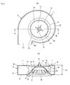
- a blower unit 1 shown in Fig. 1 is situated in downstream of a battery for cooling the battery (not shown) and is used to inhales the heated air from the battery and to dissipate outside.
- the blower unit 1 is designed for a small air volume, and includes a scroll-shaped blower case 2, a driving motor 3, and a multi-blade fan 4.
- the blower case 2 is made of resin or the like, and includes: an upper side wall 7 having an opening 6 where a bell mouth 5 is formed integrated or separately; a lower side wall 9 that is arranged to face the upper side wall 7 at a predetermined interval and having therein a motor insertion hole 8 into which the driving motor 3 is installed; and an outer peripheral wall 10 situated to connect outer peripheral edges of the upper side wall 7 and the lower side wall 9 while providing a exhausting outlet 11 between them.
- the outer peripheral wall 10 starts from a winding start portion 10a, and is formed in spiral shape so that a distance from the center of the multi-blade fan 4 to the wall gradually increases along a circumferential direction of the multi-blade fan 4.
- the multi-blade fan 4 itself is well known and, as shown in Figs. 1 , 2 , 4 and 5 , it includes: a boss part 13 fixed to a rotating shaft 12, described bellow, of the driving motor 3; a cone part 14 which is extending from the boss part 13; a plurality of blades 15 that are disposed in an upright position along the axial direction of the rotating shaft 12 and disposed along the circumferential direction of the outer peripheral edge of the cone part 14.
- the air flown in from an inlet 16 defined by the blades 15 and facing the cone part 14 is guided to the side of the blade 15 along the cone part 14 and passed through between the blade 15 and the blade 15.
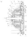
- a motor main body 23 includes: the rotating shaft 12; a boss housing 17; a stator assembly 18 attached on the outer peripheral surface of the boss housing 17; a control circuit-board 19; a rotor assembly 20; a housing 21; and a flange 22, as shown in Figs. 1 , 2 , 4 and 5 .
- the rotating shaft 12 is formed in a generally circular rod shape.
- the rotating shaft 12 enables rotation of a rotor member, such as a multi-blade fan 4, which are attached to the upper end in the longitudinal direction of the rotating shaft 12.
- the rotating shaft 12 is rotatably supported by bearings 24 and 25 which are mounted to the cylindrical boss housing 17 that is extending from the housing 21 downward in the axial direction of the rotating shaft 12.
- the bearings 24 and 25 are ball bearings, for example, and this allows the bearing 25 to prevent rain water entering inside together with wind from entering the motor interior-space 50 described below.
- stator assembly 18 is disposed on the outer peripheral surface of the boss housing 17, wherein the outer peripheral surface is extending downward in the axial direction of the rotating shaft 12.
- This stator assembly 18 consists of an iron core and an armature winding which are wound multiple times around the outer peripheral surface at the side of the core.
- the rotor assembly 20 is attached to the rotating shaft 12 at an upper position in the axial direction of the rotating shaft 12 above the stator assembly 18.
- This rotor assembly 20 faces the stator assembly 18 in the radial direction of the rotating shaft 12, and it consists of a yoke 26 and magnets 27 which are positioned on the inner side surface of the yoke 25 to face the armature winding of the stator assembly 18.
- the magnets 27 are made of sintered ferrite, for example.
- the driving motor 3 includes a relatively thin-plate control circuit-board 19, on which electronic parts to control switching of a current fed to the armature winding of the stator assembly 18 through an electronic switch or the like are disposed.
- the control circuit-board 19 includes a heat radiation part 29 such as a capacitor 28 and a transistor.
- the control circuit-board 29 is situated in the lower end in the axial direction of the rotating shaft 12 than the stator assembly 18 and the rotor assembly 20, and the heat radiation part 29 such as capacitors 28 and transistors are also situated at the bottom surface side of the control circuit-board 19.
- the housing 21 gradually increases its diameter from at around the rotating shaft 12 at the same time in the vicinity of the boss part 13 to the opposite end of the shaft 12 in the axial direction.
- the housing has opening at the opposite end of the boss part 13 to make an umbrella like structure as a whole, and it is cylindrical in that is has a first opening at the multi-blade fan 4 side and a second opening at the flange 22 side.
- the housing 21 is made of a material which has excellent thermal conductivity, for example, metal such as aluminum.
- the flange 22 can cover the second opening which is the other opening made at the opposite end of the housing close to the boss part 13, and it has a recessed part 30 at the central region which is facing housing 21 side.
- the recessed part 30 preferably may have enough volume to contain small electronic parts such as capacitors 28 and transistors, size in the axial direction of the rotating shaft 12 being equal to or less than 10 mm, for example.
- the flange 22 is made of a material, for example, resin such as polypropylene (PP) resin. Otherwise, the flange 22 could be made of a metal as the material.
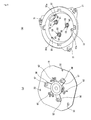
- the flange of the driving motor 3 shown in Figs. 2 and 4 as wall as shown in Fig. 6(b) , has a concave part 31, at the peripheral edge that can meet at least the peripheral collar part 21 a of the housing 21 is formed.
- a plurality of protrusions 32 are arranged on the bottom surface of the recessed part 30 of the flange 22, and an insertion part 32a is formed at the top of the protrusion 32, as shown in Fig. 6(b) .
- the insertion part 32a of the protrusion 34 can be inserted into an insertion hole 33 formed in the back surface of the control circuit-board 18 shown in Fig. 6(a) , accordingly, as shown in Figs. 2 and 4 , the insertion part 32a together with the protrusion 32 play a role of a stud to support the control circuit-board 19 from the flange 22 side.
- the recessed part 30 and the protrusion 32 are not shown because the position of the cross section of the driving motor 3 is different from the driving motor 3,for example shown in Figs. 2 and 4 .
- the driving motor 3 shown in Fig. 5 may also has the recessed part 30 like that shown in shown in Figs. 2 and 4 , where the protrusion 32 are configured to be inserted into the insertion hole 33 of the control circuit-board 19 so that the control circuit-board 19 is secured from the flange 22 side.
- a motor interior-space 35 is formed in the driving motor 3, as shown in Figs. 2 , 4 , and 5 .
- the motor interior-space 35 can hold the control circuit-board 19 and at least the end portion, the opposite side of the boss part 13, of the rotating shaft 12, and further holds the stator assembly 18 and the rotor assembly 20 in a space above the control circuit-board 19. Since the motor interior-space 35 has the recessed part 30 of the flange 22 to form a lower space below the control circuit-board 19, the heat radiation part 29 such as capacitors 28 and transistors are disposed.
- the driving motor 3 for a small volume of air, all the parts can be disposed above the flange 22 unlike in the conventional driving motors where parts are disposed bellow the flange 22, accordingly, a lower case attached bellow the flange 22 in the conventional driving motors is eliminated.
- the lower surface of the driving motor 3 is formed in an generally flat, and since the driving motor 3 does not stick to outside, the duct can be avoided even when the blower unit 1 is arranged in the duct, and the driving motor 3 can be improved in terms of layout when the blower unit 1 is mounted on a vehicle, etc.
- the size H1 (shown in Fig. 1(b) ) along the axial direction of the rotating shaft 12 of the driving motor 3 can be made relatively smaller by the thickness of the lower case of the conventional driving motors.
- the housing 21 of the driving motor 3 for a small air volume has its outer surface exposed to an air duct 36 of the blower unit 1, and further, the housing 21 is made of a material which has excellent thermal conductivity, for example a metal such as aluminum, as described above.
- a material which has excellent thermal conductivity for example a metal such as aluminum, as described above.
- This heat dissipation mechanism enables simple structure of the driving motor 3 without using a heat dissipation device such as a heat sink. At the same time, a manufacturing cost of the blower unit 1 can be relatively reduced due to the reduced number of parts, and the blower unit 1 can be further made smaller as well as the driving motor 3.
- a blower unit 1 shown in Fig. 7 is situated in downstream of a battery for cooling the battery (not shown) and is used to inhales the heated air from the battery and to dissipate outside.
- the blower unit 1 is designed for a large air volume, and includes a scroll-shaped blower case 2, a driving motor 3, and a multi-blade fan 4.
- the blower case 2 is made of resin or the like, and includes: an upper side wall 7 having an opening 6 where a bell mouth 5 is formed integrated or separated; a lower side wall 9 that is arranged to face the upper side wall 7 at a predetermined interval and having therein a motor insertion hole 8 into which the driving motor 3 is installed; and an outer peripheral wall 10 situated to connect outer peripheral edges of the upper side wall 7 and the lower side wall 9 while providing a exhausting outlet 11 between them.
- the outer peripheral wall 10 starts from a winding start portion 10a, and is formed in spiral shape so that a distance from the center of the multi-blade fan 4 to the wall gradually increases along a circumferential direction of the multi-blade fan 4.
- the multi-blade fan 4 itself is well known and, as shown in Figs. 7 , 8 and 14 , it includes: a boss part 13 fixed to a rotating shaft 12, described bellow, of the driving motor 3; a cone part 14 which is extending from the boss part 13; a plurality of blades 15 that are disposed in an upright position along the axial direction of the rotating shaft 12 and disposed along the circumferential direction of the outer peripheral edge of the cone part 14.
- the air flown in from an inlet 16 defined by the blades 15 and facing the cone part 14 is guided to the side of the blade 15 along the cone part 14 and passed through between the blade 15 and the blade 15.
- a motor main body 23 includes: the rotating shaft 12; a boss housing 17; a stator assembly 18 attached on the outer peripheral surface of the boss housing 17; a control circuit-board 19; a rotor assembly 20; a housing 21; and a flange 22, as shown in Figs. 7 , 8 and 14 .
- the rotating shaft 12 is formed in a generally circular rod shape.
- the rotating shaft 12 enables rotation of a rotor member, such as a multi-blade fan 4, which are attached to the upper end in the longitudinal direction of the rotating shaft 12.
- the rotating shaft 12 is rotatably supported by bearings 24 and 25 which are mounted to the cylindrical boss housing 17 that is extending from the housing 21 downward in the axial direction of the rotating shaft 12.
- the rotating shaft 12 is not connected to the flange.
- the bearings 24 and 25 are ball bearings, for example, and this allows the bearing 24 to prevent rain water entering inside together with wind from entering the motor interior-space 35 described below.
- stator assembly 18 is disposed on the outer peripheral surface of the boss housing 17, wherein the outer peripheral surface is extending downward in the axial direction of the rotating shaft 12.
- This stator assembly 18, shown in Fig.18, consists of a slot insulator 37, a core 38 and armature windings 38 and 39.
- the slot insulator 37 includes an upper side region 37a situated at an upper side (opposite side of the flange 22) in the axial direction of the rotating shaft 12, and a lower side region 37b situated at a lower side (at the side of the flange 22) in the axial direction of the rotating shaft 12.
- a core part 38 made of iron for example is sandwiched.
- Each of armature windings 39 and 40 is wound multiple times around the upper side region 37a and the lower side region 37b of the slot insulator 37.
- the rotor assembly 20 is attached to the rotating shaft 12 at a lower position in the axial direction of the rotating shaft 12 bellow the stator assembly 18.
- This rotor assembly 20 faces the stator assembly 18 in the radial direction of the rotating shaft 12, and it consists of a yoke 26 and magnets 27 which are positioned on the inner side surface of the yoke 26 to face the core part 28 of the stator assembly 18.
- the magnets 27 are made of sintered ferrite, for example.
- the driving motor 3 includes a control circuit-board 19, on which electronic parts to control switching of a current fed to the armature winding 39, 40 of the stator assembly 18 by means of an electronic switch or the like are disposed.
- the control circuit-board 19 includes a heat radiation part 29 such as capacitors and transistors.
- the control circuit-board 19 is secured by a fixing member 41 such as a screw to the upper side region 37a in the slot insulator 37 of the stator assembly 18, and is positioned, higher than the stator assembly 18 and the rotor assembly 20, in the upper end area of the axial direction of the rotating shaft 12. Further, in Fig.
- control circuit-board 19 is secured by the fixing member 41 such as a screw onto the inner side surface of the housing 21 of the driving motor 3, and is positioned, higher than the stator assembly 18 and the rotor assembly 20, in the upper end area of the axial direction of the rotating shaft 12.
- Silicon grease 42 is applied around the heat radiation part 29. As a result, heat generated from the heat radiation part 29 is transmitted to the housing 21, as described bellow, through the silicon grease 42 and is dissipated outside from the housing 21.
- the housing 21 as shown in Fig.8 and Fig.14 gradually increases its diameter from at around the rotating shaft 12 at the same time in the vicinity of the boss part 13 to the opposite end of the shaft 12 in the axial direction.
- the housing has opening at the opposite end of the boss part 13 to make an umbrella like structure as a whole, and it is cylindrical in that is has a first opening at the multi-blade fan 4 side and a second opening at the flange 22 side.
- the housing 21 is made of a material which has excellent thermal conductivity, for example, metal such as aluminum.
- the housing 21 includes a boss housing 17 which extend downward from near the first opening of the inner surface along the axial direction of the rotating shaft.
- the flange 22 which can cover the second opening of the housing 21 is made of polypropylene (PP) resin, etc. and thus, as shown in Figs. 8 and 14 , it has a recessed part 30 at the central region which is facing housing 21 side. In fact, the recessed part 30 is a very small space, having depth of only 10mm or less, for example. Further, the flange 22 may be made of iron, for example.
- the flange 22 has an extension 43 extending outward from the flange 22 for securing the driving motor 3 to another device like a blower case 2 of a blower unit 1 of a vehicle air conditioner. Each extension 43 has a through-hole 43a for this purpose. It is noted that, although not shown, a through-hole may be formed similarly in the extension 43 of the flange 22 of the driving motor 3 shown in Fig. 14 to be used for securing the driving motor 3 to the blower case 2 of the blower unit 1.
- a motor interior-space 35 is formed in the driving motor 3, as shown in Figs. 8 and 14 .
- the motor interior-space 35 can hold the control circuit-board 19 and at least the end portion, the opposite side of the boss part 13, of the rotating shaft 12, and further holds the stator assembly 18 and the rotor assembly 20 in a space bellow the control circuit-board 19.
- the lower surface of the driving motor 3 is formed in an generally flat, and since the driving motor 3 does not stick to outside, the duct can be avoided even when the blower unit 1 is arranged in the duct, and the driving motor 3 can be improved in terms of layout when the blower unit 1 is mounted on a vehicle, etc.
- the size H2 shown in Fig. 7(b)
- the driving motor 3 configured in this way, the size H2 (shown in Fig. 7(b) ) along the axial direction of the rotating shaft 12 of the driving motor 3 can be made relatively smaller by the thickness of the lower case of the conventional driving motors..
- the housing 21 of the driving motor 3 for a large air volume has its outer surface exposed to an air duct 36 of the blower unit 1, and further, the housing 21 is made of a material which has excellent thermal conductivity, for example a metal such as aluminum, as described above.
- a material which has excellent thermal conductivity for example a metal such as aluminum, as described above.
- This heat dissipation mechanism enables simple structure of the driving motor 3 without using a heat dissipation device such as a heat sink. At the same time, a manufacturing cost of the blower unit 1 can be relatively reduced due to the reduced number of parts, and the blower unit 1 can be further made smaller as well as the driving motor 3.
- an cylindrical gap 44 is created between the housing 21 and the lateral periphery surface of the rotating shaft 12, and it is extending along the axial direction of the rotating shaft 12. And an elastic ring member 45 is inserted in the cylindrical gap 44.
- This elastic ring member 45 is formed of a material such as nitride rubber (NBR) and has elasticity.
- the elastic ring member 45 includes: a bottom wall part 47 of an annular plate having a circular hole 46 at the center; an outer peripheral wall part 48 which is extending from the outer peripheral edge of the bottom wall part 47 in the axial direction of the circular hole 46, and it contacts the inner peripheral surface of the flange 22 when it is inserted in the cylindrical gap 44; and an inner peripheral wall part 49 thickness of which gradually reduces from the inner peripheral edge of the bottom wall part 48 along the axial direction of the circular hole 46, at the same time the wall part 49 being extending in an oblique direction, and oblique extension contacts circumference edge surface of the rotating shaft 12 when it is inserted in the cylindrical gap 44.
- the elastic ring member 45 has a built-in sheet spring 50 which is inserted between the outer peripheral wall part 48 and the bottom wall part 47.
- the elastic ring member 45 is inserted air-tightly between the housing 21 and the rotating shaft 12 at the same time allowing rotation of the rotating shaft 12. This prevents water from entering the motor interior-space 35 from outside the housing 21 through the gap between the housing 21 and the rotating shaft 12, and it becomes possible to suppress the magnetic vibration and the rotation vibration of the rotating shaft 12 from being transmitted to the housing 21.
- the elastic ring member 45 which is applied to the driving motor 3 for a small volume of air has been illustrated; however, the elastic ring member 45 can also be applied to the driving motor 3 for a large volume of air shown in Figs. 8 and 14 . That is, in case of the driving motor 3 for a large volume of air shown in Figs. 8 and 14 , when the cylindrical gap is arranged between the housing 21 and the lateral peripheral surface of the rotating shaft 12 in the first opening, which is the multi-blade fan 4 side of the shaft, then it is possible to provide the elastic ring member 45 in the cylindrical gap in the same way with in case of the driving motor 3 for a small volume of air,.
- the driving motor 3 for a small volume of air may be modified to have no elastic ring member 45 by means of assembling the housing 21 and the cone part 14 which contains a rotor member like a multi-blade fan 4. That is, the cone part 14 has a cylindrical part 51 which, in the outer region surrounding the boss, extends from the vicinity of the boss toward the motor interior-space 35 (toward opposite end in the axial direction of the rotating shaft 12) along the rotating shaft 12.
- the housing 21 at the same time has a cylindrical part 52 extending toward the boss part 13 (opposite end in the axial direction of the rotating shaft 12) along the rotating shaft 12.
- the outer radius of the cylindrical part 52 is relatively smaller than the inner radial size of the cylindrical part 51.
- the inner radial is large enough to be able to create the cylindrical gap 53 between the housing 21 and the rotating shaft 12.
- the boss side end of the cylindrical part 52 has an insertion hole 54 through which the rotating shaft 12 can be inserted. And from the peripheral edge of the insertion hole 54, the flange 55 is extending toward the rotating shaft 12in the radial direction of the rotating shaft 12.
- the cylindrical part 52 of the housing 21 is housed in the cylindrical part 51 of the cone part 14, and the gap between the cylindrical part 51 and the cylindrical part 52 is divided into a complex space (labyrinth space) to form a portion extending along the axial direction of the rotating shaft 12, and another portion, above the previous portion, extending along the radial direction of the rotating shaft 12. Therefore, it is possible to stop the external water from entering the motor interior-space 35 from the insertion hole 54 and the cylindrical gap 53, and it is also possible to eliminate a need of the elastic ring member 45.
- the driving motor 3 for a large volume of air shown in Figs. 8 and 14 can be also modified, not shown, similar to above description, to have a construction, where the cylindrical part 52 of the housing 21 is housed in the cylindrical part 51 of the cone part 14, and the gap between the cylindrical part 51 and the cylindrical part 52 is divided into a complex space (labyrinth space) to form a portion extending along the axial direction of the rotating shaft 12, and another portion, above the previous portion, extending toward the radial direction of the rotating shaft 12. Then it is also possible to eliminate the need of the elastic ring member 45.
- the rotating shaft 12, the boss housing 17, the rotor assembly 20, and the bearings 24 and 25 are components of vibration body, and these rotating shaft 12, the boss housing 17, the rotor assembly 20, and the bearings 24 and 25 are integrally assembled, as shown in Fig. 5 .
- a plurality of support arm 56 which is radially extending toward the outside in the radial direction of the rotating shaft 12.
- a protrusion 57 is disposed and is extending downward.
- a notch 58 is formed in the flange 22 as shown in Figs. 5 and 6 (b) at a position corresponding to the protrusion 57 of the support arm 56.
- the elastic mounting member 59 is then attached to the notch 58.
- an insertion hole 60 through which the protrusion 57 of the support arm 56 can be inserted is formed in the elastic mounting member 59, where liner grooves 61 extends radially from the insertion hole 60.
- a connecting device 62 having a spring function is disposed in the back surface side of the control circuit-board 19.
- the connecting device 62 secures an electric conduction between the control circuit-board 19 and the stator assembly 18, as well as attenuates the transmission of the magnetic vibration or the rotation vibration from a rotator including the rotating shaft 12 to the control circuit-board 19.
- the driving motor 3 for a large volume of air shown in Figs. 8 and 14 can also reduce the vibration, similar to above, by means of transmitting vibration through the elastic mounting member 59, where vibration comes from the driving motor vibration body of rotating shaft 12, the boss housing 17, the rotor assembly 20, and the bearings 24 and 25. Vibration of the flange 22 can be greatly attenuated by this structure.
- the housing 21 of the driving motor 3 for a large volume of air has a flange facing surface which is facing the flange 22 in the peripheral of the opening formed at the flange 22 side of the shaft, and a plurality of protrusions 63 is extending from the flange facing surface in the axial direction of the rotating shaft 12 toward the flange 22
- a screw hole 64 extending along the axial direction of the rotating shaft 12, and a screw 65 is to be inserted thereto.
- ring washer 66 is disposed, as shown in Figs. 8 and 11 .
- the flange 22 outer area which is facing the flange facing surface of the housing 21 has notches 67 which are extending in radial direction toward outer edge, the rotating shaft 12 being the center point.
- the flange 22 is attached while an intervening elastic member 68 is pressed into the notch 67.
- the intervening elastic member 68 includes a through-hole 69 through which the protrusion 63 of the housing 21 can be inserted.
- a receiving part 70 is extending along the circumferential direction as the through-hole center to be central point, and it is also protruding in the axial direction of the through-hole 69.
- the receiving part 70 has a circular arc shape spreading less than half the circle (fan shape), and can slightly adhere to both sides of the washer 66 through which the screw 65 is inserted. More in detail, in this embodiment, as shown in Fig.
- the receiving part 70 is divided into a plurality of regions 70a and 70b by a slit 71 which is extending in the radial direction of the through-hole 69. It is noted that the receiving part 70 may be configured to tightly adhere to the flange facing surface of the housing 21 without making use of the washer 66, or the receiving part 70 may be of one single unit rather than being divided into a plurality of regions by the slit 71.
- the intervening elastic member 68 is made of materials which are generally used as an elastic member for a vehicle air-conditioner, such as ethylene-propylene-diene rubber (EPDM), butyl rubber (IIR), and elastomer.
- EPDM ethylene-propylene-diene rubber
- IIR butyl rubber
- elastomer elastomer in the receiving part 70 of the intervening elastic member 68, as shown in Fig. 12 , a numerical value S1 of a spring constant in the rotating direction of the rotating shaft 12 (radial direction of the rotating shaft 12) is smaller than a numerical value S2 of a spring constant in the axial direction of the rotating shaft 12.
- the protrusion 63 arranged in the housing 21 and the receiving part 70 of the intervening elastic member 68 arranged in the flange 22 are respectively arranged along the circumferential direction around the rotating shaft 12 so as to make intervals between the protrusions 63, and intervals between the receiving parts 70 generally equal.
- the housing 21, as well as the motor main body 23 are supported from bellow by the receiving part 70 of the intervening elastic member 68.
- the receiving parts 70 are arranged at six locations, however, three receiving parts 70 arranged in the flange 22 around the rotating shaft can support the motor main body 23. Therefore, number of combinations of the protrusions 63 and the receiving parts 70 can be appropriately selected considering a cost of individual products and a vibration attenuation effect, for example.
- the housing 21 and the flange 22 are connected in the process of mounting the elastic intervening member 68 in the notch 67 of the flange22, inserting the protrusion 63 into the through-hole 69 of the intervening member 68, and inserting the screw 65 with the washer 66 interposed into the screw hole 64 of the protrusions 63, the housing 21 and the flange 22 are not directly connected because the intervening elastic member 68 made of the above-described material interposed. Moreover, the intervening elastic member 68 abuts the housing receiving part 70 positioned at the outer peripheral side of the flange 22.
- the receiving part 70 of the intervening elastic member 68 has the spring constant S2 of the axial direction is larger than the spring constant S1 in the rotating direction of the rotating shaft 12 (radial direction of the rotating shaft 12).
- vibration bodies such as the rotor assembly 20 and the rotating shaft 12 are connected only to the housing 21 not connected to the flange 22.
- the magnetic fields generated by the stator assembly 18 are switched several times (for example, 12 times) to keep the rotation force of the rotor assembly 20. Every switching of magnetic field generates force to rotate the rotor assembly as well as generate magnetic vibration in the radial direction of the rotating shaft 12.
- a precession is generated when rotating shaft of the multi-blade fan 4 or the rotor assembly 20 deviates from the center of the rotation, and every one revolution generates one (one cycle of) precession.
- the magnetic vibrations are generated more often than the precession.
- the spring constant S1 in the rotating direction is made smaller than the spring constant S2 in the axial direction of the rotating shaft 12.
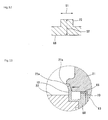
- the intervening elastic member 68 and the peripheral edge elastic member 72 are basically one body as shown in Figs. 8 , 11 , and 13 .
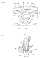
- the peripheral edge elastic member 72 is formed in outer circumference of the flange 22 than the receiving part 70 of the intervening elastic member 68, and as shown in Fig. 13 , it extends toward the housing 21.
- the top of the extension of the peripheral edge elastic member 72 is designed to abut the housing outer circumferential surface 21 a which is in the vicinity of flange side opening, and when at a time of abutting the top of the extension receives the pressure from the housing 21 to be compressed to deform in radial direction of the rotating shaft 12 toward outer edge of the flange 22.
- the top 72a of the extension of the peripheral edge elastic member 72 does not abut the housing 21 in the axial direction of the rotating shaft 12. As a result, the top 72a the top 72a of the extension is not compressed by the pressing force from the housing 21 in the axial direction of the rotating shaft 12.
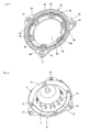
- the flange 22 includes a rib 74 that is constructed of a plurality of liner protrusions 73a to 73j.
- the rib 74 expresses a pattern that resembles turtle back pattern, which is a combination of; an innermost circular protrusion 73a, the center of which is facing the end of the rotating shaft 12; a circular protrusion 73b being located outside the circular protrusion 73a and forming a concentric circle with the circular protrusion 73a; a circular protrusion 73c being located outside the circular protrusion 73b and forming a concentric circle with the circular protrusions 73a and 73b; a linear protrusion 73d extending from a certain point of the circular protrusion 73c passing by way of the center point to another point of the circular protrusion 73c; and fin protrusions 73e, 73f, 73g, 73h, 73i, and
- the pattern of the rib 74 is not limited to the pattern shown in Fig. 9 , and any pattern may be utilized to minimize particular vibration characteristic of the flange 22.
- a honeycomb pattern formed by combining a plurality of hexagonal patterns may be acceptable.
- plate-shaped elastic member 75 made of material such as elastomer are filled as a vibration-proof material.
- Process of filling the plate-shaped elastic member 75 into the cells of the flange 22 includes attaching the member to the flange 22 by using adhesive or an adhesive seal, and filling elastomer by using injection molding to the cells of the injection-molded flange 22 (two-phase injection). Other processes may be appropriately selected depending on the environment where the driving motor 3 is used or the production cost.
- Fig. 14 shows the driving motor 3 having a modification of the intervening elastic member 68 inserted between the housing 21 and the flange 22.
- the intervening elastic member 68 of the driving motor 3 includes circular belt of plurality of grooves which are disposed in radial direction. Each groove may not extend to outer edge of the annular intervening elastic member 68.
- the receiving part 70 of the intervening elastic member 68 is of cylindrical structure with a through-hole 69 in it.
- the intervening elastic member 68 and its modification, the peripheral edge elastic member 72, and the plate-shaped elastic member 75 are shown and described as being used for the driving motor 3 for a large volume of air.
- the driving motor 3 for a small volume of air shown in Figs. 2 , 4 , and 5 may be configured to use the intervening elastic member 68 or its modification, the peripheral edge elastic member 72, and the plate-shaped elastic member 75, as described above.
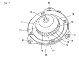
- the housing 21 may be configured to increase the surface area by forming a plurality of triangle ribs 77, as shown in Fig. 16 , or by forming a plurality of bump protrusions 78, as shown in Fig. 17 , further, although not shown, or by forming a plurality of recessed areas (dimples) protruding into inside of the housing 21.
- the rib 77, the protrusion 78 or the concave part functions as a heat dissipation accelerator to promote the dissipation of heat from the housing 21, and therefore, it is possible to effectively dissipate the heat from the housing 21.
- an outer rotor motor in which a rotor assembly rotates along the outer periphery of the stator assembly has been described; however, needless to say, the present invention can be applied to an inner rotor motor in which the rotor assembly rotates along the inner periphery of the stator assembly.
- the driving motor can be used in a blower unit of a vehicle air-conditioner.
Landscapes
- Engineering & Computer Science (AREA)
- Power Engineering (AREA)
- Mechanical Engineering (AREA)
- General Engineering & Computer Science (AREA)
- Physics & Mathematics (AREA)
- Thermal Sciences (AREA)
- Microelectronics & Electronic Packaging (AREA)
- Motor Or Generator Frames (AREA)
- Connection Of Motors, Electrical Generators, Mechanical Devices, And The Like (AREA)
Abstract
Description
- The present invention relates to a motor for driving a predetermined air-conditioning device such as a fan, where the motor being housed in a case with an air flow duct, such as a blower case of a blower unit, which may configure a vehicle air conditioner.
- In recent years, there is a need for a more efficient driving motor for a blower, smaller than a conventional motor, for a vehicle air conditioner or a ventilation device for a hybrid vehicle. Thus, there is required development of a driving motor having excellent water-proof and heat releasing characteristics, having a smaller size along the axial direction of a rotating shaft of a blower, and reducing the manufacturing cost.
- In this case, for example, a vehicle-mounted blower equipped with a brushless motor as mentioned in
Patent Document 1 is already known. The vehicle-mounted blower disclosed inPatent Document 1 is provided with a brushless motor that rotates a blower fan, a cooling fin molded in a single body in a metallic housing of the brushless motor, an auxiliary blade arranged in the blower fan to produce an air flow around the cooling fin, and a driving element closely attached to the housing. The objective thereof is to increase the cooling capacity of the motor driving element and reduce the size in a height direction of the blower as well as to take measures to curtail the manufacturing cost by reducing the number of parts. - Moreover, it is known that when an external air introducing mode is selected in the blower unit of the vehicle air conditioner and the external air is introduced from outside the vehicle interior, in case of rain, a misty rain water together with the external air enters the blower so that water drops adhere to electric devices such as an armature, contained in the driving motor and give rise to a problem of the insulation of the electric devices such as an armature, or a problem of rust such as in the component parts.
In response thereto, as mentioned inPatent Document 2, there is known a motor configured such that an interior space is formed by a metallic casing extended in an umbrella shape that opens from a rotating shaft bellow both blade wheel boss part and cone part that extends from the boss part, and a non metallic (for example, resin made) bottom plate that can cover a lower opening of this casing, the armature is housed in the interior space, and the casing and the bottom plate are fixed tightly and closely by screwing outwardly extending two flanges formed at the circumferential edge.
Moreover, there is already known a brushless motor as disclosed inPatent Document 3, for example. Although the brushless motor is directed at the use for a compressor unit of a home use air-conditioner rather than the blower unit of the vehicle air conditioner, it has a structure to prevent water from entering the motor interior-space when this compressor unit of the air conditioner is sprayed with water. In short, the brushless motor has a water-proof structure including a cylindrical casing. The cylindrical casing has a stator to be protected from water and is divided into left-right two cup-shaped casings at a vertical plane in the general center of the size of a rotating shaft direction. On a surface formed by connecting the left-right cup-shaped casings, a protrusion is arranged on one surface of the cup-shaped casing and a groove is arranged on the other surface of the cup-shaped casing, the protrusion is inserted into the groove, and an O-shaped ring is provided between the groove and the protrusion, whereby the left-right cup-shaped casings are air-tightly joined. - Moreover,
Patent Document 4 discloses a driving motor for a blower unit of a vehicle air conditioner having a structure wherein a rotor assembly is rotated by appropriately switching the magnetic power between a stator assembly and a rotor assembly, which are component parts of a magnetic circuit, and a rotating shaft is rotated along therewith. In this Document, it is known that magnetic vibrations are generated in a rotating direction (a radial direction of the rotating shaft) of the driving motor at the time of switching the magnetic power. Further, a driving motor for a blower unit of a vehicle air conditioner is disclosed inFig. 5 ofPatent Document 4. The driving motor is structured such that a rotor member such as a multi-blade fan is attached to one side end along an shaft direction of a rotating shaft and the rotor member is rotated to take in air and blow air in a predetermine direction. In this technology, it is known that there occurs a movement in which both ends of the rotating shaft rotate while drawing a circle as if to squeeze a pestle (hereinafter referred to as "precession") from various factors such as an air flow taken in or minute core misalignment of the rotating shaft. - If the two vibration components, magnetic vibration and vibration due to precession, are kept as it is, noise will be generated from the driving motor. In order to control these vibrations, a structure of the brushless motor is described in the claims of
Patent Document 4. The rotor is rotatably supported in the stator and the lower end of the center piece of the stator is fixed in the motor holder through a vibration-proof material. Then, the structure of a vibration-proof material of the brushless motor disclosed inPatent Document 4 is summarized by describing the detailed description ofPatent Document 4. The vibration-proof material is made of rubber having hardness from 20 to 40 in a generally cylindrical shape with a cylindrical through-hole in the central part. The inner diameter has the smallest size in the central region in the axial direction of the through-hole, and the inner diameter of the through-hole gradually expands towards the both openings. An annular groove is formed in the axial direction central region of the rubber cylinder outer surface. -
- Patent Document 1: Japanese Patent Application Laid-Open No.
10-191595 - Patent Document 2: Japanese Utility Model Application Laid-Open No.
2-139473 - Patent Document 3: Japanese Patent Application Laid-Open No.
10-304640 - Patent Document 4: Japanese Patent Application Laid-Open No.
2001-145300 - However, the brushless motor of the vehicle-mounted blower disclosed in
Patent Document 1 is configured such that the lower case is arranged at the lower side of the upper case to form a chamber for installing a control circuit-board. Because
the control circuit-board is stored in the this chamber, and the chamber has a convex portion bloated bellow the upper case, causes a problem that the vehicle-mounted blower has to be installed in the duct while the convex portion is protruding outside the duct. - The brushless motor of the vehicle-mounted blower disclosed in
Patent Document 1 has a problem that the structure becomes complex because the cooling fin which dissipates heat produced from the elements on the control circuit-board faces the blower fan side. As a result, the manufacturing cost of the brushless motor is also relatively high. Then, the brushless motor disclosed inPatent Document 1 has another problem that the component parts of the blushless motor is prone to rust due to insufficient water-proof measures, regardless of the blushless motor to be used in a vehicle-mounted blower. - Further, the brushless motor of the vehicle-mounted blower disclosed in
Patent Document 2 is configured such that the lower case is arranged at the lower side of the upper case to form the control circuit-board chamber in which the control circuit-board is installed, so that there is the convex portion bloated bellow the upper case. Thus, this motor has a problem that the vehicle-mounted blower has to be arranged in the duct while the convex portion is protruding outside the duct. - The brushless motor of the vehicle-mounted blower disclosed in
Patent Document 2 has a problem that the structure becomes complex because the cooling fin which dissipated heat produced from the elements on the control circuit-board is facing the blower fan. As a result, the manufacturing cost of the brushless motor is also relatively high. Then, the brushless motor disclosed inPatent Document 2 has another problem that the component parts of the blushless motor are easily rusted due to insufficient water-proof measures regardless of the blushless motor being used in a vehicle-mounted blower. - Moreover, when the vibration-proof material disclosed in
Patent Document 4 is used, the structure thereof is relatively complex and of particular design. Thus, the manufacturing cost of the vibration-proof material is relatively increased, and further, the manufacturing cost of the driving motor made of this vibration-proof material is relatively high. - Therefore, a first objective of the present invention is to meet a demand of making the length of a rotating shaft of the driving motor to be shorter in the axial direction. A second objective is to achieve a reduction in manufacturing cost and to ensure water-proof performance of a motor interior-space by inhibiting a vibration transmission to a flange by means of attenuating a transmission amount of a vibration component caused by rain water that flows in together with the wind. A third objective thereof is to reduce the noise generation and achieve an enhanced quietness by surely attenuating vibrations transmitted to the flange, absorbing a magnetic vibration through a sophisticated flange structure, and alleviating a resonant sound.
- The driving motor according to the present invention is a driving motor for transmitting a rotation force to a rotor member so as to rotate the rotor member, wherein a motor main body includes: a rotating shaft for rotating the rotor member which is attached to one end in an axial direction; a rotor assembly being attached to the rotating shaft and rotating together with the rotating shaft; a stator assembly facing to the rotor assembly in a radial direction of the rotating shaft and being arranged not rotating together with the rotating shaft; a control circuit-board that controls rotation of the rotating shaft as well as the rotor assembly; and a housing having a first opening which is formed in the relatively vicinity of the rotor member and a second opening relatively spaced apart from the rotor member, whereas the housing extends from around of the rotating shaft to outward in radial direction of the rotating shaft at the vicinity of one end, where it opens at the other end of the axial direction of the rotating shaft, and the housing at the other end of the axial direction of the rotating shaft is covered by a flange, thus the housing and the flange defines a motor interior-space, and the housing, being made of a metal, is attached to a case in which an air duct is defined inside so that an external surface of the housing is exposed to the air duct, and at least the stator assembly is contained in the motor interior-space of the housing (claim 1). Herein, examples of the rotor member include a multi-blade fan and other rotatable parts which are installed in the blower case of the blower unit.
- One end in the axial direction of the rotating shaft is protruding outwardly toward the rotor member side from the housing, and the other end in the axial direction of the rotating shaft is contained in the motor interior-space (claim 2).
- Aspects of the driving motor according to the invention include: a driving motor for a blower unit for a large volume of air, wherein the rotor assembly is also contained in the motor interior-space of the housing, the control circuit-board is arranged to be contained in the motor interior-space of the housing, being located in the vicinity of one end of the rotating shaft than the rotor assembly and the stator assembly in the axial direction of the rotating shaft, and a yoke is disposed to be contained in the motor interior-space of the housing, being located in the vicinity of the other end in the axial direction of the rotating shaft (claim 3); and a driving motor for a blower unit for a small volume of air, wherein the rotor assembly is also contained in the motor interior-space of the housing, the control circuit-board is arranged to be contained in the motor interior-space of the housing, being located in the vicinity of the other end of the rotating shaft than the rotor assembly and the stator assembly in the axial direction of the rotating shaft, a yoke is disposed to be contained in the motor interior-space of the housing, being located in the vicinity of one end in the axial direction of the rotating shaft.
- With these configurations, all the parts arranged bellow the flange in the conventional driving motors are arranged above the flange, and thus, a lower case attached bellow the flange is eliminated. As a result, the lower side of the driving motor is formed in a flat shape, and the size along the axial direction of the rotating shaft of the driving motor is made relatively smaller than the thickness of the lower case of the conventional driving motors.
- The driving motor according to the present invention is characterized in that an elastic ring member is provided in a cylindrical gap between the first opening of the housing and the rotating shaft (claim 5). Therefore, the first opening of the housing and the rotating shaft are sealed, and therefore, there is no gap therebetween. As a result, it is possible to prevent water such as rain water from entering the motor interior-space through the gap between the first opening of the housing and the rotating shaft, and it is also possible to prevent the transmission of the rotation vibration from the rotating shaft to the housing because of the elasticity provided by the elastic ring member.
- On the other hand, the driving motor according to the present invention may be characterized in that the rotor member includes a cone part that has a boss part to which the rotating shaft is fixed, the cone part which has a boss part and a first cylindrical part, which is positioned in outer circumference of the rotating shaft than the boss part and extending in axial direction toward the opposite end of the rotating shaft, while the housing has a second cylindrical part which extends in the axial direction of the rotating shaft to the boss part of the cone part and its outer radius being smaller than an inner radial size of the first cylindrical part, and it also has a first opening in which the rotating shaft is to be inserted the circumferential part of the first opening being extending toward the rotating shaft so as to form a flange, with witch, at a time of assembling the driving motor and the rotor member, the second cylindrical part, being housed in the first cylindrical part generates a space in a relatively complex manner (claim 6). This eliminates a need for the provision of the elastic ring member, and thus, the number of parts of the driving motor can be reduced.
- The driving motor according to the present invention is characterized in that the rotating shaft, the rotor assembly, and the stator assembly which are integrally formed as a vibrator, and the vibrator is fixed to the flange through a elastic mounting member (claim 7). As a result, the interposed elastic mounting member can attenuate the transmission amount of vibrations, and thus, it is possible to inhibit the transmission of the vibration components from the vibration source to the flange.
- The driving motor according to the present invention is characterized in that an elastic member is interposed between the housing and the flange at a time of covering the second opening side of the housing, the intervening elastic member to include three or more receiving parts each having a surface to interface the housing end surface which is opposing to the flange, wherein the receiving parts being arranged to surround the rotating shaft to support the motor main body (claim 8). As a result, when the second opening side of the housing is covered by the flange, the flange indirectly abuts the housing with the intervening elastic member in between. Thus, it is possible to inhibit a magnetic vibration, generated from component parts of a magnetic circuit or a vibration resulting from the precession of a rotating shaft, transmitted from the housing to the flange. Further, because the motor main body is supported in the receiving part and a contact area between the housing and the flange is reduced, silent rotation of the driving motor to can be realized. Moreover, the fact that the receiving parts are arranged at three locations or more to surround the rotating shaft makes the flange and the housing stably positioned, which can more effectively reduce precession.
- It is preferable that the intervening elastic member is configured such that a spring constant in a rotating direction of the rotating shaft is smaller than a spring constant in an axial direction of the rotating shaft (claim 10). That is because the spring constant in the rotating direction of the rotating shaft is a numerical value corresponding to a magnetic vibration. The spring constant in the axial direction of the rotating shaft is a numerical value corresponding to a precession.
- On the other hand, the driving motor according to the present invention may be characterized in that an elastic member is interposed between the housing and the flange at a time of covering the second opening side of the housing, the intervening elastic member to include a plurality of liner grooves in an area opposing to the second opening of the housing (claim 9). As a result, a vibration absorption effect of the intervening elastic member can be enhanced, and thus, it is possible to achieve a further noise reduction of the driving motor.
- The driving motor according to the present invention is characterized in that the flange, at a time of covering the second opening side of the housing, the flange to includes a peripheral edge elastic member on its surface which is facing the second opening of the housing ,whereas the peripheral edge elastic member being compressed by a pressing force generated by the housing in roughly a radial direction of the rotating shaft, while at the same time the peripheral edge elastic member contacts a region near the second opening on an outer peripheral surface of the housing so that a compressing force does not work in the axial direction of the rotating shaft (claim 11). Since peripheral edge elastic members are arranged in radial outer area of the flange surface which is facing the second opening of the housing, the inner surface in the radial direction of the rotating shaft of the peripheral edge elastic member contacts the housing, so that the plastic member is pressed by the housing toward the radial external side of the rotating shaft to be in compressed state. Consequently, water such as rain water can not enter the motor interior-space from the gap between the peripheral edge elastic member and the housing, thus the peripheral edge elastic member provides water-proof effect At the same time, there is no pressing force by the housing onto the surface in the axial direction, and thus, the peripheral edge elastic member is not compressed along the axial direction of the rotating shaft. As a result, it is possible to inhibit the transmission of the vibration component such as the magnetic vibration or the rotation vibration from the housing to the flange, and therefore, it is possible to provide a vibration attenuation effect by the peripheral edge elastic member.
- The driving motor according to the present invention may be configured such that a heat dissipation accelerator for enhancing dissipation of heat generated in the motor interior-space to outside the motor interior-space is arranged on a surface facing the rotor member (claim 12). Herein, examples of the heat dissipation accelerator include a liner rib extending along the axial direction of the rotating shaft, a plurality of protrusions, and a plurality of recesses (dimples). These eliminate a need of providing a heat dissipation device such as a cooling fin and a heat sink.
- The driving motor according to the present invention may be configured such that a surface facing the second opening of the housing of the flange has a rib which consists of a plurality of liner protrusions extending toward the housing (claim 13). Examples of the rib further include one which consists of both a plurality of liner protrusions radially extending toward the outer edge side from the rotating shaft and a plurality of liner protrusions concentrically arranged at predetermined intervals, where the rotating shaft is a center point, another one which has a plurality liner protrusions are arranged in a honeycomb shape, and another which has a plurality of liner protrusions are arrange in a hexagonal shape. As a result, the rigidity of the flange is relatively improved by the rib, the conventionally generated resonant sound due to the magnetic vibration resulting from the deformation of the flange surface can be reduced, and the magnetic vibration can be absorbed by the vibration-proof elastic member.
- Thus, according to these inventions, the metal housing that contains at least the stator assembly covers the stator assembly from above like an umbrella shape; it is possible to provide the stator assembly with a water-proof function. In addition, since the housing which is made of metal of excellent thermal conductivity contains the stator assembly in it and the external surface of it is exposed to an air duct of a case such as a blower case, the heat from the stator assembly is transmitted to the housing, and the heat from the control circuit-board is also transmitted to the housing. Accordingly, the external surface of the housing faces the air duct of the case, heat generated from the stator assembly can be easily dissipation from the external surface of the housing. As a result, it is possible to promote a decrease of a temperature of the whose driving motor. This eliminates a need of a heat dissipation device such as a heat sink, and thus, the driving motor can be made compact and manufacturing cost of the motor can be reduced while keeping excellent heat dissipation.
- In particular, according to the invention described in
claim 2, all the components arranged bellow the flange in the conventional driving motors are arranged upper side of the flange, and therefore, a need of a lower case attached at a lower portion of the flange in the conventional driving motors can be eliminated. As a result, the lower portion of the driving motor can be formed in a flat shape, and the size in the axial direction of the rotating shaft of the driving motor can be relatively made smaller by the thickness of the lower case of the conventional driving motors. Thus, it is possible to achieve a compact-sized driving motor, and even when the blower unit is installed in the duct, it is possible to prevent one portion of the driving motor from protruding to outside the duct, which results in improvement of the driving motor, as well as of the blower unit, in terms of layout. - Particularly, according to the inventions described in
claims claims - Particularly, according to the invention described in
claim 5, since the gap between the first opening of the housing and the rotating shaft are air-tightly covered by interposing a elastic ring member, there is no gap between the first opening of the housing and the rotating shaft. As a result, it is possible to prevent water such as rain water from entering the motor interior-space through the gap, and it is also possible to prevent the transmission of the rotation vibration from the rotating shaft to the housing because the elastic ring member can attenuate the vibration. - Particularly, according to the invention described in
claim 6, it is possible to prevent water such as rain water from entering the motor interior-space through a gap between the first opening of the housing and the rotating shaft even when the elastic ring member is not provided. Thus, the need of the elastic ring member can be eliminated, and the component count of the driving motor can be reduced. As a result, it is possible to reduce a manufacturing cost of the driving motor. - Particularly, according to the invention described in
claim 7, the elastic mounting member that is inserted in the first opening can attenuate the transmission amount of the vibration component, and therefore, it is possible to inhibit the transmission of the vibration component from the vibration source to the flange. - Particularly, according to the invention described in
claims 8 and claim 10, when the second opening of the housing is covered in a flange surface region facing the housing, the flange indirectly abuts the housing with the intervening elastic member in between , and the abutting area facing the second opening of the housing is relatively small, it is possible to prevent the transmission of a magnetic vibration generated from component parts of a magnetic circuit such as a rotor assembly and a vibration resulting from a precession of a rotating shaft from the housing to the flange, and it is possible to enhance the quietness of the driving motor. - Particularly, according to the invention described in
claim 9, a vibration absorption effect can be enhanced by the intervening elastic member, and thus, it is possible to achieve a further noise reduction of the driving motor. - Particularly, according to the invention described in
claim 11, since a peripheral edge elastic member is disposed in outer region in axial direction of the flange that is facing the second opening of the housing, and the inner surface in radial direction of the peripheral edge elastic member contacts the housing, the elastic member is pressed toward radial external direction and it is in compressed state. Therefore, the peripheral edge elastic member adheres closely to the outer peripheral surface of the housing, and water such as rain water does not enter the motor interior-space from the gap between the peripheral edge elastic member and the housing. As a result, it is possible to provide the peripheral edge elastic member with a water-proof effect. Moreover, there is no axial direction pressing force by the housing onto the surface of the peripheral edge elastic member, thus the peripheral edge elastic member is not compressed along the axial direction of the rotating shaft. As a result, it is possible to suppress the transmission of the magnetic vibration or the rotation vibration from the housing to the flange, and therefore, it is possible to provide the peripheral edge elastic member with a vibration insulation effect. This eliminates a need of applying a seal material for a water-proof to components of the motor disposed in the motor interior-space to realize a simple structure. Thus, it is possible to prevent the generation of noise from the driving motor while suppressing an increase of number of manufacture processes of the driving motor and an increase in manufacturing cost. - Particularly, according to the invention described in
claim 12, it is not necessary to provide a heat dissipation device such as a cooling fin and a heat sink, and thus, it is possible to achieve a reduction in manufacturing cost of the driving motor. - Particularly, according to the invention described in
claim 13, a vibration attenuation is enhanced by a vibration-proof elastic member, and thus, it is possible to achieve a further reduction of noise from the driving motor. -
-
Fig. 1(a) is a diagram explaining a blower unit and a blower case storing the blower unit, using a driving motor for a small volume of air of the driving motor according to the present invention, andFig. 1(b) is a cross section view taken along A-A line ofFig. 1 (a) . -
Fig. 2 is a cross section view showing the configuration of the above described driving motor for a small volume of air. -
Fig. 3 is a half-cross section view showing the structure of an elastic ring member of the above described driving motor for a small volume of air. -
Fig. 4 is a cross section view showing a modification in which the need of the insertion of the elastic ring member to a cylindrical gap between a housing and a rotating shaft is eliminated, of the driving motor for a small volume of air shown inFig. 2 . -
Fig. 5 is a cross section view showing the configuration having an elastic mounting member in the driving motor for a small volume of air of the present invention. -
Fig. 6(a) is an explanatory view showing the configuration of a control circuit-board, in particular, the configuration of its bottom surface side, used for the driving motor having above described elastic mounting member, andFig. 6(b) is an explanatory view showing the configuration of a flange used for the driving motor having above described elastic mounting member, in particular, the configuration of the top surface of the flange. -
Fig. 7(a) is a diagram explaining a blower unit and a blower case which contains the blower unit, where a large capacity driving motor of the present invention is described, andFig. 7(b) is a cross section view taken along B-B line ofFig. 7(a) . -
Fig. 8 is a cross section view showing the configuration of above described driving motor for a large volume of air. -
Fig. 9 is a plan view showing a state in which a flange of above described driving motor for a large volume of air is viewed from a housing side. -
Fig. 10 is an enlarged view showing the configuration of an intervening elastic member, a peripheral edge elastic member, and a receiving part of above described flange. -
Fig. 11 is a cross section view showing a state in which the intervening elastic member, the peripheral edge elastic member, and the receiving part of the above-described flange are combined. -
Fig. 12 is an explanatory view explaining a spring constant of above described intervening elastic member. -
Fig. 13 is a further enlarged view ofFig. 11 to show the configuration of the peripheral edge elastic member. -
Fig. 14 is a cross section view showing the configuration of another modification of the peripheral edge elastic member of the driving motor for a small volume of air of the present invention. -
Fig. 15 is a plan view showing a state in which the flange of the driving motor having the modification of above described peripheral edge elastic member is viewed from a housing side. -
Fig. 16 is an explanatory view showing the configuration of a heat dissipation accelerator arranged in the housing of the driving motor. -
Fig. 17 is an explanatory view showing the configuration of a driving motor heat dissipation accelerator which is different from the one shown inFig. 16 , where another example of heat dissipation construction is described. - Hereinafter, embodiments of the present invention will be described with reference to the accompanying drawings.
- A
blower unit 1 shown inFig. 1 is situated in downstream of a battery for cooling the battery (not shown) and is used to inhales the heated air from the battery and to dissipate outside. Here, theblower unit 1 is designed for a small air volume, and includes a scroll-shapedblower case 2, a drivingmotor 3, and amulti-blade fan 4. - The
blower case 2 is made of resin or the like, and includes: anupper side wall 7 having anopening 6 where abell mouth 5 is formed integrated or separately; alower side wall 9 that is arranged to face theupper side wall 7 at a predetermined interval and having therein amotor insertion hole 8 into which the drivingmotor 3 is installed; and an outerperipheral wall 10 situated to connect outer peripheral edges of theupper side wall 7 and thelower side wall 9 while providing aexhausting outlet 11 between them. The outerperipheral wall 10 starts from a windingstart portion 10a, and is formed in spiral shape so that a distance from the center of themulti-blade fan 4 to the wall gradually increases along a circumferential direction of themulti-blade fan 4. - The
multi-blade fan 4 itself is well known and, as shown inFigs. 1 ,2 ,4 and5 , it includes: aboss part 13 fixed to arotating shaft 12, described bellow, of the drivingmotor 3; acone part 14 which is extending from theboss part 13; a plurality ofblades 15 that are disposed in an upright position along the axial direction of therotating shaft 12 and disposed along the circumferential direction of the outer peripheral edge of thecone part 14. In this configuration, the air flown in from aninlet 16 defined by theblades 15 and facing thecone part 14 is guided to the side of theblade 15 along thecone part 14 and passed through between theblade 15 and theblade 15. - In the driving
motor 3, a motormain body 23 includes: the rotatingshaft 12; aboss housing 17; astator assembly 18 attached on the outer peripheral surface of theboss housing 17; a control circuit-board 19; arotor assembly 20; ahousing 21; and aflange 22, as shown inFigs. 1 ,2 ,4 and5 . - Among these components, the rotating
shaft 12 is formed in a generally circular rod shape. The rotatingshaft 12 enables rotation of a rotor member, such as amulti-blade fan 4, which are attached to the upper end in the longitudinal direction of therotating shaft 12. In addition, the rotatingshaft 12 is rotatably supported bybearings cylindrical boss housing 17 that is extending from thehousing 21 downward in the axial direction of therotating shaft 12. Thebearings space 50 described below. - Further, the
stator assembly 18 is disposed on the outer peripheral surface of theboss housing 17, wherein the outer peripheral surface is extending downward in the axial direction of therotating shaft 12. Thisstator assembly 18 consists of an iron core and an armature winding which are wound multiple times around the outer peripheral surface at the side of the core. - The
rotor assembly 20 is attached to therotating shaft 12 at an upper position in the axial direction of therotating shaft 12 above thestator assembly 18. Thisrotor assembly 20 faces thestator assembly 18 in the radial direction of therotating shaft 12, and it consists of ayoke 26 andmagnets 27 which are positioned on the inner side surface of theyoke 25 to face the armature winding of thestator assembly 18. Themagnets 27 are made of sintered ferrite, for example. - With this driving
motor configuration 3, a rotating magnetic field resulting from thestator assembly 18 rotates therotor assembly 20, which further makes therotating shaft 12 rotate. - Further, the driving
motor 3 includes a relatively thin-plate control circuit-board 19, on which electronic parts to control switching of a current fed to the armature winding of thestator assembly 18 through an electronic switch or the like are disposed. More specifically, the control circuit-board 19 includes aheat radiation part 29 such as acapacitor 28 and a transistor. In addition, in this embodiment, the control circuit-board 29 is situated in the lower end in the axial direction of therotating shaft 12 than thestator assembly 18 and therotor assembly 20, and theheat radiation part 29 such ascapacitors 28 and transistors are also situated at the bottom surface side of the control circuit-board 19. - The
housing 21 gradually increases its diameter from at around the rotatingshaft 12 at the same time in the vicinity of theboss part 13 to the opposite end of theshaft 12 in the axial direction. The housing has opening at the opposite end of theboss part 13 to make an umbrella like structure as a whole, and it is cylindrical in that is has a first opening at themulti-blade fan 4 side and a second opening at theflange 22 side. Further, thehousing 21 is made of a material which has excellent thermal conductivity, for example, metal such as aluminum. - The
flange 22 can cover the second opening which is the other opening made at the opposite end of the housing close to theboss part 13, and it has a recessedpart 30 at the central region which is facinghousing 21 side. The recessedpart 30 preferably may have enough volume to contain small electronic parts such ascapacitors 28 and transistors, size in the axial direction of therotating shaft 12 being equal to or less than 10 mm, for example. Further, theflange 22 is made of a material, for example, resin such as polypropylene (PP) resin. Otherwise, theflange 22 could be made of a metal as the material. - The flange of the driving
motor 3 shown inFigs. 2 and4 , as wall as shown inFig. 6(b) , has aconcave part 31, at the peripheral edge that can meet at least theperipheral collar part 21 a of thehousing 21 is formed. A plurality ofprotrusions 32 are arranged on the bottom surface of the recessedpart 30 of theflange 22, and aninsertion part 32a is formed at the top of theprotrusion 32, as shown inFig. 6(b) . Theinsertion part 32a of theprotrusion 34 can be inserted into aninsertion hole 33 formed in the back surface of the control circuit-board 18 shown inFig. 6(a) , accordingly, as shown inFigs. 2 and4 , theinsertion part 32a together with theprotrusion 32 play a role of a stud to support the control circuit-board 19 from theflange 22 side. - In the driving
motor 3 ofFig.5 , the recessedpart 30 and theprotrusion 32 are not shown because the position of the cross section of the drivingmotor 3 is different from the drivingmotor 3,for example shown inFigs. 2 and4 . Unlike this embodiment, the drivingmotor 3 shown inFig. 5 may also has the recessedpart 30 like that shown in shown inFigs. 2 and4 , where theprotrusion 32 are configured to be inserted into theinsertion hole 33 of the control circuit-board 19 so that the control circuit-board 19 is secured from theflange 22 side. - Therefore, by securing the
housing 21 and theflange 22 together making use of abolt 34, a motor interior-space 35 is formed in the drivingmotor 3, as shown inFigs. 2 ,4 , and5 . The motor interior-space 35 can hold the control circuit-board 19 and at least the end portion, the opposite side of theboss part 13, of therotating shaft 12, and further holds thestator assembly 18 and therotor assembly 20 in a space above the control circuit-board 19. Since the motor interior-space 35 has the recessedpart 30 of theflange 22 to form a lower space below the control circuit-board 19, theheat radiation part 29 such ascapacitors 28 and transistors are disposed. - Therefore, in the driving
motor 3 for a small volume of air, all the parts can be disposed above theflange 22 unlike in the conventional driving motors where parts are disposed bellow theflange 22, accordingly, a lower case attached bellow theflange 22 in the conventional driving motors is eliminated. As a result, as shown inFigs. 1(b) ,2 ,4 , and5 , the lower surface of the drivingmotor 3 is formed in an generally flat, and since the drivingmotor 3 does not stick to outside, the duct can be avoided even when theblower unit 1 is arranged in the duct, and the drivingmotor 3 can be improved in terms of layout when theblower unit 1 is mounted on a vehicle, etc. In addition, as a result of the drivingmotor 3 configured in this way, the size H1 (shown inFig. 1(b) ) along the axial direction of therotating shaft 12 of the drivingmotor 3 can be made relatively smaller by the thickness of the lower case of the conventional driving motors. - The
housing 21 of the drivingmotor 3 for a small air volume, as shown inFig. 1 (b) , has its outer surface exposed to anair duct 36 of theblower unit 1, and further, thehousing 21 is made of a material which has excellent thermal conductivity, for example a metal such as aluminum, as described above. As a result, even if the control circuit-board 19 or thestator assembly 18 contained in thehousing 21 generates heat, the outer surface (especially lateral outer surface) of thehousing 21 is exposed to theair duct 36, and therefore, the heat generated from the control circuit-board 19 and thestator assembly 18 is transmitted to the highly thermalconductive housing 21 and is dissipated from the outer surface of thehousing 21. This heat dissipation mechanism enables simple structure of the drivingmotor 3 without using a heat dissipation device such as a heat sink. At the same time, a manufacturing cost of theblower unit 1 can be relatively reduced due to the reduced number of parts, and theblower unit 1 can be further made smaller as well as the drivingmotor 3. - A
blower unit 1 shown inFig. 7 is situated in downstream of a battery for cooling the battery (not shown) and is used to inhales the heated air from the battery and to dissipate outside. Here, theblower unit 1 is designed for a large air volume, and includes a scroll-shapedblower case 2, a drivingmotor 3, and amulti-blade fan 4. - The
blower case 2 is made of resin or the like, and includes: anupper side wall 7 having anopening 6 where abell mouth 5 is formed integrated or separated; alower side wall 9 that is arranged to face theupper side wall 7 at a predetermined interval and having therein amotor insertion hole 8 into which the drivingmotor 3 is installed; and an outerperipheral wall 10 situated to connect outer peripheral edges of theupper side wall 7 and thelower side wall 9 while providing aexhausting outlet 11 between them. The outerperipheral wall 10 starts from a windingstart portion 10a, and is formed in spiral shape so that a distance from the center of themulti-blade fan 4 to the wall gradually increases along a circumferential direction of themulti-blade fan 4. - The
multi-blade fan 4 itself is well known and, as shown inFigs. 7 ,8 and14 , it includes: aboss part 13 fixed to arotating shaft 12, described bellow, of the drivingmotor 3; acone part 14 which is extending from theboss part 13; a plurality ofblades 15 that are disposed in an upright position along the axial direction of therotating shaft 12 and disposed along the circumferential direction of the outer peripheral edge of thecone part 14. In this configuration, the air flown in from aninlet 16 defined by theblades 15 and facing thecone part 14 is guided to the side of theblade 15 along thecone part 14 and passed through between theblade 15 and theblade 15. - In the driving
motor 3, a motormain body 23 includes: the rotatingshaft 12; aboss housing 17; astator assembly 18 attached on the outer peripheral surface of theboss housing 17; a control circuit-board 19; arotor assembly 20; ahousing 21; and aflange 22, as shown inFigs. 7 ,8 and14 . - Among these components, the rotating
shaft 12 is formed in a generally circular rod shape. The rotatingshaft 12 enables rotation of a rotor member, such as amulti-blade fan 4, which are attached to the upper end in the longitudinal direction of therotating shaft 12. In addition, the rotatingshaft 12 is rotatably supported bybearings cylindrical boss housing 17 that is extending from thehousing 21 downward in the axial direction of therotating shaft 12. And the rotatingshaft 12 is not connected to the flange. Thebearings space 35 described below. - Further, the
stator assembly 18 is disposed on the outer peripheral surface of theboss housing 17, wherein the outer peripheral surface is extending downward in the axial direction of therotating shaft 12. Thisstator assembly 18, shown in Fig.18, consists of aslot insulator 37, acore 38 andarmature windings slot insulator 37 includes anupper side region 37a situated at an upper side (opposite side of the flange 22) in the axial direction of therotating shaft 12, and alower side region 37b situated at a lower side (at the side of the flange 22) in the axial direction of therotating shaft 12. Between theupper side region 37a and thelower side region 37b of theslot insulator 37, acore part 38 made of iron for example is sandwiched. Each ofarmature windings upper side region 37a and thelower side region 37b of theslot insulator 37. - The
rotor assembly 20 is attached to therotating shaft 12 at a lower position in the axial direction of therotating shaft 12 bellow thestator assembly 18. Thisrotor assembly 20 faces thestator assembly 18 in the radial direction of therotating shaft 12, and it consists of ayoke 26 andmagnets 27 which are positioned on the inner side surface of theyoke 26 to face thecore part 28 of thestator assembly 18. Themagnets 27 are made of sintered ferrite, for example. - With this driving
motor configuration 3, a rotating magnetic field resulting from thestator assembly 18 rotates therotor assembly 20, which further makes therotating shaft 12 rotate. - Further, the driving
motor 3 includes a control circuit-board 19, on which electronic parts to control switching of a current fed to the armature winding 39, 40 of thestator assembly 18 by means of an electronic switch or the like are disposed. The control circuit-board 19 includes aheat radiation part 29 such as capacitors and transistors. As shown inFig.8 , the control circuit-board 19 is secured by a fixingmember 41 such as a screw to theupper side region 37a in theslot insulator 37 of thestator assembly 18, and is positioned, higher than thestator assembly 18 and therotor assembly 20, in the upper end area of the axial direction of therotating shaft 12. Further, inFig. 14 , the control circuit-board 19 is secured by the fixingmember 41 such as a screw onto the inner side surface of thehousing 21 of the drivingmotor 3, and is positioned, higher than thestator assembly 18 and therotor assembly 20, in the upper end area of the axial direction of therotating shaft 12.. -
Silicon grease 42 is applied around theheat radiation part 29. As a result, heat generated from theheat radiation part 29 is transmitted to thehousing 21, as described bellow, through thesilicon grease 42 and is dissipated outside from thehousing 21. - The
housing 21 as shown inFig.8 andFig.14 gradually increases its diameter from at around the rotatingshaft 12 at the same time in the vicinity of theboss part 13 to the opposite end of theshaft 12 in the axial direction. The housing has opening at the opposite end of theboss part 13 to make an umbrella like structure as a whole, and it is cylindrical in that is has a first opening at themulti-blade fan 4 side and a second opening at theflange 22 side. Further, thehousing 21 is made of a material which has excellent thermal conductivity, for example, metal such as aluminum. In this embodiment, thehousing 21 includes aboss housing 17 which extend downward from near the first opening of the inner surface along the axial direction of the rotating shaft. - The
flange 22 which can cover the second opening of thehousing 21 is made of polypropylene (PP) resin, etc. and thus, as shown inFigs. 8 and14 , it has a recessedpart 30 at the central region which is facinghousing 21 side. In fact, the recessedpart 30 is a very small space, having depth of only 10mm or less, for example. Further, theflange 22 may be made of iron, for example. InFig. 8 , theflange 22 has anextension 43 extending outward from theflange 22 for securing the drivingmotor 3 to another device like ablower case 2 of ablower unit 1 of a vehicle air conditioner. Eachextension 43 has a through-hole 43a for this purpose. It is noted that, although not shown, a through-hole may be formed similarly in theextension 43 of theflange 22 of the drivingmotor 3 shown inFig. 14 to be used for securing the drivingmotor 3 to theblower case 2 of theblower unit 1. - Therefore, by securing the
housing 21 and theflange 22 together making use of abolt 34, a motor interior-space 35 is formed in the drivingmotor 3, as shown inFigs. 8 and14 . The motor interior-space 35 can hold the control circuit-board 19 and at least the end portion, the opposite side of theboss part 13, of therotating shaft 12, and further holds thestator assembly 18 and therotor assembly 20 in a space bellow the control circuit-board 19. - As a result, in case of the driving
motor 3 for a large volume of air, similar mechanism to that of drivingmotor 3 for a small volume of air works and similar results, as described earlier, are obtained. Therefore, in the drivingmotor 3 for a small volume of air, all the parts can be disposed above theflange 22 unlike in the conventional driving motors where parts are disposed bellow theflange 22, accordingly, a lower case attached bellow theflange 22 in the conventional driving motors is eliminated. As a result, as shown inFigs. 7(b) ,8 , and14 , the lower surface of the drivingmotor 3 is formed in an generally flat, and since the drivingmotor 3 does not stick to outside, the duct can be avoided even when theblower unit 1 is arranged in the duct, and the drivingmotor 3 can be improved in terms of layout when theblower unit 1 is mounted on a vehicle, etc. In addition, as a result of the drivingmotor 3 configured in this way, the size H2 (shown inFig. 7(b) ) along the axial direction of therotating shaft 12 of the drivingmotor 3 can be made relatively smaller by the thickness of the lower case of the conventional driving motors.. - The
housing 21 of the drivingmotor 3 for a large air volume, as shown inFig. 7(b) , has its outer surface exposed to anair duct 36 of theblower unit 1, and further, thehousing 21 is made of a material which has excellent thermal conductivity, for example a metal such as aluminum, as described above. As a result, even if the control circuit-board 19 or thestator assembly 18 contained in thehousing 21 generates heat, the outer surface (especially lateral outer surface) of thehousing 21 is exposed to theair duct 36, and therefore, the heat generated from the control circuit-board 19 and thestator assembly 18 is transmitted to the highly thermalconductive housing 21 and is dissipated from the outer surface of thehousing 21. This heat dissipation mechanism enables simple structure of the drivingmotor 3 without using a heat dissipation device such as a heat sink. At the same time, a manufacturing cost of theblower unit 1 can be relatively reduced due to the reduced number of parts, and theblower unit 1 can be further made smaller as well as the drivingmotor 3. - It is noted that in the first opening (multi-blade fan side) of the
housing 21 of the drivingmotor 3 for a small volume of air shown inFigs. 2 and5 , ancylindrical gap 44 is created between thehousing 21 and the lateral periphery surface of therotating shaft 12, and it is extending along the axial direction of therotating shaft 12. And anelastic ring member 45 is inserted in thecylindrical gap 44. - This
elastic ring member 45 is formed of a material such as nitride rubber (NBR) and has elasticity. As shown inFig. 3 , theelastic ring member 45 includes: abottom wall part 47 of an annular plate having acircular hole 46 at the center; an outerperipheral wall part 48 which is extending from the outer peripheral edge of thebottom wall part 47 in the axial direction of thecircular hole 46, and it contacts the inner peripheral surface of theflange 22 when it is inserted in thecylindrical gap 44; and an innerperipheral wall part 49 thickness of which gradually reduces from the inner peripheral edge of thebottom wall part 48 along the axial direction of thecircular hole 46, at the same time thewall part 49 being extending in an oblique direction, and oblique extension contacts circumference edge surface of therotating shaft 12 when it is inserted in thecylindrical gap 44. In this embodiment ofFig.3 theelastic ring member 45 has a built-insheet spring 50 which is inserted between the outerperipheral wall part 48 and thebottom wall part 47. - As a result, the
elastic ring member 45 is inserted air-tightly between thehousing 21 and therotating shaft 12 at the same time allowing rotation of therotating shaft 12. This prevents water from entering the motor interior-space 35 from outside thehousing 21 through the gap between thehousing 21 and therotating shaft 12, and it becomes possible to suppress the magnetic vibration and the rotation vibration of therotating shaft 12 from being transmitted to thehousing 21. - The
elastic ring member 45 which is applied to the drivingmotor 3 for a small volume of air has been illustrated; however, theelastic ring member 45 can also be applied to the drivingmotor 3 for a large volume of air shown inFigs. 8 and14 . That is, in case of the drivingmotor 3 for a large volume of air shown inFigs. 8 and14 , when the cylindrical gap is arranged between thehousing 21 and the lateral peripheral surface of therotating shaft 12 in the first opening, which is themulti-blade fan 4 side of the shaft, then it is possible to provide theelastic ring member 45 in the cylindrical gap in the same way with in case of the drivingmotor 3 for a small volume of air,. - The driving
motor 3 for a small volume of air may be modified to have noelastic ring member 45 by means of assembling thehousing 21 and thecone part 14 which contains a rotor member like amulti-blade fan 4. That is, thecone part 14 has acylindrical part 51 which, in the outer region surrounding the boss, extends from the vicinity of the boss toward the motor interior-space 35 (toward opposite end in the axial direction of the rotating shaft 12) along the rotatingshaft 12. Thehousing 21 at the same time has acylindrical part 52 extending toward the boss part 13 (opposite end in the axial direction of the rotating shaft 12) along the rotatingshaft 12. The outer radius of thecylindrical part 52 is relatively smaller than the inner radial size of thecylindrical part 51. On the other hand, the inner radial is large enough to be able to create thecylindrical gap 53 between thehousing 21 and therotating shaft 12. The boss side end of thecylindrical part 52 has aninsertion hole 54 through which therotating shaft 12 can be inserted. And from the peripheral edge of theinsertion hole 54, theflange 55 is extending toward the rotating shaft 12in the radial direction of therotating shaft 12. - As a result, when assembling the rotor member such as the
multi-blade fan 4 and the drivingmotor 3 , thecylindrical part 52 of thehousing 21 is housed in thecylindrical part 51 of thecone part 14, and the gap between thecylindrical part 51 and thecylindrical part 52 is divided into a complex space (labyrinth space) to form a portion extending along the axial direction of therotating shaft 12, and another portion, above the previous portion, extending along the radial direction of therotating shaft 12. Therefore, it is possible to stop the external water from entering the motor interior-space 35 from theinsertion hole 54 and thecylindrical gap 53, and it is also possible to eliminate a need of theelastic ring member 45. - It is noted that the driving
motor 3 for a large volume of air shown inFigs. 8 and14 can be also modified, not shown, similar to above description, to have a construction, where thecylindrical part 52 of thehousing 21 is housed in thecylindrical part 51 of thecone part 14, and the gap between thecylindrical part 51 and thecylindrical part 52 is divided into a complex space (labyrinth space) to form a portion extending along the axial direction of therotating shaft 12, and another portion, above the previous portion, extending toward the radial direction of therotating shaft 12. Then it is also possible to eliminate the need of theelastic ring member 45. - Moreover, in the driving
motor 3 for a small volume of air shown inFigs. 2 ,4 , and5 , the rotatingshaft 12, theboss housing 17, therotor assembly 20, and thebearings rotating shaft 12, theboss housing 17, therotor assembly 20, and thebearings Fig. 5 . As shown inFigs. 5 and6 (a) , in a lower region of theboss housing 17, there are disposed a plurality ofsupport arm 56 which is radially extending toward the outside in the radial direction of therotating shaft 12. At the distal end of thesupport arm 56, aprotrusion 57 is disposed and is extending downward. When theflange 22 and thehousing 21 are assembled, anotch 58 is formed in theflange 22 as shown inFigs. 5 and6 (b) at a position corresponding to theprotrusion 57 of thesupport arm 56. The elastic mountingmember 59 is then attached to thenotch 58. In addition, aninsertion hole 60 through which theprotrusion 57 of thesupport arm 56 can be inserted is formed in the elastic mountingmember 59, whereliner grooves 61 extends radially from theinsertion hole 60. - As a result, vibration from the rotating
shaft 12, theboss housing 17, therotor assembly 20, and thebearings motor 3, is transmitted to theflange 22 through the elastic mountingmember 59, and thus, the vibration is attenuated by the elastic mountingmember 59, and consequently, amount of vibration to theflange 22 can be reduced. - Additionally, as shown in
Fig. 6 (a) , a connectingdevice 62 having a spring function is disposed in the back surface side of the control circuit-board 19. The connectingdevice 62 secures an electric conduction between the control circuit-board 19 and thestator assembly 18, as well as attenuates the transmission of the magnetic vibration or the rotation vibration from a rotator including therotating shaft 12 to the control circuit-board 19. - It is noted that, not shown, the driving
motor 3 for a large volume of air shown inFigs. 8 and14 can also reduce the vibration, similar to above, by means of transmitting vibration through the elastic mountingmember 59, where vibration comes from the driving motor vibration body of rotatingshaft 12, theboss housing 17, therotor assembly 20, and thebearings flange 22 can be greatly attenuated by this structure. - On the other hand, as shown in
Figs. 8 and11 , thehousing 21 of the drivingmotor 3 for a large volume of air has a flange facing surface which is facing theflange 22 in the peripheral of the opening formed at theflange 22 side of the shaft, and a plurality ofprotrusions 63 is extending from the flange facing surface in the axial direction of therotating shaft 12 toward theflange 22 At the top of the extended part of eachprotrusion 63, there opened ascrew hole 64 extending along the axial direction of therotating shaft 12, and ascrew 65 is to be inserted thereto. Moreover, in the outer peripheral surface of theprotrusion 63,ring washer 66 is disposed, as shown inFigs. 8 and11 . - As shown in
Figs. 8 ,9 , and11 , in the drivingmotor 3 for a large volume of air theflange 22 outer area which is facing the flange facing surface of thehousing 21 hasnotches 67 which are extending in radial direction toward outer edge, the rotatingshaft 12 being the center point. Theflange 22 is attached while an interveningelastic member 68 is pressed into thenotch 67. - As shown in
Figs. 8 through 11 , the interveningelastic member 68 includes a through-hole 69 through which theprotrusion 63 of thehousing 21 can be inserted. At the same time, as shown inFigs. 9 and10 , in the outer peripheral area of the flange 22 a receivingpart 70 is extending along the circumferential direction as the through-hole center to be central point, and it is also protruding in the axial direction of the through-hole 69. The receivingpart 70 has a circular arc shape spreading less than half the circle (fan shape), and can slightly adhere to both sides of thewasher 66 through which thescrew 65 is inserted. More in detail, in this embodiment, as shown inFig. 10 , the receivingpart 70 is divided into a plurality ofregions slit 71 which is extending in the radial direction of the through-hole 69. It is noted that the receivingpart 70 may be configured to tightly adhere to the flange facing surface of thehousing 21 without making use of thewasher 66, or the receivingpart 70 may be of one single unit rather than being divided into a plurality of regions by theslit 71. - The intervening
elastic member 68 is made of materials which are generally used as an elastic member for a vehicle air-conditioner, such as ethylene-propylene-diene rubber (EPDM), butyl rubber (IIR), and elastomer. In the receivingpart 70 of the interveningelastic member 68, as shown inFig. 12 , a numerical value S1 of a spring constant in the rotating direction of the rotating shaft 12 (radial direction of the rotating shaft 12) is smaller than a numerical value S2 of a spring constant in the axial direction of therotating shaft 12. - Therefore, as shown in
Figs. 8 ,9 , and11 , theprotrusion 63 arranged in thehousing 21 and the receivingpart 70 of the interveningelastic member 68 arranged in theflange 22 are respectively arranged along the circumferential direction around the rotatingshaft 12 so as to make intervals between theprotrusions 63, and intervals between the receivingparts 70 generally equal. As a result, thehousing 21, as well as the motormain body 23, are supported from bellow by the receivingpart 70 of the interveningelastic member 68. It is noted that inFig. 9 , the receivingparts 70 are arranged at six locations, however, three receivingparts 70 arranged in theflange 22 around the rotating shaft can support the motormain body 23. Therefore, number of combinations of theprotrusions 63 and the receivingparts 70 can be appropriately selected considering a cost of individual products and a vibration attenuation effect, for example. - As shown in
Fig. 11 .,since thehousing 21 and theflange 22 are connected in the process of mounting the elastic interveningmember 68 in thenotch 67 of the flange22, inserting theprotrusion 63 into the through-hole 69 of the interveningmember 68, and inserting thescrew 65 with thewasher 66 interposed into thescrew hole 64 of theprotrusions 63, thehousing 21 and theflange 22 are not directly connected because the interveningelastic member 68 made of the above-described material interposed. Moreover, the interveningelastic member 68 abuts thehousing receiving part 70 positioned at the outer peripheral side of theflange 22. In addition, as described above, the receivingpart 70 of the interveningelastic member 68 has the spring constant S2 of the axial direction is larger than the spring constant S1 in the rotating direction of the rotating shaft 12 (radial direction of the rotating shaft 12). In addition, vibration bodies such as therotor assembly 20 and therotating shaft 12 are connected only to thehousing 21 not connected to theflange 22. - In the driving motor for a large volume of air, while the rotating
shaft 12 or therotor assembly 20 makes one revolution, the magnetic fields generated by thestator assembly 18 are switched several times (for example, 12 times) to keep the rotation force of therotor assembly 20. Every switching of magnetic field generates force to rotate the rotor assembly as well as generate magnetic vibration in the radial direction of therotating shaft 12. On the other hand, a precession is generated when rotating shaft of themulti-blade fan 4 or therotor assembly 20 deviates from the center of the rotation, and every one revolution generates one (one cycle of) precession. Thus, the magnetic vibrations are generated more often than the precession. For this reason, in order to reduce the magnetic vibration, the spring constant S1 in the rotating direction is made smaller than the spring constant S2 in the axial direction of therotating shaft 12. Thus, it is possible to effectively reduce the vibration. - As a result, transmission of vibration from the
housing 21 to theflange 22 is attenuated by the interveningelastic member 68 interposed between thehousing 21 and theflange 22, and therefore, the amount of the transmission of rotational vibration and magnetic vibration from thehousing 21 to theflange 22 is relatively reduced. Consequently, vibration arising from theflange 22 as well as theblower case 2 which is connected to theflange 22 can be greatly reduced. This decreases the noise of the drivingmotor 3 and theblower unit 1, and thus, it is possible to provide a highlyquiet blower unit 1. Further, the interveningelastic member 68 contact thehousing 21 only at relatively small contact area of the receivingpart 70, which results in further reduction of the vibration transmission from thehousing 21 to theflange 22. - On the other hand, in this embodiment, the intervening
elastic member 68 and the peripheral edgeelastic member 72 are basically one body as shown inFigs. 8 ,11 , and13 . As shown inFig.9 , the peripheral edgeelastic member 72 is formed in outer circumference of theflange 22 than the receivingpart 70 of the interveningelastic member 68, and as shown inFig. 13 , it extends toward thehousing 21. - As shown in
Fig. 13 , the top of the extension of the peripheral edgeelastic member 72 is designed to abut the housing outercircumferential surface 21 a which is in the vicinity of flange side opening, and when at a time of abutting the top of the extension receives the pressure from thehousing 21 to be compressed to deform in radial direction of therotating shaft 12 toward outer edge of theflange 22. On the other hand, as shown inFig. 13 , the top 72a of the extension of the peripheral edgeelastic member 72 does not abut thehousing 21 in the axial direction of therotating shaft 12. As a result, the top 72a the top 72a of the extension is not compressed by the pressing force from thehousing 21 in the axial direction of therotating shaft 12. - Therefore, even if the peripheral edge
elastic member 72 is disposed, vibrations is not transmitted from thehousing 21 to theflange 22 through the peripheral edgeelastic member 72, and thus, it is possible to suppress the diffusion of the noise generated in the motor interior-space. Furthermore, since the contacting area between thehousing 21 and theflange 22 is sealed by the peripheral edgeelastic member 72, it is possible to prevent rain water flowing together with wind from entering through the contact area between thehousing 21 and theflange 22. - Moreover, as shown in
Fig. 9 , theflange 22 includes arib 74 that is constructed of a plurality ofliner protrusions 73a to 73j. In this embodiment, therib 74 expresses a pattern that resembles turtle back pattern, which is a combination of; an innermostcircular protrusion 73a, the center of which is facing the end of therotating shaft 12; acircular protrusion 73b being located outside thecircular protrusion 73a and forming a concentric circle with thecircular protrusion 73a; acircular protrusion 73c being located outside thecircular protrusion 73b and forming a concentric circle with thecircular protrusions linear protrusion 73d extending from a certain point of thecircular protrusion 73c passing by way of the center point to another point of thecircular protrusion 73c; andfin protrusions circular protrusion 73b and thecircular protrusion 73c. It is noted that the pattern of therib 74 is not limited to the pattern shown inFig. 9 , and any pattern may be utilized to minimize particular vibration characteristic of theflange 22. For example, a honeycomb pattern formed by combining a plurality of hexagonal patterns may be acceptable. - Further, in each cell of the
flange 22 partitioned by thecircular protrusions 73a to 73c and thelinear protrusions 73d to 73j, plate-shapedelastic member 75 made of material such as elastomer are filled as a vibration-proof material. Process of filling the plate-shapedelastic member 75 into the cells of theflange 22 includes attaching the member to theflange 22 by using adhesive or an adhesive seal, and filling elastomer by using injection molding to the cells of the injection-molded flange 22 (two-phase injection). Other processes may be appropriately selected depending on the environment where the drivingmotor 3 is used or the production cost. - By disposing the
vertical ribs 74, stiffness of theflange 22 is relatively improved, and due to the fact that the plate-shapedelastic member 75 is filled into the flange cells surrounded by thecircular protrusions 73a to 73c and theliner protrusions 73d to 73j, resonance noise due to magnetic vibration which is generated by flange distortion is greatly reduced. -
Fig. 14 shows the drivingmotor 3 having a modification of the interveningelastic member 68 inserted between thehousing 21 and theflange 22. The interveningelastic member 68 of the drivingmotor 3 includes circular belt of plurality of grooves which are disposed in radial direction. Each groove may not extend to outer edge of the annular interveningelastic member 68. As a result, since thehousing 21 keep clearance from theflange 32, vibration absorption effect of the interveningelastic member 68 is increased. Consequently, it is possible to realize the lowernoise driving motor 3. Here as shown inFig. 14 , the receivingpart 70 of the interveningelastic member 68 is of cylindrical structure with a through-hole 69 in it. - It is noted that so far the intervening
elastic member 68 and its modification, the peripheral edgeelastic member 72, and the plate-shapedelastic member 75 are shown and described as being used for the drivingmotor 3 for a large volume of air. Naturally, the drivingmotor 3 for a small volume of air shown inFigs. 2 ,4 , and5 may be configured to use the interveningelastic member 68 or its modification, the peripheral edgeelastic member 72, and the plate-shapedelastic member 75, as described above. - In both application of the driving
motor 3 for a small volume of air shown inFigs. 2 ,4 , and5 and that for a large volume of air shown inFigs. 8 and14 , thehousing 21 may be configured to increase the surface area by forming a plurality oftriangle ribs 77, as shown inFig. 16 , or by forming a plurality ofbump protrusions 78, as shown inFig. 17 , further, although not shown, or by forming a plurality of recessed areas (dimples) protruding into inside of thehousing 21. As a result, therib 77, theprotrusion 78 or the concave part (not shown) functions as a heat dissipation accelerator to promote the dissipation of heat from thehousing 21, and therefore, it is possible to effectively dissipate the heat from thehousing 21. - In all the embodiments of the present invention, an outer rotor motor in which a rotor assembly rotates along the outer periphery of the stator assembly has been described; however, needless to say, the present invention can be applied to an inner rotor motor in which the rotor assembly rotates along the inner periphery of the stator assembly. Moreover, the driving motor can be used in a blower unit of a vehicle air-conditioner.
-
- 1 Blower unit
- 2 Blower case
- 3 Driving motor
- 4 Multi-blade fan
- 12 Rotating shaft
- 13 Boss part
- 15 Blade
- 18 Stator assembly
- 19 Control circuit-board
- 20 Rotor assembly
- 21 Housing
- 22 Flange
- 23 Motor main body
- 24 Bearing
- 25 Bearing
- 29 Heat radiation component
- 35 Motor interior-space
- 36 Air duct
- 37 Slot insulator
- 44 Cylindrical gap
- 45 Elastic ring member
- 51 Cylindrical part
- 52 Cylindrical part
- 53 Cylindrical gap
- 54 Insertion hole
- 55 Flange
- 59 Elastic mounting member
- 68 Intervening elastic member
- 70 Receiving part
- 72 Peripheral edge elastic member
- 73a to 73j Fin protrusion
- 74 Rib
- 75 plate-shaped elastic member
- 77 Rib
- 78 Protrusion
Claims (13)
- A driving motor for transmitting a rotation force to a rotor member so as to rotate the rotor member, wherein a motor main body includes: a rotating shaft for rotating the rotor member which is attached to one end in an axial direction; a rotor assembly being attached to the rotating shaft and rotating together with the rotating shaft; a stator assembly facing the rotor assembly in a radial direction of the rotating shaft and being arranged not rotating together with the rotating shaft; a control circuit-board that controls rotation of the rotating shaft as well as the rotor assembly; and a housing having a first opening which is formed in the relatively vicinity of the rotor member and a second opening relatively spaced apart from the rotor member, whereas the housing extends from around of the rotating shaft to outward in radial direction of the rotating shaft at the vicinity of one end, where it opens at the other end of the axial direction of the rotating shaft, and the housing at the other end of the axial direction of the rotating shaft is covered by a flange, thus the housing and the flange defines a motor interior-space, and the housing, being made of a metal, is attached to a case in which an air duct is defined inside so that an external surface of the housing is exposed to the air duct, and at least the stator assembly is contained in the motor interior-space of the housing.
- The driving motor as defined in claim 1, wherein one end in the axial direction of the rotating shaft is protruding outwardly toward the rotor member side from the housing, and the other end in the axial direction of the rotating shaft is contained in the motor interior-space.
- The driving motor as defined in claim 2, wherein the rotor assembly is also contained in the motor interior-space of the housing, the control circuit-board is arranged to be contained in the motor interior-space of the housing, being located in the vicinity of one end of the rotating shaft than the rotor assembly and the stator assembly in the axial direction of the rotating shaft, and a yoke is disposed to be contained in the motor interior-space of the housing, being located in the vicinity of the other end in the axial direction of the rotating shaft.
- The driving motor as defined in claim 2, wherein the rotor assembly is also contained in the motor interior-space of the housing, the control circuit-board is arranged to be contained in the motor interior-space of the housing, being located in the vicinity of the other end of the rotating shaft than the rotor assembly and the stator assembly in the axial direction of the rotating shaft, and a yoke is disposed to be contained in the motor interior-space of the housing, being located in the vicinity of one end in the axial direction of the rotating shaft.
- The driving motor as defined in any one of claims 1 to 4, wherein an elastic ring member is provided in a cylindrical gap between the first opening of the housing and the rotating shaft.
- The driving motor as defined in any claims of 1 to 4, including a cone part that has a boss part to which the rotating shaft is fixed, the cone part which has a boss part and a first cylindrical part, which is positioned in outer circumference of the rotating shaft than the boss part and extending in axial direction to the opposite end of the rotating shaft, while the housing has a second cylindrical part which extends in the axial direction of the rotating shaft to the boss part of the cone part and its outer radius being smaller than an inner radial size of the first cylindrical part, and it also has a first opening in which the rotating shaft is to be inserted, circumferential part of the first opening being extending toward the rotating shaft so as to form a flange with which, at a time of assembling the driving motor and the rotor member, the second cylindrical part, being housed in the first cylindrical part generates a space in a relatively complex manner.
- The driving motor as defined in any claims of 1 to 6, including the rotating shaft, the rotor assembly, and the stator assembly which are integrally formed as a vibrator, and the vibrator is fixed to the flange through an elastic mounting member
- The driving motor as defined in any claims of 1 to 7, wherein an elastic member is interposed between the housing and the flange at a time of covering the second opening side of the housing, the intervening elastic member to include three or more receiving parts each having a surface to interface the housing end surface which is opposing to the flange, wherein the receiving parts being arranged to surround the rotating shaft to support the motor main body.
- The driving motor as defined in any claims of 1 to 7,wherein an elastic member is interposed between the housing and the flange at a time of covering the second opening side of the housing, the intervening elastic member to include a plurality of liner grooves in an area opposing to the second opening of the housing.
- The driving motor as defined in claims 8, wherein the intervening elastic member is configured such that a spring constant in a rotating direction of the rotating shaft is smaller than a spring constant in an axial direction of the rotating shaft
- The driving motor as defined in any claims of 1 to 10,wherein at a time of covering the second opening side of the housing, the flange to include a peripheral edge elastic member on its surface which is facing the second opening of the housing ,wherein the peripheral edge elastic member being compressed by a pressing force generated by the housing roughly in a radial direction of the rotating shaft, while at the same time the peripheral edge elastic member contacts a region near the second opening on an outer peripheral surface of the housing so that a compressing force does not work in the axial direction of the rotating shaft.
- The driving motor as defined in any claims or 1 to 11, wherein a heat dissipation accelerator for enhancing dissipation of heat generated in the motor interior-space to outside the motor interior-space is arranged on a surface facing the rotor member.
- The driving motor as defined in any claims of 1 to 12,wherein a surface facing the second opening of the housing of the flange has a rib which consists of a plurality of liner protrusions extending toward the housing.
Applications Claiming Priority (7)
| Application Number | Priority Date | Filing Date | Title |
|---|---|---|---|
| JP2009105472A JP5430211B2 (en) | 2009-04-23 | 2009-04-23 | Drive motor |
| JP2009221042 | 2009-09-25 | ||
| JP2009221041 | 2009-09-25 | ||
| JP2009221040A JP2011072124A (en) | 2009-09-25 | 2009-09-25 | Drive motor |
| JP2010090042A JP5430479B2 (en) | 2009-09-25 | 2010-04-09 | Drive motor |
| JP2010090061A JP5430480B2 (en) | 2009-09-25 | 2010-04-09 | Drive motor |
| PCT/JP2010/002679 WO2010122735A1 (en) | 2009-04-23 | 2010-04-14 | Driving motor |
Publications (2)
| Publication Number | Publication Date |
|---|---|
| EP2424080A1 true EP2424080A1 (en) | 2012-02-29 |
| EP2424080A4 EP2424080A4 (en) | 2017-06-28 |
Family
ID=45509147
Family Applications (1)
| Application Number | Title | Priority Date | Filing Date |
|---|---|---|---|
| EP10766798.2A Withdrawn EP2424080A4 (en) | 2009-04-23 | 2010-04-14 | Driving motor |
Country Status (4)
| Country | Link |
|---|---|
| US (1) | US9103349B2 (en) |
| EP (1) | EP2424080A4 (en) |
| CN (1) | CN102414962B (en) |
| WO (1) | WO2010122735A1 (en) |
Cited By (4)
| Publication number | Priority date | Publication date | Assignee | Title |
|---|---|---|---|---|
| FR3034919A1 (en) * | 2015-04-10 | 2016-10-14 | Valeo Systemes Thermiques | ELECTRIC MOTOR, AIR PULSE DEVICE AND HEATING AND / OR AIR CONDITIONING VENTILATION SYSTEM EQUIPPED WITH SUCH ENGINE |
| EP3333432A1 (en) * | 2016-12-06 | 2018-06-13 | Shinano Kenshi Kabushiki Kaisha | Blower |
| EP4362289A1 (en) * | 2022-10-27 | 2024-05-01 | Weg Equipamentos Elétricos S/A | Fan cover and corresponding rotary electric machine |
| DE102023202670A1 (en) * | 2023-03-23 | 2024-09-26 | Webasto SE | Housing cover for a housing of an electric motor, housing with the housing cover and electric motor |
Families Citing this family (29)
| Publication number | Priority date | Publication date | Assignee | Title |
|---|---|---|---|---|
| US9777735B2 (en) * | 2012-07-20 | 2017-10-03 | Regal Beloit America, Inc. | Blower motor assembly having air directing surface |
| US10221855B2 (en) | 2012-07-20 | 2019-03-05 | Regal Beloit America, Inc. | Furnace air handler blower assembly utilizing a motor connected to an impeller fan that is suspended with mounting arms |
| CN105050464B (en) * | 2013-03-15 | 2018-01-05 | 穆格公司 | Mixer motor case |
| FR3006822B1 (en) * | 2013-06-05 | 2015-06-05 | Valeo Equip Electr Moteur | ELECTRICAL MACHINE HAVING A SHOCK ABSORBER FOR MECHANICALLY RESISTING VIBRATION SOLUTIONS AND CORRESPONDING SHOCK ABSORBER |
| JP2016171605A (en) * | 2013-07-26 | 2016-09-23 | パナソニックIpマネジメント株式会社 | Electric blower for refrigeration and freezing machine and refrigeration and freezing machine |
| BR102014009001A2 (en) * | 2014-04-14 | 2015-12-08 | Valeo Systemes Thermiques | fan motor support |
| US9705377B2 (en) | 2014-12-19 | 2017-07-11 | Aerovironment, Inc. | Motor mount and damper |
| TWI553231B (en) * | 2015-02-13 | 2016-10-11 | 佳世達科技股份有限公司 | Fan device and electronic device |
| US9912207B2 (en) | 2015-03-23 | 2018-03-06 | Regal Beloit America, Inc. | Electrical machine housing and methods of assembling the same |
| DE112015006358T5 (en) * | 2015-03-25 | 2017-12-14 | Mitsubishi Electric Corporation | Electric motor and ventilation fan |
| FR3047124B1 (en) * | 2016-01-26 | 2019-05-10 | Valeo Systemes Thermiques | SUPPORT ASSEMBLY FOR AN ELECTRIC MOTOR, IN PARTICULAR IN A HEATING, VENTILATION AND / OR AIR CONDITIONING DEVICE FOR A MOTOR VEHICLE |
| CN107359730B (en) * | 2016-05-10 | 2019-09-10 | Abb瑞士股份有限公司 | The rotor frame and motor of motor |
| JP7043338B2 (en) * | 2017-05-26 | 2022-03-29 | ミネベアミツミ株式会社 | Centrifugal fan |
| CN109217572B (en) * | 2017-06-30 | 2021-04-09 | 德昌电机(深圳)有限公司 | Motor and fluid delivery device using same |
| JP6855973B2 (en) * | 2017-07-31 | 2021-04-07 | 株式会社デンソー | motor |
| IT201800002750A1 (en) * | 2018-02-16 | 2019-08-16 | Johnson Electric Asti S R L | Locking system for an electric motor and corresponding locking procedure. |
| CN108418369A (en) * | 2018-05-10 | 2018-08-17 | 邹跃洲 | Double outer rotor disc generator |
| JP7255383B2 (en) * | 2018-07-25 | 2023-04-11 | 株式会社デンソー | Rotating electric machine |
| CN111668972B (en) * | 2019-03-05 | 2023-08-22 | 日本电产株式会社 | Brushless motor and electric product comprising same |
| CN112054645B (en) * | 2019-06-07 | 2024-11-15 | 美蓓亚三美株式会社 | Vibration actuators and electronic devices |
| FR3102407B1 (en) * | 2019-10-28 | 2021-11-12 | Valeo Systemes Thermiques | VEHICLE MECHANICAL ASSEMBLY AND VEHICLE FAN DEVICE INCLUDING SUCH MECHANICAL ASSEMBLY |
| CN112688471A (en) * | 2020-12-30 | 2021-04-20 | 苏州凯航电机有限公司 | Motor and cleaning device |
| CN113294382A (en) * | 2021-06-30 | 2021-08-24 | 东莞市博森精密叶轮科技有限公司 | Waterproof blower |
| CN113324272B (en) * | 2021-07-12 | 2024-09-03 | 杭州老板电器股份有限公司 | Vibration damping pad, vibration damping assembly, fan assembly and range hood |
| CN116263167B (en) * | 2021-12-14 | 2025-11-04 | 江苏莱克智能电器有限公司 | Blower and vehicle ventilation system |
| JP2023144443A (en) * | 2022-03-28 | 2023-10-11 | 株式会社山田製作所 | electric pump |
| JP7435686B1 (en) * | 2022-09-30 | 2024-02-21 | いすゞ自動車株式会社 | vehicle motor |
| CN115664089B (en) * | 2022-12-15 | 2023-04-07 | 广东顺德伊安电机有限公司 | Waterproof fan motor |
| KR102767914B1 (en) * | 2023-03-29 | 2025-02-14 | 효성전기주식회사 | Blower motor |
Family Cites Families (24)
| Publication number | Priority date | Publication date | Assignee | Title |
|---|---|---|---|---|
| JPS56159598A (en) * | 1980-05-14 | 1981-12-08 | Hitachi Ltd | Brushless motor fan |
| JPH02139473U (en) | 1989-04-25 | 1990-11-21 | ||
| JP3040539B2 (en) | 1991-06-24 | 2000-05-15 | 三井・デュポンポリケミカル株式会社 | Car mall |
| DE9108745U1 (en) * | 1991-07-16 | 1992-11-12 | Robert Bosch Gmbh, 7000 Stuttgart | Electric motor, in particular small motor for auxiliary motor vehicles |
| JPH0660265U (en) * | 1993-01-21 | 1994-08-19 | 松下電器産業株式会社 | Electric fan |
| US5810554A (en) * | 1995-05-31 | 1998-09-22 | Sanyo Denki Co., Ltd. | Electronic component cooling apparatus |
| JP3286532B2 (en) * | 1996-07-31 | 2002-05-27 | 三洋電機株式会社 | Air supply motor |
| JPH10191595A (en) | 1996-12-20 | 1998-07-21 | Calsonic Corp | Vehicle mounted fan |
| JPH10201210A (en) * | 1997-01-10 | 1998-07-31 | Zexel Corp | Brushless motor |
| JPH10304640A (en) | 1997-04-22 | 1998-11-13 | Hitachi Ltd | Brushless motor |
| JP3706009B2 (en) * | 1999-09-01 | 2005-10-12 | アスモ株式会社 | Brushless motor |
| AU782017B2 (en) * | 1999-10-18 | 2005-06-30 | Lg Electronics Inc. | A driving unit for a drum type washing machine |
| DE10014825A1 (en) * | 2000-03-24 | 2001-10-11 | Prec Motors Deutsche Minebea G | Spindle motor has carrier film with soldering land to which one end of connection pin passing through hole in base disk, is soldered |
| JP3503822B2 (en) * | 2001-01-16 | 2004-03-08 | ミネベア株式会社 | Axial fan motor and cooling device |
| JP2003219622A (en) * | 2002-01-25 | 2003-07-31 | Zexel Valeo Climate Control Corp | Brushless motor |
| JP2005020802A (en) * | 2003-06-23 | 2005-01-20 | Matsushita Electric Ind Co Ltd | Fan motor and blower fan using the fan motor |
| JP2006217748A (en) * | 2005-02-04 | 2006-08-17 | Asmo Co Ltd | Fan motor |
| JP2007151349A (en) * | 2005-11-29 | 2007-06-14 | Nippon Densan Corp | Motor |
| JP2007195344A (en) * | 2006-01-19 | 2007-08-02 | Jtekt Corp | motor |
| CN100590949C (en) * | 2006-04-14 | 2010-02-17 | 日本伺服有限公司 | Axial fan motor |
| CN101145709A (en) * | 2006-09-14 | 2008-03-19 | 建凖电机工业股份有限公司 | Vibration-proof structure for motor |
| WO2008060035A1 (en) * | 2006-11-15 | 2008-05-22 | Lg Electronics Inc. | Outer rotor type motor and outdoor unit having the same |
| DE102007063694A1 (en) * | 2007-09-25 | 2010-09-09 | Magna Powertrain Ag & Co Kg | transmission unit |
| JP5158507B2 (en) | 2008-09-03 | 2013-03-06 | 株式会社ヴァレオジャパン | Blower unit |
-
2010
- 2010-04-14 WO PCT/JP2010/002679 patent/WO2010122735A1/en not_active Ceased
- 2010-04-14 EP EP10766798.2A patent/EP2424080A4/en not_active Withdrawn
- 2010-04-14 CN CN201080017901.1A patent/CN102414962B/en not_active Expired - Fee Related
- 2010-04-14 US US13/265,735 patent/US9103349B2/en not_active Expired - Fee Related
Non-Patent Citations (1)
| Title |
|---|
| See references of WO2010122735A1 * |
Cited By (4)
| Publication number | Priority date | Publication date | Assignee | Title |
|---|---|---|---|---|
| FR3034919A1 (en) * | 2015-04-10 | 2016-10-14 | Valeo Systemes Thermiques | ELECTRIC MOTOR, AIR PULSE DEVICE AND HEATING AND / OR AIR CONDITIONING VENTILATION SYSTEM EQUIPPED WITH SUCH ENGINE |
| EP3333432A1 (en) * | 2016-12-06 | 2018-06-13 | Shinano Kenshi Kabushiki Kaisha | Blower |
| EP4362289A1 (en) * | 2022-10-27 | 2024-05-01 | Weg Equipamentos Elétricos S/A | Fan cover and corresponding rotary electric machine |
| DE102023202670A1 (en) * | 2023-03-23 | 2024-09-26 | Webasto SE | Housing cover for a housing of an electric motor, housing with the housing cover and electric motor |
Also Published As
| Publication number | Publication date |
|---|---|
| CN102414962B (en) | 2015-04-01 |
| WO2010122735A1 (en) | 2010-10-28 |
| EP2424080A4 (en) | 2017-06-28 |
| CN102414962A (en) | 2012-04-11 |
| US20120074802A1 (en) | 2012-03-29 |
| US9103349B2 (en) | 2015-08-11 |
Similar Documents
| Publication | Publication Date | Title |
|---|---|---|
| US9103349B2 (en) | Driving motor | |
| US20080118380A1 (en) | Fluid pump | |
| US20100096938A1 (en) | Blower motor | |
| EP2178190B1 (en) | Brushless motor | |
| JP2008240526A (en) | Motor, and blowing fan and its manufacturing method | |
| US7175398B2 (en) | Integrally molded sound housing for blower motor | |
| CN223156848U (en) | Housing part for an electric motor and electric motor | |
| CN223194520U (en) | electric motor | |
| CN112688471A (en) | Motor and cleaning device | |
| JP5430211B2 (en) | Drive motor | |
| CN112325382B (en) | Air conditioner indoor unit and air conditioner | |
| JP5430480B2 (en) | Drive motor | |
| JP2011072124A (en) | Drive motor | |
| US7235908B2 (en) | Motor actuator having motor holding arrangement | |
| JP2009144661A (en) | Vibration damping structure of motor-driven pump and method of assembling the vibration damping structure | |
| EP4439937A1 (en) | Blower motor | |
| JP2016208597A (en) | Motor pump | |
| JP5430479B2 (en) | Drive motor | |
| KR102742908B1 (en) | Hvac blower motor with novel damping structure | |
| JP2008082265A (en) | Electric compressor | |
| KR102730337B1 (en) | Hvac blower motor with improved heat sink installation | |
| KR102730344B1 (en) | Hvac blower motor with improved ground structure | |
| US20200381976A1 (en) | Motor and electrical device including same | |
| CN222542687U (en) | Blower assembly and air conditioning equipment | |
| CN223594475U (en) | Cooling fan module |
Legal Events
| Date | Code | Title | Description |
|---|---|---|---|
| PUAI | Public reference made under article 153(3) epc to a published international application that has entered the european phase |
Free format text: ORIGINAL CODE: 0009012 |
|
| 17P | Request for examination filed |
Effective date: 20111013 |
|
| AK | Designated contracting states |
Kind code of ref document: A1 Designated state(s): AT BE BG CH CY CZ DE DK EE ES FI FR GB GR HR HU IE IS IT LI LT LU LV MC MK MT NL NO PL PT RO SE SI SK SM TR |
|
| DAX | Request for extension of the european patent (deleted) | ||
| RA4 | Supplementary search report drawn up and despatched (corrected) |
Effective date: 20170530 |
|
| RIC1 | Information provided on ipc code assigned before grant |
Ipc: H02K 5/20 20060101ALI20170523BHEP Ipc: H02K 5/18 20060101AFI20170523BHEP Ipc: F04D 29/66 20060101ALI20170523BHEP Ipc: H02K 11/00 20160101ALI20170523BHEP Ipc: H02K 5/24 20060101ALI20170523BHEP Ipc: F04D 25/08 20060101ALI20170523BHEP Ipc: H02K 5/04 20060101ALI20170523BHEP Ipc: H02K 7/14 20060101ALI20170523BHEP Ipc: H02K 21/22 20060101ALI20170523BHEP Ipc: H02K 11/33 20160101ALI20170523BHEP Ipc: H02K 5/22 20060101ALI20170523BHEP Ipc: F04D 25/06 20060101ALI20170523BHEP Ipc: H02K 5/10 20060101ALI20170523BHEP |
|
| STAA | Information on the status of an ep patent application or granted ep patent |
Free format text: STATUS: EXAMINATION IS IN PROGRESS |
|
| 17Q | First examination report despatched |
Effective date: 20180206 |
|
| RIC1 | Information provided on ipc code assigned before grant |
Ipc: H02K 21/22 20060101ALI20170523BHEP Ipc: H02K 5/22 20060101ALI20170523BHEP Ipc: F04D 25/06 20060101ALI20170523BHEP Ipc: H02K 11/33 20160101ALI20170523BHEP Ipc: H02K 5/20 20060101ALI20170523BHEP Ipc: F04D 25/08 20060101ALI20170523BHEP Ipc: H02K 5/24 20060101ALI20170523BHEP Ipc: H02K 7/14 20060101ALI20170523BHEP Ipc: H02K 5/04 20060101ALI20170523BHEP Ipc: F04D 29/66 20060101ALI20170523BHEP Ipc: H02K 5/18 20060101AFI20170523BHEP Ipc: H02K 11/00 20160101ALI20170523BHEP Ipc: H02K 5/10 20060101ALI20170523BHEP |
|
| RIC1 | Information provided on ipc code assigned before grant |
Ipc: H02K 5/24 20060101ALI20170523BHEP Ipc: H02K 5/10 20060101ALI20170523BHEP Ipc: H02K 5/20 20060101ALI20170523BHEP Ipc: H02K 5/18 20060101AFI20170523BHEP Ipc: F04D 25/06 20060101ALI20170523BHEP Ipc: H02K 5/04 20060101ALI20170523BHEP Ipc: F04D 25/08 20060101ALI20170523BHEP Ipc: H02K 11/33 20160101ALI20170523BHEP Ipc: H02K 5/22 20060101ALI20170523BHEP Ipc: H02K 21/22 20060101ALI20170523BHEP Ipc: H02K 11/00 20160101ALI20170523BHEP Ipc: F04D 29/66 20060101ALI20170523BHEP Ipc: H02K 7/14 20060101ALI20170523BHEP |
|
| STAA | Information on the status of an ep patent application or granted ep patent |
Free format text: STATUS: THE APPLICATION IS DEEMED TO BE WITHDRAWN |
|
| 18D | Application deemed to be withdrawn |
Effective date: 20201111 |