EP2424060A2 - Redundant systems, methods, and apparatus for use in arc flash prevention systems - Google Patents
Redundant systems, methods, and apparatus for use in arc flash prevention systems Download PDFInfo
- Publication number
- EP2424060A2 EP2424060A2 EP11178937A EP11178937A EP2424060A2 EP 2424060 A2 EP2424060 A2 EP 2424060A2 EP 11178937 A EP11178937 A EP 11178937A EP 11178937 A EP11178937 A EP 11178937A EP 2424060 A2 EP2424060 A2 EP 2424060A2
- Authority
- EP
- European Patent Office
- Prior art keywords
- hub
- sensor
- status
- status signal
- sensor devices
- Prior art date
- Legal status (The legal status is an assumption and is not a legal conclusion. Google has not performed a legal analysis and makes no representation as to the accuracy of the status listed.)
- Granted
Links
Images


Classifications
-
- G—PHYSICS
- G01—MEASURING; TESTING
- G01R—MEASURING ELECTRIC VARIABLES; MEASURING MAGNETIC VARIABLES
- G01R31/00—Arrangements for testing electric properties; Arrangements for locating electric faults; Arrangements for electrical testing characterised by what is being tested not provided for elsewhere
- G01R31/12—Testing dielectric strength or breakdown voltage ; Testing or monitoring effectiveness or level of insulation, e.g. of a cable or of an apparatus, for example using partial discharge measurements; Electrostatic testing
-
- H—ELECTRICITY
- H02—GENERATION; CONVERSION OR DISTRIBUTION OF ELECTRIC POWER
- H02H—EMERGENCY PROTECTIVE CIRCUIT ARRANGEMENTS
- H02H1/00—Details of emergency protective circuit arrangements
- H02H1/0007—Details of emergency protective circuit arrangements concerning the detecting means
- H02H1/0015—Using arc detectors
- H02H1/0023—Using arc detectors sensing non electrical parameters, e.g. by optical, pneumatic, thermal or sonic sensors
-
- H—ELECTRICITY
- H02—GENERATION; CONVERSION OR DISTRIBUTION OF ELECTRIC POWER
- H02B—BOARDS, SUBSTATIONS OR SWITCHING ARRANGEMENTS FOR THE SUPPLY OR DISTRIBUTION OF ELECTRIC POWER
- H02B13/00—Arrangement of switchgear in which switches are enclosed in, or structurally associated with, a casing, e.g. cubicle
- H02B13/02—Arrangement of switchgear in which switches are enclosed in, or structurally associated with, a casing, e.g. cubicle with metal casing
- H02B13/035—Gas-insulated switchgear
- H02B13/065—Means for detecting or reacting to mechanical or electrical defects
-
- H—ELECTRICITY
- H02—GENERATION; CONVERSION OR DISTRIBUTION OF ELECTRIC POWER
- H02H—EMERGENCY PROTECTIVE CIRCUIT ARRANGEMENTS
- H02H3/00—Emergency protective circuit arrangements for automatic disconnection directly responsive to an undesired change from normal electric working condition with or without subsequent reconnection ; integrated protection
- H02H3/02—Details
- H02H3/04—Details with warning or supervision in addition to disconnection, e.g. for indicating that protective apparatus has functioned
- H02H3/044—Checking correct functioning of protective arrangements, e.g. by simulating a fault
-
- H—ELECTRICITY
- H02—GENERATION; CONVERSION OR DISTRIBUTION OF ELECTRIC POWER
- H02H—EMERGENCY PROTECTIVE CIRCUIT ARRANGEMENTS
- H02H7/00—Emergency protective circuit arrangements specially adapted for specific types of electric machines or apparatus or for sectionalised protection of cable or line systems, and effecting automatic switching in the event of an undesired change from normal working conditions
- H02H7/22—Emergency protective circuit arrangements specially adapted for specific types of electric machines or apparatus or for sectionalised protection of cable or line systems, and effecting automatic switching in the event of an undesired change from normal working conditions for distribution gear, e.g. bus-bar systems; for switching devices
- H02H7/222—Emergency protective circuit arrangements specially adapted for specific types of electric machines or apparatus or for sectionalised protection of cable or line systems, and effecting automatic switching in the event of an undesired change from normal working conditions for distribution gear, e.g. bus-bar systems; for switching devices for switches
-
- H—ELECTRICITY
- H02—GENERATION; CONVERSION OR DISTRIBUTION OF ELECTRIC POWER
- H02H—EMERGENCY PROTECTIVE CIRCUIT ARRANGEMENTS
- H02H3/00—Emergency protective circuit arrangements for automatic disconnection directly responsive to an undesired change from normal electric working condition with or without subsequent reconnection ; integrated protection
- H02H3/02—Details
- H02H3/05—Details with means for increasing reliability, e.g. redundancy arrangements
Definitions
- each hub 320 includes a plurality of resistors 348 that receive a sensor status signal from light sensor 312.
- the sensor status signal is a current having one of two levels.
- a lower current level is associated with a "sensor ready” status of light sensor 312, and an upper current level is associated with a "light detected” status of light sensor 312.
- resistors 348 detect a non-functioning light sensor 312 if resistors 348 do not receive any sensor status signal.
- Resistors 348 convert the sensor status signal into a voltage representative of the sensor status. For example, a lower voltage level is generated by the lower current level and is associated with the "sensor ready” status of light sensor 312, and an upper voltage level is generated by the upper current level and is associated with the "light detected" status of light sensor 312.
- each hub 210 activates 602 a light source 206 within each light sensor device 202.
- each hub 210 transmits an activation signal to each light source 206 via third output port 232.
- each light source 206 emits light toward a corresponding light sensor 204.
- Light sensor 204 detects the light and transmits a sensor status signal to hub 210 at a specified current level. For example, a lower current level is associated with a "sensor ready" status of light sensor 204, and an upper current level is associated with a "light detected" status of light sensor 204.
- a non-functioning light sensor 204 does not transmit any sensor status signal, which is detected by hub 210.
Landscapes
- Physics & Mathematics (AREA)
- General Physics & Mathematics (AREA)
- Engineering & Computer Science (AREA)
- Power Engineering (AREA)
- Arrangements For Transmission Of Measured Signals (AREA)
- Remote Monitoring And Control Of Power-Distribution Networks (AREA)
- Circuit Arrangement For Electric Light Sources In General (AREA)
- Stroboscope Apparatuses (AREA)
Abstract
Description
- The embodiments described herein relate generally to power distribution systems and, more particularly, to arc flash detection and mitigation systems for use with power distribution systems.
- Known electric power circuits and switchgear generally have conductors that are separated by insulation, such as air, or gas or solid dielectrics. However, if the conductors are positioned too closely together, or if a voltage between the conductors exceeds the insulative properties of the insulation between the conductors, an arc can occur. The insulation between the conductors can become ionized, which makes the insulation conductive and enables formation of an arc flash.
- An arc flash is caused by a rapid release of energy due to a fault between two phase conductors, between a phase conductor and a neutral conductor, or between a phase conductor and a ground point. Arc flash temperatures can reach or exceed 20,000°C, which can vaporize the conductors and adjacent equipment. Moreover, an arc flash can release significant energy in the form of not only heat, but also intense light, pressure waves, and/or sound waves, sufficient to damage the conductors and adjacent equipment. However, the current level of a fault that generates an arc flash is generally less than the current level of a short circuit, such that a circuit breaker generally does not trip or exhibits a delayed trip unless the circuit breaker is specifically designed to handle an arc fault condition. Although agencies and standards exist to regulate arc flash issues by mandating the use of personal protective clothing and equipment, there is no device established by regulation that eliminates arc flash.
- Standard circuit protection devices, such as fuses and circuit breakers, generally do not react quickly enough to mitigate an arc flash. One known circuit protection device that exhibits a sufficiently rapid response is an electrical "crowbar," which utilizes a mechanical and/or electro-mechanical process by intentionally creating an electrical "short circuit" to divert the electrical energy away from the arc flash point. Such an intentional short circuit fault is then cleared by tripping a fuse or a circuit breaker. However, the intentional short circuit fault created using a crowbar may allow significant levels of current to flow through adjacent electrical equipment, thereby still enabling damage to the equipment.
- Light sensors may be used to detect the presence of light emitted during an arc flash. However, such sensors are often sensitive to low light levels such that they also detect non-arc-flash light and trigger a "nuisance trip" of a circuit protection device. For example, a typical arc flash event can produce light with luminous flux on the order of 100,000 lux at a distance of three to four feet from the arc flash event, while known light sensors generally saturate at 700 lux or less. Light emitted by a circuit breaker during a trip, by space lighting, or by direct sunlight may cause the light sensor to falsely detect an arc flash event. In addition, failure of a light sensor can leave equipment within a switchgear compartment vulnerable to arc flash. Accordingly, it is desirable to use multiple sensors within each compartment for redundant detection of light associated with an arc flash. In addition, it is desirable to use redundant communication hubs and/or system controllers to further reduce the possibility of an arc flash causing extensive damage to power distribution equipment due to failure of one or more components.
- In one aspect, a hub is provided for use with a circuit protection system. The hub includes a first input port configured to communicatively couple to at least one sensor device, wherein the at least one sensor device includes a light source and at least one light sensor. The hub also includes a first output port configured to communicatively couple to at least one controller, and a processor communicatively coupled to the first input port and to the first output port. The processor is configured to receive a sensor status signal from the at least one light sensor via the first input port in response to a test pulse emitted by the light source, and transmit a hub status signal to the at least one controller via the first output port based at least in part on the sensor status signal.
- In another aspect, a redundant light sensing system includes a plurality of sensor devices each having a light source and at least one light sensor, and at least one controller configured to activate a circuit protection device. The redundant light sensing system also includes at least one hub communicatively coupled to the sensor devices and to the controller. The hub is configured to receive a sensor status signal from the light sensor of each of the sensor devices, transmit a hub status signal to the controller, wherein the hub status signal is based at least in part on the sensor status signal, receive an arc flash detection signal from one of the sensor devices, and transmit the arc flash detection signal to the controller for use in activating the circuit protection device.
- In another aspect, a method includes activating a light source within each of a plurality of sensor devices, and receiving a sensor status signal from each of the plurality of sensor devices, wherein the sensor status signal is representative of whether a respective light sensor in each of the sensor devices detects a test pulse emitted by a corresponding light sensor. The method also includes determining a sensor status of each of sensor devices based on the sensor status signals, determining a hub status based at least in part of the sensor status of each of the sensor devices, and transmitting a hub status signal representative of the hub status to a redundancy hub and to at least one controller.
-
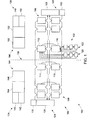
Fig. 1 is a schematic block diagram of an exemplary redundant sensing system. -
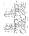
Fig. 2 is a schematic diagram of an exemplary digital redundant sensing system that is one embodiment of the sensing system shown inFig. 1 . -
Fig. 3 is a schematic diagram of one embodiment of an analog redundant sensing system that is another embodiment of the sensing system shown inFig. 1 . -
Fig. 4 is a schematic diagram of an alternative embodiment of the analog redundant sensing system shown inFig. 3 . -
Fig. 5 is a schematic diagram of another alternative embodiment of the analog redundant sensing system shown inFig. 3 . -
Fig. 6 is a flowchart that illustrates an exemplary method for performing a self-test of the redundant sensing system shown inFig. 1 . - Exemplary embodiments of systems, methods, and apparatus for use in redundant optical-sensor-based arc flash detection systems are described hereinabove. These embodiments facilitate reducing the possibility of a false positive reading within an arc flash detection system. For example, these embodiments reduce the number of failure modes that can cause a false indication that an entire arc flash detection system is working as intended. Moreover, these embodiments improve the availability of the arc flash detection system because faulty sensors, hubs, and/or controllers may be repaired and/or replaced while the system continues to monitor power distribution equipment. The embodiments described herein provide an arc flash detection system that includes a network of optical sensors that cover all potential flash points within a line-up of switchgear. These sensors communicate with hubs that perform sensor diagnostics and reduce the input/output (I/O) requirements to redundant controllers used to activate arc containment devices.
-
Fig. 1 is a schematic block diagram of an exemplaryredundant sensing system 100 as one embodiment of the invention, for use in detecting and mitigating arc flash events. In the exemplary embodiment ofFig. 1 ,sensing system 100 includes a plurality oflight sensor devices 102, each of which is positioned within a compartment of a stack ofswitchgear 104. Moreover,sensing system 100 includes a plurality ofhubs 106, including a first set ofhubs 108 and a second set of hubs 110. For example, first set ofhubs 108 includesfirst hub 112 andsecond hub 114, and second set of hubs 110 includes athird hub 116 that forms a redundant hub pair withfirst hub 112, and afourth hub 118 that forms a redundant hub pair withsecond hub 114. Eachhub 106 is positioned within a stack ofswitchgear 104 and is coupled to and configured for two-way communication with eachlight sensor device 102 positioned in thesame stack 104. For example,first hub 112 is coupled to afirst portion 120 oflight sensor devices 102. Similarly,third hub 116 is coupled to asecond portion 122 oflight sensor devices 102. - In addition,
sensing system 100 includes a plurality ofcontrollers 124 including afirst controller 126 and asecond controller 128. Eachcontroller 124 is coupled to eachhub 106 to facilitate communication redundancy. Eachcontroller 124 is coupled to or, alternatively includes, a power supply that supplies power, such as low-voltage DC power, tohubs 106. For example,first controller 126 includes or is coupled to afirst power supply 130 that supplies power to first set ofhubs 108, andsecond controller 128 includes or is coupled to asecond power supply 132 that supplies power to second set of hubs 110. - In the exemplary embodiment of
Fig. 1 ,sensing system 100 is coupled to power distribution equipment withinstacks 104. For example,Fig. 1 illustrates two stacks of switchgear in a main-tie-main configuration, including afirst stack 134 and asecond stack 136, separated by ashipping split 138.First stack 134 includesfirst controller 126, a portion of first set ofhubs 108, and a portion of second set of hubs 110. In addition,first stack 134 includes a first arcflash containment device 140, a firstmain circuit breaker 142, one or more firstfeeder circuit breakers 144, and atie circuit breaker 146 that selectively connectsfirst stack 134 andsecond stack 136.Second stack 136 includessecond controller 128, a portion of first set ofhubs 108, and a portion of second set of hubs 110. Moreover,second stack 136 includes a second arcflash containment device 148, a secondmain circuit breaker 150, and one or more secondfeeder circuit breakers 152. -
Fig. 2 is a schematic diagram of an exemplary digital redundant sensing system 200 that is one embodiment of sensing system 100 (shown inFig. 1 ). In the exemplary embodiment ofFig. 2 , eachlight sensor device 202 includes alight sensor 204 and alight source 206 that is positioned to cause a response bylight sensor 204. In some embodiments, eachlight sensor device 202 includesmultiple light sensors 204 to facilitate redundancy in detection of light related to an arc flash event.Light source 206 may be a light emitting diode (LED), an organic LED (OLED), a near infrared LED, or any other suitable device for emitting light or radiant energy.Light sensor 204 may be a photodetector, such as an optical detector, a photoresistor, a photodiode, a phototransister, an LED that is reverse-biased to detect light rather than to emit light, or any other suitable device for detecting light. Moreover, eachlight sensor device 202 includes power input ports 20 that receive power from ahub 210, a testsignal input port 212, a testsignal output port 214, and a sensorstatus output port 216. In the exemplary embodiment ofFig. 2 ,light sources 206 are serially connected, or "daisy chained," and are driven by a current received fromhub 210. In an alternative embodiment,light sources 206 may be separately coupled tohub 210 to enablehub 210 to individually controllight sources 206. - Each
hub 210 includes a plurality offirst input ports 218 that couple tolight sensors 204 to receive a sensor status. Moreover, eachhub 210 includes asecond input port 220 that receives a hub status from a paired redundancy hub. For example, afirst hub 222 includessecond input port 220 for receiving a hub status signal from asecond hub 224. Eachhub 210 also includes a plurality offirst output ports 226 for use in transmitting a paired hub status signal to one or more controllers (not shown inFig. 2 ). In addition, eachhub 210 includes asecond output port 228 that transmits a hub status to a paired redundancy hub. For example,first hub 222 includessecond output port 228 for transmitting a hub status signal tosecond input port 220 ofsecond hub 224.Second output port 228 is coupled to arelay 230 that is open during normal operation. Moreover, eachhub 210 includes a plurality of third output ports 232 that output power tolight sensor device 202 and also output a test signal that activateslight source 204 for use in testinglight sensor device 202. - Furthermore, each
hub 210 includes a plurality of current todigital comparators 234 that receive a sensor status fromlight sensor 204. The sensor status signal is a current having one of two levels. A lower current level is associated with a "sensor ready" status oflight sensor 204, and an upper current level is associated with a "light detected" status oflight sensor 204. Moreover, ifcomparators 234 detect a non-functioninglight sensor 204comparators 234 do not receive any sensor status signal. - Each
hub 210 also includes aprocessor 236 that determines the hub status and transmits the hub status to the paired hub.Processor 236 also determines the paired hub status and transmits a paired hub status signal to one or more controllers. The paired hub status signal represents a status of the paired ofredundant hubs 210 and is based on a hub status of eachhub 210. The hub status of eachhub 210 is based on the sensor status of eachlight sensor device 202 coupled tohub 210, and results of internal tests performed byhub 210. For example, whenfirst hub 222 detects no errors during its internal self-tests and detects no errors or sensor failures inlight sensor devices 202,processor 236 causes a relay coil ofrelay 230 to close, which results in a positive hub status signal to be sent tosecond hub 224. Ifprocessor 236 detects an error or loss of power,processor 236 causes the relay coil ofrelay 230 to remain open, which is detected bysecond hub 224.Second hub 224 then transmits a paired hub status signal to the controllers via one offirst output ports 226, wherein the paired hub status signal indicates a need for maintenance onfirst hub 222. However, if bothfirst hub 222 andsecond hub 224 detect an error or loss of power, both first andsecond hubs first output ports 226. Eachhub 210 is configured to transmit one of three signals to the controllers, including a first status signal that indicates to the controllers that no errors or loss of power have been detected, a second status signal that indicates that an error or loss of power was detected within a paired hub, and a third status signal that indicates that an error or loss of power has been detected in both hubs. Each possible signal is associated with a correspondingfirst output port 226.Processor 236 determines the signal to send to the controllers, and activates a field-effect transistor (FET) 238, which pulls an associated line to a low level. -
Fig. 3 is a schematic diagram of one embodiment of an analogredundant sensing system 300, for use in detecting and mitigating arc flash events. In the exemplary embodiment ofFig. 3 ,sensing system 300 includes a plurality oflight sensor devices 302 that each includes afuse 304, alinear regulator 306, atimer 308, alight source 310, and redundantlight sensors 312. Moreover, eachlight sensor device 302 includes an op-amp 314 that is coupled to a correspondinglight sensor 312 and a voltage-to-current converter 316 that is coupled to a corresponding op-amp 314. In addition, eachlight sensor device 302 includes afirst input port 318 that receives power from ahub 320, and asecond input port 322 that receives a sensor test command fromhub 320. Eachlight sensor device 302 also includes afirst output port 324 and asecond output port 326 that each transmit a sensor status signal tohub 320. Specifically,first output port 324 transmits a first sensor status signal associated with a first light sensor andsecond output port 326 transmits a second sensor status signal associated with a second light sensor. - Moreover, in the exemplary embodiment of
Fig. 3 ,sensing system 300 includes a plurality ofhubs 320, including afirst hub 328 and asecond hub 330. Furthermore, eachhub 320 is positioned within separate switchgear stacks. For example,first hub 328 is positioned to detect and mitigate arc flash events in afirst stack 332, andsecond hub 330 is positioned to detect and mitigate arc flash events in asecond stack 334. Eachhub 320 includes a plurality offirst input ports 336 that couple tolight sensors 312 to receive a sensor status. More specifically, eachhub 320 includes a respectivefirst input port 336 for each offirst output port 324 andsecond output port 326 oflight sensor device 302. Moreover, eachhub 320 includes asecond input port 338 that receives a hub status from a paired redundancy hub. For example,first hub 328 includessecond input port 338 for receiving a hub status signal from second 330. Eachhub 320 also includes a plurality offirst output ports 340 for use in transmitting a paired hub status signal to one or more controllers (not shown inFig. 3 ). In addition, eachhub 320 includes asecond output port 342 that transmits a hub status to a paired redundancy hub. For example,first hub 328 includessecond output port 342 for transmitting a hub status signal tosecond input port 338 ofsecond hub 330.Second output port 342 is coupled to tworelays 344 that are open during normal operation, but when closed indicate a normal operation status. Moreover, eachhub 320 includes a plurality ofthird output ports 346 that output power tolight sensor device 302 and also output a test signal that activateslight source 310 for use in testinglight sensor device 302. - Furthermore, each
hub 320 includes a plurality ofresistors 348 that receive a sensor status signal fromlight sensor 312. The sensor status signal is a current having one of two levels. A lower current level is associated with a "sensor ready" status oflight sensor 312, and an upper current level is associated with a "light detected" status oflight sensor 312. Moreover,resistors 348 detect a non-functioninglight sensor 312 ifresistors 348 do not receive any sensor status signal.Resistors 348 convert the sensor status signal into a voltage representative of the sensor status. For example, a lower voltage level is generated by the lower current level and is associated with the "sensor ready" status oflight sensor 312, and an upper voltage level is generated by the upper current level and is associated with the "light detected" status oflight sensor 312. - Each
hub 320 also includes aprocessor 350 that determines the hub status and transmits the hub status to the paired hub.Processor 350 also determines the paired hub status and transmits a paired hub status signal to the controllers. The paired hub status signal represents a status of the paired ofredundant hubs 320 and is based on a hub status of eachhub 320. The hub status of eachhub 320 is based on the sensor status of eachlight sensor device 302 coupled tohub 320, and results of internal tests performed byhub 320. For example, whenfirst hub 328 detects no errors during its internal self-tests and detects no errors or sensor failures inlight sensor devices 302,processor 350 causes a respective relay coil of eachrelay 344 to close, which results in a positive hub status signal to be sent tosecond hub 330. Ifprocessor 350 detects an error or loss of power,processor 350 causes the respective relay coil of eachrelay 344 to remain open, which is detected bysecond hub 330.Second hub 330 then transmits a paired hub status signal to the controllers via one offirst output ports 340, wherein the paired hub status signal indicates a need for maintenance onfirst hub 328. However, if bothfirst hub 328 andsecond hub 330 detect an error or loss of power, both first andsecond hubs first output ports 340. Eachhub 320 is configured to transmit one of three signals to the controllers, including a first status signal that indicates to the controllers that no errors or loss of power have been detected, a second status signal that indicates that an error or loss of power was detected within a paired hub, and a third status signal that indicates that an error or loss of power has been detected in both hubs. Each possible signal is associated with a correspondingfirst output port 340.Processor 350 determines the signal to send to the controllers, and activates a field-effect transistor (FET) 352, which pulls an associated line to a low level. In the exemplary embodiment ofFig. 3 ,processor 350 includes a plurality of analog-to-digital (A/D) converters (not shown). -
Fig. 4 is a schematic diagram of an alternative analogredundant sensing system 400, for use in detecting and mitigating arc flash events. The embodiment ofFig. 4 is similar to the embodiment ofFig. 3 , in thatsensing system 300 includes a plurality oflight sensor devices 302 and a plurality ofhubs 320. Moreover, eachhub 320 is positioned within separate switchgear stacks. For example,first hub 328 is positioned to detect and mitigate arc flash events in afirst stack 332, andsecond hub 330 is positioned to detect and mitigate arc flash events in asecond stack 334. - However,
sensing system 400 does not include a redundant connection betweenlight sensor devices 302 andhubs 320. Moreover, eachhub 320 is configured to transmit one of two signals to one or more controllers (not shown inFig. 4 ), including a first status signal that indicates to the controllers that no errors or loss of power have been detected, and a second status signal that indicates that an error or loss of power was detected within a paired hub. -
Fig. 5 is a schematic diagram of another alternative analogredundant sensing system 500, for use in detecting and mitigating arc flash events. The embodiment ofFig. 5 is similar to the embodiment ofFig. 4 , in thatsensing system 500 includes a plurality oflight sensor devices 302 and a plurality ofhubs 320. However, each switchgear stack includes bothfirst hub 328 andsecond hub 330 andlight sensor devices 302 coupled to each. Accordingly,sensing system 500 enables a fully redundant approach to detecting and mitigating arc flash events. -
Fig. 6 is aflowchart 600 illustrating an exemplary method for performing a self-test of a redundant sensing system, such as any of the redundant sensing systems shown inFigs. 1-5 . For simplicity, the operations described herein will refer to digital redundant sensing system 200 (shown inFig. 2 ) except to distinguish between digital and analog functionality, at which time the operations described herein will refer instead to, or in addition to, analog redundant sensing system 300 (shown inFig. 3 ). - In the exemplary embodiment of
Fig. 6 , eachhub 210 activates 602 alight source 206 within eachlight sensor device 202. For example, eachhub 210 transmits an activation signal to eachlight source 206 via third output port 232. In response to the activation signal, eachlight source 206 emits light toward a correspondinglight sensor 204.Light sensor 204 detects the light and transmits a sensor status signal tohub 210 at a specified current level. For example, a lower current level is associated with a "sensor ready" status oflight sensor 204, and an upper current level is associated with a "light detected" status oflight sensor 204. Moreover, a non-functioninglight sensor 204 does not transmit any sensor status signal, which is detected byhub 210. Eachhub 210 receives 604 the sensor status signal fromlight sensors 204 and determines 606 the sensor status of eachlight sensor device 202. In the digital embodiment ofFig. 2 , eachhub 210 includes current todigital comparators 234 that receive the sensor status signal fromlight sensor 204 and determines the sensor status according to the current level. In the analog embodiment ofFigs. 3-5 , eachhub 320 includesresistors 348 that convert the sensor status signal to a voltage, which is then converted into a digital value by a plurality of analog-to-digital (A/D) converters for use byprocessor 350 in determining the sensor status of eachlight sensor device 302. - Moreover, in the exemplary embodiment of
Fig. 6 , eachhub 210 determines 608 a hub status based on the sensor status of eachlight sensor device 202 and based on results of one or more internal tests.Processor 236 in eachhub 210 determines the hub status and transmits 610 the hub status to the paired hub.Processor 236 also receives 612 a hub status signal from the paired hub and determines 614 the paired hub status.Processor 236 then transmits 616 a paired hub status signal to one or more controllers 124 (shown inFig. 1 ). The paired hub status signal represents a status of the paired ofredundant hubs 210 and is based on a hub status of eachhub 210. The hub status of eachhub 210 is based on the sensor status of eachlight sensor device 202 coupled tohub 210, and results of internal tests performed byhub 210. - Exemplary embodiments of systems, methods, and apparatus for use in a redundant sensor and hub scheme for an arc flash prevention and mitigation system are described above in detail. The systems, methods, and apparatus are not limited to the specific embodiments described herein but, rather, operations of the methods and/or components of the system and/or apparatus may be utilized independently and separately from other operations and/or components described herein. Further, the described operations and/or components may also be defined in, or used in combination with, other systems, methods, and/or apparatus, and are not limited to practice with only the systems, methods, and storage media as described herein.
- A controller, such as those described herein, includes at least one processor or processing unit and a system memory. The controller typically has at least some form of computer readable media. By way of example and not limitation, computer readable media include computer storage media and communication media. Computer storage media include volatile and nonvolatile, removable and non-removable media implemented in any method or technology for storage of information such as computer readable instructions, data structures, program modules, or other data. Communication media typically embody computer readable instructions, data structures, program modules, or other data in a modulated data signal such as a carrier wave or other transport mechanism and include any information delivery media. Those skilled in the art are familiar with the modulated data signal, which has one or more of its characteristics set or changed in such a manner as to encode information in the signal. Combinations of any of the above are also included within the scope of computer readable media.
- Although the present invention is described in connection with an exemplary power distribution system environment, embodiments of the invention are operational with numerous other general purpose or special purpose power distribution system environments or configurations. The power distribution system environment is not intended to suggest any limitation as to the scope of use or functionality of any aspect of the invention. Moreover, the power distribution system environment should not be interpreted as having any dependency or requirement relating to any one or combination of components illustrated in the exemplary operating environment. Examples of well known power distribution systems, environments, and/or configurations that may be suitable for use with aspects of the invention include, but are not limited to, personal computers, server computers, handheld or laptop devices, multiprocessor systems, microprocessor-based systems, set top boxes, programmable consumer electronics, mobile telephones, network PCs, minicomputers, mainframe computers, distributed computing environments that include any of the above systems or devices, and the like.
- The order of execution or performance of the operations in the embodiments of the invention illustrated and described herein is not essential, unless otherwise specified. That is, the operations may be performed in any order, unless otherwise specified, and embodiments of the invention may include additional or fewer operations than those disclosed herein. For example, it is contemplated that executing or performing a particular operation before, contemporaneously with, or after another operation is within the scope of aspects of the invention.
- In some embodiments, the term "processor" refers generally to any programmable system including systems and microcontrollers, reduced instruction set circuits (RISC), application specific integrated circuits (ASIC), programmable logic circuits, and any other circuit or processor capable of executing the functions described herein. The above examples are exemplary only, and thus are not intended to limit in any way the definition and/or meaning of the term processor.
- When introducing elements of aspects of the invention or embodiments thereof, the articles "a," "an," "the," and "said" are intended to mean that there are one or more of the elements. The terms "comprising," including," and "having" are intended to be inclusive and mean that there may be additional elements other than the listed elements.
- This written description uses examples to disclose the invention, including the best mode, and also to enable any person skilled in the art to practice the invention, including making and using any devices or systems and performing any incorporated methods. The patentable scope of the invention is defined by the claims, and may include other examples that occur to those skilled in the art. Such other examples are intended to be within the scope of the claims if they have structural elements that do not differ from the literal language of the claims, or if they include equivalent structural elements with insubstantial differences from the literal language of the claims.
Various aspects and embodiments of the present invention are defined by the following numbered clauses: - 1. A hub for use with a circuit protection system, said hub comprising:
- a first input port configured to communicatively couple to at least one sensor device, wherein the at least one sensor device includes a light source and at least one light sensor;
- a first output port configured to communicatively couple to at least one controller; and
- a processor communicatively coupled to said first input port and to said first output port, said processor configured to:
- receive a sensor status signal from the at least one light sensor via said first input port in response to a test pulse emitted by the light source; and
- transmit a hub status signal to the at least one controller via said first output port based at least in part on the sensor status signal.
- 2. A hub in accordance with
Clause 1, wherein the at least one sensor device includes a plurality of sensor devices, and wherein said first input port comprises a plurality of first input ports each configured to communicatively couple to a respective sensor device of the plurality of sensor devices. - 3. A hub in accordance with
Clause 1 orClause 2, wherein said processor is further configured to:- activate a respective light source of each of the plurality of sensor devices to test a corresponding light sensor; and
- receive a sensor status signal from each of the plurality of sensor devices.
- 4. A hub in accordance with any preceding Clause, wherein said processor is further configured to receive a current representative of the sensor status signal from each of the plurality of sensor devices and to determine a sensor status for each of the plurality of sensor devices based on the current.
- 5. A hub in accordance with any preceding Clause, wherein said processor is further configured to determine the hub status based at least in part on the sensor status of each of the plurality of sensor devices.
- 6. A hub in accordance with any preceding Clause, wherein said processor is further configured to determine a hub status of said hub based at least in part on the sensor status signal and an operation status of said hub, and wherein the hub status signal is representative of the hub status.
- 7. A hub in accordance with any preceding Clause, wherein said hub further comprises a second output port configured to communicatively couple to a paired redundant hub, and wherein said processor is further configured to transmit the hub status to the paired redundant hub via said second output port.
- 8. A hub in accordance with any preceding Clause, wherein said hub further comprises a second input port configured to communicatively couple to a paired redundant hub, and wherein said processor further configured to receive a hub status of the paired redundant hub via said second input port.
- 9. A redundant light sensing system comprising:
- a plurality of sensor devices each comprising a light source and at least one light sensor;
- at least one controller configured to activate a circuit protection device;
and - at least one hub communicatively coupled to said plurality of sensor devices and to said at least one controller, said at least one hub configured to:
- receive a sensor status signal from said at least one light sensor of each of said plurality of sensor devices;
- transmit a hub status signal to said at least one controller, wherein the hub status signal is based at least in part on the sensor status signal;
- receive an arc flash detection signal from one of said plurality of sensor devices; and
- transmit the arc flash detection signal to said at least one controller for use in activating the circuit protection device.
- 10. A redundant light sensing system in accordance with Clause 9, wherein said at least one hub comprises a first hub and a second hub, said first hub communicatively coupled to a first plurality of sensor devices and said second hub communicatively coupled to a second plurality of sensor devices.
- 11. A redundant light sensing system in accordance with Clause 9 or
Clause 10, wherein said first hub is configured to:- receive a sensor status signal from said at least one light sensor of each of said first plurality of sensor devices; and
- transmit a first hub status signal to said at least one controller and to said second hub, wherein the first hub status signal is based at least in part on the sensor status signal.
- 12. A redundant light sensing system in accordance with any of Clauses 9 to 11, wherein said second hub is configured to:
- receive a sensor status signal from said at least one light sensor of each of said second plurality of sensor devices; and
- transmit a second hub status signal to said at least one controller and to said first hub, wherein the second hub status signal is based at least in part on the sensor status signal.
- 13. A redundant light sensing system in accordance with any of Clauses 9 to 12, wherein said at least one hub is further configured to determine a hub status of said at least one hub, and wherein the hub status signal is representative of the hub status and is based at least in part on the sensor status signal and an operation status of said at least one hub.
- 14. A redundant light sensing system in accordance with any of Clauses 9 to 13, wherein said at least one controller comprises a first controller and a second controller, each of said first controller and said second controller communicatively coupled to said at least one hub and to the circuit protection device, each of said first controller and said second controller configured to receive the hub status signal and the arc detection signal from said at least one hub and to activate the circuit protection device based on the arc detection signal.
- 15. A method comprising:
- activating a light source within each of a plurality of sensor devices;
- receiving a sensor status signal from each of the plurality of sensor devices, wherein the sensor status signal is representative of whether a respective light sensor in each of the plurality of sensor devices detects a test pulse emitted by a corresponding light sensor;
- determining a sensor status of each of the plurality of sensor devices based one the sensor status signals;
- determining a hub status based at least in part on the sensor status of each of the plurality of sensor devices; and
- transmitting a hub status signal representative of the hub status to a redundancy hub and to at least one controller.
- 16. A method in accordance with Clause 15, wherein activating a light source within each of a plurality of sensor devices comprises:
- using a first hub to activate a light source of each of a first plurality of sensor devices to test a corresponding light sensor;
- receiving, by the first hub, a sensor status signal from each of the first plurality of sensor devices;
- using a second hub to activate a light source of each of a second plurality of sensor devices to test a corresponding light sensor; and
- receiving, by the second hub, a sensor status signal from each of the second plurality of sensor devices.
- 17. A method in accordance with Clause 15 or Clause 16, wherein determining a sensor status comprises receiving a current representative of the sensor status signal from each of the plurality of sensor devices and determining a sensor status for each of the plurality of sensor devices based on the current.
- 18. A method in accordance with any of Clauses 15 to 17, wherein determining a hub status comprises determining the hub status based on the sensor status signal of each of the plurality of sensor devices and an operation status of the hub.
- 19. A method in accordance with any of Clauses 15 to 18, further comprising receiving an arc flash detection signal from one of the plurality of sensor devices.
- 20. A method in accordance with any of Clauses 15 to 19, further comprising transmitting the arc flash detection signal to the at least one controller for use in activating a circuit protection device.
Claims (15)
- A hub (106) for use with a circuit protection system, said hub (106) comprising:a first input port (218) configured to communicatively couple to at least one sensor device (102), wherein the at least one sensor device (102) includes a light source (206) and at least one light sensor (204);a first output port (226) configured to communicatively couple to at least one controller (124); anda processor (236) communicatively coupled to said first input port (218) and to said first output port (226), said processor (236) configured to:receive a sensor status signal from the at least one light sensor (204) via said first input port (218) in response to a test pulse emitted by the light source (206); andtransmit a hub status signal to the at least one controller (124) via said first output port (226) based at least in part on the sensor status signal.
- A hub (106) in accordance with Claim 1, wherein the at least one sensor device (102) includes a plurality of sensor devices (102), and wherein said first input port (226) comprises a plurality of first input ports (226) each configured to communicatively couple to a respective sensor device (102) of the plurality of sensor devices (102).
- A hub (106) in accordance with Claim 1 or Claim 2, wherein said processor (236) is further configured to:activate a respective light source (206) of each of the plurality of sensor devices (102) to test a corresponding light sensor (204); andreceive a sensor status signal from each of the plurality of sensor devices (102).
- A hub (106) in accordance with any preceding Claim, wherein said processor (236) is further configured to receive a current representative of the sensor status signal from each of the plurality of sensor devices (102) and to determine a sensor status for each of the plurality of sensor devices (102) based on the current.
- A hub (106) in accordance with any preceding Claim, wherein said processor (236) is further configured to determine the hub status based at least in part on the sensor status of each of the plurality of sensor devices (102).
- A hub (106) in accordance with any preceding Claim, wherein said processor (236) is further configured to determine a hub status of said hub (106) based at least in part on the sensor status signal and an operation status of said hub (106), and wherein the hub status signal is representative of the hub status.
- A hub (106) in accordance with any preceding Claim, wherein said hub (106) further comprises a second output port (228) configured to communicatively couple to a paired redundant hub (106), and wherein said processor (236) is further configured to transmit the hub status to the paired redundant hub (106) via said second output port (228).
- A hub (106) in accordance with any preceding Claim, wherein said hub (106) further comprises a second input port (220) configured to communicatively couple to a paired redundant hub (106), and wherein said processor (236) further configured to receive a hub status of the paired redundant hub (106) via said second input port (220).
- A redundant light sensing system (100) comprising:a plurality of sensor devices (102) each comprising a light source (206) and at least one light sensor (204);at least one controller (124) configured to activate a circuit protection device; andat least one hub (106) communicatively coupled to said plurality of sensor devices (102) and to said at least one controller (124), said at least one hub (106) configured to:receive a sensor status signal from said at least one light sensor (204) of each of said plurality of sensor devices (102);transmit a hub status signal to said at least one controller (124), wherein the hub status signal is based at least in part on the sensor status signal;receive an arc flash detection signal from one of said plurality of sensor devices (102); andtransmit the arc flash detection signal to said at least one controller (124) for use in activating the circuit protection device.
- A redundant light sensing system in accordance with Claim 9, wherein said at least one hub (106) comprises a first hub (112) and a second hub (114), said first hub (112) communicatively coupled to a first plurality of sensor devices (120) and said second hub (114) communicatively coupled to a second plurality of sensor devices (122).
- A method comprising:activating a light source within each of a plurality of sensor devices;receiving a sensor status signal from each of the plurality of sensor devices, wherein the sensor status signal is representative of whether a respective light sensor in each of the plurality of sensor devices detects a test pulse emitted by a corresponding light sensor;determining a sensor status of each of the plurality of sensor devices based one the sensor status signals;determining a hub status based at least in part on the sensor status of each of the plurality of sensor devices; andtransmitting a hub status signal representative of the hub status to a redundancy hub and to at least one controller.
- A method in accordance with Claim 11, wherein activating a light source within each of a plurality of sensor devices comprises:using a first hub to activate a light source of each of a first plurality of sensor devices to test a corresponding light sensor;receiving, by the first hub, a sensor status signal from each of the first plurality of sensor devices;using a second hub to activate a light source of each of a second plurality of sensor devices to test a corresponding light sensor; andreceiving, by the second hub, a sensor status signal from each of the second plurality of sensor devices.
- A method in accordance with Claim 11 or Claim 12, wherein determining a sensor status comprises receiving a current representative of the sensor status signal from each of the plurality of sensor devices and determining a sensor status for each of the plurality of sensor devices based on the current.
- A method in accordance with any of Claims 11 to 13, wherein determining a hub status comprises determining the hub status based on the sensor status signal of each of the plurality of sensor devices and an operation status of the hub.
- A method in accordance with any of Claims 11 to 14, further comprising receiving an arc flash detection signal from one of the plurality of sensor devices.
Applications Claiming Priority (1)
| Application Number | Priority Date | Filing Date | Title |
|---|---|---|---|
| US12/872,734 US8335063B2 (en) | 2010-08-31 | 2010-08-31 | Redundant systems, methods, and apparatus for use in arc flash prevention systems |
Publications (3)
| Publication Number | Publication Date |
|---|---|
| EP2424060A2 true EP2424060A2 (en) | 2012-02-29 |
| EP2424060A3 EP2424060A3 (en) | 2014-07-09 |
| EP2424060B1 EP2424060B1 (en) | 2020-02-12 |
Family
ID=44741210
Family Applications (1)
| Application Number | Title | Priority Date | Filing Date |
|---|---|---|---|
| EP11178937.6A Active EP2424060B1 (en) | 2010-08-31 | 2011-08-25 | Redundant systems, methods, and apparatus for use in arc flash prevention systems |
Country Status (5)
| Country | Link |
|---|---|
| US (1) | US8335063B2 (en) |
| EP (1) | EP2424060B1 (en) |
| JP (1) | JP2012053043A (en) |
| KR (1) | KR101806560B1 (en) |
| CN (1) | CN102437564B (en) |
Families Citing this family (2)
| Publication number | Priority date | Publication date | Assignee | Title |
|---|---|---|---|---|
| US11411382B1 (en) | 2022-01-26 | 2022-08-09 | Arc Suppression Technologies | Arc flash suppressor, system, and method |
| CN115102142B (en) * | 2022-07-01 | 2026-03-20 | 帝森克罗德集团有限公司 | An arc flash protection system for power plants |
Family Cites Families (18)
| Publication number | Priority date | Publication date | Assignee | Title |
|---|---|---|---|---|
| JPH0738011B2 (en) * | 1988-05-16 | 1995-04-26 | 株式会社日立製作所 | Abnormality diagnosis system for high-voltage power equipment |
| JPH02119510A (en) * | 1988-10-26 | 1990-05-07 | Toshiba Corp | Compressed gas insulated switchgear |
| GB9021484D0 (en) * | 1990-10-03 | 1990-11-14 | Univ Strathclyde | Gas insulated substations |
| DE4331992A1 (en) * | 1993-09-21 | 1995-03-23 | Kloeckner Moeller Gmbh | Cell-like switching installation which is protected against internal arcs, for distribution of electrical energy |
| DE4345170A1 (en) * | 1993-09-21 | 1995-03-23 | Kloeckner Moeller Gmbh | Arc fault protection device for switchgear for the distribution of electrical energy |
| JP2000065887A (en) * | 1998-08-20 | 2000-03-03 | Takaoka Electric Mfg Co Ltd | Fault location system for power equipment |
| JP3907998B2 (en) * | 2001-02-09 | 2007-04-18 | 株式会社東芝 | Substation protection control system |
| US7747356B2 (en) | 2002-02-25 | 2010-06-29 | General Electric Company | Integrated protection, monitoring, and control system |
| US7259565B2 (en) | 2003-09-15 | 2007-08-21 | General Electric Company | Testing an electrical switchgear system |
| US7012382B2 (en) | 2004-04-30 | 2006-03-14 | Tak Meng Cheang | Light emitting diode based light system with a redundant light source |
| CN1695999B (en) * | 2004-05-13 | 2011-02-09 | 通用电气公司 | Method and appatus of monitoring and controlling alarm system |
| US8952291B2 (en) * | 2005-09-15 | 2015-02-10 | Lincoln Global, Inc. | System and method for controlling a hybrid welding process |
| US7382272B2 (en) * | 2005-10-19 | 2008-06-03 | Schweitzer Engineering Laboratories, Inc. | System, a tool and method for communicating with a faulted circuit indicator using a remote display |
| US7729808B2 (en) * | 2006-03-10 | 2010-06-01 | Edsa Micro Corporation | System for comparing real-time data and modeling engine data to predict arc flash events |
| US20080142486A1 (en) * | 2006-12-19 | 2008-06-19 | Nataniel Barbosa Vicente | Circuit breaker with adjustable arc-flash protection and wireless sensor and method of use |
| DE102007004943A1 (en) * | 2007-01-26 | 2008-07-31 | Abb Ag | System and method for controlling one or more switchgear |
| FR2914122B1 (en) * | 2007-03-23 | 2009-08-28 | Airbus France Sas | DEVICE AND METHOD FOR PROTECTING AN ELECTRONIC SYSTEM AGAINST ELECTRIC ARCS. |
| US8803069B2 (en) * | 2008-09-19 | 2014-08-12 | Schweitzer Engineering Laboratories, Inc. | Electro-optical radiation collector for arc flash detection |
-
2010
- 2010-08-31 US US12/872,734 patent/US8335063B2/en active Active
-
2011
- 2011-08-25 EP EP11178937.6A patent/EP2424060B1/en active Active
- 2011-08-30 JP JP2011186664A patent/JP2012053043A/en active Pending
- 2011-08-31 CN CN201110268665.7A patent/CN102437564B/en active Active
- 2011-08-31 KR KR1020110087626A patent/KR101806560B1/en active Active
Non-Patent Citations (1)
| Title |
|---|
| None |
Also Published As
| Publication number | Publication date |
|---|---|
| KR20120022070A (en) | 2012-03-09 |
| US20120053743A1 (en) | 2012-03-01 |
| EP2424060A3 (en) | 2014-07-09 |
| KR101806560B1 (en) | 2017-12-07 |
| CN102437564A (en) | 2012-05-02 |
| JP2012053043A (en) | 2012-03-15 |
| CN102437564B (en) | 2016-03-23 |
| US8335063B2 (en) | 2012-12-18 |
| EP2424060B1 (en) | 2020-02-12 |
Similar Documents
| Publication | Publication Date | Title |
|---|---|---|
| US20140192458A1 (en) | Power distribution systems and methods of operating a power distribution system including arc flash detection | |
| US8575916B2 (en) | Method, system, and apparatus for detecting an arc event using breaker status | |
| US8649146B2 (en) | Capacitance check and current monitoring circuit for use with a circuit protection device | |
| US9325167B2 (en) | Method, system, and apparatus for providing arc flash mitigation | |
| US20160202306A1 (en) | Device for detecting open phase of connection line of standby transformer in nuclear power plant by using rogowski coil | |
| EP2466319B1 (en) | Capacitance check and voltage monitoring circuit for use with a circuit protection device | |
| EP2541572A1 (en) | Method and apparatus for monitoring of a tap changer | |
| CN108462144A (en) | Using communication network test to the method and power distribution system of the response of electric situation | |
| US9722408B2 (en) | ARC-free capacitor trip device | |
| CN103683181B (en) | The method of distribution system and operation distribution system | |
| CN108462157A (en) | Power distribution system and the method for executing Earth Fault Detection wherein | |
| CN108462141B (en) | Power distribution system and method of performing zone selective interlocking therein | |
| US8335063B2 (en) | Redundant systems, methods, and apparatus for use in arc flash prevention systems | |
| JP6509029B2 (en) | Distribution board | |
| US20150244163A1 (en) | Current and voltage module and methods of monitoring current and voltage in power distribution systems | |
| US10230232B2 (en) | Automated ground fault interrupt tester | |
| US9281677B2 (en) | Method for protecting an electrical energy distribution box | |
| CN207381953U (en) | Arc, earth leakage | |
| KR20120007920U (en) | A monitoring apparatus for DC electric souce of circuit breaker | |
| JP2017195716A (en) | Power transmission line protection system | |
| CN103066577B (en) | A kind of excision of contact line circuit intelligent fault equipment, system and method thereof | |
| US20230187924A1 (en) | Power supply system, ground fault detection method and program | |
| Aprahamian et al. | A POTENTIAL APPLICATION OF ARC FAULT CIRCUIT INTERRUPTERS: IN SHIP ELECTRIC SYSTEMS. |
Legal Events
| Date | Code | Title | Description |
|---|---|---|---|
| AK | Designated contracting states |
Kind code of ref document: A2 Designated state(s): AL AT BE BG CH CY CZ DE DK EE ES FI FR GB GR HR HU IE IS IT LI LT LU LV MC MK MT NL NO PL PT RO RS SE SI SK SM TR |
|
| AX | Request for extension of the european patent |
Extension state: BA ME |
|
| PUAI | Public reference made under article 153(3) epc to a published international application that has entered the european phase |
Free format text: ORIGINAL CODE: 0009012 |
|
| PUAL | Search report despatched |
Free format text: ORIGINAL CODE: 0009013 |
|
| RIC1 | Information provided on ipc code assigned before grant |
Ipc: H02H 1/00 20060101AFI20140520BHEP Ipc: H02H 3/05 20060101ALN20140520BHEP Ipc: H02H 3/04 20060101ALI20140520BHEP |
|
| AK | Designated contracting states |
Kind code of ref document: A3 Designated state(s): AL AT BE BG CH CY CZ DE DK EE ES FI FR GB GR HR HU IE IS IT LI LT LU LV MC MK MT NL NO PL PT RO RS SE SI SK SM TR |
|
| AX | Request for extension of the european patent |
Extension state: BA ME |
|
| 17P | Request for examination filed |
Effective date: 20150109 |
|
| RBV | Designated contracting states (corrected) |
Designated state(s): AL AT BE BG CH CY CZ DE DK EE ES FI FR GB GR HR HU IE IS IT LI LT LU LV MC MK MT NL NO PL PT RO RS SE SI SK SM TR |
|
| 17Q | First examination report despatched |
Effective date: 20160628 |
|
| STAA | Information on the status of an ep patent application or granted ep patent |
Free format text: STATUS: EXAMINATION IS IN PROGRESS |
|
| RAP1 | Party data changed (applicant data changed or rights of an application transferred) |
Owner name: ABB SCHWEIZ AG |
|
| GRAP | Despatch of communication of intention to grant a patent |
Free format text: ORIGINAL CODE: EPIDOSNIGR1 |
|
| STAA | Information on the status of an ep patent application or granted ep patent |
Free format text: STATUS: GRANT OF PATENT IS INTENDED |
|
| RIC1 | Information provided on ipc code assigned before grant |
Ipc: H02H 3/05 20060101ALN20191023BHEP Ipc: H02H 7/22 20060101ALI20191023BHEP Ipc: H02H 3/04 20060101ALI20191023BHEP Ipc: H02H 1/00 20060101AFI20191023BHEP |
|
| INTG | Intention to grant announced |
Effective date: 20191107 |
|
| RIN1 | Information on inventor provided before grant (corrected) |
Inventor name: HOOKER, JOHN KENNETH Inventor name: LAFOND, MICHAEL PAUL Inventor name: MASON JR., HENRY HALL Inventor name: BARDOLPH, MEGAN DALENE |
|
| GRAS | Grant fee paid |
Free format text: ORIGINAL CODE: EPIDOSNIGR3 |
|
| GRAA | (expected) grant |
Free format text: ORIGINAL CODE: 0009210 |
|
| STAA | Information on the status of an ep patent application or granted ep patent |
Free format text: STATUS: THE PATENT HAS BEEN GRANTED |
|
| AK | Designated contracting states |
Kind code of ref document: B1 Designated state(s): AL AT BE BG CH CY CZ DE DK EE ES FI FR GB GR HR HU IE IS IT LI LT LU LV MC MK MT NL NO PL PT RO RS SE SI SK SM TR |
|
| REG | Reference to a national code |
Ref country code: GB Ref legal event code: FG4D |
|
| REG | Reference to a national code |
Ref country code: CH Ref legal event code: EP |
|
| REG | Reference to a national code |
Ref country code: AT Ref legal event code: REF Ref document number: 1233360 Country of ref document: AT Kind code of ref document: T Effective date: 20200215 |
|
| REG | Reference to a national code |
Ref country code: IE Ref legal event code: FG4D |
|
| REG | Reference to a national code |
Ref country code: DE Ref legal event code: R096 Ref document number: 602011064896 Country of ref document: DE |
|
| PG25 | Lapsed in a contracting state [announced via postgrant information from national office to epo] |
Ref country code: RS Free format text: LAPSE BECAUSE OF FAILURE TO SUBMIT A TRANSLATION OF THE DESCRIPTION OR TO PAY THE FEE WITHIN THE PRESCRIBED TIME-LIMIT Effective date: 20200212 Ref country code: NO Free format text: LAPSE BECAUSE OF FAILURE TO SUBMIT A TRANSLATION OF THE DESCRIPTION OR TO PAY THE FEE WITHIN THE PRESCRIBED TIME-LIMIT Effective date: 20200512 Ref country code: FI Free format text: LAPSE BECAUSE OF FAILURE TO SUBMIT A TRANSLATION OF THE DESCRIPTION OR TO PAY THE FEE WITHIN THE PRESCRIBED TIME-LIMIT Effective date: 20200212 |
|
| REG | Reference to a national code |
Ref country code: LT Ref legal event code: MG4D |
|
| REG | Reference to a national code |
Ref country code: NL Ref legal event code: MP Effective date: 20200212 |
|
| PG25 | Lapsed in a contracting state [announced via postgrant information from national office to epo] |
Ref country code: SE Free format text: LAPSE BECAUSE OF FAILURE TO SUBMIT A TRANSLATION OF THE DESCRIPTION OR TO PAY THE FEE WITHIN THE PRESCRIBED TIME-LIMIT Effective date: 20200212 Ref country code: LV Free format text: LAPSE BECAUSE OF FAILURE TO SUBMIT A TRANSLATION OF THE DESCRIPTION OR TO PAY THE FEE WITHIN THE PRESCRIBED TIME-LIMIT Effective date: 20200212 Ref country code: HR Free format text: LAPSE BECAUSE OF FAILURE TO SUBMIT A TRANSLATION OF THE DESCRIPTION OR TO PAY THE FEE WITHIN THE PRESCRIBED TIME-LIMIT Effective date: 20200212 Ref country code: IS Free format text: LAPSE BECAUSE OF FAILURE TO SUBMIT A TRANSLATION OF THE DESCRIPTION OR TO PAY THE FEE WITHIN THE PRESCRIBED TIME-LIMIT Effective date: 20200612 Ref country code: GR Free format text: LAPSE BECAUSE OF FAILURE TO SUBMIT A TRANSLATION OF THE DESCRIPTION OR TO PAY THE FEE WITHIN THE PRESCRIBED TIME-LIMIT Effective date: 20200513 Ref country code: BG Free format text: LAPSE BECAUSE OF FAILURE TO SUBMIT A TRANSLATION OF THE DESCRIPTION OR TO PAY THE FEE WITHIN THE PRESCRIBED TIME-LIMIT Effective date: 20200512 |
|
| PG25 | Lapsed in a contracting state [announced via postgrant information from national office to epo] |
Ref country code: NL Free format text: LAPSE BECAUSE OF FAILURE TO SUBMIT A TRANSLATION OF THE DESCRIPTION OR TO PAY THE FEE WITHIN THE PRESCRIBED TIME-LIMIT Effective date: 20200212 |
|
| PG25 | Lapsed in a contracting state [announced via postgrant information from national office to epo] |
Ref country code: RO Free format text: LAPSE BECAUSE OF FAILURE TO SUBMIT A TRANSLATION OF THE DESCRIPTION OR TO PAY THE FEE WITHIN THE PRESCRIBED TIME-LIMIT Effective date: 20200212 Ref country code: SK Free format text: LAPSE BECAUSE OF FAILURE TO SUBMIT A TRANSLATION OF THE DESCRIPTION OR TO PAY THE FEE WITHIN THE PRESCRIBED TIME-LIMIT Effective date: 20200212 Ref country code: CZ Free format text: LAPSE BECAUSE OF FAILURE TO SUBMIT A TRANSLATION OF THE DESCRIPTION OR TO PAY THE FEE WITHIN THE PRESCRIBED TIME-LIMIT Effective date: 20200212 Ref country code: SM Free format text: LAPSE BECAUSE OF FAILURE TO SUBMIT A TRANSLATION OF THE DESCRIPTION OR TO PAY THE FEE WITHIN THE PRESCRIBED TIME-LIMIT Effective date: 20200212 Ref country code: EE Free format text: LAPSE BECAUSE OF FAILURE TO SUBMIT A TRANSLATION OF THE DESCRIPTION OR TO PAY THE FEE WITHIN THE PRESCRIBED TIME-LIMIT Effective date: 20200212 Ref country code: PT Free format text: LAPSE BECAUSE OF FAILURE TO SUBMIT A TRANSLATION OF THE DESCRIPTION OR TO PAY THE FEE WITHIN THE PRESCRIBED TIME-LIMIT Effective date: 20200705 Ref country code: ES Free format text: LAPSE BECAUSE OF FAILURE TO SUBMIT A TRANSLATION OF THE DESCRIPTION OR TO PAY THE FEE WITHIN THE PRESCRIBED TIME-LIMIT Effective date: 20200212 Ref country code: DK Free format text: LAPSE BECAUSE OF FAILURE TO SUBMIT A TRANSLATION OF THE DESCRIPTION OR TO PAY THE FEE WITHIN THE PRESCRIBED TIME-LIMIT Effective date: 20200212 Ref country code: LT Free format text: LAPSE BECAUSE OF FAILURE TO SUBMIT A TRANSLATION OF THE DESCRIPTION OR TO PAY THE FEE WITHIN THE PRESCRIBED TIME-LIMIT Effective date: 20200212 |
|
| REG | Reference to a national code |
Ref country code: DE Ref legal event code: R097 Ref document number: 602011064896 Country of ref document: DE |
|
| REG | Reference to a national code |
Ref country code: AT Ref legal event code: MK05 Ref document number: 1233360 Country of ref document: AT Kind code of ref document: T Effective date: 20200212 |
|
| PLBE | No opposition filed within time limit |
Free format text: ORIGINAL CODE: 0009261 |
|
| STAA | Information on the status of an ep patent application or granted ep patent |
Free format text: STATUS: NO OPPOSITION FILED WITHIN TIME LIMIT |
|
| 26N | No opposition filed |
Effective date: 20201113 |
|
| PG25 | Lapsed in a contracting state [announced via postgrant information from national office to epo] |
Ref country code: AT Free format text: LAPSE BECAUSE OF FAILURE TO SUBMIT A TRANSLATION OF THE DESCRIPTION OR TO PAY THE FEE WITHIN THE PRESCRIBED TIME-LIMIT Effective date: 20200212 |
|
| PG25 | Lapsed in a contracting state [announced via postgrant information from national office to epo] |
Ref country code: SI Free format text: LAPSE BECAUSE OF FAILURE TO SUBMIT A TRANSLATION OF THE DESCRIPTION OR TO PAY THE FEE WITHIN THE PRESCRIBED TIME-LIMIT Effective date: 20200212 Ref country code: PL Free format text: LAPSE BECAUSE OF FAILURE TO SUBMIT A TRANSLATION OF THE DESCRIPTION OR TO PAY THE FEE WITHIN THE PRESCRIBED TIME-LIMIT Effective date: 20200212 |
|
| PG25 | Lapsed in a contracting state [announced via postgrant information from national office to epo] |
Ref country code: MC Free format text: LAPSE BECAUSE OF FAILURE TO SUBMIT A TRANSLATION OF THE DESCRIPTION OR TO PAY THE FEE WITHIN THE PRESCRIBED TIME-LIMIT Effective date: 20200212 |
|
| REG | Reference to a national code |
Ref country code: CH Ref legal event code: PL |
|
| GBPC | Gb: european patent ceased through non-payment of renewal fee |
Effective date: 20200825 |
|
| PG25 | Lapsed in a contracting state [announced via postgrant information from national office to epo] |
Ref country code: LI Free format text: LAPSE BECAUSE OF NON-PAYMENT OF DUE FEES Effective date: 20200831 Ref country code: CH Free format text: LAPSE BECAUSE OF NON-PAYMENT OF DUE FEES Effective date: 20200831 Ref country code: LU Free format text: LAPSE BECAUSE OF NON-PAYMENT OF DUE FEES Effective date: 20200825 |
|
| REG | Reference to a national code |
Ref country code: BE Ref legal event code: MM Effective date: 20200831 |
|
| PG25 | Lapsed in a contracting state [announced via postgrant information from national office to epo] |
Ref country code: GB Free format text: LAPSE BECAUSE OF NON-PAYMENT OF DUE FEES Effective date: 20200825 Ref country code: IE Free format text: LAPSE BECAUSE OF NON-PAYMENT OF DUE FEES Effective date: 20200825 Ref country code: BE Free format text: LAPSE BECAUSE OF NON-PAYMENT OF DUE FEES Effective date: 20200831 |
|
| PG25 | Lapsed in a contracting state [announced via postgrant information from national office to epo] |
Ref country code: TR Free format text: LAPSE BECAUSE OF FAILURE TO SUBMIT A TRANSLATION OF THE DESCRIPTION OR TO PAY THE FEE WITHIN THE PRESCRIBED TIME-LIMIT Effective date: 20200212 Ref country code: MT Free format text: LAPSE BECAUSE OF FAILURE TO SUBMIT A TRANSLATION OF THE DESCRIPTION OR TO PAY THE FEE WITHIN THE PRESCRIBED TIME-LIMIT Effective date: 20200212 Ref country code: CY Free format text: LAPSE BECAUSE OF FAILURE TO SUBMIT A TRANSLATION OF THE DESCRIPTION OR TO PAY THE FEE WITHIN THE PRESCRIBED TIME-LIMIT Effective date: 20200212 |
|
| PG25 | Lapsed in a contracting state [announced via postgrant information from national office to epo] |
Ref country code: MK Free format text: LAPSE BECAUSE OF FAILURE TO SUBMIT A TRANSLATION OF THE DESCRIPTION OR TO PAY THE FEE WITHIN THE PRESCRIBED TIME-LIMIT Effective date: 20200212 Ref country code: AL Free format text: LAPSE BECAUSE OF FAILURE TO SUBMIT A TRANSLATION OF THE DESCRIPTION OR TO PAY THE FEE WITHIN THE PRESCRIBED TIME-LIMIT Effective date: 20200212 |
|
| REG | Reference to a national code |
Ref country code: DE Ref legal event code: R081 Ref document number: 602011064896 Country of ref document: DE Owner name: ABB S.P.A., IT Free format text: FORMER OWNER: ABB SCHWEIZ AG, BADEN, CH |
|
| PGFP | Annual fee paid to national office [announced via postgrant information from national office to epo] |
Ref country code: DE Payment date: 20250820 Year of fee payment: 15 |
|
| PGFP | Annual fee paid to national office [announced via postgrant information from national office to epo] |
Ref country code: IT Payment date: 20250825 Year of fee payment: 15 |
|
| PGFP | Annual fee paid to national office [announced via postgrant information from national office to epo] |
Ref country code: FR Payment date: 20250829 Year of fee payment: 15 |