EP2423999A1 - Battery pack - Google Patents
Battery pack Download PDFInfo
- Publication number
- EP2423999A1 EP2423999A1 EP10767146A EP10767146A EP2423999A1 EP 2423999 A1 EP2423999 A1 EP 2423999A1 EP 10767146 A EP10767146 A EP 10767146A EP 10767146 A EP10767146 A EP 10767146A EP 2423999 A1 EP2423999 A1 EP 2423999A1
- Authority
- EP
- European Patent Office
- Prior art keywords
- members
- portions
- battery
- pillar
- supporting
- Prior art date
- Legal status (The legal status is an assumption and is not a legal conclusion. Google has not performed a legal analysis and makes no representation as to the accuracy of the status listed.)
- Withdrawn
Links
Images








Classifications
-
- H—ELECTRICITY
- H01—ELECTRIC ELEMENTS
- H01M—PROCESSES OR MEANS, e.g. BATTERIES, FOR THE DIRECT CONVERSION OF CHEMICAL ENERGY INTO ELECTRICAL ENERGY
- H01M50/00—Constructional details or processes of manufacture of the non-active parts of electrochemical cells other than fuel cells, e.g. hybrid cells
- H01M50/20—Mountings; Secondary casings or frames; Racks, modules or packs; Suspension devices; Shock absorbers; Transport or carrying devices; Holders
-
- H—ELECTRICITY
- H01—ELECTRIC ELEMENTS
- H01M—PROCESSES OR MEANS, e.g. BATTERIES, FOR THE DIRECT CONVERSION OF CHEMICAL ENERGY INTO ELECTRICAL ENERGY
- H01M50/00—Constructional details or processes of manufacture of the non-active parts of electrochemical cells other than fuel cells, e.g. hybrid cells
- H01M50/20—Mountings; Secondary casings or frames; Racks, modules or packs; Suspension devices; Shock absorbers; Transport or carrying devices; Holders
- H01M50/204—Racks, modules or packs for multiple batteries or multiple cells
-
- H—ELECTRICITY
- H01—ELECTRIC ELEMENTS
- H01M—PROCESSES OR MEANS, e.g. BATTERIES, FOR THE DIRECT CONVERSION OF CHEMICAL ENERGY INTO ELECTRICAL ENERGY
- H01M10/00—Secondary cells; Manufacture thereof
- H01M10/60—Heating or cooling; Temperature control
- H01M10/62—Heating or cooling; Temperature control specially adapted for specific applications
- H01M10/625—Vehicles
-
- H—ELECTRICITY
- H01—ELECTRIC ELEMENTS
- H01M—PROCESSES OR MEANS, e.g. BATTERIES, FOR THE DIRECT CONVERSION OF CHEMICAL ENERGY INTO ELECTRICAL ENERGY
- H01M50/00—Constructional details or processes of manufacture of the non-active parts of electrochemical cells other than fuel cells, e.g. hybrid cells
- H01M50/20—Mountings; Secondary casings or frames; Racks, modules or packs; Suspension devices; Shock absorbers; Transport or carrying devices; Holders
- H01M50/289—Mountings; Secondary casings or frames; Racks, modules or packs; Suspension devices; Shock absorbers; Transport or carrying devices; Holders characterised by spacing elements or positioning means within frames, racks or packs
- H01M50/291—Mountings; Secondary casings or frames; Racks, modules or packs; Suspension devices; Shock absorbers; Transport or carrying devices; Holders characterised by spacing elements or positioning means within frames, racks or packs characterised by their shape
-
- H—ELECTRICITY
- H01—ELECTRIC ELEMENTS
- H01M—PROCESSES OR MEANS, e.g. BATTERIES, FOR THE DIRECT CONVERSION OF CHEMICAL ENERGY INTO ELECTRICAL ENERGY
- H01M2220/00—Batteries for particular applications
- H01M2220/20—Batteries in motive systems, e.g. vehicle, ship, plane
-
- H—ELECTRICITY
- H01—ELECTRIC ELEMENTS
- H01M—PROCESSES OR MEANS, e.g. BATTERIES, FOR THE DIRECT CONVERSION OF CHEMICAL ENERGY INTO ELECTRICAL ENERGY
- H01M6/00—Primary cells; Manufacture thereof
- H01M6/42—Grouping of primary cells into batteries
-
- Y—GENERAL TAGGING OF NEW TECHNOLOGICAL DEVELOPMENTS; GENERAL TAGGING OF CROSS-SECTIONAL TECHNOLOGIES SPANNING OVER SEVERAL SECTIONS OF THE IPC; TECHNICAL SUBJECTS COVERED BY FORMER USPC CROSS-REFERENCE ART COLLECTIONS [XRACs] AND DIGESTS
- Y02—TECHNOLOGIES OR APPLICATIONS FOR MITIGATION OR ADAPTATION AGAINST CLIMATE CHANGE
- Y02E—REDUCTION OF GREENHOUSE GAS [GHG] EMISSIONS, RELATED TO ENERGY GENERATION, TRANSMISSION OR DISTRIBUTION
- Y02E60/00—Enabling technologies; Technologies with a potential or indirect contribution to GHG emissions mitigation
- Y02E60/10—Energy storage using batteries
Definitions
- the present invention relates to a battery pack.
- Patent Literature 1 has disclosed a technology of forming a battery pack by: forming a battery module by arranging multiple batteries; and arranging such battery modules. Particularly, such a battery pack is installed in electric cars for use as drive sources for their motors.
- Patent Literature 1 Japanese Patent Unexamined Publication No. 2007-165164
- the conventional battery pack has a problem that the overall volume of the battery pack becomes large if a side from which various brackets and the like protrude is different from a side on which accessories such as a battery controller are disposed.
- An object of the present invention is to provide a battery pack reduced in overall volume.
- a battery pack of the present invention is characterized by including: paired supporting members disposed with a predetermined interval in between; a battery module disposed between the supporting members; and a stack member supporting the battery module by linking the supporting members to each other, and characterized in that: an extending portion protruding from the battery module is formed by extending an end portion of the stack member in an extending direction of the stack member; the supporting member and the extending portion of the stack member are connected to each other by a supporting bracket; and accessories are attached to at least a side surface on a side where the extending portion of the stack member is disposed, the side surface being one of side surfaces of the battery pack which are provided with the paired supporting members.
- the battery module of the present invention is not limited to one formed from multiple batteries, but includes one formed of a single battery.
- a first embodiment and a second embodiment as a battery pack to be installed in an electric car being an example of a vehicle.
- the battery pack can be installed in other vehicles such as a hybrid car including a motor and an engine.
- descriptions are given below of a battery pack in which battery modules each obtained by arranging multiple batteries in a thickness direction of the batteries are vertically stacked.
- the present invention can be applied to a battery pack in which individual batteries are vertically stacked.
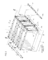
- Fig. 1 is a perspective view showing a battery pack of a first embodiment of the present invention.
- a battery pack 1 of the embodiment includes: three battery modules 3, 5, 7 stacked vertically; and accessories 12 attached to side portions of the respective battery modules 3, 5, 7.
- the battery pack 1 in an on-vehicle state is disposed in a way that a vehicle front side, a vehicle rear side, and a vehicle width direction are as shown by their respective arrows in Fig. 1 .
- Three battery modules include: the upper battery module 3 disposed in the uppermost tier: a center battery module 5 disposed in the middle in a height direction; and the lower battery module 7 disposed in the lowermost tier.
- These battery modules 3, 5, 7 are connected to each other by elongated supporting plates 11 extending in a vertical direction and supporting brackets 51, which will be described later.
- the aforementioned accessories 12 include, specifically, a battery controller (for example, a lithium-ion battery controller) 13, wire harnesses 14, an attachment plate 16 to which to attach the battery controller 13, and the like.
- a battery controller for example, a lithium-ion battery controller
- wire harnesses 14 an attachment plate 16 to which to attach the battery controller 13, and the like.
- Fig. 2 is a perspective view showing a process of assembling the battery pack.
- the supporting plates 11 are fastened by bolts to a pallet jig 31 placed on a floor surface.
- End plates 36 being parts of supporting members 35 are fastened to the supporting plates 11 by bolts.
- Each supporting member 35 is formed from a corresponding one of the end plates 36 and reinforcement member 37.
- the reinforcement members 37 are joined to the end plate 36.
- bent portions 37b, 37c bent and extending in a lateral direction are provided to the lower end of each reinforcement member 37, and a bent portion 37a bent and extending in the lateral direction (the substantially horizontal direction) is provided to the upper end of the reinforcement member 37.
- the bent portions 37b, 37c are fastened to a corresponding one of the supporting plates 11 by bolts.
- each of stack members 43 in a longitudinal direction are extended to form extending portions 43a which overhang (protrude) from the battery modules 3, 5, 7.
- the stack members 43 support the battery modules 3, 5, 7 by use of bolts 45 and connecting members, which are not illustrated.
- the paired supporting members 35 formed from the end plate 36 and the reinforcement members 37 are provided, respectively, on the two endmost side surfaces of the battery module 3 in the vehicle width direction.
- the accessories 12 (see Fig. 1 ) are provided on at least a side surface situated on a side where the extending portions 43a of the stack members 43 are disposed, which is one of the side surfaces on which the supporting members 35 are disposed.
- the supporting members 35 are provided respectively on both sides in the vehicle width direction, and the extending portions 43a of the stack members 43 are provided on both sides.
- the attachment plate 16, the battery controller 13, and the wire harnesses 14 connected to the battery controller 13, which constitute the accessories 12 are disposed on the side surfaces of both supporting members 35, 35.
- each of the battery modules 3, 5, 7 is formed by arranging the plate-shaped batteries 9 side by side in the thickness direction. Multiple terminals (not shown) are provided on the upper surfaces of the batteries 9. Moreover, as shown in Fig. 2 , each of the supporting brackets 51 is integrally formed from an upper surface 51a and a side surface 51b formed by being bent in a direction orthogonal to the upper surface 51a, and has an almost L-shape in a side view.
- the supporting brackets 51 are attached, from below, to the extending portions 43a of the stack members 43 and the bent portions 37a of the reinforcement members 37.
- a corner portion which is shaped almost like the letter L in the side view, is formed, in an upper end portion of the side surface of each supporting member 35, by the extending portions 43a of the corresponding stack member 43 and the bent portion 37a of the corresponding reinforcement member 37.
- the upper surfaces 51a of the supporting brackets 51 are pressed against the lower sides of the extending portions 43a and the lower sides of the bent portions 37a, and the supporting brackets 51 are fastened to the extending portions 43a and the bent portions 37a by screwing bolts from above.
- the supporting brackets 51 are attached, from below, to the extending portions 43a of the stack members 43 and the bent potions 37a of the reinforcement members 37 with the supporting brackets 51 matched to the upper end corner portions of the supporting members 35.
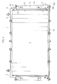
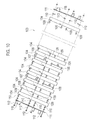
- Fig. 4 is a plan view showing the battery pack shown in Fig. 1 , which is viewed from above.
- a length L1 by which the extending portion 43a of the stack member 43 protrudes from the upper battery module 3 is set larger than a length L2 by which the battery controller 13 being one of the accessories 12 protrudes from the upper battery module 3.
- L1 is defined as a length of the extending portion 43a in the extending direction, between an edge 3a of the upper battery module 3 which extends in the thickness direction of the batteries 9 (in an extending direction of the extending portion 43a) and an edge 43b of the extending portion 43a of the stack member 43.
- L2 is defined as a length in the extending direction of the extending portion 43a between the edge 3a of the upper battery module 3 which extends in the thickness direction of the batteries 9 and a side surface 13a of the battery controller 13.
- L1 and L2 are set to satisfy a relationship of L1>L2. Note that the protruding length of each wire harnesses 14, which is not illustrated, is also set smaller than L1.
- the accessories 12 are attached to the side surfaces of the supporting members 35 disposed on the sides provided with the extending portions 43a of the stack members 43 as described above, the overall volume of the battery pack 1 can be reduced.
- the accessories 12 are disposed on a side surface which is not on the sides on which the extending portions 43a of the stack members 43 are disposed, the volume is increased by the extending portions 43a on the side on which the extending portions 43a are disposed and the volume is increased by the accessories 12 on the side provided with the accessories 12.
- disposing the accessories 12 on the side surfaces on the sides on which the extending portions 43a are disposed allows the overall volume of the battery pack 1 to be reduced.
- the extending portions 43a of the stack members 43 can protect the accessories 12.
- the bent portions 37a of the reinforcement members 37 and the extending portions 43a of the stack members 43 do not protrude toward the terminals of the batteries 9.
- wires are easily connected to the terminals, and the entire battery pack 1 can be made compact.
- the accessories 12 can be attached to the side surface of the battery pack 1 which is provided with reinforcement members 37, and the side surface is effectively used.
- FR indicates frontward in a vehicle frontward-rearward direction
- UP indicates upward in a vehicle upward-downward direction
- a battery pack 102 of the embodiment is installed in an electric car, and supplies electricity to a driving motor of the electric car.
- the battery pack 102 of the embodiment can be installed in other vehicle such as a hybrid car including a motor and an engine.
- the battery pack 102 installed in an electric car includes multiple battery modules 103 vertically stacked, and a controller (not shown).
- the battery pack of the embodiment includes three battery modules 103, and these battery modules 103 are connected together in series, for example, by use of connection members, which are not illustrated.
- each of the battery modules 103 includes: multiple batteries 104 arranged in a row and; a frame 105 holding the multiple batteries 104.
- the batteries 104 are connected together in series by use of connection members, which are not illustrated.
- each of the batteries 104 is formed in a rectangular plate shape, and insertion holes 104a are formed in the respective four corners of the battery 104 in a manner that makes the insertion holes 104a penetrate the battery 104 in a plate-thickness direction.
- the battery 104 is a secondary battery such as a lithium ion secondary battery, a nickel hydrogen secondary battery, or a nickel cadmium secondary battery.
- the multiple batteries 104 are arranged side by side in a row (in the thickness direction of the batteries 104).
- First connection members 107 serving as connection members, second connection members 108 serving as connection members, and spacers Ia9 are provided between the batteries 104.
- One of the first connection members 107 and one of the second connection members 108 are disposed together between each adjacent two of the batteries 104.
- the multiple first connection members 107 are arranged in the direction of the row of the batteries 104 with intervals in between
- the multiple second connection members 108 are arranged in the direction of the row of the batteries 104 with intervals in between.
- the first connection member 107 includes: a plate portion 107a to be interposed between each two adjacent batteries 104; paired cylinder portions 107b penetrating the plate portion 107a; paired attachment portions 107c formed by being bent from the plate portion 107a; and bolt portions 107d fixed to the respective attachment portions 107c.
- the first connection member 107 is disposed between each two adjacent batteries 104 with end portions of the cylinder portions 107b fitted into the insertion holes 104a of the battery 104 on the front side, and with the plate portion 107a interposed between the adjacent batteries 104.
- the second connection member 108 includes: a plate portion 108a to be interposed between each two adjacent batteries 104; paired cylinder portions 108b penetrating the plate portion 108a; an attachment portion 108c formed by being bent from the plate portion 108a; and a bolt portion 108d fixed to the attachment portion 108c.
- the second connection member 108 is disposed between each two adjacent batteries 104 with end portions of the cylinder portions 108b fitted into the insertion holes 104a of the battery 104 on the rear side, and with the plate portion 108a interposed between the adjacent batteries 104.
- the first connection member 107 and the second connection member 108 thus disposed between each two adjacent batteries 104 cause the adjacent batteries 104 to be positioned to each other, and form a gap between the adjacent batteries 104.
- the spacers 109 are disposed in a space between the each two adjacent batteries 104 in which neither the first connection member 107 nor the second connection member 108 is disposed.
- Each of the spacers 109 includes a cylinder portion 109a. and a flange portion 109b provided on the circumferential surface of the cylinder portion 109a.
- the spacers 109 are disposed between each two adjacent batteries 104, matching the insertion holes 104a of the batteries 104.
- Each spacer 109 is disposed between each two adjacent batteries 104 with the end portion of the cylinder portion 109a fitted into the corresponding insertion hole 104a of the battery 104, and with the flange portion 109b interposed between the adjacent batteries 104.
- the spacers 109 thus disposed cause the adjacent batteries 104 to be positioned to each other, and form a gap between the adjacent batteries 104.
- different spacers 110 are disposed between each endmost battery 104 and its corresponding end plate 111.
- the frame 105 includes: paired end plates 111 sandwiching the stacked multiple batteries 104; multiple through-bolts 112 inserted in the end plates 111 and the multiple batteries 104 in the direction of the row of the batteries 104; stack members 43 situated on the outer side of the batteries 104, and extending in the direction of the row of the batteries 104; and a stack plate 114.
- the through-bolts 112 are provided, matching the respective insertion holes 104a of each battery 104.
- the two through-bolts 112 on the rear side are respectively inserted in the cylinder portions 107b of the first connection members 107 and the cylinder portions 109a of the spacers 109 as well.
- the two through-bolts on the front side are inserted in the cylinder portions 108b of the second connection member 108 and the cylinder portions 109a of the spacers 109 as well.
- nuts 115 are screwed to the through-bolts 102, respectively.
- the through-bolts 112 support the multiple batteries 104, and the paired end plates 111 hold the multiple batteries 104 between the end plates 111. While in this state, the two through bolts 112 on the rear side are connected to the first connection members 107, and the two through bolts 112 on the front side are connected to the second connection members 108.
- each of the stack members 43 is formed in a band plate-like shape, and is provided on the rear side of the battery module 103.
- An extending portion 43 a is formed in each of the two end portions of the stack member 43.
- multiple first insertion holes are formed in the stack members 43, matching the first connection members 107, respectively.
- the bolt portions 107d of the first connection members 107 are inserted in the first insertion holes, and nuts 116 are screwed to the bolt portions 107d, respectively.
- the first connection members 107 are fixed to the stack members 43.
- the first connection members 107 link together the stack member 43 and the through-bolts 112 on the front side.
- a center line CL in Fig. 7 indicates a center position of the battery module 103 in the direction of the row (longitudinal direction).
- the stack plate 114 is formed in a band plate-like shape, and is provided on the front side of the battery module 103.
- An attachment portion 114a is formed in each of the two end portions of the stack plate 114 by bending.
- An insertion hole 114b is formed in the attachment portion 114a, penetrating the attachment portion 114a in the direction of the row of the batteries 104.
- a nut 114c is fixed to the attachment portion 114a. The nut 114c communicates with the insertion hole 114b.
- multiple second insertion holes (not shown) are formed in the stack plate 114, matching the second connection members 108, respectively.
- the bolt portions 108d of the second connection members 108 are inserted in the second insertion holes, and nuts 117 are screwed to the bolt portions 108d, respectively.
- the second connection members 108 are fixed to the stack plate 114.
- the second connection members 108 link the stack plate 114 and the through-bolts 112 on the front side to each other.
- a reinforcement plate 118 is fixed to each of the end plates 111.
- a first attachment portion 118a is formed in a stack member 43-side end portion of the reinforcement plate 118 by bending, and paired second attachment portions 118b are formed in a stack plate 114-side end portion of the reinforcement plate 118 by bending.
- An engagement hole 118c serving as a first engaging portion is formed in each of the second attachment portions 118b.
- an interval between the connection members (the first connection members 107 and the second connection members 108) adjacent to each other in the direction of the row of the batteries 104 becomes smaller from the ends toward the center in the direction of the row of the batteries 104 of the battery module 103.
- Each of the battery modules 103 is supported at both end portions 103b in the direction of the row of the batteries 104. Moreover, each of the stack members 43, the stack plate 114, and the through-bolts 112 are supported at both ends thereof. In this state, a space is provided between each two battery modules 103 vertically adjacent to each other, and a space is provided below the lowermost battery module 103.
- the batteries 104 are designed to be cooled by the air flowing through these spaces.
- a main frame which is not illustrated, includes first and second pillar members 121, 122 being paired pillar members provided in a manner that makes the first and second pillar members 121, 122 correspond to the respective end portions of the battery module 103 in the direction of the row, and the like, as well as is configured to be fixed to a vehicle body.
- the first and second pillar members 121, 122 each support the corresponding end portion of the battery module 103.
- the first pillar member 121 includes: a pillar main body 123 formed of a plate member; and multiple pin members 124 fixed to the pillar main body 123, and serving as second engagement portions.
- a tapered portion 124a having a circular truncated cone shape whose diameter becomes smaller toward the tip is formed in an end portion of each of the pin members 124.
- the tapered portion 124a is inserted in and is thus engaged with the corresponding one of the engagement holes 118c of the reinforcement members 118.
- the pin member 124 is specifically a screw Note that the tapered portion 124a may be formed integrally with the pin member 124, as shown in Fig. 13(c) .
- a separate tapered cap 224a may be fitted to an end of the pin member 224.
- the pillar main body 123 is formed of: a first flat plate portion 123a; a second flat plate portion 123b formed by being bent from a side edge of the first flat plate portion 123a; a third flat plate portion 123c formed by being bent from a side edge of the second flat plate portion 123b; and a fourth flat plate portion 123d formed by being bent from the third flat plate portion 123c. Accordingly, the pillar main body 123 has an almost W-shaped cross section.
- the pin members 124 are arranged with an interval between each two adjacent pin members 124 in the longitudinal direction of the first pillar member 121. Moreover, a pin member 126 different from the pin members 124 is also fixed to the first flat plate portion 123a.
- insertion holes 123e are formed with an interval between each two adjacent insertion holes 123e in the longitudinal direction of the pillar member 121
- insertion holes 123f are formed with an interval between the insertion holes 123f in the longitudinal direction of the pillar member 121.
- Each of the insertion holes 123f is positioned between the corresponding two adjacent insertion holes 123e, and one of the insertion holes 123f is provided with a nut 125.
- the nut 125 is fixed to the fourth flat plate portion 123d by welding or the like, and communicates with the one insertion hole 123f.
- the second pillar member 122 is basically the same as the first pillar member 121, and is formed to be right-left symmetrical with respect to the first pillar member.
- the second pillar member 122 includes: a pillar main body 128 formed of a plate member; and multiple pin members 129 fixed to the pillar main body 128, and serving as the second engagement portions.
- a tapered portion 129a whose diameter becomes smaller toward the tip is formed in an end portion of each of the pin members 129, as in the case of the pin members 124.
- the tapered portion 129a is engaged with the corresponding one of the engagement holes 118c of the reinforcement members 118 by being inserted in the engagement hole 118c.
- the pin member 129 is a screw.
- the tapered portion 129a may be formed integrally with the pin member 129.
- a separate tapered cap (not shown) may be fitted to an end of a pin member.
- the pillar main body 128 is formed of: a first flat plate portion 128a; a second flat plate portion 128b formed by being bent from a side edge of the first flat plate portion 128a; a third flat plate portion 128c formed by being bent from a side edge of the second flat plate portion 128b; and a fourth flat plate portion 128d formed by being bent from the third flat plate portion 128c, as well as has an almost W-shaped cross section.
- the pin members 129 are arranged with an interval between each two adjacent pin members 129 in the longitudinal direction of the second pillar member 122. Moreover, a pin member 130 different from the pin members 129 is also fixed to the first flat plate portion 128a.
- insertion holes 128e are formed with an interval between each two adjacent insertion holes 128e in the longitudinal direction of the pillar member 122
- insertion holes 128f are formed with an interval between the insertion holes 128f in the longitudinal direction of the pillar member 122.
- Each of the insertion holes 128f are positioned between the corresponding two adjacent insertion holes 128e.
- the second pillar member 122 is not provided with a nut which corresponds to the nut 125 of the first pillar member 121.
- the method of positioning the battery modules is a method of positioning the battery modules 103 and the first and second pillar members 121, 122 relative to one another, the battery modules 103 each including the multiple batteries 104 in a row, the first and second pillar members 121, 122 being the paired pillar members for supporting the end portions of the battery modules 103 in the direction of the row.
- the battery modules 103 and the first and second pillar members 121, 122 are designed to be capable of being positioned using a jig apparatus 200 shown in Fig. 15 .
- the jig apparatus 200 includes: a pallet 201; and bolts 204, 205 being turn prevention members for preventing the turn of pillar members 121, 122. Note that in the descriptions below, the lateral direction (right-left direction) and the longitudinal direction of the pallet 201 will be simply referred to as the lateral direction and the longitudinal direction, respectively.
- the pallet 201 includes: a base portion 201g shaped like a rectangular plate; and leg portions 201p formed integrally with the respective lower portions of the base portion 201g.
- paired supporting portions 201a, 201b extending in the longitudinal direction are formed respectively in both edge portions in the lateral direction, and a block portion 201c is formed between the paired supporting portions 201a, 201b.
- paired groove portions 201d, 201e are formed respectively in a portion between the supporting portion 201a and the block portion 201c, and in a portion between the supporting portion 201b and the block portion 201c.
- the groove portions 201d, 201e extend in the longitudinal direction, and are formed with an interval in between in the lateral direction.
- Multiple lateral groove portions 201f extending in the lateral direction are formed in the supporting portion 201a.
- Multiple lateral groove portions 201i extending in the lateral direction are formed in the supporting portion 201b.
- the lateral groove portions 201f are formed with an interval between each two adjacent lateral groove portions 201f in the longitudinal direction
- the lateral groove portions 201i are formed with an interval between each two adjacent lateral groove portions 201i in the longitudinal direction.
- multiple insertion holes 201h are formed in the supporting portion 201a.
- multiple insertion holes 201k, 201j are formed in the supporting portion 201b.
- the insertion holes 201h are formed with an interval in between in the longitudinal direction, and the insertion holes 201k, 201j are formed with an interval in between in the longitudinal direction.
- the insertion holes 201h penetrate the supporting portion 201a in the lateral direction, and the insertion holes 201k, 201j penetrate the supporting portion 201b in the lateral direction.
- the corresponding one of the bolts 204, 205 is inserted into each of the insertion holes 201h, 201k, 201j.
- reinforcement plates 201m are provided on the outer surface of each of the supporting portions 201a, 201b, and the insertion holes 201h, 201k, 201j are formed, respectively penetrating the reinforcement plates 201m as well.
- An upper surface 201r of the right supporting portion 201b functions as a slide support portion for slidably supporting the second pillar member 122 in a way that enables the adjustment of an interval between the first and second pillar members 121, 122 in the direction of the row of the batteries 104, and the adjustment of relative positions of the respective first and second pillar members 121, 122 in the direction orthogonal to the direction of the row of the batteries 104.
- Screw holes 201n are formed in both side portions of the block portion 201c, situated coaxial with the respective insertion holes 201h, 201k, 201j which are formed in the supporting portion 201a, 201b.
- the screw holes 201n are formed, extending in the lateral direction.
- the battery modules 103 are mounted on the pallet 201 with the first and second pillar members 121, 122 in between in such a way that: the direction of the row of the batteries 104 coincides with the lateral direction of the pallet 201; and the direction orthogonal to the direction of the row of the batteries 104 coincides with the longitudinal direction of the pallet 201.
- the first and second pillar members 121, 122 are assembled to the jig apparatus 200 (a pillar members assembling step).
- the first pillar member 121 is mounted on the one (left) supporting portion 201a, and the second pillar member 122 is mounted on the other (right) supporting portion 201b.
- the third flat plate portions 123c, 128c of the first and second pillar members 121, 122 are mounted on upper surfaces 201 q, 201r r of the supporting portions 201a, 201b, respectively; and the fourth flat plate portions 123d, 128d of the first and second pillar members 121, 122 are brought into contact with inner surfaces 201s (an inner surface of the supporting portion 201b is not shown) of the supporting portions 201a, 201b, respectively.
- the bolt 204 is inserted in the insertion hole 201h of the one (left) supporting portion 201a on a far side and in the insertion hole 123f of the first pillar member 121 on the far side. Subsequently, the bolt 204 is screwed to the nut 125, Subsequently, the bolt 205 is inserted in the insertion hole 201h of the supporting portion 201a on a near side and in the insertion hole 123f of the first pillar member 121 on the near side. Thereafter, the bolt 205 is screwed to the corresponding screw hole 201n. Thus, the first pillar member 121 is fixed to the pallet 201.
- the bolt 205 is inserted in the insertion hole 201j of the other (right) supporting portion 201b on the far side and in the insertion hole 128f of the second pillar member 122 on the far side. Subsequently, the bolt 205 is screwed to the corresponding screw hole 201n. Concurrently, the bolt 205 is inserted in the insertion hole 201k of the supporting portion 201b on the near side and in the insertion hole 128f of the second pillar member 122 on the near side. Thereafter, the bolt 205 is screwed to the corresponding screw hole 201n.
- the second pillar member 122 While in this state, the second pillar member 122 is supported by the upper surface 201r of the supporting portion 201b, movable in the longitudinal direction and the lateral direction. To be more specific, the second pillar member 122 is movable in a direction toward the first pillar member 121, which is the lateral direction.
- the second pillar member 122 is slidably supported by the upper surface 201r of the supporting portion 201b in a way that enables the adjustment of the interval between the first and second pillar members 121, 122 in the lateral direction (the direction of the row of the batteries 104), and the adjustment of the relative positions of the respective first and second pillar members 121, 122 in the longitudinal direction (the direction orthogonal to the direction of the row of the batteries 104) are adjustable.
- each of the insertion holes 123f 128f of the first and second pillar members 121, 122 is formed, larger than the diameter of a shaft portion of the bolts 205, and there is a backlash between each of the insertion holes 123f, 128f and their corresponding bolts 205. Accordingly, the insertion holes 128f allow the second pillar member 122 to move in the lateral direction (the direction of the row of the batteries 104) and in the longitudinal direction (the direction orthogonal to the direction of the row of the batteries 104), with the bolts 205 being inserted.
- the turn of the first pillar member 121 is prevented by the bolts 204, 205.
- the turn of the second pillar member 122 is prevented by the bolts 205.
- slingers 206 are fixed to the two respective end portions of the battery module 103 by bolts 207, 208.
- the slingers 206 are hooked to a crane (not shown), and the battery module 103 is moved to a position above the jig apparatus 200 by the crane. Then, as shown in Figs. 19 and 20 , the battery module 103 is lowered (moved) toward the first and second pillar members 121, 122 assembled to the jig apparatus 200. Thereafter, the pin members 124, 129 of the first and second pillar members 121, 122 are engaged with the insertion holes 118b of the battery module 103, and the first and second pillar members 121, 122 and the battery module 103 are positioned relative to one another (a relative positioning step). At this time, the tapered portions 129a of the pin members 129 are inserted into the insertion holes 118b while being in contact with the insertion holes 118b, and this causes the second pillar member 122 to be automatically positioned to the battery module 103.
- a bolt 210 is screwed to each of the nuts 114c of the extending portions 43a of the second supporting member 113 of the battery modules 103, and thus the extending portions 43a are fixed to the first and second pillar members 121, 122 (see Fig. 21 ).
- the bolts 210 can by screwed to the nuts 114c by inserting the bolts 210 into the lateral groove portions 201f. 201i.
- the slingers 206 are removed from the battery modules 103.
- Frame members other than the first and second pillar members 121, 122, as well as a control device and the like are attached to the battery modules 103.
- the battery pack 102 can be detached from the pallet 201 by removing the bolts 204, 205.
- the present invention is not limited to the embodiments describe above, and can employ other various embodiments within the scope not departing from the gist of the present invention.
- the slide support portion is not limited to the upper surface 201r of the other supporting portion 201b, and may be the upper surface 201 q of the one supporting portion 201a.
- the screw hole 201n is provided instead of the nut 125.
- the upper surface 201q slidably supports the first pillar member 121 in a way that enables the adjustment of the interval between the first and second pillar members 121, 122 in the lateral direction (the direction of the row of the batteries 104), and the adjustment of the relative positions of the respective first and second pillar members 121, 122 in the longitudinal direction (the direction orthogonal to the direction of the row of the batteries 104).
- the slide support portion may be formed of the upper surfaces 201q, 201r of the two respective supporting portions 201a, 201b. In other words, it suffices if the slide support portion supports at least one of the paired pillar members in a way that enables the adjustment of the interval between the paired pillar members in the direction of the row in the battery module, and the adjustment of the relative positions of the respective paired pillar member in the direction orthogonal to the direction of the row.
- the present invention makes it possible to reduce the overall volume of the battery pack, because the accessories are attached to the side surfaces of the supporting members disposed on the sides where the extending portions of the stack members.
- the accessories would be disposed on a side surface on a side different from the sides where the extending portions of the stack members are disposed, the volume would be increased by the extending portions on the side where the extending portions are disposed, while the volume would be increased by the accessories on the side where the accessories are provided. For this reason, disposing the accessories on the side surfaces on the sides where the extending portions are disposed makes it possible to reduce the overall volume of the battery pack.
Landscapes
- Chemical & Material Sciences (AREA)
- Chemical Kinetics & Catalysis (AREA)
- Electrochemistry (AREA)
- General Chemical & Material Sciences (AREA)
- Engineering & Computer Science (AREA)
- Manufacturing & Machinery (AREA)
- Battery Mounting, Suspending (AREA)
Abstract
Description
- The present invention relates to a battery pack.
-
Patent Literature 1, for example, has disclosed a technology of forming a battery pack by: forming a battery module by arranging multiple batteries; and arranging such battery modules. Particularly, such a battery pack is installed in electric cars for use as drive sources for their motors. - Patent Literature 1: Japanese Patent Unexamined Publication No.
2007-165164 - However, the conventional battery pack has a problem that the overall volume of the battery pack becomes large if a side from which various brackets and the like protrude is different from a side on which accessories such as a battery controller are disposed.
- An object of the present invention is to provide a battery pack reduced in overall volume.
- A battery pack of the present invention is characterized by including: paired supporting members disposed with a predetermined interval in between; a battery module disposed between the supporting members; and a stack member supporting the battery module by linking the supporting members to each other, and characterized in that: an extending portion protruding from the battery module is formed by extending an end portion of the stack member in an extending direction of the stack member; the supporting member and the extending portion of the stack member are connected to each other by a supporting bracket; and accessories are attached to at least a side surface on a side where the extending portion of the stack member is disposed, the side surface being one of side surfaces of the battery pack which are provided with the paired supporting members. Note that the battery module of the present invention is not limited to one formed from multiple batteries, but includes one formed of a single battery.
-
- [
Fig. 1] Fig. 1 is a perspective view showing a battery pack of a first embodiment of the present invention. - [
Fig. 2] Fig. 2 is a perspective view showing a process of assembling the battery pack of the first embodiment of the present invention. - [
Fig. 3] Fig. 3 is a perspective view showing the battery pack of the first embodiment of the present invention which is an assembled end product. - [
Fig. 4] Fig. 4 is a plan view of the battery pack ofFig. 1 which is viewed from above. - [
Fig. 5] Fig. 5 is perspective view showing a battery pack of a second embodiment of the present invention. - [
Fig. 6] Fig. 6 is a perspective view showing a battery module of the second embodiment of the present invention. - [
Fig. 7] Fig. 7 is a front view showing the battery module of the second embodiment of the present invention. - [
Fig. 8] Fig. 8 is a plan view showing the battery module of the second embodiment of the present invention. - [
Fig. 9] Fig. 9 is a side view showing the battery module of the second embodiment of the present invention. - [
Fig. 10] Fig. 10 is an exploded perspective view showing the battery module of the second embodiment of the present invention. - [
Fig. 11] Fig. 11 is an exploded perspective view showing a battery, and first and second connection members of the second embodiment of the present invention. - [
Fig. 12] Fig. 12 is an exploded perspective view showing the battery and spacers of the second embodiment of the present invention. - [
Fig. 13] Fig. 13 shows a first pillar member of the second embodiment of the present invention.Fig. 13(a) is a side view thereof,Fig. 13(b) is a front view thereof, andFigs. 13(c) and 13(d) are side views of pin members. - [
Fig. 14] Fig. 14 shows a second pillar member of the second embodiment of the present invention.Fig. 14(a) is a side view thereof, andFig. 14(b) is a front view thereof. - [
Fig. 15] Fig. 15 5 is a view showing a process of manufacturing the battery pack of the second embodiment of the present invention. - [
Fig. 16] Fig. 16 is another view showing a process of manufacturing the battery pack of the second embodiment of the present invention. - [
Fig. 17] Fig. 17 is another view showing a process of manufacturing the battery pack of the second embodiment of the present invention. - [
Fig. 18] Fig. 18 is another view showing a process of manufacturing the battery pack of the second embodiment of the present invention. - [
Fig. 19] Fig. 19 is yet another view showing a process of manufacturing the battery pack of the second embodiment of the present invention. - [
Fig. 20] Fig. 20 is still another view showing a process of manufacturing the battery pack of the second embodiment of the present invention. - [
Fig. 21] Fig. 21 is the other view showing a process of manufacturing the battery pack of the second embodiment of the present invention. - Embodiments of the present invention will be described below in detail together with the drawings. Note that descriptions will be given of a first embodiment and a second embodiment as a battery pack to be installed in an electric car being an example of a vehicle. However, the battery pack can be installed in other vehicles such as a hybrid car including a motor and an engine. Moreover, descriptions are given below of a battery pack in which battery modules each obtained by arranging multiple batteries in a thickness direction of the batteries are vertically stacked. However, the present invention can be applied to a battery pack in which individual batteries are vertically stacked.
-
Fig. 1 is a perspective view showing a battery pack of a first embodiment of the present invention. - A
battery pack 1 of the embodiment includes: threebattery modules accessories 12 attached to side portions of therespective battery modules battery pack 1 in an on-vehicle state is disposed in a way that a vehicle front side, a vehicle rear side, and a vehicle width direction are as shown by their respective arrows inFig. 1 . Three battery modules include: theupper battery module 3 disposed in the uppermost tier: acenter battery module 5 disposed in the middle in a height direction; and thelower battery module 7 disposed in the lowermost tier. Thesebattery modules plates 11 extending in a vertical direction and supportingbrackets 51, which will be described later. Moreover, in each of thebattery modules shaped batteries 9 are arranged in parallel in the vehicle width direction (in the thickness direction of the batteries 9), and are connected to each other. Furthermore, theaforementioned accessories 12 include, specifically, a battery controller (for example, a lithium-ion battery controller) 13,wire harnesses 14, anattachment plate 16 to which to attach thebattery controller 13, and the like. -
Fig. 2 is a perspective view showing a process of assembling the battery pack. - The supporting
plates 11 are fastened by bolts to apallet jig 31 placed on a floor surface.End plates 36 being parts of supportingmembers 35 are fastened to the supportingplates 11 by bolts. Each supportingmember 35 is formed from a corresponding one of theend plates 36 andreinforcement member 37. Specifically, thereinforcement members 37 are joined to theend plate 36. Moreover,bent portions reinforcement member 37, and abent portion 37a bent and extending in the lateral direction (the substantially horizontal direction) is provided to the upper end of thereinforcement member 37. Thebent portions plates 11 by bolts. - Furthermore, both end portions of each of
stack members 43 in a longitudinal direction are extended to form extendingportions 43a which overhang (protrude) from thebattery modules stack members 43 support thebattery modules bolts 45 and connecting members, which are not illustrated. - The paired supporting
members 35 formed from theend plate 36 and thereinforcement members 37 are provided, respectively, on the two endmost side surfaces of thebattery module 3 in the vehicle width direction. The accessories 12 (seeFig. 1 ) are provided on at least a side surface situated on a side where the extendingportions 43a of thestack members 43 are disposed, which is one of the side surfaces on which the supportingmembers 35 are disposed. In the embodiment, the supportingmembers 35 are provided respectively on both sides in the vehicle width direction, and the extendingportions 43a of thestack members 43 are provided on both sides. Thus, theattachment plate 16, thebattery controller 13, and thewire harnesses 14 connected to thebattery controller 13, which constitute theaccessories 12, are disposed on the side surfaces of both supportingmembers - Note that each of the
battery modules shaped batteries 9 side by side in the thickness direction. Multiple terminals (not shown) are provided on the upper surfaces of thebatteries 9. Moreover, as shown inFig. 2 , each of the supportingbrackets 51 is integrally formed from anupper surface 51a and aside surface 51b formed by being bent in a direction orthogonal to theupper surface 51a, and has an almost L-shape in a side view. - In addition, as shown in
Fig. 2 , the supportingbrackets 51 are attached, from below, to the extendingportions 43a of thestack members 43 and thebent portions 37a of thereinforcement members 37. A corner portion, which is shaped almost like the letter L in the side view, is formed, in an upper end portion of the side surface of each supportingmember 35, by the extendingportions 43a of thecorresponding stack member 43 and thebent portion 37a of the correspondingreinforcement member 37. Theupper surfaces 51a of the supportingbrackets 51 are pressed against the lower sides of the extendingportions 43a and the lower sides of thebent portions 37a, and the supportingbrackets 51 are fastened to the extendingportions 43a and thebent portions 37a by screwing bolts from above. Thus, as shown inFig. 3 , the supportingbrackets 51 are attached, from below, to the extendingportions 43a of thestack members 43 and thebent potions 37a of thereinforcement members 37 with the supportingbrackets 51 matched to the upper end corner portions of the supportingmembers 35. -
Fig. 4 is a plan view showing the battery pack shown inFig. 1 , which is viewed from above. - As shown in
Fig. 4 , a length L1 by which the extendingportion 43a of thestack member 43 protrudes from theupper battery module 3 is set larger than a length L2 by which thebattery controller 13 being one of theaccessories 12 protrudes from theupper battery module 3. - Specifically, L1 is defined as a length of the extending
portion 43a in the extending direction, between anedge 3a of theupper battery module 3 which extends in the thickness direction of the batteries 9 (in an extending direction of the extendingportion 43a) and anedge 43b of the extendingportion 43a of thestack member 43. Moreover, L2 is defined as a length in the extending direction of the extendingportion 43a between theedge 3a of theupper battery module 3 which extends in the thickness direction of thebatteries 9 and aside surface 13a of thebattery controller 13. In this respect, L1 and L2 are set to satisfy a relationship of L1>L2. Note that the protruding length of each wire harnesses 14, which is not illustrated, is also set smaller than L1. - Operations and effects of the first embodiment will be described below.
-
- (1) The
battery pack 1 of the embodiment includes: the paired supportingmembers battery modules members stack members 43 linking the supportingmembers battery modules portions 43a protruding from thebattery modules stack members 43 in the extending direction of thestack members 43. Theaccessories 12 are attached to at least a side surface on which the extendingportions 43a of thestack members 43 are disposed, which is one of the side surfaces on which the respective paired supportingmembers - Since the
accessories 12 are attached to the side surfaces of the supportingmembers 35 disposed on the sides provided with the extendingportions 43a of thestack members 43 as described above, the overall volume of thebattery pack 1 can be reduced. - In other words, if the
accessories 12 are disposed on a side surface which is not on the sides on which the extendingportions 43a of thestack members 43 are disposed, the volume is increased by the extendingportions 43a on the side on which the extendingportions 43a are disposed and the volume is increased by theaccessories 12 on the side provided with theaccessories 12. Thus, disposing theaccessories 12 on the side surfaces on the sides on which the extendingportions 43a are disposed allows the overall volume of thebattery pack 1 to be reduced. -
- (2) The protruding length L1 of the extending
portions 43a of thestack members 43 from thebattery modules accessories 12 from thebattery modules - Thus, when an impact load in the vehicle width direction is applied to the
battery pack 1, the extendingportions 43a of thestack members 43 can protect theaccessories 12. -
- (3) In the
battery pack 1 of the embodiment, thebent portions 37a are formed by laterally bending the upper ends of thereinforcement members 37 joined to theend plates 36, and the extendingportions 43a overhanging from the end portions of thebattery modules stack members 43. Then, the supportingbrackets 51 each having an almost L-shaped cross section are attached, from below, to thebent portions 37a of thereinforcement members 37 and the extendingportions 43a of thestack members 43. - As described above, the
bent portions 37a of thereinforcement members 37 and the extendingportions 43a of thestack members 43 do not protrude toward the terminals of thebatteries 9. Thus, wires are easily connected to the terminals, and theentire battery pack 1 can be made compact. Moreover, theaccessories 12 can be attached to the side surface of thebattery pack 1 which is provided withreinforcement members 37, and the side surface is effectively used. - The second embodiment of the present invention will be described by referring to the drawings. In the drawings, FR indicates frontward in a vehicle frontward-rearward direction, and UP indicates upward in a vehicle upward-downward direction.
- A
battery pack 102 of the embodiment is installed in an electric car, and supplies electricity to a driving motor of the electric car. Note that thebattery pack 102 of the embodiment can be installed in other vehicle such as a hybrid car including a motor and an engine. - As shown in
Fig. 5 , thebattery pack 102 installed in an electric car (not shown) includesmultiple battery modules 103 vertically stacked, and a controller (not shown). - The battery pack of the embodiment includes three
battery modules 103, and thesebattery modules 103 are connected together in series, for example, by use of connection members, which are not illustrated. As shown inFigs. 6 to 10 , each of thebattery modules 103 includes:multiple batteries 104 arranged in a row and; aframe 105 holding themultiple batteries 104. Thebatteries 104 are connected together in series by use of connection members, which are not illustrated. - As shown in
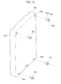
Figs. 11 and12 , each of thebatteries 104 is formed in a rectangular plate shape, andinsertion holes 104a are formed in the respective four corners of thebattery 104 in a manner that makes theinsertion holes 104a penetrate thebattery 104 in a plate-thickness direction. Thebattery 104 is a secondary battery such as a lithium ion secondary battery, a nickel hydrogen secondary battery, or a nickel cadmium secondary battery. Themultiple batteries 104 are arranged side by side in a row (in the thickness direction of the batteries 104).First connection members 107 serving as connection members,second connection members 108 serving as connection members, and spacers Ia9 are provided between thebatteries 104. - One of the
first connection members 107 and one of thesecond connection members 108 are disposed together between each adjacent two of thebatteries 104. In other words, the multiplefirst connection members 107 are arranged in the direction of the row of thebatteries 104 with intervals in between, and the multiplesecond connection members 108 are arranged in the direction of the row of thebatteries 104 with intervals in between. - As shown in
Fig. 11 , thefirst connection member 107 includes: aplate portion 107a to be interposed between each twoadjacent batteries 104; pairedcylinder portions 107b penetrating theplate portion 107a; pairedattachment portions 107c formed by being bent from theplate portion 107a; andbolt portions 107d fixed to therespective attachment portions 107c. Thefirst connection member 107 is disposed between each twoadjacent batteries 104 with end portions of thecylinder portions 107b fitted into theinsertion holes 104a of thebattery 104 on the front side, and with theplate portion 107a interposed between theadjacent batteries 104. Meanwhile, thesecond connection member 108 includes: aplate portion 108a to be interposed between each twoadjacent batteries 104; pairedcylinder portions 108b penetrating theplate portion 108a; anattachment portion 108c formed by being bent from theplate portion 108a; and abolt portion 108d fixed to theattachment portion 108c. Thesecond connection member 108 is disposed between each twoadjacent batteries 104 with end portions of thecylinder portions 108b fitted into theinsertion holes 104a of thebattery 104 on the rear side, and with theplate portion 108a interposed between theadjacent batteries 104. Thus, thefirst connection member 107 and thesecond connection member 108 thus disposed between each twoadjacent batteries 104 cause theadjacent batteries 104 to be positioned to each other, and form a gap between theadjacent batteries 104. - The
spacers 109 are disposed in a space between the each twoadjacent batteries 104 in which neither thefirst connection member 107 nor thesecond connection member 108 is disposed. Each of thespacers 109 includes a cylinder portion 109a. and aflange portion 109b provided on the circumferential surface of thecylinder portion 109a. Thespacers 109 are disposed between each twoadjacent batteries 104, matching theinsertion holes 104a of thebatteries 104. Eachspacer 109 is disposed between each twoadjacent batteries 104 with the end portion of thecylinder portion 109a fitted into thecorresponding insertion hole 104a of thebattery 104, and with theflange portion 109b interposed between theadjacent batteries 104. Thespacers 109 thus disposed cause theadjacent batteries 104 to be positioned to each other, and form a gap between theadjacent batteries 104. Moreover,different spacers 110 are disposed between eachendmost battery 104 and itscorresponding end plate 111. - As shown in
Figs. 6 to 10 , theframe 105 includes: pairedend plates 111 sandwiching the stackedmultiple batteries 104; multiple through-bolts 112 inserted in theend plates 111 and themultiple batteries 104 in the direction of the row of thebatteries 104;stack members 43 situated on the outer side of thebatteries 104, and extending in the direction of the row of thebatteries 104; and astack plate 114. - The through-
bolts 112 are provided, matching therespective insertion holes 104a of eachbattery 104. The two through-bolts 112 on the rear side are respectively inserted in thecylinder portions 107b of thefirst connection members 107 and thecylinder portions 109a of thespacers 109 as well. Meanwhile, the two through-bolts on the front side are inserted in thecylinder portions 108b of thesecond connection member 108 and thecylinder portions 109a of thespacers 109 as well. Then,nuts 115 are screwed to the through-bolts 102, respectively. Thus, the through-bolts 112 support themultiple batteries 104, and the pairedend plates 111 hold themultiple batteries 104 between theend plates 111. While in this state, the two throughbolts 112 on the rear side are connected to thefirst connection members 107, and the two throughbolts 112 on the front side are connected to thesecond connection members 108. - As shown in
Fig. 7 , each of thestack members 43 is formed in a band plate-like shape, and is provided on the rear side of thebattery module 103. An extendingportion 43 a is formed in each of the two end portions of thestack member 43. Moreover, multiple first insertion holes (not shown) are formed in thestack members 43, matching thefirst connection members 107, respectively. Thebolt portions 107d of thefirst connection members 107 are inserted in the first insertion holes, andnuts 116 are screwed to thebolt portions 107d, respectively. Thus, thefirst connection members 107 are fixed to thestack members 43. In other words, thefirst connection members 107 link together thestack member 43 and the through-bolts 112 on the front side. Note that a center line CL inFig. 7 indicates a center position of thebattery module 103 in the direction of the row (longitudinal direction). - As shown in
Figs. 8 and9 , thestack plate 114 is formed in a band plate-like shape, and is provided on the front side of thebattery module 103. Anattachment portion 114a is formed in each of the two end portions of thestack plate 114 by bending. Aninsertion hole 114b is formed in theattachment portion 114a, penetrating theattachment portion 114a in the direction of the row of thebatteries 104. Anut 114c is fixed to theattachment portion 114a. Thenut 114c communicates with theinsertion hole 114b. Moreover, multiple second insertion holes (not shown) are formed in thestack plate 114, matching thesecond connection members 108, respectively. Thebolt portions 108d of thesecond connection members 108 are inserted in the second insertion holes, andnuts 117 are screwed to thebolt portions 108d, respectively. Thus, thesecond connection members 108 are fixed to thestack plate 114. In other words, thesecond connection members 108 link thestack plate 114 and the through-bolts 112 on the front side to each other. - As shown in
Figs. 6 and9 , areinforcement plate 118 is fixed to each of theend plates 111. Afirst attachment portion 118a is formed in a stack member 43-side end portion of thereinforcement plate 118 by bending, and pairedsecond attachment portions 118b are formed in a stack plate 114-side end portion of thereinforcement plate 118 by bending. Anengagement hole 118c serving as a first engaging portion is formed in each of thesecond attachment portions 118b. - In the
battery module 103 including themultiple batteries 104 and theframe 105, an interval between the connection members (thefirst connection members 107 and the second connection members 108) adjacent to each other in the direction of the row of thebatteries 104 becomes smaller from the ends toward the center in the direction of the row of thebatteries 104 of thebattery module 103. - Each of the
battery modules 103 is supported at both end portions 103b in the direction of the row of thebatteries 104. Moreover, each of thestack members 43, thestack plate 114, and the through-bolts 112 are supported at both ends thereof. In this state, a space is provided between each twobattery modules 103 vertically adjacent to each other, and a space is provided below thelowermost battery module 103. Thebatteries 104 are designed to be cooled by the air flowing through these spaces. - A main frame, which is not illustrated, includes first and
second pillar members second pillar members battery module 103 in the direction of the row, and the like, as well as is configured to be fixed to a vehicle body. The first andsecond pillar members battery module 103. - As shown in
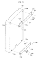
Figs. 13(a) and 13(b) , thefirst pillar member 121 includes: a pillarmain body 123 formed of a plate member; andmultiple pin members 124 fixed to the pillarmain body 123, and serving as second engagement portions. - As shown in
Fig. 13(c) , a taperedportion 124a having a circular truncated cone shape whose diameter becomes smaller toward the tip is formed in an end portion of each of thepin members 124. The taperedportion 124a is inserted in and is thus engaged with the corresponding one of the engagement holes 118c of thereinforcement members 118. Thepin member 124 is specifically a screw Note that the taperedportion 124a may be formed integrally with thepin member 124, as shown inFig. 13(c) . Alternatively, like a pin member 224 shown inFig. 13(d) , a separate taperedcap 224a may be fitted to an end of the pin member 224. - The pillar
main body 123 is formed of: a firstflat plate portion 123a; a secondflat plate portion 123b formed by being bent from a side edge of the firstflat plate portion 123a; a thirdflat plate portion 123c formed by being bent from a side edge of the secondflat plate portion 123b; and a fourthflat plate portion 123d formed by being bent from the thirdflat plate portion 123c. Accordingly, the pillarmain body 123 has an almost W-shaped cross section. - In the first
flat plate portion 123a, thepin members 124 are arranged with an interval between each twoadjacent pin members 124 in the longitudinal direction of thefirst pillar member 121. Moreover, apin member 126 different from thepin members 124 is also fixed to the firstflat plate portion 123a. - In the fourth
flat plate portion 123d,insertion holes 123e are formed with an interval between each twoadjacent insertion holes 123e in the longitudinal direction of thepillar member 121, andinsertion holes 123f are formed with an interval between the insertion holes 123f in the longitudinal direction of thepillar member 121. Each of theinsertion holes 123f is positioned between the corresponding twoadjacent insertion holes 123e, and one of theinsertion holes 123f is provided with anut 125. Thenut 125 is fixed to the fourthflat plate portion 123d by welding or the like, and communicates with the oneinsertion hole 123f. - The
second pillar member 122 is basically the same as thefirst pillar member 121, and is formed to be right-left symmetrical with respect to the first pillar member. - As shown in
Figs. 14(a) and 14(b) , thesecond pillar member 122 includes: a pillarmain body 128 formed of a plate member; andmultiple pin members 129 fixed to the pillarmain body 128, and serving as the second engagement portions. - A tapered
portion 129a whose diameter becomes smaller toward the tip is formed in an end portion of each of thepin members 129, as in the case of thepin members 124. The taperedportion 129a is engaged with the corresponding one of the engagement holes 118c of thereinforcement members 118 by being inserted in theengagement hole 118c. Thepin member 129 is a screw. Note that the taperedportion 129a may be formed integrally with thepin member 129. Alternatively, like the pin member described usingFig. 13 , a separate tapered cap (not shown) may be fitted to an end of a pin member. - The pillar
main body 128 is formed of: a firstflat plate portion 128a; a secondflat plate portion 128b formed by being bent from a side edge of the firstflat plate portion 128a; a thirdflat plate portion 128c formed by being bent from a side edge of the secondflat plate portion 128b; and a fourthflat plate portion 128d formed by being bent from the thirdflat plate portion 128c, as well as has an almost W-shaped cross section. - In the first
flat plate portion 128a, thepin members 129 are arranged with an interval between each twoadjacent pin members 129 in the longitudinal direction of thesecond pillar member 122. Moreover, apin member 130 different from thepin members 129 is also fixed to the firstflat plate portion 128a. - In the fourth
flat plate portion 128d,insertion holes 128e are formed with an interval between each twoadjacent insertion holes 128e in the longitudinal direction of thepillar member 122, andinsertion holes 128f are formed with an interval between the insertion holes 128f in the longitudinal direction of thepillar member 122. Each of the insertion holes 128f are positioned between the corresponding twoadjacent insertion holes 128e. Thesecond pillar member 122 is not provided with a nut which corresponds to thenut 125 of thefirst pillar member 121. - Next, descriptions are given of a method of positioning the battery modules and a method of manufacturing the battery pack. The method of positioning the battery modules is a method of positioning the
battery modules 103 and the first andsecond pillar members battery modules 103 each including themultiple batteries 104 in a row, the first andsecond pillar members battery modules 103 in the direction of the row. Thebattery modules 103 and the first andsecond pillar members jig apparatus 200 shown inFig. 15 . - The
jig apparatus 200 includes: apallet 201; andbolts pillar members pallet 201 will be simply referred to as the lateral direction and the longitudinal direction, respectively. - The
pallet 201 includes: abase portion 201g shaped like a rectangular plate; andleg portions 201p formed integrally with the respective lower portions of thebase portion 201g. - In the upper surface of the
base portion 201g, paired supportingportions block portion 201c is formed between the paired supportingportions base portion 201g, pairedgroove portions portion 201a and theblock portion 201c, and in a portion between the supportingportion 201b and theblock portion 201c. Thegroove portions - Multiple
lateral groove portions 201f extending in the lateral direction are formed in the supportingportion 201a. Multiple lateral groove portions 201i extending in the lateral direction are formed in the supportingportion 201b. Thelateral groove portions 201f are formed with an interval between each two adjacentlateral groove portions 201f in the longitudinal direction, and the lateral groove portions 201i are formed with an interval between each two adjacent lateral groove portions 201i in the longitudinal direction. Moreover,multiple insertion holes 201h are formed in the supporting portion 201a. andmultiple insertion holes portion 201b. The insertion holes 201h are formed with an interval in between in the longitudinal direction, and theinsertion holes portion 201a in the lateral direction, and theinsertion holes portion 201b in the lateral direction. The corresponding one of thebolts insertion holes reinforcement plates 201m are provided on the outer surface of each of the supportingportions insertion holes reinforcement plates 201m as well. Anupper surface 201r of theright supporting portion 201b functions as a slide support portion for slidably supporting thesecond pillar member 122 in a way that enables the adjustment of an interval between the first andsecond pillar members batteries 104, and the adjustment of relative positions of the respective first andsecond pillar members batteries 104. - Screw holes 201n are formed in both side portions of the
block portion 201c, situated coaxial with therespective insertion holes portion - In the method of manufacturing the battery pack, the
battery modules 103 are mounted on thepallet 201 with the first andsecond pillar members batteries 104 coincides with the lateral direction of thepallet 201; and the direction orthogonal to the direction of the row of thebatteries 104 coincides with the longitudinal direction of thepallet 201. - In the method of manufacturing the battery pack, firstly, as shown in
Fig. 16 , the first andsecond pillar members - To be more specific, the
first pillar member 121 is mounted on the one (left) supportingportion 201a, and thesecond pillar member 122 is mounted on the other (right) supportingportion 201b. At this time, the thirdflat plate portions second pillar members upper surfaces portions flat plate portions second pillar members inner surfaces 201s (an inner surface of the supportingportion 201b is not shown) of the supportingportions - Then, the
bolt 204 is inserted in theinsertion hole 201h of the one (left) supportingportion 201a on a far side and in theinsertion hole 123f of thefirst pillar member 121 on the far side. Subsequently, thebolt 204 is screwed to thenut 125, Subsequently, thebolt 205 is inserted in theinsertion hole 201h of the supportingportion 201a on a near side and in theinsertion hole 123f of thefirst pillar member 121 on the near side. Thereafter, thebolt 205 is screwed to thecorresponding screw hole 201n. Thus, thefirst pillar member 121 is fixed to thepallet 201. - After that, the
bolt 205 is inserted in theinsertion hole 201j of the other (right) supportingportion 201b on the far side and in theinsertion hole 128f of thesecond pillar member 122 on the far side. Subsequently, thebolt 205 is screwed to thecorresponding screw hole 201n. Concurrently, thebolt 205 is inserted in theinsertion hole 201k of the supportingportion 201b on the near side and in theinsertion hole 128f of thesecond pillar member 122 on the near side. Thereafter, thebolt 205 is screwed to thecorresponding screw hole 201n. While in this state, thesecond pillar member 122 is supported by theupper surface 201r of the supportingportion 201b, movable in the longitudinal direction and the lateral direction. To be more specific, thesecond pillar member 122 is movable in a direction toward thefirst pillar member 121, which is the lateral direction. Thus, thesecond pillar member 122 is slidably supported by theupper surface 201r of the supportingportion 201b in a way that enables the adjustment of the interval between the first andsecond pillar members second pillar members 123f 128f of the first andsecond pillar members bolts 205, and there is a backlash between each of theinsertion holes corresponding bolts 205. Accordingly, the insertion holes 128f allow thesecond pillar member 122 to move in the lateral direction (the direction of the row of the batteries 104) and in the longitudinal direction (the direction orthogonal to the direction of the row of the batteries 104), with thebolts 205 being inserted. Moreover, while in this state, the turn of thefirst pillar member 121, specifically the turn thereof about an imaginary axis extending in the longitudinal direction, is prevented by thebolts second pillar member 122, specifically the turn thereof about an imaginary axis extending in the longitudinal direction, is prevented by thebolts 205. - Next, as shown in
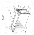
Fig. 17 ,slingers 206 are fixed to the two respective end portions of thebattery module 103 bybolts - Subsequently, as shown in
Fig. 18 , theslingers 206 are hooked to a crane (not shown), and thebattery module 103 is moved to a position above thejig apparatus 200 by the crane. Then, as shown inFigs. 19 and20 , thebattery module 103 is lowered (moved) toward the first andsecond pillar members jig apparatus 200. Thereafter, thepin members second pillar members battery module 103, and the first andsecond pillar members battery module 103 are positioned relative to one another (a relative positioning step). At this time, thetapered portions 129a of thepin members 129 are inserted into the insertion holes 118b while being in contact with theinsertion holes 118b, and this causes thesecond pillar member 122 to be automatically positioned to thebattery module 103. - After the positioning is completed in the foregoing manner,
nuts 209 are screwed to thepin members battery module 103 is thereby fixed to the first andsecond pillar members 121, 122 (a fixing step). The remaining twobattery modules 103 are positioned and fixed to the first andsecond pillar members Fig. 20 ). - Next, a
bolt 210 is screwed to each of the nuts 114c of the extendingportions 43a of the second supportingmember 113 of thebattery modules 103, and thus the extendingportions 43a are fixed to the first andsecond pillar members 121, 122 (seeFig. 21 ). At this time, thebolts 210 can by screwed to the nuts 114c by inserting thebolts 210 into thelateral groove portions 201f. 201i. Then, theslingers 206 are removed from thebattery modules 103. Frame members other than the first andsecond pillar members battery modules 103. Thus, the assembly of thebattery pack 102 is completed. Thebattery pack 102 can be detached from thepallet 201 by removing thebolts - Next, operations and effects of the second embodiment will be described below.
-
- (1) The embodiment enables the adjustment of the interval between the first and
second pillar members batteries 104, and the adjustment of the relative positions of the respective first andsecond pillar members battery module 103 in the direction of the row of thebatteries 104. -
- (2) Moreover, in the present embodiment, the turn prevention members are the
bolts second pillar member 122 being one of the pillar members has the insertion holes 128f which allow the movement of thepillar member 122 in the direction of the row of thebatteries 104, and in the direction orthogonal to the direction of the row, with thebolts 205 being inserted. Accordingly, the relatively simple configuration makes it possible to prevent the turn of thesecond pillar member 122 while allowing the movement of thesecond pillar member 122. -
- (3) Furthermore, in the embodiment, engaged portions are the
engagement holes 118c; and engaging portions are thepin members portions tapered portions pin members - It should be noted that the entireties of Japanese Patent Application No.
2009-106895 2009-106856 - Moreover, the present invention is not limited to the embodiments describe above, and can employ other various embodiments within the scope not departing from the gist of the present invention.
- For example, in the second embodiment, the slide support portion is not limited to the
upper surface 201r of the other supportingportion 201b, and may be theupper surface 201 q of the one supportingportion 201a. In this case, thescrew hole 201n is provided instead of thenut 125. In this case, theupper surface 201q slidably supports thefirst pillar member 121 in a way that enables the adjustment of the interval between the first andsecond pillar members second pillar members upper surfaces portions - Note that the present invention includes the following characteristics.
-
- (1) The method of positioning the
battery modules 103, in which thebattery modules 103 each including themultiple batteries 104 arranged in a row and the pairedpillar members battery modules 103 in the direction of the row are positioned relative to one another, the method including the steps of: assembling the pairedpillar members jig apparatus 200 enabling the adjustment of the interval between the pairedpillar members pillar members pillar members battery modules 103 relative to one another by: moving the pairedpillar members jig apparatus 200, and thebattery modules 103 relative to one another; engaging the engaged portions of thebattery modules 103 and the engaging portions of the pairedpillar members pillar members respective pillar members -
- (2) The method of positioning the battery modules, wherein: the
jig apparatus 200 is provided with thebolts pillar members bolts bolts -
- (3) The method of positioning the battery modules, wherein: the engaged portions are the engagement holes; and the engaging portions are the
pin members 129 each having the tapered portion which is formed in a way that makes the tapered portion become smaller in diameter toward a tip portion. -
- (4) The
jig apparatus 200 for thebattery pack 102 which includes: thepallet 201 including the slide support portion; and thebolts jig apparatus 200 capable of positioning thebattery modules 103 and the pairedpillar members battery pack 102 in which both end portions of thebattery modules 103 in the direction of the row are supported by the pairedpillar members jig apparatus 200 wherein at least one of the pairedpillar members pillar members pillar members pillar members - The present invention makes it possible to reduce the overall volume of the battery pack, because the accessories are attached to the side surfaces of the supporting members disposed on the sides where the extending portions of the stack members.
- In other words, if the accessories would be disposed on a side surface on a side different from the sides where the extending portions of the stack members are disposed, the volume would be increased by the extending portions on the side where the extending portions are disposed, while the volume would be increased by the accessories on the side where the accessories are provided. For this reason, disposing the accessories on the side surfaces on the sides where the extending portions are disposed makes it possible to reduce the overall volume of the battery pack.
-
- 1
- BATTERY PACK
- 3
- UPPER BATTERY MODULE (BATTERY MODULE)
- 5
- CENTER BATTERY MODULE (BATTERY MODULE)
- 7
- LOWER BATTERY MODULE (BATTERY MODULE)
- 9
- BATTERY
- 12
- ACCESSORIES
- 13
- BATTERY CONTROLLER (ACCESSORY)
- 14
- WIRE HARNESS (ACCESSORY)
- 16
- ATTACHMENT PLATE (ACCESSORY)
- 35
- SUPPORTING MEMBER
- 36
- END PLATE (SUPPORTING MEMBER)
- 37
- REINFORCEMENT MEMBER (SUPPORTING MEMBER)
- 43
- STACK MEMBER
- 43a
- EXTENDING PORTION
- 51
- SUPPORTING BRACKET
Claims (2)
- A battery pack comprising:paired supporting members disposed with a predetermined interval in between;a battery module disposed between the supporting members; anda stack member supporting the battery module by linking the supporting members to each other, whereinan extending portion protruding from the battery module is formed by extending an end portion of the stack member in an extending direction of the stack member, and the supporting member and the extending portion of the stack member are connected to each other by a supporting bracket, andaccessories are attached to at least a side surface on a side where the extending portion of the stack member is disposed, among side surfaces of the battery pack which are provided with the paired supporting members.
- The battery pack according to claim 1, wherein a length by which the extending portion of the stack member protrudes from the battery module is set larger than a length by which the accessories protrude from the battery module.
Applications Claiming Priority (3)
| Application Number | Priority Date | Filing Date | Title |
|---|---|---|---|
| JP2009106895 | 2009-04-24 | ||
| JP2009106856 | 2009-04-24 | ||
| PCT/JP2010/057216 WO2010123091A1 (en) | 2009-04-24 | 2010-04-23 | Battery pack |
Publications (2)
| Publication Number | Publication Date |
|---|---|
| EP2423999A1 true EP2423999A1 (en) | 2012-02-29 |
| EP2423999A4 EP2423999A4 (en) | 2014-03-26 |
Family
ID=43011205
Family Applications (1)
| Application Number | Title | Priority Date | Filing Date |
|---|---|---|---|
| EP10767146.3A Withdrawn EP2423999A4 (en) | 2009-04-24 | 2010-04-23 | BATTERY PACK |
Country Status (10)
| Country | Link |
|---|---|
| US (2) | US8592068B2 (en) |
| EP (1) | EP2423999A4 (en) |
| JP (1) | JP5413457B2 (en) |
| KR (1) | KR101248688B1 (en) |
| CN (1) | CN102414866B (en) |
| BR (1) | BRPI1014493A2 (en) |
| IL (1) | IL215779A0 (en) |
| MX (1) | MX2011011002A (en) |
| RU (1) | RU2495517C2 (en) |
| WO (1) | WO2010123091A1 (en) |
Cited By (3)
| Publication number | Priority date | Publication date | Assignee | Title |
|---|---|---|---|---|
| EP2899773A4 (en) * | 2012-09-18 | 2015-12-16 | Nissan Motor | ASSEMBLED BATTERY |
| WO2021199070A1 (en) * | 2020-04-01 | 2021-10-07 | Tvs Motor Company Limited | A battery block |
| EP4372877A1 (en) * | 2022-11-15 | 2024-05-22 | CALB Group Co., Ltd. | Battery module and battery pack |
Families Citing this family (26)
| Publication number | Priority date | Publication date | Assignee | Title |
|---|---|---|---|---|
| JP5442268B2 (en) * | 2009-01-28 | 2014-03-12 | 三洋電機株式会社 | Battery system |
| KR101191662B1 (en) * | 2010-11-05 | 2012-10-17 | 에스비리모티브 주식회사 | Battery module |
| CN103201876B (en) * | 2010-11-17 | 2015-11-25 | 本田技研工业株式会社 | Vehicle battery unit |
| KR101303416B1 (en) | 2011-02-15 | 2013-09-05 | 로베르트 보쉬 게엠베하 | Battery module with improved housing |
| US8968912B2 (en) * | 2011-12-21 | 2015-03-03 | Ford Global Technologies, Llc | Method and apparatus for manufacturing a battery for a vehicle |
| AT513127B1 (en) * | 2012-08-21 | 2014-02-15 | Avl List Gmbh | Electric energy storage |
| JP6132284B2 (en) * | 2013-05-30 | 2017-05-24 | Fdk株式会社 | Spacer |
| US9590217B2 (en) | 2013-08-07 | 2017-03-07 | Nissan Motor Co., Ltd. | Structure for mounting battery on vehicle |
| US9543556B2 (en) | 2013-10-18 | 2017-01-10 | Ford Global Technologies, Llc | Battery assembly |
| JP6206308B2 (en) * | 2014-04-11 | 2017-10-04 | 株式会社豊田自動織機 | Battery pack |
| JP6318862B2 (en) * | 2014-05-29 | 2018-05-09 | 株式会社豊田自動織機 | Battery module and battery pack |
| US9911951B2 (en) | 2014-09-30 | 2018-03-06 | Johnson Controls Technology Company | Battery module compressed cell assembly |
| KR101805650B1 (en) * | 2015-08-28 | 2017-12-06 | 삼성에스디아이 주식회사 | Rechargeable battery pack |
| KR101805652B1 (en) | 2015-08-28 | 2017-12-06 | 삼성에스디아이 주식회사 | Rechargeable battery pack |
| KR102091767B1 (en) * | 2015-10-22 | 2020-03-20 | 주식회사 엘지화학 | Battery Protecting Structure And Battery Module Comprising The Same |
| US10581126B2 (en) | 2016-05-09 | 2020-03-03 | Nikola Corporation | Electric battery assembly |
| US10308132B2 (en) | 2016-05-09 | 2019-06-04 | Nikola Corporation | Electric utility terrain vehicle |
| US10497998B2 (en) | 2016-05-09 | 2019-12-03 | Nikola Corporation | Electric battery assembly |
| JP6310990B1 (en) * | 2016-10-26 | 2018-04-11 | 本田技研工業株式会社 | Battery module fixing structure |
| KR102249896B1 (en) * | 2016-11-08 | 2021-05-07 | 삼성에스디아이 주식회사 | Rechargeable battery module and pack |
| DE102019211359A1 (en) * | 2018-11-30 | 2020-06-04 | Robert Bosch Gmbh | Battery cell holder and battery system |
| CN111384325B (en) * | 2018-12-29 | 2021-02-12 | 宁德时代新能源科技股份有限公司 | Battery pack |
| CN209401684U (en) * | 2018-12-29 | 2019-09-17 | 宁德时代新能源科技股份有限公司 | battery pack |
| US11258128B2 (en) * | 2020-01-22 | 2022-02-22 | Ford Global Technologies, Llc | Battery pack reinforcement assemblies |
| JP7714884B2 (en) * | 2021-02-12 | 2025-07-30 | 株式会社Gsユアサ | Power storage device |
| JP7380728B2 (en) * | 2022-03-15 | 2023-11-15 | いすゞ自動車株式会社 | Fixing structure and fixing method of vehicle battery box |
Family Cites Families (17)
| Publication number | Priority date | Publication date | Assignee | Title |
|---|---|---|---|---|
| FR1600393A (en) * | 1968-12-31 | 1970-07-20 | ||
| FR2344133A1 (en) * | 1976-03-09 | 1977-10-07 | Accumulateurs Fixes | ACCUMULATOR BATTERY CHASSIS |
| GB1537108A (en) * | 1976-08-20 | 1978-12-29 | Chloride Group Ltd | Cell racks for holding electric cells |
| SU1762343A1 (en) * | 1990-04-02 | 1992-09-15 | С.А.Ивашков | Storage battery |
| JP3365577B2 (en) * | 1994-05-27 | 2003-01-14 | 松下電器産業株式会社 | Single-cell and unit cells of sealed nickel-hydrogen storage batteries |
| JPH08264170A (en) * | 1995-03-27 | 1996-10-11 | Yuasa Corp | Assembly battery device |
| JP3271494B2 (en) * | 1995-10-24 | 2002-04-02 | 松下電器産業株式会社 | Stacked sealed alkaline storage battery |
| JP4088360B2 (en) * | 1997-10-20 | 2008-05-21 | 松下電器産業株式会社 | Collective sealed secondary battery |
| JP3702149B2 (en) * | 2000-05-31 | 2005-10-05 | 三洋電機株式会社 | Power supply |
| JP2004311290A (en) * | 2003-04-09 | 2004-11-04 | Toyota Motor Corp | Battery pack temperature difference reduction device and battery pack |
| JP4629405B2 (en) * | 2004-10-22 | 2011-02-09 | 矢崎総業株式会社 | Battery resin cover assembly structure and assembly method |
| KR100857021B1 (en) | 2004-12-10 | 2008-09-05 | 주식회사 엘지화학 | Rechargeable Battery Pack |
| JP4783137B2 (en) | 2005-12-15 | 2011-09-28 | 日立ビークルエナジー株式会社 | Battery module |
| JP5100140B2 (en) * | 2007-01-30 | 2012-12-19 | 三洋電機株式会社 | Battery pack and manufacturing method thereof |
| JP5023969B2 (en) | 2007-10-30 | 2012-09-12 | マツダ株式会社 | Exhaust gas component purification catalyst material and particulate filter with the catalyst material |
| JP5040594B2 (en) | 2007-10-31 | 2012-10-03 | 住友大阪セメント株式会社 | Method for reducing moisture content of dehydrated organic waste, method for converting low moisture content organic waste into fuel, biomass fuel, and facility for reducing moisture content of dehydrated organic waste |
| RU76169U1 (en) * | 2008-04-04 | 2008-09-10 | Общество с ограниченной ответственностью "Национальная инновационная компания "Новые энергетические проекты" (ООО "Национальная инновационная компания "НЭП") | EXPERIMENTAL BATTERY HOUSING |
-
2010
- 2010-04-23 US US13/265,453 patent/US8592068B2/en not_active Expired - Fee Related
- 2010-04-23 WO PCT/JP2010/057216 patent/WO2010123091A1/en not_active Ceased
- 2010-04-23 KR KR1020117024916A patent/KR101248688B1/en not_active Expired - Fee Related
- 2010-04-23 CN CN201080018195.2A patent/CN102414866B/en not_active Expired - Fee Related
- 2010-04-23 RU RU2011147728/07A patent/RU2495517C2/en not_active IP Right Cessation
- 2010-04-23 MX MX2011011002A patent/MX2011011002A/en active IP Right Grant
- 2010-04-23 JP JP2011510372A patent/JP5413457B2/en not_active Expired - Fee Related
- 2010-04-23 BR BRPI1014493A patent/BRPI1014493A2/en not_active IP Right Cessation
- 2010-04-23 EP EP10767146.3A patent/EP2423999A4/en not_active Withdrawn
-
2011
- 2011-10-23 IL IL215779A patent/IL215779A0/en unknown
-
2013
- 2013-11-12 US US14/077,975 patent/US9130210B2/en not_active Expired - Fee Related
Cited By (4)
| Publication number | Priority date | Publication date | Assignee | Title |
|---|---|---|---|---|
| EP2899773A4 (en) * | 2012-09-18 | 2015-12-16 | Nissan Motor | ASSEMBLED BATTERY |
| US9742025B2 (en) | 2012-09-18 | 2017-08-22 | Nissan Motor Co., Ltd. | Battery pack |
| WO2021199070A1 (en) * | 2020-04-01 | 2021-10-07 | Tvs Motor Company Limited | A battery block |
| EP4372877A1 (en) * | 2022-11-15 | 2024-05-22 | CALB Group Co., Ltd. | Battery module and battery pack |
Also Published As
| Publication number | Publication date |
|---|---|
| RU2495517C2 (en) | 2013-10-10 |
| IL215779A0 (en) | 2012-01-31 |
| CN102414866A (en) | 2012-04-11 |
| US20120040237A1 (en) | 2012-02-16 |
| MX2011011002A (en) | 2011-11-02 |
| KR101248688B1 (en) | 2013-04-01 |
| BRPI1014493A2 (en) | 2016-04-05 |
| EP2423999A4 (en) | 2014-03-26 |
| RU2011147728A (en) | 2013-07-27 |
| US8592068B2 (en) | 2013-11-26 |
| US9130210B2 (en) | 2015-09-08 |
| JPWO2010123091A1 (en) | 2012-10-25 |
| US20140065458A1 (en) | 2014-03-06 |
| JP5413457B2 (en) | 2014-02-12 |
| CN102414866B (en) | 2015-11-25 |
| KR20120007009A (en) | 2012-01-19 |
| WO2010123091A1 (en) | 2010-10-28 |
Similar Documents
| Publication | Publication Date | Title |
|---|---|---|
| US9130210B2 (en) | Battery pack | |
| US9859532B2 (en) | Battery module and method incorporating exterior casing and liner | |
| EP2544262B1 (en) | Battery connection assembly | |
| EP3412486A1 (en) | Battery mounting structure | |
| US8557428B2 (en) | Battery module and battery pack including the same | |
| EP1852925A1 (en) | Battery pack | |
| EP2593982B1 (en) | Battery cell module, battery, and motor vehicle | |
| JP5862077B2 (en) | Battery wiring module | |
| JP5813430B2 (en) | Connecting member for power supply body, bus bar module, and power supply device including the bus bar module | |
| US9893340B2 (en) | Battery wiring module | |
| CN115279609A (en) | Vehicle battery system | |
| US20140342212A1 (en) | Cell contacting arrangement for an energy storage module | |
| KR20180058801A (en) | A battery case having a rail engaged with a protruding slot fixing means | |
| US11990635B2 (en) | Frame structure assembly kit, battery module, and method for manufacturing battery module | |
| EP3223339A1 (en) | Battery compression inhibitor and battery module comprising same | |
| US20240075799A1 (en) | Traction battery pack support system and method of securing a battery pack to an electrified vehicle | |
| CN108713263B (en) | Battery pack including tray stop to prevent battery pack cover from springing back | |
| EP2899773B1 (en) | Assembled battery | |
| JP2011175928A (en) | Battery connection assembly | |
| JP2012059451A (en) | Bus bar module, power storage device | |
| WO2024220348A1 (en) | High voltage battery enclosure for vehicle | |
| JP2013020798A (en) | Cover of battery wiring module, battery wiring module, and battery module | |
| KR102739751B1 (en) | Catridge for battery cell having counterbar hole and battery module assembly including the same | |
| US20260066427A1 (en) | Battery pack | |
| US20240204367A1 (en) | Bus bar retention systems for traction battery packs |
Legal Events
| Date | Code | Title | Description |
|---|---|---|---|
| PUAI | Public reference made under article 153(3) epc to a published international application that has entered the european phase |
Free format text: ORIGINAL CODE: 0009012 |
|
| 17P | Request for examination filed |
Effective date: 20111123 |
|
| AK | Designated contracting states |
Kind code of ref document: A1 Designated state(s): AT BE BG CH CY CZ DE DK EE ES FI FR GB GR HR HU IE IS IT LI LT LU LV MC MK MT NL NO PL PT RO SE SI SK SM TR |
|
| DAX | Request for extension of the european patent (deleted) | ||
| A4 | Supplementary search report drawn up and despatched |
Effective date: 20140226 |
|
| RIC1 | Information provided on ipc code assigned before grant |
Ipc: H01M 2/10 20060101AFI20140220BHEP |
|
| 17Q | First examination report despatched |
Effective date: 20160913 |
|
| STAA | Information on the status of an ep patent application or granted ep patent |
Free format text: STATUS: THE APPLICATION IS DEEMED TO BE WITHDRAWN |
|
| 18D | Application deemed to be withdrawn |
Effective date: 20170124 |