EP2423997A1 - Battery pack comprising a cover with a resilient material - Google Patents
Battery pack comprising a cover with a resilient material Download PDFInfo
- Publication number
- EP2423997A1 EP2423997A1 EP11170500A EP11170500A EP2423997A1 EP 2423997 A1 EP2423997 A1 EP 2423997A1 EP 11170500 A EP11170500 A EP 11170500A EP 11170500 A EP11170500 A EP 11170500A EP 2423997 A1 EP2423997 A1 EP 2423997A1
- Authority
- EP
- European Patent Office
- Prior art keywords
- battery pack
- bare cell
- upper cover
- cap plate
- lead member
- Prior art date
- Legal status (The legal status is an assumption and is not a legal conclusion. Google has not performed a legal analysis and makes no representation as to the accuracy of the status listed.)
- Granted
Links
Images


Classifications
-
- H—ELECTRICITY
- H01—ELECTRIC ELEMENTS
- H01M—PROCESSES OR MEANS, e.g. BATTERIES, FOR THE DIRECT CONVERSION OF CHEMICAL ENERGY INTO ELECTRICAL ENERGY
- H01M10/00—Secondary cells; Manufacture thereof
- H01M10/04—Construction or manufacture in general
- H01M10/0431—Cells with wound or folded electrodes
-
- H—ELECTRICITY
- H01—ELECTRIC ELEMENTS
- H01M—PROCESSES OR MEANS, e.g. BATTERIES, FOR THE DIRECT CONVERSION OF CHEMICAL ENERGY INTO ELECTRICAL ENERGY
- H01M10/00—Secondary cells; Manufacture thereof
- H01M10/42—Methods or arrangements for servicing or maintenance of secondary cells or secondary half-cells
- H01M10/425—Structural combination with electronic components, e.g. electronic circuits integrated to the outside of the casing
-
- H—ELECTRICITY
- H01—ELECTRIC ELEMENTS
- H01M—PROCESSES OR MEANS, e.g. BATTERIES, FOR THE DIRECT CONVERSION OF CHEMICAL ENERGY INTO ELECTRICAL ENERGY
- H01M50/00—Constructional details or processes of manufacture of the non-active parts of electrochemical cells other than fuel cells, e.g. hybrid cells
- H01M50/10—Primary casings; Jackets or wrappings
- H01M50/147—Lids or covers
- H01M50/148—Lids or covers characterised by their shape
- H01M50/15—Lids or covers characterised by their shape for prismatic or rectangular cells
-
- H—ELECTRICITY
- H01—ELECTRIC ELEMENTS
- H01M—PROCESSES OR MEANS, e.g. BATTERIES, FOR THE DIRECT CONVERSION OF CHEMICAL ENERGY INTO ELECTRICAL ENERGY
- H01M50/00—Constructional details or processes of manufacture of the non-active parts of electrochemical cells other than fuel cells, e.g. hybrid cells
- H01M50/20—Mountings; Secondary casings or frames; Racks, modules or packs; Suspension devices; Shock absorbers; Transport or carrying devices; Holders
- H01M50/202—Casings or frames around the primary casing of a single cell or a single battery
-
- H—ELECTRICITY
- H01—ELECTRIC ELEMENTS
- H01M—PROCESSES OR MEANS, e.g. BATTERIES, FOR THE DIRECT CONVERSION OF CHEMICAL ENERGY INTO ELECTRICAL ENERGY
- H01M50/00—Constructional details or processes of manufacture of the non-active parts of electrochemical cells other than fuel cells, e.g. hybrid cells
- H01M50/20—Mountings; Secondary casings or frames; Racks, modules or packs; Suspension devices; Shock absorbers; Transport or carrying devices; Holders
- H01M50/233—Mountings; Secondary casings or frames; Racks, modules or packs; Suspension devices; Shock absorbers; Transport or carrying devices; Holders characterised by physical properties of casings or racks, e.g. dimensions
- H01M50/242—Mountings; Secondary casings or frames; Racks, modules or packs; Suspension devices; Shock absorbers; Transport or carrying devices; Holders characterised by physical properties of casings or racks, e.g. dimensions adapted for protecting batteries against vibrations, collision impact or swelling
-
- H—ELECTRICITY
- H01—ELECTRIC ELEMENTS
- H01M—PROCESSES OR MEANS, e.g. BATTERIES, FOR THE DIRECT CONVERSION OF CHEMICAL ENERGY INTO ELECTRICAL ENERGY
- H01M50/00—Constructional details or processes of manufacture of the non-active parts of electrochemical cells other than fuel cells, e.g. hybrid cells
- H01M50/20—Mountings; Secondary casings or frames; Racks, modules or packs; Suspension devices; Shock absorbers; Transport or carrying devices; Holders
- H01M50/271—Lids or covers for the racks or secondary casings
-
- Y—GENERAL TAGGING OF NEW TECHNOLOGICAL DEVELOPMENTS; GENERAL TAGGING OF CROSS-SECTIONAL TECHNOLOGIES SPANNING OVER SEVERAL SECTIONS OF THE IPC; TECHNICAL SUBJECTS COVERED BY FORMER USPC CROSS-REFERENCE ART COLLECTIONS [XRACs] AND DIGESTS
- Y02—TECHNOLOGIES OR APPLICATIONS FOR MITIGATION OR ADAPTATION AGAINST CLIMATE CHANGE
- Y02E—REDUCTION OF GREENHOUSE GAS [GHG] EMISSIONS, RELATED TO ENERGY GENERATION, TRANSMISSION OR DISTRIBUTION
- Y02E60/00—Enabling technologies; Technologies with a potential or indirect contribution to GHG emissions mitigation
- Y02E60/10—Energy storage using batteries
-
- Y—GENERAL TAGGING OF NEW TECHNOLOGICAL DEVELOPMENTS; GENERAL TAGGING OF CROSS-SECTIONAL TECHNOLOGIES SPANNING OVER SEVERAL SECTIONS OF THE IPC; TECHNICAL SUBJECTS COVERED BY FORMER USPC CROSS-REFERENCE ART COLLECTIONS [XRACs] AND DIGESTS
- Y02—TECHNOLOGIES OR APPLICATIONS FOR MITIGATION OR ADAPTATION AGAINST CLIMATE CHANGE
- Y02P—CLIMATE CHANGE MITIGATION TECHNOLOGIES IN THE PRODUCTION OR PROCESSING OF GOODS
- Y02P70/00—Climate change mitigation technologies in the production process for final industrial or consumer products
- Y02P70/50—Manufacturing or production processes characterised by the final manufactured product
Definitions
- a secondary battery includes an inflammable material, and in consideration of the stability of the secondary battery, the secondary battery has a circuit for efficiently controlling abnormal operation states including overcharge, overdischarge, overcurrent, and the like. Also, the secondary battery is used in the form of a battery pack having a cover so as to protect the circuit from an external environment.
- the characteristic that deteriorates most from among the reliability conditions is a falling characteristic, ie. the characteristic that defines the result of the battery falling or being dropped. This is because a shock resulting from a fall is increased according to an increase in the weight or volume of the battery pack. This causal relationship severely damages the battery pack in a free fall test, the biggest problem being that resistance of a charge-discharge path, which directly affects efficiency of the battery pack, is increased.
- One or more embodiments of the present invention include a battery pack which has increased reliability with respect to an external shock.
- One or more embodiments of the present invention include a battery pack in which electric resistance of a charge-discharge path remains at a low level, in spite of an external shock.
- a battery pack comprising a bare cell including a cap plate, a protection circuit module mounted to the cap plate and cover means mounted to the cap plate for covering the protection circuit module, wherein the cover means comprises side wall portions and end portions at respective ends of the sidewall portions, wherein the side wall portions comprise a first material and one or both of the end portions comprise a resilient end portion, the resilient end portion comprising a second material that is more resilient than the first material.
- shock transmitted when the cover hits a surface can be more efficiently absorbed.
- the side wall portions and the end portions may together provide a substantially continuous surface to be mounted to the cap plate.
- the cover means may comprise a cover having a top portion and the side wall portions may comprise first and second side wall portions extending from the top portion.
- the cover means may comprise a cover and at least one resilient end portion separate from the cover.
- the cover may comprise a cut-out portion for accommodating the or each resilient end portion.
- the cover means may comprise a cover in which the or each resilient end portion is integrally formed with the side wall portions.
- the top portion and the side wall portions may be formed of the same first material.
- the or each resilient end portion may further comprise a hole for receiving a coupling member that couples the cover means to the bare cell.
- the or each resilient end portion may comprise a first portion surrounding the hole and planar portions extending from the first portion to meet the side wall portions.
- the battery pack may further comprise a lead member for connecting the cap plate to the protection circuit module, wherein at least one of the resilient end portions is disposed on the lead member.
- the lead member By disposing the resilient end portion on the lead member, the lead member is protected from external shock.
- the or each resilient end portion may be compressed by the cover means so as to bias the lead member against the cap plate.
- the lead member is both protected by the resilient portion and the resilient portion assists in pressing the lead member against the cap plate so as to maintain a good electrical contact, even when the battery pack is dropped.
- the or each resilient end portion may be disposed between a mounting portion of the cover means that supports the coupling member and the lead member.
- the lead member and the or each resilient end portion may extend to the edge of the cap plate.
- the first and second resilient end portions may have the same thickness, wherein the first resilient end portion is disposed on the lead member and the second resilient end portion is disposed on the cap plate.
- the resilience of the end portions allows the same portion to be used irrespective of whether it rests on the lead member or just on the cap plate, so saving manufacturing cost.
- the cover means may comprise a single resilient end portion disposed on the lead member.
- a single resilient end portion may be used where its protection is most effective.
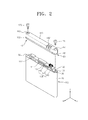
- FIGS. 1 to 3 are exploded perspective views of a battery pack according to an embodiment of the present invention.
- the battery pack includes a bare cell 100 capable of being charged and discharged, a protective circuit module (PCM) 150 mounted on the bare cell 100 so as to control charging and discharging operations of the bare cell 100, and an upper cover 160 coupled with the bare cell 100 so as to receive the PCM 150.
- PCM protective circuit module
- the bare cell 100 is a rechargeable, secondary battery, which may be formed of a lithium-ion battery, and has a structure in which an electrode assembly 10 including a positive electrode plate 11, a negative electrode plate 13, and a separator 15 is impregnated with an electrolyte (not shown) and then sealed in a can 20.
- the bare cell 100 includes the electrode assembly 10 in the shape of a jelly roll formed by rolling the positive electrode plate 11, the negative electrode plate 13, and the separator 15; the can 20 having an opening at its top surface so as to receive the electrode assembly 10 and the electrolyte; and a cap plate 30 for sealing the opening of the can 20.
- a contact between the cap plate 30 and the can 20 may be laser-welded to form a sealed combination.
- At least one of the positive electrode plate 11 and the negative electrode plate 13 may be connected to a positive electrode tab 17 and a negative electrode tab 19.
- the positive electrode tab 17 may be connected to the cap plate 30, and the negative electrode tab 19 may be connected to an electrode terminal 35 that projects upwardly from the cap plate 30.
- the electrode terminal 35 is coupled with but insulated from the cap plate 30, and projects upwardly from the cap plate 30.
- the PCM 150 functions to control the charging and discharging operations of the bare cell 100, and when overcurrent greater than a threshold value flows, when a temperature of the bare cell 100 exceeds a predetermined value, or when overcharge or overdischarge occurs, the PCM 150 blocks electric connection and performs a protective operation for protecting the bare cell 100.
- the PCM 150 may include a circuit substrate 140 having a sensing circuit (not shown) for detecting state information regarding a current, a voltage, and the like, and a charge-discharge protective circuit (not shown), and a protecting device 120 connected to the circuit substrate 140 and restricting a charge-discharge current according to a rise in temperature.
- the circuit substrate 140 may be formed of a printed circuit board (PCB) that includes a wire pattern (not shown) so as to form a charge-discharge current path between an external device (not shown) and the bare cell 100, and includes a protective circuit (not shown).
- An external connection terminal 145 for relaying electrical connection with the external device (not shown) may be arranged on the circuit substrate 140.
- the protecting device 120 forms a current path between the electrode terminal 35 of the cap plate 30 and the circuit substrate 140.
- the protecting device 120 may include a positive temperature coefficient (PTC) device or a temperature fuse.
- PTC positive temperature coefficient
- the PTC protecting device 120 may include a variable resistor 120c of which electric resistance value varies according to a temperature, and first and second connecting members 120a and 120b that are connected to the variable resistor 120c and extend in opposite directions.
- the first connecting member 120a is connected to the electrode terminal 35 of the cap plate 30, while the second connecting member 120b is connected to the circuit substrate 140.
- the positive electrode tab 17 and the negative electrode tab 19 of the bare cell 100 are electrically connected to electrode pads (not shown) of the circuit substrate 140, respectively.
- the negative electrode tab 19 of the bare cell 100 may be connected to a first electrode pad (not shown) of the circuit substrate 140 via the electrode terminal 35 and the protecting device 120
- the positive electrode tab 17 of the bare cell 100 may be connected to a second electrode pad (not shown) of the circuit substrate 140 via the cap plate 30 and a lead member 132.
- the lead member 132 may have a stepped form that is bent to have upper and lower portions that are stepped with respect to each other, and the upper portion may be connected to the circuit substrate 140 and the lower portion may extend to contact a top surface of the cap plate 30.
- the lead member 132 may be soldered to the second electrode pad (not shown) of the circuit substrate 140. Also, the lead member 132 may be fixed on the cap plate 30 by using a coupling member 171, and for this coupling, a through hole 131 for insertion of the coupling member 171 may be formed in the lead member 132.
- Insulating members 111 and 112 may be interposed between the PCM 150 and the bare cell 100.
- the insulating members 111 and 112 may include a first insulating member 111 formed to surround the electrode terminal 35, and a second insulating member 112 interposed between the cap plate 30 and the circuit substrate 140.
- the insulating members 111 and 112 function to fix the PCM 150 on the bare cell 100, and to prevent an electrical short between the bare cell 100 and the PCM 150.
- the insulating members 111 and 112 may provide elastic support between the PCM 150 and the bare cell 100, and to absorb a shock.
- another insulating member 113 may be disposed between the protecting device 120 and the cap plate 30.
- the upper cover 160 is coupled the bare cell 100 so as to receive the PCM 150.
- a terminal hole 160' of an opening pattern may be formed in the upper cover 160 so as to expose the external connection terminal 145, and to allow access with the external device (not shown).
- An insulating label sheet 199 having an adhesive coated thereon may be adhered to an outer surface of the bare cell 100.
- An adhering member 193 such as a double-sided adhesive tape is arranged on a bottom of the bare cell 100 so that a lower cover 195 may be coupled thereto.
- a reference numeral 190 of FIG. 1 indicates plug members that cover through holes 161 and 162 to which the coupling members 171 and 172 are inserted.
- shock absorbing layers 181 and 182 for absorbing or relieving an external shock are arranged at ends E1 and E2 of the upper cover 160.
- the shock absorbing layers 181 and 182 also referred to herein as resilient portions, or resilient end portions, may be arranged at the ends E1 and E2 along a long side (an X-direction) of the upper cover 160, and may include a first shock absorbing layer 181 arranged at a first end E1, and a second shock absorbing layer 182 arranged at a second end E2.
- the shock absorbing layers 181 and 182 may be coupled to a lower portion of the upper cover 160 facing the bare cell 100.
- the shock absorbing layers 181 and 182 may have forms that are symmetrical to each other, or may have different forms so as to be fit for structures of the ends E1 and E2 of the upper cover 160 to which the shock absorbing layers 181 and 182 are coupled.
- the shock absorbing layers 181 and 182 may be formed of a flexible, or resilient, material different from the upper cover 160, and any flexible material will do as long as the flexible material is more flexible than the upper cover 160 and is capable of absorbing an external shock.
- the upper cover 160 may be formed of a polycarbonate material
- the shock absorbing layers 181 and 182 may be formed of a silicon-based or rubber-based material that is more resilient than the upper cover 160.
- the material for forming the shock absorbing layers 181 and 182 is not limited thereto.
- the shock absorbing layers 181 and 182 may be integrally formed with the upper cover 160 in an injection-moulded manner.
- the shock absorbing layers 181 and 182 may be integrally formed with the upper cover 160 via one injection-moulding process.
- the upper cover 160 may be formed from a first material (e.g., polycarbonate) that is inserted into an injection-mould frame (not shown), and the shock absorbing layers 181 and 182 that are integrated to the upper cover 160 may be formed from a second material (e.g., a rubber-based or silicon-based material) that is inserted after the first material.
- the second material fills an insertion space that is defined by the upper cover 160, is hardened to have a form that is fit for the upper cover 160, and forms the shock absorbing layers 181 and 182 that are integrated to the upper cover 160.
- the formation of the shock absorbing layers 181 and 182 is not limited thereto.
- shock absorbing layers 181 and 182 are arranged at ends E1 and E2 of the upper cover 160.
- the shock absorbing layers 181 and 182 may be arranged at first and second ends E1 and E2 of the upper cover 160.
- the shock absorbing layers 181 and 182 may not be integrally formed with the upper cover 160 but may be formed via separate processes and then may be coupled to the upper cover 160.
- the shock absorbing layers 181 and 182, and the upper cover 160 may be fixed on the cap plate 30 by using the coupling members 171 and 172 that are coupled to the cap plate 30 via the upper cover 160.
- an appropriate coupling structure for coupling the upper cover 160 and the shock absorbing layers 181 and 182 as an assembly unit may be arranged in an interface where the upper cover 160 and the shock absorbing layers 181 and 182 contact with each other.
- the shock absorbing layers 181 and 182 are interposed between the upper cover 160 and the bare cell 100, and provide elastic support between the upper cover 160 and the bare cell 100.
- the shock absorbing layers 181 and 182 function to protect the bare cell 100 by absorbing or relieving a shock from the upper cover 160.
- the shock absorbing layers 181 and 182 prevent damage to the bare cell 100 which may occur when the upper cover 160 hits the bare cell 100 due to a falling shock of the battery pack.
- the upper cover 160 and the bare cell 100 may be coupled to each other by using the coupling members 171 and 172.
- the coupling members 171 and 172 are coupled with coupling grooves 31 and 32 of the bare cell 100 via the through holes 161 and 162 of the upper cover 160.
- the coupling members 171 and 172 may include first and second coupling members 171 and 172 that are inserted into the ends E1 and E2 of the upper cover 160, respectively.
- the first coupling member 171 may be coupled with the first coupling groove 31 of the cap plate 30 via the through hole 131 that is formed in the lead member 132 that extend to contact the cap plate 30.
- the through hole 131 of the lead member 132, and the first coupling groove 31 of the cap plate 30 are aligned with respect to each other, and the first coupling member 171 is coupled to the cap plate 30 via the through hole 131. Meanwhile, the second coupling member 172 may be coupled with the second coupling groove 32 of the cap plate 30.
- the first and second coupling grooves 31 and 32 may have screw threads for coupling with the coupling members 171 and 172.
- the cover 160 has a stepped portion at a lower part thereof, as shown in Figure 1 , the lower side wall of the cover being thinner than the side wall of the upper part of the cover and forming a continuous outer surface with the resilient end portions 181, 182.
- the stepped portion forms a recess that is arranged to receive the insulating label sheet 199.
- the insulating label sheet 199 wraps around both the bare cell and the continuous outer surface formed by the lower side walls and the resilient end portions, as shown in Figures 9 to 11 .
- FIG. 5 is a detailed perspective view of the first shock absorbing layer 181 arranged at the first end E1 of the upper cover 160.
- the circuit substrate 140 is arranged on the cap plate 30, and the lead member 132 that is connected to the circuit substrate 140 extends to contact the cap plate 30.
- the upper cover 160 is coupled to the cap plate 30 so as to receive the circuit substrate 140.
- the first shock absorbing layer 181 is arranged in a lower portion of the upper cover 160 so as to face the lead member 132 and the cap plate 30.
- the first coupling member 171 that is inserted into the through hole 161 of the upper cover 160 is coupled with the coupling groove 31 on the cap plate 30 via the through hole 131 of the lead member 132.
- the first shock absorbing layer 181 provides elastic support between the upper cover 160 and the lead member 132, and absorbs a shock therebetween. By doing so, the first shock absorbing layer 181 prevents damage to or structural deformation of the lead member 132 and/or the bare cell 100, and maintains low connection resistance between the lead member 132 and the bare cell 100.
- a strong external shock may be applied to the upper cover 160.
- the external shock F0 may be sequentially conveyed to the lead member 132 and the bare cell 100 which are in a close contact.
- the first shock absorbing layer 181 which is interposed between the upper cover 160 and the lead member 132, intervenes in a shock conveyance procedure and then absorbs or relieves the external shock F0, so that shocks F1 and F2 that are applied to the lead member 132 and/or the bare cell 100 may be sharply reduced, and the damage to or the structural deformation of the lead member 132 and/or the bare cell 100 due to the external shock F0 may be prevented.
- the lead member 132 that forms a current path between the circuit substrate 140 and the bare cell 100 may be in a close contact on the bare cell 100 by a pressure of the first coupling member 171 so as to maintain low resistance.
- a contact status between the lead member 132 and the bare cell 100 is spoiled such that connection resistance is increased, and the increase of the connection resistance deteriorates the charge-discharge efficiency of the battery pack.
- the upper cover 160 is assembled in a manner that the first shock absorbing layer 181 is interposed on the lead member 132 that is arranged on the bare cell 100, so that it is possible to prevent damage to the lead member 132 or the bare cell 100 due to the shocks F1 and F2 from the upper cover 160, and to efficiently prevent an increase of connection resistance due to deformation of the lead member 132 and the bare cell 100.
- FIG. 6 is a detailed perspective view of the second shock absorbing layer 182 arranged at the second end E2 of the upper cover 160.
- the circuit substrate 140 is arranged on the cap plate 30, and the upper cover 160 is coupled on the cap plate 30 so as to receive the circuit substrate 140.
- the second shock absorbing layer 182 is arranged at a lower portion of the upper cover 160 so as to face the cap plate 30.
- the second coupling member 172 that is inserted into the through hole 162 of the upper cover 160 is coupled with the coupling groove 32 in the cap plate 30.
- the second shock absorbing layer 182 provides elastic support between the upper cover 160 and the bare cell 100, and absorbs a shock therebetween, so that the second shock absorbing layer 182 prevents damage or structural deformation of the bare cell 100. For example, when the battery pack has fallen, a strong external shock may be applied to the upper cover 160. In a case where an external shock F0' is applied to the second end E2 of the upper cover 160, the external shock F0' may be conveyed to the bare cell 100 that is in a close contact with the upper cover 160.
- the second shock absorbing layer 182 which is interposed between the upper cover 160 and the bare cell 100, intervenes in a shock conveyance procedure and then absorbs or relieves the external shock F0', so that a shock F1' that is applied to the bare cell 100 may be sharply reduced, and a damage or deformation of the bare cell 100 due to the external shock F0' may be prevented.
- FIG. 7 is a perspective view of a battery pack according to a comparative example.
- an upper cover 260 is assembled so as to contact a lead member 232 on a bare cell 200, and a shock absorbing member is not arranged between the upper cover 260 and the lead member 232.
- the upper cover 260 receives an external shock F0" and then hits the lead member 232 and the bare cell 200. Due to shocks F1" and F2", the lead member 232 and/or the bare cell 200 are damaged and deformed, such that the lead member 232 may not maintain its firm contact on the bare cell 200, or a gap is formed between the lead member 232 and the bare cell 200.
- connection resistance between the bare cell 200 and a circuit substrate via the lead member 232 is increased, or in the worst case, a current path is cut.
- the upper cover 260 and the bare cell 200 may be formed of a plastic material and an aluminium material, respectively, which are hard materials having a small shock absorbing characteristic.
- the upper cover 260 and the bare cell 200 may damage each other due to a shock at a contact surface between the upper cover 260 and the bare cell 200.
- a repetitive shock such as a falling shock is applied, there is a high possibility that an upper portion of the bare cell 200 having a relatively small hardness will be damaged.
- a coupling member 270 is coupled with a coupling groove 235 in the bare cell 200 via a through hole 261 of the upper cover 260 and a through hole 231 of the lead member 232.
- a cylindrical hollow structure 260a for guiding the coupling member 270 may be arranged in the upper cover 260. If the cylindrical hollow structure 260a directly hits the lead member 232 and/or the bare cell 200, there is a high possibility that direct-under areas R1 and R2 of the lead member 232 and the bare cell 200 will be damaged.
- the coupling member 270 does not provide an appropriate pressurized coupling force between the upper cover 260 and the bare cell 200, such that the lead member 232 may not be sufficiently coupled to the bare cell 200, or the coupling member 270 is decoupled and then the lead member 232 may be detached from the bare cell 200.
- connection resistance between a circuit substrate and the bare cell 200 is increased, which deteriorates the charge-discharge efficiency of the battery pack.
- the first shock absorbing layer 181 is interposed between the upper cover 160 and the lead member 132 which are in a close contact, so that it is possible to prevent the damage to the lead member 132 and the bare cell 100, and to maintain the connection resistance of the lead member 132 at a low level.
- the first shock absorbing layer 181 is arranged to protect the bare cell 100 by absorbing the shocks F1 and F2 that are applied to the lead member 132 and the bare cell 100, so that it is possible to prevent damage and deformation of the bare cell 100, and to prevent an increase of the connection resistance that is caused by the deformation of the bare cell 100. That is, in the battery pack of FIG. 5 , in spite of the external shock F0, the connection resistance between the lead member 132 and the bare cell 100 is not increased.
- the first shock absorbing layer 181 may be coupled in a pressed status, and elastic resilience of the first shock absorbing layer 181 may form an elastic bias in a direction in which the coupling member 171 and the lead member 132 are pushed in opposite directions. Accordingly, the lead member 132 is pressed onto the bare cell 100, so that the connection resistance of the lead member 132 is reduced, and the connection resistance is not increased, in spite of the external shock F0.
- FIGS. 8 and 9 are cross-sectional views of the battery pack of FIG. 1 .
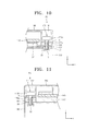
- FIGS. 10 and 11 are detailed cross-sectional views of shock absorbing layers 181 and 182 that are arranged at ends E1 and E2 of an upper cover 160, respectively.
- each of the coupling members 171 and 172 may include an axis part 170a extending in a longitudinal direction, and a head part 170b extending from an end of the axis part 170a and extending in a radial direction.
- screw threads may be formed in an outer surface of the axis part 170a.
- Through holes 161 and 162 for having the coupling members 171 and 172 inserted therein are formed in the upper cover 160.
- first and second through holes 161 and 162 for having first and second coupling members 171 and 172 inserted therein may be formed in the ends E1 and E2 of the upper cover 160.
- the through holes 161 and 162 may penetrate an entire thickness of the upper cover 160.
- the through holes 161 and 162 may have cylindrical forms, and may have inner diameters sufficient to receive the coupling members 171 and 172, respectively.
- the through holes 161 and 162 may form mount portions S, each having a stepped shape and stepped inward in a radial direction.
- the mount portion S functions as a stopper that defines a position of each of the coupling members 171 and 172, and the coupling members 171 and 172 are inserted so that the head part 170b of each of the coupling members 171 and 172 is arranged to contact an upper surface of the mount portion S, and the mount portion S firmly supports the head part 170b of each of the coupling members 171 and 172.
- the coupling grooves 31 and 32 may be formed at sides of the bare cell 100.
- the coupling grooves 31 and 32 may be formed at sides of a cap plate 30, and may be open toward the upper cover 160 that faces the cap plate 30.
- the coupling grooves 31 and 32 may include a first coupling groove 31 formed at the side of the bare cell 100, and a second coupling groove 32 formed at the other side of the bare cell 100.
- the coupling grooves 31 and 32 may be coupled with the coupling members 171 and 172 that penetrate the upper cover 160 and extend to contact the cap plate 30, and may form a coupling by receiving ends of the coupling members 171 and 172.
- the coupling grooves 31 and 32 may have a shape that extends downward from a top surface of the cap plate 30 and has a predetermined depth, and screw threads (not shown) may be formed at inner walls of the coupling grooves 31 and 32 so as to form the coupling with the coupling members 171 and 172.
- the coupling members 171 and 172 are inserted into the through holes 161 and 162 of the upper cover 160, penetrate the upper cover 160, and then are coupled with the coupling grooves 31 and 32 of the bare cell 100.
- the coupling members 171 and 172 are coupled in a manner that the head part 170b of each of the coupling members 171 and 172 is supported by the mount portion S of the upper cover 160, while the axis part 170a that extends from the head part 170b is coupled with each of the coupling grooves 31 and 32.
- the head part 170b of each of the coupling members 171 and 172 is adhered to the mount portion S of the upper cover 160, the axis parts 170a of the coupling members 171 and 172 are fixed in the coupling grooves 31 and 32 of the bare cell 100, and the coupling members 171 and 172 couple the upper cover 160 and the bare cell 100 by using the head part 170b and the axis part 170a.
- the mount portion S to which the head part 170b of each of the coupling members 171 and 172 is adhered is arranged as a part of the upper cover 160, and shock absorbing layers 181 and 182 are formed in a lower portion of the mount portion S, that is, between the mount portion S and the bare cell 100.
- the shock absorbing layers 181 and 182 may be arranged to directly contact the bare cell 100, or may be arranged to directly contact a lead member 132 on the bare cell 100.
- the first shock absorbing layer 181 arranged at the first end E1 of the upper cover 160 contacts the lead member 132 on the bare cell 100
- the second shock absorbing layer 182 arranged at the second end E2 of the upper cover 160 contacts the bare cell 100.
- the upper cover 160 is formed of a first material that is relatively hard, and the shock absorbing layers 181 and 182 are formed of a second material that is relatively soft.
- the mount portion S By forming the mount portion S by using the hard first material (corresponding to the upper cover 160), wherein the head part 170b of each of the coupling members 171 and 172 is in press contact with the mount portion S, the mount portion S may firmly support the coupling members 171 and 172, in spite of a locally-condensed pressure.
- the soft second material corresponding to the shock absorbing layers 181 and 182
- the shock absorbing layers 181 and 182 that are pressed by a pressurized coupling force of the coupling members 171 and 172 may be interposed between the upper cover 160 and the bare cell 100.
- the shock absorbing layers 181 and 182 that have a first thickness t1 before the coupling with the coupling members 171 and 172 may be pressed to have a second thickness t2 after the coupling with the coupling members 171 and 172 (here, t1 > t2), and due to the pressurized coupling force of the coupling members 171 and 172, the shock absorbing layers 181 and 182 may maintain their pressed status between the upper cover 160 and the bare cell 100.
- the elastic resilience of the shock absorbing layers 181 and 182 works between the upper cover 160 and the bare cell 100, and the elastic resilience may form an elastic bias in a direction in which the head part 170b of the coupling member 171, and the lead member 132 are pushed in opposite directions.
- the lead member 132 may be elastically biased on the bare cell 100, and connection resistance between the lead member 132 and the bare cell 100 may be reduced.
- the lead member 132 is elastically biased on the bare cell 100, it is possible to prevent an increase of the connection resistance, in spite of an external shock.
- each of the coupling members 171 and 172 is elastically biased in a direction distant from the bare cell 100, decoupling of the coupling members 171 and 172 is prevented, and coupling between the upper cover 160 and the bare cell 100 is improved, so that the lead member 132 interposed between the upper cover 160 and the bare cell 100 is firmly fixed, and the connection resistance is not increased, in spite of the external shock.
- the first shock absorbing layer 181 arranged at the first end E1 of the upper cover 160 contacts the lead member 132 on the bare cell 100
- the second shock absorbing layer 182 arranged at the second end E2 of the upper cover 160 contacts the bare cell 100.
- the present invention is not limited thereto, and thus, for example, all of the first and second shock absorbing layers 181 and 182 may contact the lead member 132 on the bare cell 100, or may contact the bare cell 100.
- the lead member 132 is arranged on only one end of the bare cell 100.
- the lead members 132 may be arranged on both ends of the bare cell 100, and the first and second shock absorbing layers 181 and 182 may be arranged on the lead members 132.
- the first shock absorbing layer 181 arranged at the first end E1 of the upper cover 160 completely contacts the lead members 132.
- this complete contact is only an example, and thus, in another embodiment, a portion of the first shock absorbing layer 181 may contact the lead members 132 while the other portion of the first shock absorbing layer 181 may contact the bare cell 100 that does not have the lead members 132 arranged thereon.
- the first and second shock absorbing layers 181 and 182 are formed at the ends E1 and E2 of the upper cover 160.
- the first and second shock absorbing layers 181 and 182 may be formed at a selected end of the upper cover 160.
- the first shock absorbing layer 181 may be arranged at the first end E1 at which the lead members 132 is disposed, so that connection resistance of the lead members 132 is reduced, but the second shock absorbing layer 182 may not be formed at the second end E2 so that the manufacturing costs or manufacturing processes may be reduced.
- the manufacturing costs or manufacturing processes may not be sharply changed according to the number of the shock absorbing layers 181 and 182.
- Table 1 shows the result of a free fall test for demonstrating an effect of the one or more embodiments of the present invention.
- a battery pack according to the one or more embodiments of the present invention has the structure of FIG. 1 .
- a comparative example is compared to the battery pack according to the one or more embodiments of the present invention, and the comparative example and the battery pack are different from each other in that the comparative example does not include a shock absorbing layer.
- a resistance value IR was obtained by measuring resistance of a current path between a positive electrode and a negative electrode of the external connection terminal 145. With respect to each sample, the free fall test was repeated 50 times, 100 times, 150 times, 200 times, and 250 times and variation of the resistance according to the free fall was measured. [Table 1] No.
- a resistance increase of about 18% and 30% is measured after 250 times of free fall.
- a resistance increase of about 4% and 7% is measured after 250 times of free fall.
- connection resistance among configuring elements that form a current path is increased, such that a resistance increase occurs.
- the resistance increase in the battery pack is smaller than the comparative example, and this is because shock absorbing layer 181 and 182 of the battery pack absorb a falling shock so that structural damage of a lead member and an upper portion of a bare cell 100 contacting the lead member 132 is prevented, and an increase of connection resistance between the lead member 132 and the bare cell 100 is restrained.
Landscapes
- Chemical & Material Sciences (AREA)
- Chemical Kinetics & Catalysis (AREA)
- Electrochemistry (AREA)
- General Chemical & Material Sciences (AREA)
- Engineering & Computer Science (AREA)
- Manufacturing & Machinery (AREA)
- Microelectronics & Electronic Packaging (AREA)
- Battery Mounting, Suspending (AREA)
- Connection Of Batteries Or Terminals (AREA)
Abstract
Description
- There is increasing demand for using a secondary battery as an energy source for mobile devices such as mobile phones, notebooks, and the like. Recently, as a substitute energy source for replacing fossil fuels, secondary batteries are studied and developed to be used in electric vehicles and hybrid vehicles.
- In general, a secondary battery includes an inflammable material, and in consideration of the stability of the secondary battery, the secondary battery has a circuit for efficiently controlling abnormal operation states including overcharge, overdischarge, overcurrent, and the like. Also, the secondary battery is used in the form of a battery pack having a cover so as to protect the circuit from an external environment.
- Recently, due to an increase in use of mobile devices, increasing the capacity of the battery pack while retaining the same volume has become increasingly important. However, reliability conditions for verifying the battery pack are the same as before.
- When weight and volume of a battery pack are increased, the characteristic that deteriorates most from among the reliability conditions is a falling characteristic, ie. the characteristic that defines the result of the battery falling or being dropped. This is because a shock resulting from a fall is increased according to an increase in the weight or volume of the battery pack. This causal relationship severely damages the battery pack in a free fall test, the biggest problem being that resistance of a charge-discharge path, which directly affects efficiency of the battery pack, is increased.
- One or more embodiments of the present invention include a battery pack which has increased reliability with respect to an external shock.
- One or more embodiments of the present invention include a battery pack in which electric resistance of a charge-discharge path remains at a low level, in spite of an external shock.
- According to the invention, there is provided a battery pack comprising a bare cell including a cap plate, a protection circuit module mounted to the cap plate and cover means mounted to the cap plate for covering the protection circuit module, wherein the cover means comprises side wall portions and end portions at respective ends of the sidewall portions, wherein the side wall portions comprise a first material and one or both of the end portions comprise a resilient end portion, the resilient end portion comprising a second material that is more resilient than the first material.
- By including a resilient end portion at one or both ends of the cover, either separately from or as part of the cover, shock transmitted when the cover hits a surface can be more efficiently absorbed.
- The side wall portions and the end portions may together provide a substantially continuous surface to be mounted to the cap plate.
- The cover means may comprise a cover having a top portion and the side wall portions may comprise first and second side wall portions extending from the top portion.
- The cover means may comprise a cover and at least one resilient end portion separate from the cover. The cover may comprise a cut-out portion for accommodating the or each resilient end portion.
- The cover means may comprise a cover in which the or each resilient end portion is integrally formed with the side wall portions.
- The top portion and the side wall portions may be formed of the same first material.
- The or each resilient end portion may further comprise a hole for receiving a coupling member that couples the cover means to the bare cell. The or each resilient end portion may comprise a first portion surrounding the hole and planar portions extending from the first portion to meet the side wall portions.
- The battery pack may further comprise a lead member for connecting the cap plate to the protection circuit module, wherein at least one of the resilient end portions is disposed on the lead member.
- By disposing the resilient end portion on the lead member, the lead member is protected from external shock.
- The or each resilient end portion may be compressed by the cover means so as to bias the lead member against the cap plate. The lead member is both protected by the resilient portion and the resilient portion assists in pressing the lead member against the cap plate so as to maintain a good electrical contact, even when the battery pack is dropped.
- The or each resilient end portion may be disposed between a mounting portion of the cover means that supports the coupling member and the lead member.
- The lead member and the or each resilient end portion may extend to the edge of the cap plate.
- The first and second resilient end portions may have the same thickness, wherein the first resilient end portion is disposed on the lead member and the second resilient end portion is disposed on the cap plate. The resilience of the end portions allows the same portion to be used irrespective of whether it rests on the lead member or just on the cap plate, so saving manufacturing cost.
- The cover means may comprise a single resilient end portion disposed on the lead member. In this case, a single resilient end portion may be used where its protection is most effective.
- These and/or other aspects will become apparent and more readily appreciated from the following description of the embodiments, taken in conjunction with the accompanying drawings, in which:
-
FIGS. 1 to 3 are exploded perspective views of a battery pack according to an embodiment of the present invention; -
FIG. 4 is a perspective view of a battery pack according to another embodiment of the present invention; -
FIG. 5 is a detailed perspective view of a first shock absorbing layer arranged at a first end of an upper cover; -
FIG. 6 is a detailed perspective view of a second shock absorbing layer arranged at a second end of the upper cover; -
FIG. 7 is a perspective view of a battery pack according to a comparative example; -
FIGS. 8 and 9 are cross-sectional views of the battery pack ofFIG. 1 ; -
FIG. 10 is a detailed cross-sectional view of a first shock absorbing layer; and -
FIG. 11 is a detailed cross-sectional view of a second shock absorbing layer. -
FIGS. 1 to 3 are exploded perspective views of a battery pack according to an embodiment of the present invention. - The battery pack includes a
bare cell 100 capable of being charged and discharged, a protective circuit module (PCM) 150 mounted on thebare cell 100 so as to control charging and discharging operations of thebare cell 100, and anupper cover 160 coupled with thebare cell 100 so as to receive thePCM 150. - The
bare cell 100 is a rechargeable, secondary battery, which may be formed of a lithium-ion battery, and has a structure in which an electrode assembly 10 including apositive electrode plate 11, anegative electrode plate 13, and a separator 15 is impregnated with an electrolyte (not shown) and then sealed in acan 20. For example, thebare cell 100 includes the electrode assembly 10 in the shape of a jelly roll formed by rolling thepositive electrode plate 11, thenegative electrode plate 13, and the separator 15; the can 20 having an opening at its top surface so as to receive the electrode assembly 10 and the electrolyte; and acap plate 30 for sealing the opening of thecan 20. A contact between thecap plate 30 and thecan 20 may be laser-welded to form a sealed combination. - At least one of the
positive electrode plate 11 and thenegative electrode plate 13 may be connected to apositive electrode tab 17 and anegative electrode tab 19. For example, thepositive electrode tab 17 may be connected to thecap plate 30, and thenegative electrode tab 19 may be connected to anelectrode terminal 35 that projects upwardly from thecap plate 30. Theelectrode terminal 35 is coupled with but insulated from thecap plate 30, and projects upwardly from thecap plate 30. - The PCM 150 functions to control the charging and discharging operations of the
bare cell 100, and when overcurrent greater than a threshold value flows, when a temperature of thebare cell 100 exceeds a predetermined value, or when overcharge or overdischarge occurs, thePCM 150 blocks electric connection and performs a protective operation for protecting thebare cell 100. For example, thePCM 150 may include acircuit substrate 140 having a sensing circuit (not shown) for detecting state information regarding a current, a voltage, and the like, and a charge-discharge protective circuit (not shown), and a protectingdevice 120 connected to thecircuit substrate 140 and restricting a charge-discharge current according to a rise in temperature. - The
circuit substrate 140 may be formed of a printed circuit board (PCB) that includes a wire pattern (not shown) so as to form a charge-discharge current path between an external device (not shown) and thebare cell 100, and includes a protective circuit (not shown). Anexternal connection terminal 145 for relaying electrical connection with the external device (not shown) may be arranged on thecircuit substrate 140. - The
protecting device 120 forms a current path between theelectrode terminal 35 of thecap plate 30 and thecircuit substrate 140. When the temperature of thebare cell 100 exceeds a predetermined threshold value, the protectingdevice 120 functions to forcibly decrease the charge-discharge current by increasing electrical resistance. The protectingdevice 120 may include a positive temperature coefficient (PTC) device or a temperature fuse. In a case where the protectingdevice 120 is formed as the PTC device, thePTC protecting device 120 may include avariable resistor 120c of which electric resistance value varies according to a temperature, and first and second connectingmembers 120a and 120b that are connected to thevariable resistor 120c and extend in opposite directions. For example, the first connectingmember 120a is connected to theelectrode terminal 35 of thecap plate 30, while the second connecting member 120b is connected to thecircuit substrate 140. - The
positive electrode tab 17 and thenegative electrode tab 19 of thebare cell 100 are electrically connected to electrode pads (not shown) of thecircuit substrate 140, respectively. For example, thenegative electrode tab 19 of thebare cell 100 may be connected to a first electrode pad (not shown) of thecircuit substrate 140 via theelectrode terminal 35 and the protectingdevice 120, and thepositive electrode tab 17 of thebare cell 100 may be connected to a second electrode pad (not shown) of thecircuit substrate 140 via thecap plate 30 and alead member 132. Thelead member 132 may have a stepped form that is bent to have upper and lower portions that are stepped with respect to each other, and the upper portion may be connected to thecircuit substrate 140 and the lower portion may extend to contact a top surface of thecap plate 30. Thelead member 132 may be soldered to the second electrode pad (not shown) of thecircuit substrate 140. Also, thelead member 132 may be fixed on thecap plate 30 by using acoupling member 171, and for this coupling, a throughhole 131 for insertion of thecoupling member 171 may be formed in thelead member 132. - Insulating
members bare cell 100. For example, theinsulating members member 111 formed to surround theelectrode terminal 35, and a secondinsulating member 112 interposed between thecap plate 30 and thecircuit substrate 140. The insulatingmembers PCM 150 on thebare cell 100, and to prevent an electrical short between thebare cell 100 and thePCM 150. Also, the insulatingmembers PCM 150 and thebare cell 100, and to absorb a shock. Meanwhile, another insulatingmember 113 may be disposed between the protectingdevice 120 and thecap plate 30. - The
upper cover 160 is coupled thebare cell 100 so as to receive thePCM 150. A terminal hole 160' of an opening pattern may be formed in theupper cover 160 so as to expose theexternal connection terminal 145, and to allow access with the external device (not shown). - An
insulating label sheet 199 having an adhesive coated thereon may be adhered to an outer surface of thebare cell 100. An adheringmember 193 such as a double-sided adhesive tape is arranged on a bottom of thebare cell 100 so that alower cover 195 may be coupled thereto. Meanwhile, areference numeral 190 ofFIG. 1 indicates plug members that cover throughholes coupling members - Referring to
FIG. 3 ,shock absorbing layers upper cover 160. For example, theshock absorbing layers upper cover 160, and may include a firstshock absorbing layer 181 arranged at a first end E1, and a secondshock absorbing layer 182 arranged at a second end E2. - The
shock absorbing layers upper cover 160 facing thebare cell 100. Theshock absorbing layers upper cover 160 to which theshock absorbing layers - The
shock absorbing layers upper cover 160, and any flexible material will do as long as the flexible material is more flexible than theupper cover 160 and is capable of absorbing an external shock. For example, theupper cover 160 may be formed of a polycarbonate material, and theshock absorbing layers upper cover 160. However, the material for forming theshock absorbing layers - The
shock absorbing layers upper cover 160 in an injection-moulded manner. For example, theshock absorbing layers upper cover 160 via one injection-moulding process. In this regard, theupper cover 160 may be formed from a first material (e.g., polycarbonate) that is inserted into an injection-mould frame (not shown), and theshock absorbing layers upper cover 160 may be formed from a second material (e.g., a rubber-based or silicon-based material) that is inserted after the first material. Here, the second material fills an insertion space that is defined by theupper cover 160, is hardened to have a form that is fit for theupper cover 160, and forms theshock absorbing layers upper cover 160. However, the formation of theshock absorbing layers - Referring to
FIG. 4 ,shock absorbing layers upper cover 160. For example, theshock absorbing layers upper cover 160. Theshock absorbing layers upper cover 160 but may be formed via separate processes and then may be coupled to theupper cover 160. Theshock absorbing layers upper cover 160 may be fixed on thecap plate 30 by using thecoupling members cap plate 30 via theupper cover 160. Reference numerals 181' and 182' ofFIG. 4 indicate through holes that are formed in theshock absorbing layers coupling members upper cover 160 and theshock absorbing layers upper cover 160 and theshock absorbing layers - The
shock absorbing layers upper cover 160 and thebare cell 100, and provide elastic support between theupper cover 160 and thebare cell 100. Theshock absorbing layers bare cell 100 by absorbing or relieving a shock from theupper cover 160. For example, theshock absorbing layers bare cell 100 which may occur when theupper cover 160 hits thebare cell 100 due to a falling shock of the battery pack. - The
upper cover 160 and thebare cell 100 may be coupled to each other by using thecoupling members FIG. 1 , thecoupling members coupling grooves bare cell 100 via the throughholes upper cover 160. Here, thecoupling members second coupling members upper cover 160, respectively. For example, thefirst coupling member 171 may be coupled with thefirst coupling groove 31 of thecap plate 30 via the throughhole 131 that is formed in thelead member 132 that extend to contact thecap plate 30. The throughhole 131 of thelead member 132, and thefirst coupling groove 31 of thecap plate 30 are aligned with respect to each other, and thefirst coupling member 171 is coupled to thecap plate 30 via the throughhole 131. Meanwhile, thesecond coupling member 172 may be coupled with thesecond coupling groove 32 of thecap plate 30. The first andsecond coupling grooves coupling members - The
cover 160 has a stepped portion at a lower part thereof, as shown inFigure 1 , the lower side wall of the cover being thinner than the side wall of the upper part of the cover and forming a continuous outer surface with theresilient end portions insulating label sheet 199. In other words, the insulatinglabel sheet 199 wraps around both the bare cell and the continuous outer surface formed by the lower side walls and the resilient end portions, as shown inFigures 9 to 11 . -
FIG. 5 is a detailed perspective view of the firstshock absorbing layer 181 arranged at the first end E1 of theupper cover 160. Referring toFIG. 5 , thecircuit substrate 140 is arranged on thecap plate 30, and thelead member 132 that is connected to thecircuit substrate 140 extends to contact thecap plate 30. Theupper cover 160 is coupled to thecap plate 30 so as to receive thecircuit substrate 140. The firstshock absorbing layer 181 is arranged in a lower portion of theupper cover 160 so as to face thelead member 132 and thecap plate 30. Thefirst coupling member 171 that is inserted into the throughhole 161 of theupper cover 160 is coupled with thecoupling groove 31 on thecap plate 30 via the throughhole 131 of thelead member 132. - The first
shock absorbing layer 181 provides elastic support between theupper cover 160 and thelead member 132, and absorbs a shock therebetween. By doing so, the firstshock absorbing layer 181 prevents damage to or structural deformation of thelead member 132 and/or thebare cell 100, and maintains low connection resistance between thelead member 132 and thebare cell 100. - For example, when the battery pack has fallen, a strong external shock may be applied to the
upper cover 160. In a case where an external shock F0 is applied to an end E1 of theupper cover 160, the external shock F0 may be sequentially conveyed to thelead member 132 and thebare cell 100 which are in a close contact. Here, the firstshock absorbing layer 181, which is interposed between theupper cover 160 and thelead member 132, intervenes in a shock conveyance procedure and then absorbs or relieves the external shock F0, so that shocks F1 and F2 that are applied to thelead member 132 and/or thebare cell 100 may be sharply reduced, and the damage to or the structural deformation of thelead member 132 and/or thebare cell 100 due to the external shock F0 may be prevented. - The
lead member 132 that forms a current path between thecircuit substrate 140 and thebare cell 100 may be in a close contact on thebare cell 100 by a pressure of thefirst coupling member 171 so as to maintain low resistance. When an interface between thelead member 132 and thebare cell 100 is deformed by the external shock F0, a contact status between thelead member 132 and thebare cell 100 is spoiled such that connection resistance is increased, and the increase of the connection resistance deteriorates the charge-discharge efficiency of the battery pack. - The
upper cover 160 is assembled in a manner that the firstshock absorbing layer 181 is interposed on thelead member 132 that is arranged on thebare cell 100, so that it is possible to prevent damage to thelead member 132 or thebare cell 100 due to the shocks F1 and F2 from theupper cover 160, and to efficiently prevent an increase of connection resistance due to deformation of thelead member 132 and thebare cell 100. -
FIG. 6 is a detailed perspective view of the secondshock absorbing layer 182 arranged at the second end E2 of theupper cover 160. Referring toFIG. 6 , thecircuit substrate 140 is arranged on thecap plate 30, and theupper cover 160 is coupled on thecap plate 30 so as to receive thecircuit substrate 140. The secondshock absorbing layer 182 is arranged at a lower portion of theupper cover 160 so as to face thecap plate 30. Thesecond coupling member 172 that is inserted into the throughhole 162 of theupper cover 160 is coupled with thecoupling groove 32 in thecap plate 30. - The second
shock absorbing layer 182 provides elastic support between theupper cover 160 and thebare cell 100, and absorbs a shock therebetween, so that the secondshock absorbing layer 182 prevents damage or structural deformation of thebare cell 100. For example, when the battery pack has fallen, a strong external shock may be applied to theupper cover 160. In a case where an external shock F0' is applied to the second end E2 of theupper cover 160, the external shock F0' may be conveyed to thebare cell 100 that is in a close contact with theupper cover 160. Here, the secondshock absorbing layer 182, which is interposed between theupper cover 160 and thebare cell 100, intervenes in a shock conveyance procedure and then absorbs or relieves the external shock F0', so that a shock F1' that is applied to thebare cell 100 may be sharply reduced, and a damage or deformation of thebare cell 100 due to the external shock F0' may be prevented. -
FIG. 7 is a perspective view of a battery pack according to a comparative example. Referring toFIG. 7 , anupper cover 260 is assembled so as to contact alead member 232 on abare cell 200, and a shock absorbing member is not arranged between theupper cover 260 and thelead member 232. In the battery pack ofFIG. 7 , theupper cover 260 receives an external shock F0" and then hits thelead member 232 and thebare cell 200. Due to shocks F1" and F2", thelead member 232 and/or thebare cell 200 are damaged and deformed, such that thelead member 232 may not maintain its firm contact on thebare cell 200, or a gap is formed between thelead member 232 and thebare cell 200. Thus, connection resistance between thebare cell 200 and a circuit substrate via thelead member 232 is increased, or in the worst case, a current path is cut. - For example, the
upper cover 260 and thebare cell 200 may be formed of a plastic material and an aluminium material, respectively, which are hard materials having a small shock absorbing characteristic. Thus, there is a high possibility that theupper cover 260 and thebare cell 200 may damage each other due to a shock at a contact surface between theupper cover 260 and thebare cell 200. In this regard, when a repetitive shock such as a falling shock is applied, there is a high possibility that an upper portion of thebare cell 200 having a relatively small hardness will be damaged. - Meanwhile, a
coupling member 270 is coupled with acoupling groove 235 in thebare cell 200 via a throughhole 261 of theupper cover 260 and a throughhole 231 of thelead member 232. A cylindricalhollow structure 260a for guiding thecoupling member 270 may be arranged in theupper cover 260. If the cylindricalhollow structure 260a directly hits thelead member 232 and/or thebare cell 200, there is a high possibility that direct-under areas R1 and R2 of thelead member 232 and thebare cell 200 will be damaged. - Also, since the
coupling groove 235 for fixing an end of thecoupling member 270 is deformed with thebare cell 200, thecoupling member 270 does not provide an appropriate pressurized coupling force between theupper cover 260 and thebare cell 200, such that thelead member 232 may not be sufficiently coupled to thebare cell 200, or thecoupling member 270 is decoupled and then thelead member 232 may be detached from thebare cell 200. As a result, connection resistance between a circuit substrate and thebare cell 200 is increased, which deteriorates the charge-discharge efficiency of the battery pack. - In the battery pack of
FIG. 5 , the firstshock absorbing layer 181 is interposed between theupper cover 160 and thelead member 132 which are in a close contact, so that it is possible to prevent the damage to thelead member 132 and thebare cell 100, and to maintain the connection resistance of thelead member 132 at a low level. - Also, in the battery pack of
FIG. 5 , the firstshock absorbing layer 181 is arranged to protect thebare cell 100 by absorbing the shocks F1 and F2 that are applied to thelead member 132 and thebare cell 100, so that it is possible to prevent damage and deformation of thebare cell 100, and to prevent an increase of the connection resistance that is caused by the deformation of thebare cell 100. That is, in the battery pack ofFIG. 5 , in spite of the external shock F0, the connection resistance between thelead member 132 and thebare cell 100 is not increased. - Due to a pressurized coupling force of the
coupling member 171, the firstshock absorbing layer 181 may be coupled in a pressed status, and elastic resilience of the firstshock absorbing layer 181 may form an elastic bias in a direction in which thecoupling member 171 and thelead member 132 are pushed in opposite directions. Accordingly, thelead member 132 is pressed onto thebare cell 100, so that the connection resistance of thelead member 132 is reduced, and the connection resistance is not increased, in spite of the external shock F0. Also, decoupling of thecoupling member 171 is prevented, and coupling between theupper cover 160 and thebare cell 100 is improved, so that thelead member 132 interposed between theupper cover 160 and thebare cell 100 is firmly fixed, and the connection resistance is not increased, in spite of the external shock F0. -
FIGS. 8 and 9 are cross-sectional views of the battery pack ofFIG. 1 .FIGS. 10 and 11 are detailed cross-sectional views ofshock absorbing layers upper cover 160, respectively. - Referring to
FIGS. 8 through 11 , theupper cover 160 and abare cell 100 may be coupled to each other viacoupling members coupling members upper cover 160 and then are coupled withcoupling grooves bare cell 100. For example, each of thecoupling members axis part 170a extending in a longitudinal direction, and ahead part 170b extending from an end of theaxis part 170a and extending in a radial direction. For coupling with thecoupling grooves axis part 170a. - Through
holes coupling members upper cover 160. For example, first and second throughholes second coupling members upper cover 160. - The through
holes upper cover 160. For example, the throughholes coupling members holes coupling members coupling members head part 170b of each of thecoupling members head part 170b of each of thecoupling members - The
coupling grooves bare cell 100. Thecoupling grooves cap plate 30, and may be open toward theupper cover 160 that faces thecap plate 30. Thecoupling grooves first coupling groove 31 formed at the side of thebare cell 100, and asecond coupling groove 32 formed at the other side of thebare cell 100. - The
coupling grooves coupling members upper cover 160 and extend to contact thecap plate 30, and may form a coupling by receiving ends of thecoupling members coupling grooves cap plate 30 and has a predetermined depth, and screw threads (not shown) may be formed at inner walls of thecoupling grooves coupling members - The
coupling members holes upper cover 160, penetrate theupper cover 160, and then are coupled with thecoupling grooves bare cell 100. Thecoupling members head part 170b of each of thecoupling members upper cover 160, while theaxis part 170a that extends from thehead part 170b is coupled with each of thecoupling grooves head part 170b of each of thecoupling members upper cover 160, theaxis parts 170a of thecoupling members coupling grooves bare cell 100, and thecoupling members upper cover 160 and thebare cell 100 by using thehead part 170b and theaxis part 170a. - The mount portion S to which the
head part 170b of each of thecoupling members upper cover 160, andshock absorbing layers bare cell 100. Theshock absorbing layers bare cell 100, or may be arranged to directly contact alead member 132 on thebare cell 100. For example, the firstshock absorbing layer 181 arranged at the first end E1 of theupper cover 160 contacts thelead member 132 on thebare cell 100, and the secondshock absorbing layer 182 arranged at the second end E2 of theupper cover 160 contacts thebare cell 100. - The
upper cover 160 is formed of a first material that is relatively hard, and theshock absorbing layers head part 170b of each of thecoupling members coupling members shock absorbing layers 181 and 182) between the mount portion S and thebare cell 100, a pressure conveyance between the mount portion S and thebare cell 100 may be efficiently absorbed due to elastic transformation. - Referring to
FIGS. 8 and 9 , theshock absorbing layers coupling members upper cover 160 and thebare cell 100. For example, theshock absorbing layers coupling members coupling members 171 and 172 (here, t1 > t2), and due to the pressurized coupling force of thecoupling members shock absorbing layers upper cover 160 and thebare cell 100. Accordingly, elastic resilience of theshock absorbing layers upper cover 160 and thebare cell 100, and the elastic resilience may form an elastic bias in a direction in which thehead part 170b of thecoupling member 171, and thelead member 132 are pushed in opposite directions. Thus, thelead member 132 may be elastically biased on thebare cell 100, and connection resistance between thelead member 132 and thebare cell 100 may be reduced. Also, since thelead member 132 is elastically biased on thebare cell 100, it is possible to prevent an increase of the connection resistance, in spite of an external shock. - Also, since the
head part 170b of each of thecoupling members bare cell 100, decoupling of thecoupling members upper cover 160 and thebare cell 100 is improved, so that thelead member 132 interposed between theupper cover 160 and thebare cell 100 is firmly fixed, and the connection resistance is not increased, in spite of the external shock. - In the battery pack of
FIG. 1 , the firstshock absorbing layer 181 arranged at the first end E1 of theupper cover 160 contacts thelead member 132 on thebare cell 100, and the secondshock absorbing layer 182 arranged at the second end E2 of theupper cover 160 contacts thebare cell 100. However, the present invention is not limited thereto, and thus, for example, all of the first and secondshock absorbing layers lead member 132 on thebare cell 100, or may contact thebare cell 100. - For example, in the battery pack of
FIG. 1 , thelead member 132 is arranged on only one end of thebare cell 100. However, in order to improve electric connection between thecircuit substrate 140 and thebare cell 100, thelead members 132 may be arranged on both ends of thebare cell 100, and the first and secondshock absorbing layers lead members 132. - For example, in the battery pack of
FIG. 1 , the firstshock absorbing layer 181 arranged at the first end E1 of theupper cover 160 completely contacts thelead members 132. However, this complete contact is only an example, and thus, in another embodiment, a portion of the firstshock absorbing layer 181 may contact thelead members 132 while the other portion of the firstshock absorbing layer 181 may contact thebare cell 100 that does not have thelead members 132 arranged thereon. - In the battery pack of
FIG. 1 , the first and secondshock absorbing layers upper cover 160. However, the first and secondshock absorbing layers upper cover 160. For example, the firstshock absorbing layer 181 may be arranged at the first end E1 at which thelead members 132 is disposed, so that connection resistance of thelead members 132 is reduced, but the secondshock absorbing layer 182 may not be formed at the second end E2 so that the manufacturing costs or manufacturing processes may be reduced. However, in a case where theshock absorbing layers upper cover 160 via one injection-moulding process, the manufacturing costs or manufacturing processes may not be sharply changed according to the number of theshock absorbing layers - Table 1 shows the result of a free fall test for demonstrating an effect of the one or more embodiments of the present invention.
- A battery pack according to the one or more embodiments of the present invention has the structure of
FIG. 1 . A comparative example is compared to the battery pack according to the one or more embodiments of the present invention, and the comparative example and the battery pack are different from each other in that the comparative example does not include a shock absorbing layer. A resistance value IR was obtained by measuring resistance of a current path between a positive electrode and a negative electrode of theexternal connection terminal 145. With respect to each sample, the free fall test was repeated 50 times, 100 times, 150 times, 200 times, and 250 times and variation of the resistance according to the free fall was measured.[Table 1] No. Before drops After 50 drops After 100 drops After 150 drops After 200 drops After 250 drops IR(mohm) IR(mohm) IR(mohm) IR(mohm) IR(mohm) IR(mohm) comparative
example1 115 114 116 125 126 136 2 113 115 120 122 127 147 present
invention3 115 115 115 116 119 120 4 116 116 117 120 121 124 - In
sample 1 and sample 2 corresponding to the comparative example, a resistance increase of about 18% and 30% is measured after 250 times of free fall. However, in sample 3 and sample 4 corresponding to the present invention, a resistance increase of about 4% and 7% is measured after 250 times of free fall. - When the number of drops increases, connection resistance among configuring elements that form a current path is increased, such that a resistance increase occurs. In this regard, the resistance increase in the battery pack is smaller than the comparative example, and this is because
shock absorbing layer bare cell 100 contacting thelead member 132 is prevented, and an increase of connection resistance between thelead member 132 and thebare cell 100 is restrained. - It should be understood that the exemplary embodiments described herein should be considered in a descriptive sense only and not for purposes of limitation. Descriptions of features or aspects within each embodiment should typically be considered as available for other similar features or aspects in other embodiments.
Claims (15)
- A battery pack comprising:a bare cell (100) including a cap plate (30);a protection circuit module (150) mounted to the cap plate; andcover means (160) mounted to the cap plate for covering the protection circuit module, wherein the cover means comprises side wall portions and end portions (181, 182) at respective ends of the sidewall portions, wherein the side wall portions comprise a first material and one or both of the end portions comprise a resilient end portion, the resilient end portion comprising a second material that is more resilient than the first material.
- The battery pack of claim 1, wherein the side wall portions and the end portions together provide a substantially continuous surface to be mounted to the cap plate.
- The battery pack of claim 1 or 2, wherein the cover means comprises a cover having a top portion and the side wall portions comprise first and second side wall portions extending from the top portion.
- The battery pack of claim 1, 2 or 3, wherein the cover means comprises a cover and at least one resilient end portion separate from the cover.
- The battery pack of claim 4, wherein the cover comprises a cut-out portion for accommodating the or each resilient end portion.
- The battery pack of claim 1, 2 or 3, wherein the cover means comprises a cover in which the or each resilient end portion is integrally formed with the side wall portions.
- The battery pack of any one of claims 3 to 6, wherein the top portion and the side wall portions are formed of the same first material.
- The battery pack of any one of the preceding claims, wherein the or each resilient end portion further comprises a hole (181', 182') for receiving a coupling member (171, 172) that couples the cover means to the bare cell.
- The battery pack of claim 8, wherein the or each resilient end portion comprises a first portion surrounding the hole and planar portions extending from the first portion to meet the side wall portions.
- The battery pack of any one of the preceding claims, further comprising a lead member (132) for connecting the cap plate to the protection circuit module (150), wherein at least one of the resilient end portions is disposed on the lead member.
- The battery pack of claim 10, wherein the or each resilient end portion is compressed by the cover means so as to bias the lead member (132) against the cap plate.
- The battery pack of claim 10 or 11, when dependent on claim 8, wherein the or each resilient end portion is disposed between a mounting portion (S) of the cover means that supports the coupling member and the lead member.
- The battery pack of claim 10, 11 or 12, wherein the lead member and the or each resilient end portion extend to the edge of the cap plate.
- The battery pack of any one of claims 10 to 13, comprising first and second resilient end portions having the same thickness, wherein the first resilient end portion (181) is disposed on the lead member (132) and the second resilient end portion (182) is disposed on the cap plate.
- The battery pack of any one of claims 10 to 14, wherein the cover means comprises a single resilient end portion disposed on the lead member (132).
Applications Claiming Priority (2)
| Application Number | Priority Date | Filing Date | Title |
|---|---|---|---|
| US37788510P | 2010-08-27 | 2010-08-27 | |
| US13/080,635 US9818990B2 (en) | 2010-08-27 | 2011-04-05 | Battery pack with shock absorber |
Publications (2)
| Publication Number | Publication Date |
|---|---|
| EP2423997A1 true EP2423997A1 (en) | 2012-02-29 |
| EP2423997B1 EP2423997B1 (en) | 2017-08-02 |
Family
ID=45034227
Family Applications (1)
| Application Number | Title | Priority Date | Filing Date |
|---|---|---|---|
| EP11170500.0A Not-in-force EP2423997B1 (en) | 2010-08-27 | 2011-06-20 | Battery pack comprising a cover with a resilient material |
Country Status (5)
| Country | Link |
|---|---|
| US (1) | US9818990B2 (en) |
| EP (1) | EP2423997B1 (en) |
| JP (1) | JP5522856B2 (en) |
| KR (1) | KR101255247B1 (en) |
| CN (1) | CN102386349B (en) |
Cited By (2)
| Publication number | Priority date | Publication date | Assignee | Title |
|---|---|---|---|---|
| DE102013002152A1 (en) * | 2013-02-07 | 2014-08-07 | Volkswagen Aktiengesellschaft | Electrical storage cell for use in electrical storage module of vehicle, has electrical non-conductive insulating jacket including electrical non-conductive cell cover that covers top surface of cell case along boundary to cell case |
| EP3739656A4 (en) * | 2018-04-10 | 2021-03-10 | Sony Corporation | BATTERY PACK AND ELECTRONIC DEVICE |
Families Citing this family (18)
| Publication number | Priority date | Publication date | Assignee | Title |
|---|---|---|---|---|
| US20120261206A1 (en) * | 2010-11-30 | 2012-10-18 | Shunsuke Yasui | Battery block, battery module, and battery pack arrangement structure |
| DE102011087032A1 (en) * | 2011-11-24 | 2013-05-29 | Bayerische Motoren Werke Aktiengesellschaft | High-voltage battery |
| DE102012007300B4 (en) * | 2012-04-13 | 2025-03-20 | Kulzer Gmbh | Attachment for light polymerization unit and charging station |
| DE102012011170A1 (en) * | 2012-06-06 | 2013-12-12 | GM Global Technology Operations, LLC (n.d. Ges. d. Staates Delaware) | Protective cap for a pole connection of a battery |
| KR20140102927A (en) * | 2013-02-15 | 2014-08-25 | 삼성에스디아이 주식회사 | Battery pack |
| CN104282870B (en) * | 2013-07-09 | 2019-11-12 | 三星Sdi株式会社 | Battery |
| KR101619926B1 (en) * | 2013-09-27 | 2016-05-12 | 주식회사 엘지화학 | Battery Pack Having PCM Case |
| JP5874940B1 (en) * | 2014-08-06 | 2016-03-02 | 八洲電業株式会社 | Aircraft and battery unit storage system |
| KR101678528B1 (en) * | 2014-08-07 | 2016-11-22 | 삼성에스디아이 주식회사 | Battery pack |
| JP2016092344A (en) * | 2014-11-11 | 2016-05-23 | セイコーインスツル株式会社 | Electrochemical cell |
| KR101861429B1 (en) | 2016-06-08 | 2018-05-25 | 엘지전자 주식회사 | Battery Pack |
| KR20180126934A (en) * | 2017-05-19 | 2018-11-28 | 삼성에스디아이 주식회사 | Secondary Battery |
| CN107689460B (en) * | 2017-09-25 | 2023-11-24 | 浙江天能电池(江苏)有限公司 | Automatic battery cover closing device |
| JP7033459B2 (en) * | 2017-10-12 | 2022-03-10 | マクセル株式会社 | Laminated battery |
| CN208142237U (en) * | 2018-01-25 | 2018-11-23 | 宁德新能源科技有限公司 | A kind of battery |
| KR102656441B1 (en) * | 2019-02-13 | 2024-04-09 | 주식회사 엘지에너지솔루션 | Battery module |
| CN115347303B (en) * | 2021-05-14 | 2025-10-03 | 中创新航科技集团股份有限公司 | Battery box and battery pack, vehicle |
| CN222654116U (en) * | 2024-04-03 | 2025-03-21 | 惠州亿纬锂能股份有限公司 | Battery assembly structure and battery module |
Citations (4)
| Publication number | Priority date | Publication date | Assignee | Title |
|---|---|---|---|---|
| JP2001196048A (en) * | 2000-01-07 | 2001-07-19 | Matsushita Electric Ind Co Ltd | Secondary battery with battery protection circuit |
| WO2009066953A2 (en) * | 2007-11-23 | 2009-05-28 | Lg Chem, Ltd. | Secondary battery pack providing excellent productivity and structural stability |
| EP2079126A1 (en) * | 2008-01-14 | 2009-07-15 | Samsung SDI Co., Ltd. | Impact Resistant Battery Pack |
| US20090305117A1 (en) * | 2008-06-05 | 2009-12-10 | Seok Koh | Battery pack |
Family Cites Families (11)
| Publication number | Priority date | Publication date | Assignee | Title |
|---|---|---|---|---|
| CN1180507C (en) | 1999-03-30 | 2004-12-15 | 松下电器产业株式会社 | Storage battery with battery protection circuit |
| KR100443016B1 (en) | 2002-07-26 | 2004-08-04 | 엘지전자 주식회사 | battery pack device of the communication system |
| JP3825738B2 (en) * | 2002-10-31 | 2006-09-27 | 三洋電機株式会社 | Pack battery and manufacturing method thereof |
| CN2631052Y (en) | 2003-06-13 | 2004-08-04 | 比亚迪股份有限公司 | Lithium ion cell |
| KR100695921B1 (en) | 2004-10-18 | 2007-03-15 | 이경님 | Internal / external rechargeable battery pack for mobile communication terminal |
| JP4568091B2 (en) * | 2004-11-16 | 2010-10-27 | 三洋電機株式会社 | Pack battery |
| KR20080042302A (en) | 2006-11-09 | 2008-05-15 | 임성길 | Battery pack with protection circuit |
| KR101320583B1 (en) | 2007-11-19 | 2013-10-22 | 삼성에스디아이 주식회사 | Battery pack |
| KR100947972B1 (en) | 2007-12-14 | 2010-03-15 | 삼성에스디아이 주식회사 | Battery pack |
| KR101004401B1 (en) * | 2008-04-24 | 2010-12-28 | 삼성에스디아이 주식회사 | Battery pack |
| KR101050536B1 (en) | 2010-01-20 | 2011-07-20 | 삼성에스디아이 주식회사 | Battery Pack |
-
2011
- 2011-04-05 US US13/080,635 patent/US9818990B2/en active Active
- 2011-06-09 KR KR1020110055738A patent/KR101255247B1/en not_active Expired - Fee Related
- 2011-06-20 EP EP11170500.0A patent/EP2423997B1/en not_active Not-in-force
- 2011-08-23 JP JP2011181144A patent/JP5522856B2/en not_active Expired - Fee Related
- 2011-08-26 CN CN201110254555.5A patent/CN102386349B/en active Active
Patent Citations (4)
| Publication number | Priority date | Publication date | Assignee | Title |
|---|---|---|---|---|
| JP2001196048A (en) * | 2000-01-07 | 2001-07-19 | Matsushita Electric Ind Co Ltd | Secondary battery with battery protection circuit |
| WO2009066953A2 (en) * | 2007-11-23 | 2009-05-28 | Lg Chem, Ltd. | Secondary battery pack providing excellent productivity and structural stability |
| EP2079126A1 (en) * | 2008-01-14 | 2009-07-15 | Samsung SDI Co., Ltd. | Impact Resistant Battery Pack |
| US20090305117A1 (en) * | 2008-06-05 | 2009-12-10 | Seok Koh | Battery pack |
Cited By (3)
| Publication number | Priority date | Publication date | Assignee | Title |
|---|---|---|---|---|
| DE102013002152A1 (en) * | 2013-02-07 | 2014-08-07 | Volkswagen Aktiengesellschaft | Electrical storage cell for use in electrical storage module of vehicle, has electrical non-conductive insulating jacket including electrical non-conductive cell cover that covers top surface of cell case along boundary to cell case |
| EP3739656A4 (en) * | 2018-04-10 | 2021-03-10 | Sony Corporation | BATTERY PACK AND ELECTRONIC DEVICE |
| US12237524B2 (en) | 2018-04-10 | 2025-02-25 | Sony Corporation | Battery pack and electronic device |
Also Published As
| Publication number | Publication date |
|---|---|
| KR20120020048A (en) | 2012-03-07 |
| EP2423997B1 (en) | 2017-08-02 |
| US20120052333A1 (en) | 2012-03-01 |
| JP2012049128A (en) | 2012-03-08 |
| CN102386349B (en) | 2016-03-16 |
| CN102386349A (en) | 2012-03-21 |
| JP5522856B2 (en) | 2014-06-18 |
| US9818990B2 (en) | 2017-11-14 |
| KR101255247B1 (en) | 2013-04-16 |
Similar Documents
| Publication | Publication Date | Title |
|---|---|---|
| EP2423997B1 (en) | Battery pack comprising a cover with a resilient material | |
| US8623531B2 (en) | Battery pack | |
| US9231235B2 (en) | Battery pack | |
| US8597822B2 (en) | Impact resistant battery pack | |
| KR101009567B1 (en) | Battery pack | |
| EP2378594B1 (en) | Secondary battery | |
| US8668996B2 (en) | Battery pack | |
| KR101261769B1 (en) | Battery pack | |
| US9209492B2 (en) | Battery pack | |
| KR20160085621A (en) | Battery module | |
| US8778518B2 (en) | Battery pack | |
| CN100583532C (en) | Rechargeable Batteries with Positive Temperature Coefficient Devices | |
| US20100291434A1 (en) | Connector and battery pack having the same | |
| CN101436681A (en) | Battery pack | |
| KR101539694B1 (en) | Battery pack having improved safety | |
| KR101531323B1 (en) | Cap Assembly Having Electrode Terminal Protection Member and Battery Cell Comprising the Same | |
| US20150064505A1 (en) | Battery pack | |
| KR102066197B1 (en) | Battery module and battery pack including the same | |
| KR101826862B1 (en) | Battery Pack Having Protection Module | |
| KR102341400B1 (en) | Battery pack | |
| KR102152368B1 (en) | Battery pack | |
| KR102422515B1 (en) | Battery pack |
Legal Events
| Date | Code | Title | Description |
|---|---|---|---|
| AK | Designated contracting states |
Kind code of ref document: A1 Designated state(s): AL AT BE BG CH CY CZ DE DK EE ES FI FR GB GR HR HU IE IS IT LI LT LU LV MC MK MT NL NO PL PT RO RS SE SI SK SM TR |
|
| AX | Request for extension of the european patent |
Extension state: BA ME |
|
| PUAI | Public reference made under article 153(3) epc to a published international application that has entered the european phase |
Free format text: ORIGINAL CODE: 0009012 |
|
| 17P | Request for examination filed |
Effective date: 20120321 |
|
| GRAP | Despatch of communication of intention to grant a patent |
Free format text: ORIGINAL CODE: EPIDOSNIGR1 |
|
| STAA | Information on the status of an ep patent application or granted ep patent |
Free format text: STATUS: GRANT OF PATENT IS INTENDED |
|
| RIC1 | Information provided on ipc code assigned before grant |
Ipc: H01M 2/04 20060101AFI20161124BHEP Ipc: H01M 10/42 20060101ALN20161124BHEP Ipc: H01M 10/04 20060101ALI20161124BHEP Ipc: H01M 2/10 20060101ALI20161124BHEP |
|
| INTG | Intention to grant announced |
Effective date: 20161212 |
|
| GRAJ | Information related to disapproval of communication of intention to grant by the applicant or resumption of examination proceedings by the epo deleted |
Free format text: ORIGINAL CODE: EPIDOSDIGR1 |
|
| STAA | Information on the status of an ep patent application or granted ep patent |
Free format text: STATUS: REQUEST FOR EXAMINATION WAS MADE |
|
| GRAJ | Information related to disapproval of communication of intention to grant by the applicant or resumption of examination proceedings by the epo deleted |
Free format text: ORIGINAL CODE: EPIDOSDIGR1 |
|
| GRAP | Despatch of communication of intention to grant a patent |
Free format text: ORIGINAL CODE: EPIDOSNIGR1 |
|
| GRAS | Grant fee paid |
Free format text: ORIGINAL CODE: EPIDOSNIGR3 |
|
| GRAR | Information related to intention to grant a patent recorded |
Free format text: ORIGINAL CODE: EPIDOSNIGR71 |
|
| GRAS | Grant fee paid |
Free format text: ORIGINAL CODE: EPIDOSNIGR3 |
|
| STAA | Information on the status of an ep patent application or granted ep patent |
Free format text: STATUS: GRANT OF PATENT IS INTENDED |
|
| INTC | Intention to grant announced (deleted) | ||
| RIC1 | Information provided on ipc code assigned before grant |
Ipc: H01M 2/10 20060101ALI20170427BHEP Ipc: H01M 2/04 20060101AFI20170427BHEP Ipc: H01M 10/42 20060101ALN20170427BHEP Ipc: H01M 10/04 20060101ALI20170427BHEP |
|
| INTG | Intention to grant announced |
Effective date: 20170515 |
|
| RAP1 | Party data changed (applicant data changed or rights of an application transferred) |
Owner name: SAMSUNG SDI CO., LTD. |
|
| GRAA | (expected) grant |
Free format text: ORIGINAL CODE: 0009210 |
|
| STAA | Information on the status of an ep patent application or granted ep patent |
Free format text: STATUS: THE PATENT HAS BEEN GRANTED |
|
| AK | Designated contracting states |
Kind code of ref document: B1 Designated state(s): AL AT BE BG CH CY CZ DE DK EE ES FI FR GB GR HR HU IE IS IT LI LT LU LV MC MK MT NL NO PL PT RO RS SE SI SK SM TR |
|
| REG | Reference to a national code |
Ref country code: GB Ref legal event code: FG4D |
|
| REG | Reference to a national code |
Ref country code: CH Ref legal event code: EP Ref country code: AT Ref legal event code: REF Ref document number: 915369 Country of ref document: AT Kind code of ref document: T Effective date: 20170815 |
|
| REG | Reference to a national code |
Ref country code: IE Ref legal event code: FG4D |
|
| REG | Reference to a national code |
Ref country code: DE Ref legal event code: R096 Ref document number: 602011040075 Country of ref document: DE |
|
| REG | Reference to a national code |
Ref country code: NL Ref legal event code: MP Effective date: 20170802 |
|
| REG | Reference to a national code |
Ref country code: AT Ref legal event code: MK05 Ref document number: 915369 Country of ref document: AT Kind code of ref document: T Effective date: 20170802 |
|
| REG | Reference to a national code |
Ref country code: LT Ref legal event code: MG4D |
|
| PG25 | Lapsed in a contracting state [announced via postgrant information from national office to epo] |
Ref country code: LT Free format text: LAPSE BECAUSE OF FAILURE TO SUBMIT A TRANSLATION OF THE DESCRIPTION OR TO PAY THE FEE WITHIN THE PRESCRIBED TIME-LIMIT Effective date: 20170802 Ref country code: SE Free format text: LAPSE BECAUSE OF FAILURE TO SUBMIT A TRANSLATION OF THE DESCRIPTION OR TO PAY THE FEE WITHIN THE PRESCRIBED TIME-LIMIT Effective date: 20170802 Ref country code: HR Free format text: LAPSE BECAUSE OF FAILURE TO SUBMIT A TRANSLATION OF THE DESCRIPTION OR TO PAY THE FEE WITHIN THE PRESCRIBED TIME-LIMIT Effective date: 20170802 Ref country code: FI Free format text: LAPSE BECAUSE OF FAILURE TO SUBMIT A TRANSLATION OF THE DESCRIPTION OR TO PAY THE FEE WITHIN THE PRESCRIBED TIME-LIMIT Effective date: 20170802 Ref country code: NL Free format text: LAPSE BECAUSE OF FAILURE TO SUBMIT A TRANSLATION OF THE DESCRIPTION OR TO PAY THE FEE WITHIN THE PRESCRIBED TIME-LIMIT Effective date: 20170802 Ref country code: AT Free format text: LAPSE BECAUSE OF FAILURE TO SUBMIT A TRANSLATION OF THE DESCRIPTION OR TO PAY THE FEE WITHIN THE PRESCRIBED TIME-LIMIT Effective date: 20170802 Ref country code: NO Free format text: LAPSE BECAUSE OF FAILURE TO SUBMIT A TRANSLATION OF THE DESCRIPTION OR TO PAY THE FEE WITHIN THE PRESCRIBED TIME-LIMIT Effective date: 20171102 |
|
| PG25 | Lapsed in a contracting state [announced via postgrant information from national office to epo] |
Ref country code: RS Free format text: LAPSE BECAUSE OF FAILURE TO SUBMIT A TRANSLATION OF THE DESCRIPTION OR TO PAY THE FEE WITHIN THE PRESCRIBED TIME-LIMIT Effective date: 20170802 Ref country code: ES Free format text: LAPSE BECAUSE OF FAILURE TO SUBMIT A TRANSLATION OF THE DESCRIPTION OR TO PAY THE FEE WITHIN THE PRESCRIBED TIME-LIMIT Effective date: 20170802 Ref country code: BG Free format text: LAPSE BECAUSE OF FAILURE TO SUBMIT A TRANSLATION OF THE DESCRIPTION OR TO PAY THE FEE WITHIN THE PRESCRIBED TIME-LIMIT Effective date: 20171102 Ref country code: IS Free format text: LAPSE BECAUSE OF FAILURE TO SUBMIT A TRANSLATION OF THE DESCRIPTION OR TO PAY THE FEE WITHIN THE PRESCRIBED TIME-LIMIT Effective date: 20171202 Ref country code: LV Free format text: LAPSE BECAUSE OF FAILURE TO SUBMIT A TRANSLATION OF THE DESCRIPTION OR TO PAY THE FEE WITHIN THE PRESCRIBED TIME-LIMIT Effective date: 20170802 Ref country code: GR Free format text: LAPSE BECAUSE OF FAILURE TO SUBMIT A TRANSLATION OF THE DESCRIPTION OR TO PAY THE FEE WITHIN THE PRESCRIBED TIME-LIMIT Effective date: 20171103 Ref country code: PL Free format text: LAPSE BECAUSE OF FAILURE TO SUBMIT A TRANSLATION OF THE DESCRIPTION OR TO PAY THE FEE WITHIN THE PRESCRIBED TIME-LIMIT Effective date: 20170802 |
|
| PG25 | Lapsed in a contracting state [announced via postgrant information from national office to epo] |
Ref country code: DK Free format text: LAPSE BECAUSE OF FAILURE TO SUBMIT A TRANSLATION OF THE DESCRIPTION OR TO PAY THE FEE WITHIN THE PRESCRIBED TIME-LIMIT Effective date: 20170802 Ref country code: RO Free format text: LAPSE BECAUSE OF FAILURE TO SUBMIT A TRANSLATION OF THE DESCRIPTION OR TO PAY THE FEE WITHIN THE PRESCRIBED TIME-LIMIT Effective date: 20170802 Ref country code: CZ Free format text: LAPSE BECAUSE OF FAILURE TO SUBMIT A TRANSLATION OF THE DESCRIPTION OR TO PAY THE FEE WITHIN THE PRESCRIBED TIME-LIMIT Effective date: 20170802 |
|
| REG | Reference to a national code |
Ref country code: DE Ref legal event code: R097 Ref document number: 602011040075 Country of ref document: DE |
|
| REG | Reference to a national code |
Ref country code: FR Ref legal event code: PLFP Year of fee payment: 8 |
|
| PG25 | Lapsed in a contracting state [announced via postgrant information from national office to epo] |
Ref country code: SM Free format text: LAPSE BECAUSE OF FAILURE TO SUBMIT A TRANSLATION OF THE DESCRIPTION OR TO PAY THE FEE WITHIN THE PRESCRIBED TIME-LIMIT Effective date: 20170802 Ref country code: IT Free format text: LAPSE BECAUSE OF FAILURE TO SUBMIT A TRANSLATION OF THE DESCRIPTION OR TO PAY THE FEE WITHIN THE PRESCRIBED TIME-LIMIT Effective date: 20170802 Ref country code: SK Free format text: LAPSE BECAUSE OF FAILURE TO SUBMIT A TRANSLATION OF THE DESCRIPTION OR TO PAY THE FEE WITHIN THE PRESCRIBED TIME-LIMIT Effective date: 20170802 Ref country code: EE Free format text: LAPSE BECAUSE OF FAILURE TO SUBMIT A TRANSLATION OF THE DESCRIPTION OR TO PAY THE FEE WITHIN THE PRESCRIBED TIME-LIMIT Effective date: 20170802 |
|
| PLBE | No opposition filed within time limit |
Free format text: ORIGINAL CODE: 0009261 |
|
| STAA | Information on the status of an ep patent application or granted ep patent |
Free format text: STATUS: NO OPPOSITION FILED WITHIN TIME LIMIT |
|
| 26N | No opposition filed |
Effective date: 20180503 |
|
| PG25 | Lapsed in a contracting state [announced via postgrant information from national office to epo] |
Ref country code: SI Free format text: LAPSE BECAUSE OF FAILURE TO SUBMIT A TRANSLATION OF THE DESCRIPTION OR TO PAY THE FEE WITHIN THE PRESCRIBED TIME-LIMIT Effective date: 20170802 |
|
| REG | Reference to a national code |
Ref country code: CH Ref legal event code: PL |
|
| REG | Reference to a national code |
Ref country code: BE Ref legal event code: MM Effective date: 20180630 |
|
| REG | Reference to a national code |
Ref country code: IE Ref legal event code: MM4A |
|
| PG25 | Lapsed in a contracting state [announced via postgrant information from national office to epo] |
Ref country code: MC Free format text: LAPSE BECAUSE OF FAILURE TO SUBMIT A TRANSLATION OF THE DESCRIPTION OR TO PAY THE FEE WITHIN THE PRESCRIBED TIME-LIMIT Effective date: 20170802 Ref country code: LU Free format text: LAPSE BECAUSE OF NON-PAYMENT OF DUE FEES Effective date: 20180620 |
|
| PG25 | Lapsed in a contracting state [announced via postgrant information from national office to epo] |
Ref country code: IE Free format text: LAPSE BECAUSE OF NON-PAYMENT OF DUE FEES Effective date: 20180620 Ref country code: CH Free format text: LAPSE BECAUSE OF NON-PAYMENT OF DUE FEES Effective date: 20180630 Ref country code: LI Free format text: LAPSE BECAUSE OF NON-PAYMENT OF DUE FEES Effective date: 20180630 |
|
| PG25 | Lapsed in a contracting state [announced via postgrant information from national office to epo] |
Ref country code: BE Free format text: LAPSE BECAUSE OF NON-PAYMENT OF DUE FEES Effective date: 20180630 |
|
| PG25 | Lapsed in a contracting state [announced via postgrant information from national office to epo] |
Ref country code: MT Free format text: LAPSE BECAUSE OF NON-PAYMENT OF DUE FEES Effective date: 20180620 |
|
| PG25 | Lapsed in a contracting state [announced via postgrant information from national office to epo] |
Ref country code: TR Free format text: LAPSE BECAUSE OF FAILURE TO SUBMIT A TRANSLATION OF THE DESCRIPTION OR TO PAY THE FEE WITHIN THE PRESCRIBED TIME-LIMIT Effective date: 20170802 |
|
| PG25 | Lapsed in a contracting state [announced via postgrant information from national office to epo] |
Ref country code: HU Free format text: LAPSE BECAUSE OF FAILURE TO SUBMIT A TRANSLATION OF THE DESCRIPTION OR TO PAY THE FEE WITHIN THE PRESCRIBED TIME-LIMIT; INVALID AB INITIO Effective date: 20110620 Ref country code: PT Free format text: LAPSE BECAUSE OF FAILURE TO SUBMIT A TRANSLATION OF THE DESCRIPTION OR TO PAY THE FEE WITHIN THE PRESCRIBED TIME-LIMIT Effective date: 20170802 |
|
| PG25 | Lapsed in a contracting state [announced via postgrant information from national office to epo] |
Ref country code: CY Free format text: LAPSE BECAUSE OF FAILURE TO SUBMIT A TRANSLATION OF THE DESCRIPTION OR TO PAY THE FEE WITHIN THE PRESCRIBED TIME-LIMIT Effective date: 20170802 Ref country code: MK Free format text: LAPSE BECAUSE OF NON-PAYMENT OF DUE FEES Effective date: 20170802 |
|
| PG25 | Lapsed in a contracting state [announced via postgrant information from national office to epo] |
Ref country code: AL Free format text: LAPSE BECAUSE OF FAILURE TO SUBMIT A TRANSLATION OF THE DESCRIPTION OR TO PAY THE FEE WITHIN THE PRESCRIBED TIME-LIMIT Effective date: 20170802 |
|
| REG | Reference to a national code |
Ref country code: DE Ref legal event code: R079 Ref document number: 602011040075 Country of ref document: DE Free format text: PREVIOUS MAIN CLASS: H01M0002040000 Ipc: H01M0050147000 |
|
| P01 | Opt-out of the competence of the unified patent court (upc) registered |
Effective date: 20230528 |
|
| PGFP | Annual fee paid to national office [announced via postgrant information from national office to epo] |
Ref country code: GB Payment date: 20240530 Year of fee payment: 14 |
|
| PGFP | Annual fee paid to national office [announced via postgrant information from national office to epo] |
Ref country code: DE Payment date: 20240604 Year of fee payment: 14 |
|
| PGFP | Annual fee paid to national office [announced via postgrant information from national office to epo] |
Ref country code: FR Payment date: 20240611 Year of fee payment: 14 |
|
| REG | Reference to a national code |
Ref country code: DE Ref legal event code: R119 Ref document number: 602011040075 Country of ref document: DE |
|
| GBPC | Gb: european patent ceased through non-payment of renewal fee |
Effective date: 20250620 |
|
| PG25 | Lapsed in a contracting state [announced via postgrant information from national office to epo] |
Ref country code: GB Free format text: LAPSE BECAUSE OF NON-PAYMENT OF DUE FEES Effective date: 20250620 |
|
| PG25 | Lapsed in a contracting state [announced via postgrant information from national office to epo] |
Ref country code: DE Free format text: LAPSE BECAUSE OF NON-PAYMENT OF DUE FEES Effective date: 20260101 |
|
| PG25 | Lapsed in a contracting state [announced via postgrant information from national office to epo] |
Ref country code: FR Free format text: LAPSE BECAUSE OF NON-PAYMENT OF DUE FEES Effective date: 20250630 |