EP2423758A2 - Developing unit and image forming apparatus employing the same - Google Patents
Developing unit and image forming apparatus employing the same Download PDFInfo
- Publication number
- EP2423758A2 EP2423758A2 EP11172965A EP11172965A EP2423758A2 EP 2423758 A2 EP2423758 A2 EP 2423758A2 EP 11172965 A EP11172965 A EP 11172965A EP 11172965 A EP11172965 A EP 11172965A EP 2423758 A2 EP2423758 A2 EP 2423758A2
- Authority
- EP
- European Patent Office
- Prior art keywords
- supply roller
- toner
- roller
- developing
- developing unit
- Prior art date
- Legal status (The legal status is an assumption and is not a legal conclusion. Google has not performed a legal analysis and makes no representation as to the accuracy of the status listed.)
- Granted
Links
Images


Classifications
-
- G—PHYSICS
- G03—PHOTOGRAPHY; CINEMATOGRAPHY; ANALOGOUS TECHNIQUES USING WAVES OTHER THAN OPTICAL WAVES; ELECTROGRAPHY; HOLOGRAPHY
- G03G—ELECTROGRAPHY; ELECTROPHOTOGRAPHY; MAGNETOGRAPHY
- G03G15/00—Apparatus for electrographic processes using a charge pattern
- G03G15/06—Apparatus for electrographic processes using a charge pattern for developing
- G03G15/08—Apparatus for electrographic processes using a charge pattern for developing using a solid developer, e.g. powder developer
- G03G15/0806—Apparatus for electrographic processes using a charge pattern for developing using a solid developer, e.g. powder developer on a donor element, e.g. belt, roller
- G03G15/0808—Apparatus for electrographic processes using a charge pattern for developing using a solid developer, e.g. powder developer on a donor element, e.g. belt, roller characterised by the developer supplying means, e.g. structure of developer supply roller
Definitions
- the present invention relates to a developing unit that is detachable from an image forming apparatus, and an image forming apparatus employing the developing unit.
- an electrostatic latent image is formed on a surface of a photosensitive body by scanning light that is modulated according to image information onto the photosensitive body, the electrostatic latent image is developed into a visible toner image by supplying toner to the electrostatic latent image, and the toner image is transferred to a recording medium and fused thereto so that an image is printed on the recording medium.
- the electrophotographic image forming apparatuses include a developing unit containing a developer.
- a one-component developing unit contains toner as a developer, whereas a two-component developing unit contains toner and carrier as a developer.
- the developing unit is detached from an image forming apparatus and a new developing unit is installed in the image forming apparatus.
- the present invention provides a developing unit that is capable of effectively supplying toner in the developing unit to a developing roller, and an electrophotographic image forming apparatus employing the developing unit.
- a developing unit includes a toner storage portion for containing toner, a development portion for containing the toner supplied from the toner storage portion and in which a developing roller for supplying the toner to a photosensitive body is installed, and a supply roller and an auxiliary supply roller installed at the development portion, the supply roller and the auxiliary supply roller rotating while facing each other to supply the toner to the developing roller, wherein an inequality that
- the auxiliary supply roller may be located under the supply roller and at a more downstream side than the supply roller with respect to a rotation direction of the developing roller.
- the center of the auxiliary supply roller may be located between a vertical straight line passing through the center of the supply roller and a vertical straight line passing through the center of the developing roller.
- the supply roller and the auxiliary supply roller may rotate such that surfaces of the supply roller and the auxiliary supply roller move in the same direction in the region, and the supply roller and the developing roller may rotate such that surfaces of the supply roller and the developing roller move in the opposite directions in the region.
- the developing unit may include first and second gears which are respectively inserted around rotation shafts of the supply roller and the auxiliary supply roller, the first and second gears being directly engaged with each other.
- the number of teeth of the second gear may be greater than the number of teeth of the first gear.
- a rotation linear velocity of the auxiliary supply roller may be about 50-90% of a rotation linear velocity of the supply roller.
- the developing unit may further include a restriction member located at a downstream side of the auxiliary supply roller with respect to a rotation direction of the developing roller and restricting the amount of toner adhering to a surface of the developing roller.
- the toner storage portion may be located at a side portion of the development portion.
- the toner storage portion may be located under the development portion.
- the developing unit may further include a partition wall dividing the toner storage portion and the development portion, having an opening portion located under the lowest portion of the supply roller, and forming a path of the toner that is supplied from the toner storage portion to the development portion; and a toner supply member located in the toner storage portion and supplying the toner to the development portion through the opening portion.
- the opening porion dies not overlap a vertical projection of the auxiliary supply roller.
- an electrophotographic image forming apparatus includes a photosensitive body, an exposing unit for forming an electrostatic latent image on the photosensitive body, a developing unit mentioned above for developing the electrostatic latent image by supplying toner to the electrostatic latent image, and a fusing unit for fusing a toner image transferred to a recording medium.
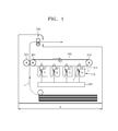
- FIG. 1 illustrates a structure of an image forming apparatus according to an embodiment of the present invention.
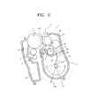
- FIG. 2 illustrates a structure of a developing unit employed in the image forming apparatus of FIG. 1 .
- the image forming apparatus according to the present embodiment is a color image forming apparatus for forming a color image by using four developing units 100 respectively containing toners of cyan C, magenta M, yellow Y, and black K colors.
- the color image forming apparatus of FIG. 1 is referred to as a tandem-type color image forming apparatus.
- members used to form an image of cyan C, magenta M, yellow Y, and black K colors are respectively indicated with suffixes of C, M, Y, and K at the end of each reference numeral.
- the image forming apparatus includes an intermediate transfer belt 300, an exposing unit 200, the four developing units 100, four intermediate transfer rollers 310, a final transfer roller 320, and a fusing unit 500.
- the intermediate transfer belt 300 is an intermediate transfer medium to which a toner image is temporarily transferred before its final transfer to a recording medium P, and runs endlessly by being supported by support rollers 301 and 302.
- Each of the four developing units 100 includes a charge roller 2, a photosensitive drum 1, and a developing roller 3.
- the photosensitive drum 1 is an example of the photosensitive body on which an electrostatic latent image is formed.
- the photosensitive drum 1 includes a photosensitive layer having photoconductivity formed on an outer circumference of a circular metal pipe.
- the charge roller 2 is an example of a charger for charging a surface of the photosensitive drum 1 to a uniform electric potential. A corona charging unit may be employed instead of the charge roller 2.
- the exposing unit 200 scans light modulated according to image information onto the photosensitive drum 1 to form an electrostatic latent image.
- a light emitting diode (LED) type expositing unit for selectively emitting LED light according to the image information via a plurality of LEDs arranged in a main scanning direction may be used as the exposing unit 200.
- a laser scanning unit (LSU) for scanning light emitted by a laser diode onto the photosensitive drum 1 by deflecting the light in the main scanning direction by using a light deflector may be used as the exposing unit 200.
- the developing roller 3 allows the toner contained in each of the four developing units 100 to adhere to the electrostatic latent image formed on the photosensitive drum 1, thereby forming a toner image.
- the four developing units 100 are arranged such that the photosensitive drum 1 faces a lower surface 303 of the intermediate transfer belt 300.
- the photosensitive drum 1 may contact the lower surface 303 of the intermediate transfer belt 300.
- the four intermediate transfer rollers 310 are an example of an intermediate transfer unit for transferring the toner image formed on the photosensitive drum 1 to the intermediate transfer belt 300.
- the four intermediate transfer rollers 310 are respectively located facing the four photosensitive drums 1, with the lower surface 303 of the intermediate transfer belt 300 interposed therebetween.
- An intermediate transfer bias voltage to transfer the toner image formed on the photosensitive drum 1 to the intermediate transfer belt 300 may be applied to the four intermediate transfer rollers 310.
- a corona transfer unit may be employed instead of each of the four intermediate transfer rollers 310.
- the final transfer roller 320 is an example of a final transfer unit for transferring the toner image on the intermediate transfer belt 300 to the recording medium P.
- a final transfer bias voltage to transfer the toner image on the intermediate transfer belt 300 to the recording medium P may be applied to the final transfer roller 320.
- a corona transfer unit may be employed instead of the final transfer roller 320.
- the fusing unit 500 fuses the toner image transferred to the recording medium P by applying heat and pressure to the toner image.
- the exposing unit 200 scans light onto the photosensitive drum 1K charged to a uniform electric potential by the charge roller 2K, thereby forming an electrostatic latent image.
- a development bias is applied to the developing roller 3K of the developing unit 100K, black toner contained in the developing unit 100K adheres to the electrostatic latent image.
- a black toner image developed on the photosensitive drum 1 K is transferred to the intermediate transfer belt 300 by an intermediate bias voltage applied to the intermediate transfer roller 310K.
- Toner images of cyan C, magenta M, and yellow Y colors are transferred to the intermediate transfer belt 300 through the same process and thus a color toner image is formed on the intermediate transfer belt 300.
- the color toner image is transferred to the recording medium P by a final transfer bias voltage applied to the final transfer roller 320.
- the color toner image is fused on the recording medium P by the fusing unit 500.
- Heat generated by the fusing unit 500 may affect the photosensitive drum 1, the toner contained in the four developing units 100, and the exposing unit 200. Since the intermediate transfer belt 300 is interposed between the fusing unit 500, the four developing units 100, and the exposing unit 200 in the image forming apparatus configured as above, the four developing units 100, the photosensitive drum 1, and the exposing unit 200 may be less affected by the heat of the fusing unit 500.
- an internal volume of each of the four developing units 100 is increased.
- the volume of each of the four developing units 100 is increased in a widthwise direction, the width W of the image forming apparatus is increased so that the footprint of the image forming apparatus is increased.
- the four developing units 100 may be increased in a vertical direction, that is, downwardly. In this case, the toner in each of the four developing units 100 may be conveyed in the opposite direction to gravity to be supplied to the developing roller 3.
- FIG. 2 illustrates a detailed structure of one of the four developing units 100 of FIG. 1 .
- a cleaning roller 7 is an example of a charge roller cleaning member for removing foreign materials adhered to an outer circumference of the charge roller 2.
- a cleaning member 6 removes residual toner and foreign materials from a surface of the photosensitive drum 1 before charging.
- the cleaning member 6 may be, for example, a cleaning blade having a leading end contacting the surface of the photosensitive drum 1.
- the residual toner and foreign materials removed from the photosensitive drum 1 may be stored in a waste toner containing unit 10.
- the developing roller 3 is located facing the photosensitive drum 1. When a contact type development method is employed, the developing roller 3 may rotate in contact with the photosensitive drum 1. When a non-contact type development method is employed, the developing roller 3 is separated from the photosensitive drum 1. The interval between the developing roller 3 and the photosensitive drum 1 may be set to be about several tens to several hundreds of microns.
- a supply roller 4 supplies toner toward an outer circumferential surface of the developing roller 3.
- a restriction member 5 restricts the amount of toner supplied to a development region DR between the photosensitive drum 1 and the developing roller 3 facing each other.
- the restriction member 5 may be a restriction blade that elastically contacts the outer circumferential surface of the developing roller 3.
- the developing unit 100 of the present embodiment includes a development portion 30 and a toner storage portion 20.
- the development portion 30 is located above the toner storage portion 20.
- the toner is contained in the toner storage portion 20.
- a toner supply member 9 for supplying the contained toner to the development portion 30 is installed.
- the development portion 30 and the toner storage portion 20 are divided in a vertical direction by a partition wall 40.
- the developing roller 3 and the supply roller 4 are installed in the development portion 30.
- the supply roller 4 rotates in contact with the developing roller 3 or by being separately from the developing roller 3 with a predetermined interval.
- the supply roller 4 supplies the toner contained in the development portion 30 to the developing roller 3.
- An opening portion 50 for forming a path through which the toner may be supplied from the toner storage portion 20 to the development portion 30 is provided in the partition wall 40.
- a right outer wall 31 of the development portion 30 needs to extend to the right in FIG. 2 .
- the width of the developing unit 100 increases so that the overall footprint of the image forming apparatus may be increased.
- the opening portion 50 is located under the lowest portion of the supply roller 4. Also, at least a part of the opening portion 50 is overlapped with a vertical projection area of the supply roller 4.
- the toner supply member 9 may include a rotation shaft 91 and a wing portion 94 formed on the rotation shaft 91 and having elasticity.
- the wing portion 94 elastically contacts a wall portion forming the toner storage portion 20 and conveys toner to the development portion 30 through the opening portion 50.
- the wing portion 94 is formed with a rotation radius 9R that is larger than the longest one of distances from the rotation shaft 91 to an inner wall of the toner storage portion 20 and the partition wall 40. Accordingly, since an end portion of the wing portion 94 enters in the development portion 30 through the opening portion 50, the toner may be effectively conveyed to the development portion 30.
- the wing portion 94 may include a body 92 and a first bent portion 93 bent at an acute angle "A" from the body 92 in a rotation direction of the wing portion 94. Since the body 92 and the first bent portion 93 form a concave space, the toner may be more effectively conveyed to the development portion 30. Also, referring to FIG. 4 , a second bent portion 95 extending from the body 92 in the rotation direction may be further included in the wing portion 94. The second bent portion 95 may extend from the first bent portion 93. Since the second bent portion 95 with the first bent portion 93 forms a concave space to convey the toner, the toner may be conveyed more effectively to the development portion 30. According to the above-described structure, as the toner supply member 9 rotates, the wing portion 94 may convey the toner by elastically contacting the wall forming the toner storage portion 20 and supply the toner to the development portion 30 through the opening portion 50.
- the toner supplied to the development portion 30 may be supplied by the supply roller 4 to the developing roller 3 and may adhere to the surface of the developing roller 3.
- the supply roller 4 may rotate in the same direction as the rotation direction of the developing roller 3. That is, the surface of the supply roller 4 and the surface of the developing roller 3 are moved in the opposite directions in a region E where the supply roller 4 and the developing roller 3 face each other. Accordingly, the toner remaining on the surface of the developing roller 3 after passing through the development region DR is removed by the supply roller 4 at the upstream side of the region E with respect to the rotation direction of the developing roller 3, and new toner may adhere to the surface of the developing roller 3 in the region E.
- an auxiliary supply member 8 may be installed in the development portion 30.
- the auxiliary supply member 8 is located between the partition wall 40 and the supply roller 4 to supply toner to the region E.
- the auxiliary supply member 8 is located at a more downstream side than the supply roller 4 with respect to the rotation direction of the developing roller 3.
- a rotation center 83 of the auxiliary supply member 8 is located between a vertical straight line L2 passing through the center of the developing roller 3 and a vertical straight line L1 passing through the center of the supply roller 4.
- the opening portion 50 is not overlapped with a vertical projection of the auxiliary supply member 8. Otherwise, toner would fall from the development portion 30 to the toner storage portion 20 through the opening portion 50 and toner supply performance of the auxiliary supply member 8 would deteriorate.
- Toner is supplied from the toner storage portion 20 to the development portion 30 according to a rotation cycle of the toner supply member 9.
- a toner pressure is applied to the region E.
- the toner pressure in the region E may decrease so that a sufficient amount of toner may not adhere to the developing roller 3.
- the auxiliary supply member 8 also applies a toner pressure to the region E, a sufficient amount of toner may be supplied to the developing roller 3.
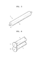
- the auxiliary supply member 8 may have, for example, a roller shape formed of a metal material or a plastic material, as illustrated in FIG. 5 .
- the roller portion 82 may be formed of a plastic, metal, or rubber material.
- the roller portion 82 may have a porous structure such as sponge. Also, a surface of the roller portion 82 may have a surface roughness.
- the auxiliary supply member 8 rotates in the opposite direction to the rotation direction of the supply roller 4. That is, in a region where the auxiliary supply member 8 faces the supply roller 4, the direction in which the surface of the auxiliary supply member 8 moves is the same as the direction in which the surface of the supply roller 4 moves. According to the above-described structure, the rotational forces of the supply roller 4 and the auxiliary supply roller 8 may effectively work as a toner conveying force in passing through the region where the auxiliary supply member 8 and the supply roller 4 face each other.
- first and second gears 4G and 8G are respectively coupled to the rotation shafts of the supply roller 4 and the auxiliary supply member 8 so that the first and second gears 4G and 8G are directly engaged with each other.
- the rotation force fails to work effectively as a toner conveying force in the region, and an odd number of idle gears are required to be installed between the first and second gears 4G and 8G.
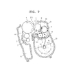
- the toner supplied by the toner supply member 9 from the toner storage portion 20 to the development portion 30 is conveyed to the region E and applies a toner pressure to the region E. Excess toner is removed from the region E through a gap between the auxiliary supply member 8 and the partition wall 40. Also, the toner removed from the developing roller 3 by the supply roller 4 at the upstream of the region E is discharged through a gap between the supply roller 4 and the right outer wall 31. The removed toner falls down to the toner storage portion 20 through the opening portion 50. Thus, an appropriate toner pressure is maintained in the region E. The toner removed from the region E is mixed with the toner in the toner storage portion 20 and supplied back to the development portion 30.
- the toner may be effectively supplied to the developing roller 3 in the opposite direction to gravity.
- the developing unit 100 may be enlarged in the gravity direction and the toner capacity of the developing unit 100 may be increased without increasing the dimension of the developing unit 100 in a widthwise direction. In other words, the footprint of the image forming apparatus may be reduced. Also, since the toner may be uniformly and stably supplied to the developing roller 3, uniformity in the quality of an image may be obtained.
- the auxiliary supply member 8 and the supply roller 4 may rotate in contact with each other or may be separated from each other.
- the toner conveyed from the toner storage portion 20 to the development portion 30 is supplied to the region E by passing through the region where the auxiliary supply member 8 and the supply roller 4 face each other by the rotational forces of the auxiliary supply member 8 and the supply roller 4. That is, the rotational forces of the auxiliary supply member 8 and the supply roller 4 provide kinetic energy to the toner that is powder so that the toner is supplied to the region E by the kinetic energy.
- the distance between the auxiliary supply member 8 and the supply roller 4 needs to be regulated.
- the distance between the surfaces of the auxiliary supply member 8 and the supply roller 4 in the region where the auxiliary supply member 8 and the supply roller 4 face each other is between -1 mm and +1 mm, superior toner supply characteristic may be obtained.
- the distance between the surfaces of the auxiliary supply member 8 and the supply roller 4 is a positive (+) value, it means that the surfaces of the auxiliary supply member 8 and the supply roller 4 are separated from each other.
- the distance between the surfaces of the auxiliary supply member 8 and the supply roller 4 is a negative (-) value, it means that the surfaces of the auxiliary supply member 8 and the supply roller 4 are in contact with each other or by being overlapped with each other.
- the rotational forces of the auxiliary supply member 8 and the supply roller 4 do not effectively work as a toner conveying force. Then, the amount of the toner supplied to the developing roller 3 becomes insufficient so that the concentration of a printed image is deteriorated or becomes irregular. Also, when the amount of overlapping between the surfaces of the auxiliary supply member 8 and the supply roller 4 is greater than 1.0 mm, rotation load of the auxiliary supply member 8 and the supply roller 4 may become severe so that a toner conveying characteristic may be deteriorated.
- at least one of the auxiliary supply member 8 and the supply roller 4 may have a surface formed of an elastic material such as rubber, foamed rubber, or sponge.
- Table 1 shows a result of the relative quality of a printed image by varying the distance between the surfaces of the auxiliary supply member 8 and the supply roller 4. The results show that, when the Inequality 1 is satisfied, a sufficient amount of toner is uniformly supplied to the developing roller 3 so that an image of a uniform and superior quality may be obtained.
- Table 1 > Experiment Experiment Experiment Experiment 1 2 3 4 Distance between surfaces of the auxiliary supply member and the supply roller (mm) Image quality 1.1 0.8 0.6 0.25 Defective Not bad Excellent Excellent Excellent
- the toner supply characteristic may be affected by the rotation speeds of the auxiliary supply member 8 and the supply roller 4.
- the ratio of the rotation speed between the auxiliary supply member 8 and the supply roller 4 is about 50-90%, a superior toner supply characteristic may be obtained.
- the toner supplied to the development portion 30 through the opening portion 50 may strongly tend to escape from the region E through a gap between the partition wall 40 and the auxiliary supply roller 8 after passing through the region E other so that a toner supply characteristic toward the region E may be deteriorated.
- the rotation linear velocity of the auxiliary supply roller 8 is too slow, a force to convey the toner supplied to the development portion 30 through the opening portion 50 toward the region E after passing through the region E is weakened so that a toner supply characteristic toward the region E may be deteriorated.
- Table 2 shows a result of the relative quality of an image by varying a rate of the rotation linear velocity of the auxiliary supply roller 8 with respect to the rotation linear velocity of the supply roller 4. The results show that, when the rotation linear velocity rate of the auxiliary supply roller 8 and the supply roller 4 is about 50-90%, a sufficient amount of toner is supplied to the developing roller 3 so that a uniform and superior quality of an image may be obtained.
- Table 2 > Experiment Experiment Experiment Experiment Experiment Experiment Experiment Experiment 1 2 3 4 5 Rotation linear velocity Rate between the between auxiliary supply member and the supply roller Image quality 140% 100% 85% 50% 0% Defective Not bad Excellent Excellent Excellent Defective
- the rotation linear velocity rate of the auxiliary supply roller 8 and the supply roller 4 may be adjusted by varying the number of teeth of the first and second gears 4G and 8G. That is, the number of teeth of the second gear 8G may be greater than that of the first gear 4G considering the rotation linear velocity rate of the auxiliary supply roller 8 and the supply roller 4. In this case, a module of the first and second gears 4G and 8G may be adjusted considering the distance between the centers of the auxiliary supply roller 8 and the supply roller 4.
- the toner storage portion 20 is arranged under the development portion 30, the present invention is not limited thereto.
- the toner storage portion 20 may be arranged at the side of the development portion 30.
- One or more toner supply members 21 for supplying toner to the development portion 30 may be provided in the toner storage portion 20.
- the toner supply members 21 may be augers having spiral wings or elastic wing portion coupled to a rotational shaft.
- the auxiliary supply roller 8 is located between the supply roller 4 and a lower wall 41 of the developing unit 100 and supplies toner to the region E where the supply roller 4 and the developing roller 3 face each other.
- the auxiliary supply roller 8 is located at a more downstream side than the supply roller 4 with respect to the rotation direction of the developing roller 3.
- a rotation center 83 of the auxiliary supply member 8 is located between a vertical straight line L2 passing through the center of the developing roller 3 and a vertical straight line L1 passing through the center of the supply roller 4.
- auxiliary supply roller 8 applies a toner pressure to the region E, a sufficient amount of toner may be supplied to the developing roller 3 without relying on the rotation cycle of the toner supply member 21. Since the movement direction of the surface of the auxiliary supply roller 8 is the same as that of the surface of the supply roller 4 in the region E, the rotational forces of the auxiliary supply member 8 and the supply roller 4 may effectively work to convey the toner passing through the region E.
- the toner supplied by the toner supply members 21 from the toner storage portion 20 to the development portion 30 is conveyed to the region E through a gap between the auxiliary supply roller 8 and the supply roller 4 and applies a toner pressure to the region E. Excess toner is removed from the region E through the gap between the auxiliary supply member 8 and the lower wall 41. Also, the toner removed from the developing roller 3 by the supply roller 4 at the upstream of the region E is discharged to the toner storage portion 20 as the supply roller 4 rotates. Thus, an appropriate toner pressure is maintained in the region E. The toner removed from the region E is mixed with the toner in the toner storage portion 20 and supplied back to the development portion 30.
- the auxiliary supply member 8 and the supply roller 4 may rotate in contact with each other or be separated from each other. Assuming that the distance between the centers of the auxiliary supply member 8 and the supply roller 4 in the region E is D, the radius of the supply roller 4 is R1, and the radius of the auxiliary supply member 8 is R2, when the above Inequality 1 is satisfied, a superior toner supply characteristic may be obtained. Also, when the rotation linear velocity rate of the auxiliary supply roller 8 and the supply roller 4 is about 50-90%, a superior toner supply characteristic may be obtained.
- toner may be uniformly and effectively conveyed to the developing roller regardless of the position of the toner storage portion to the development portion. Also, since the toner may be circulated between the toner storage portion and the development portion, the stagnation of toner in the toner storage portion and the development portion may be prevented. Therefore, a uniform image quality may be obtained.
Landscapes
- Physics & Mathematics (AREA)
- General Physics & Mathematics (AREA)
- Dry Development In Electrophotography (AREA)
Abstract
Description
- This application claims the benefit of Korean Patent Application No.
10-2010-0082644, filed on August 25, 2010 - The present invention relates to a developing unit that is detachable from an image forming apparatus, and an image forming apparatus employing the developing unit.
- In electrophotographic image forming apparatuses, an electrostatic latent image is formed on a surface of a photosensitive body by scanning light that is modulated according to image information onto the photosensitive body, the electrostatic latent image is developed into a visible toner image by supplying toner to the electrostatic latent image, and the toner image is transferred to a recording medium and fused thereto so that an image is printed on the recording medium.
- The electrophotographic image forming apparatuses include a developing unit containing a developer. A one-component developing unit contains toner as a developer, whereas a two-component developing unit contains toner and carrier as a developer. When all the developer contained in a developing unit is consumed, the developing unit is detached from an image forming apparatus and a new developing unit is installed in the image forming apparatus.
- According to the present invention there is provided a developing unit and an electrophotographic image forming apparatus including said developing unit as set forth in the appended claims. Other features of the invention will be apparent from the dependent claims, and the description which follows.
- The present invention provides a developing unit that is capable of effectively supplying toner in the developing unit to a developing roller, and an electrophotographic image forming apparatus employing the developing unit.
- According to an aspect of the present invention, a developing unit includes a toner storage portion for containing toner, a development portion for containing the toner supplied from the toner storage portion and in which a developing roller for supplying the toner to a photosensitive body is installed, and a supply roller and an auxiliary supply roller installed at the development portion, the supply roller and the auxiliary supply roller rotating while facing each other to supply the toner to the developing roller, wherein an inequality that |D - (R1 + R2)| ≤ 1.0 mm is satisfied, where a distance between the centers of the auxiliary supply roller and the supply roller in a region where the auxiliary supply roller and the supply roller face each other is D, a radius of the supply roller is R1, and a radius of the auxiliary supply roller is R2.
- The auxiliary supply roller may be located under the supply roller and at a more downstream side than the supply roller with respect to a rotation direction of the developing roller.
- The center of the auxiliary supply roller may be located between a vertical straight line passing through the center of the supply roller and a vertical straight line passing through the center of the developing roller.
- The supply roller and the auxiliary supply roller may rotate such that surfaces of the supply roller and the auxiliary supply roller move in the same direction in the region, and the supply roller and the developing roller may rotate such that surfaces of the supply roller and the developing roller move in the opposite directions in the region.
- The developing unit may include first and second gears which are respectively inserted around rotation shafts of the supply roller and the auxiliary supply roller, the first and second gears being directly engaged with each other. The number of teeth of the second gear may be greater than the number of teeth of the first gear.
- A rotation linear velocity of the auxiliary supply roller may be about 50-90% of a rotation linear velocity of the supply roller.
- The developing unit may further include a restriction member located at a downstream side of the auxiliary supply roller with respect to a rotation direction of the developing roller and restricting the amount of toner adhering to a surface of the developing roller.
- The toner storage portion may be located at a side portion of the development portion.
- The toner storage portion may be located under the development portion. The developing unit may further include a partition wall dividing the toner storage portion and the development portion, having an opening portion located under the lowest portion of the supply roller, and forming a path of the toner that is supplied from the toner storage portion to the development portion; and a toner supply member located in the toner storage portion and supplying the toner to the development portion through the opening portion. The opening porion dies not overlap a vertical projection of the auxiliary supply roller.
- According to another aspect of the present invention, an electrophotographic image forming apparatus includes a photosensitive body, an exposing unit for forming an electrostatic latent image on the photosensitive body, a developing unit mentioned above for developing the electrostatic latent image by supplying toner to the electrostatic latent image, and a fusing unit for fusing a toner image transferred to a recording medium.
- The above and other features and advantages of the present invention will become more apparent by describing in detail exemplary embodiments thereof with reference to the attached drawings in which:
-
FIG. 1 illustrates a structure of an image forming apparatus according to an embodiment of the present invention; -
FIG. 2 illustrates a structure of a developing unit according to an embodiment of the present invention; -
FIG. 3 is a perspective view of a toner supply member according to an embodiment of the present invention; -
FIG. 4 is a perspective view of a toner supply member according to another embodiment of the present invention; -
FIG. 5 is a perspective view of an auxiliary supply roller according to an embodiment of the present invention; -
FIG. 6 is a perspective view illustrating a part of a gear engagement structure for rotating the supply roller and the auxiliary supply roller; -
FIG. 7 illustrates a toner circulation process in the developing unit ofFIG. 2 , according to an embodiment of the present invention; -
FIG. 8 illustrates a distance between the auxiliary supply roller and the supply roller; -
FIG. 9 illustrates an operation of toner when the distance between the auxiliary supply roller and the supply roller is excessively large; and -
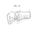
FIG. 10 illustrates a structure of a developing unit according to another embodiment of the present invention. - The attached drawings for illustrating exemplary embodiments of the present invention are referred to in order to gain a sufficient understanding of the present invention, the merits thereof, and the objectives accomplished by the implementation of the present invention. Hereinafter, the present invention will be described in detail by explaining exemplary embodiments of the invention with reference to the attached drawings. Like reference numerals in the drawings denote like elements.
-
FIG. 1 illustrates a structure of an image forming apparatus according to an embodiment of the present invention.FIG. 2 illustrates a structure of a developing unit employed in the image forming apparatus ofFIG. 1 . The image forming apparatus according to the present embodiment is a color image forming apparatus for forming a color image by using four developingunits 100 respectively containing toners of cyan C, magenta M, yellow Y, and black K colors. The color image forming apparatus ofFIG. 1 is referred to as a tandem-type color image forming apparatus. In the following descriptions, members used to form an image of cyan C, magenta M, yellow Y, and black K colors are respectively indicated with suffixes of C, M, Y, and K at the end of each reference numeral. - Referring to
FIG. 1 , the image forming apparatus according to the present embodiment includes anintermediate transfer belt 300, anexposing unit 200, the four developingunits 100, fourintermediate transfer rollers 310, afinal transfer roller 320, and afusing unit 500. - The
intermediate transfer belt 300 is an intermediate transfer medium to which a toner image is temporarily transferred before its final transfer to a recording medium P, and runs endlessly by being supported bysupport rollers units 100 includes acharge roller 2, aphotosensitive drum 1, and a developingroller 3. Thephotosensitive drum 1 is an example of the photosensitive body on which an electrostatic latent image is formed. Thephotosensitive drum 1 includes a photosensitive layer having photoconductivity formed on an outer circumference of a circular metal pipe. Thecharge roller 2 is an example of a charger for charging a surface of thephotosensitive drum 1 to a uniform electric potential. A corona charging unit may be employed instead of thecharge roller 2. The exposingunit 200 scans light modulated according to image information onto thephotosensitive drum 1 to form an electrostatic latent image. A light emitting diode (LED) type expositing unit for selectively emitting LED light according to the image information via a plurality of LEDs arranged in a main scanning direction may be used as the exposingunit 200. Also, a laser scanning unit (LSU) for scanning light emitted by a laser diode onto thephotosensitive drum 1 by deflecting the light in the main scanning direction by using a light deflector may be used as theexposing unit 200. The developingroller 3 allows the toner contained in each of the four developingunits 100 to adhere to the electrostatic latent image formed on thephotosensitive drum 1, thereby forming a toner image. - The four developing
units 100 are arranged such that thephotosensitive drum 1 faces alower surface 303 of theintermediate transfer belt 300. Thephotosensitive drum 1 may contact thelower surface 303 of theintermediate transfer belt 300. The fourintermediate transfer rollers 310 are an example of an intermediate transfer unit for transferring the toner image formed on thephotosensitive drum 1 to theintermediate transfer belt 300. The fourintermediate transfer rollers 310 are respectively located facing the fourphotosensitive drums 1, with thelower surface 303 of theintermediate transfer belt 300 interposed therebetween. An intermediate transfer bias voltage to transfer the toner image formed on thephotosensitive drum 1 to theintermediate transfer belt 300 may be applied to the fourintermediate transfer rollers 310. A corona transfer unit may be employed instead of each of the fourintermediate transfer rollers 310. - The
final transfer roller 320 is an example of a final transfer unit for transferring the toner image on theintermediate transfer belt 300 to the recording medium P. A final transfer bias voltage to transfer the toner image on theintermediate transfer belt 300 to the recording medium P may be applied to thefinal transfer roller 320. A corona transfer unit may be employed instead of thefinal transfer roller 320. Thefusing unit 500 fuses the toner image transferred to the recording medium P by applying heat and pressure to the toner image. - A color image forming process according to the above-described structure will be briefly described below.
- First, according to image information of a black K color, the exposing
unit 200 scans light onto the photosensitive drum 1K charged to a uniform electric potential by the charge roller 2K, thereby forming an electrostatic latent image. When a development bias is applied to the developing roller 3K of the developing unit 100K, black toner contained in the developing unit 100K adheres to the electrostatic latent image. A black toner image developed on the photosensitive drum 1 K is transferred to theintermediate transfer belt 300 by an intermediate bias voltage applied to the intermediate transfer roller 310K. Toner images of cyan C, magenta M, and yellow Y colors are transferred to theintermediate transfer belt 300 through the same process and thus a color toner image is formed on theintermediate transfer belt 300. The color toner image is transferred to the recording medium P by a final transfer bias voltage applied to thefinal transfer roller 320. The color toner image is fused on the recording medium P by thefusing unit 500. - Heat generated by the
fusing unit 500 may affect thephotosensitive drum 1, the toner contained in the four developingunits 100, and the exposingunit 200. Since theintermediate transfer belt 300 is interposed between the fusingunit 500, the four developingunits 100, and the exposingunit 200 in the image forming apparatus configured as above, the four developingunits 100, thephotosensitive drum 1, and the exposingunit 200 may be less affected by the heat of thefusing unit 500. - In order to increase the toner capacity of the four developing
units 100, an internal volume of each of the four developingunits 100 is increased. When the volume of each of the four developingunits 100 is increased in a widthwise direction, the width W of the image forming apparatus is increased so that the footprint of the image forming apparatus is increased. Thus, to increase the toner capacity of the four developingunits 100 without increasing the footprint of the image forming apparatus, the four developingunits 100 may be increased in a vertical direction, that is, downwardly. In this case, the toner in each of the four developingunits 100 may be conveyed in the opposite direction to gravity to be supplied to the developingroller 3. -
FIG. 2 illustrates a detailed structure of one of the four developingunits 100 ofFIG. 1 . Referring toFIG. 2 , a cleaningroller 7 is an example of a charge roller cleaning member for removing foreign materials adhered to an outer circumference of thecharge roller 2. A cleaningmember 6 removes residual toner and foreign materials from a surface of thephotosensitive drum 1 before charging. The cleaningmember 6 may be, for example, a cleaning blade having a leading end contacting the surface of thephotosensitive drum 1. The residual toner and foreign materials removed from thephotosensitive drum 1 may be stored in a wastetoner containing unit 10. - The developing
roller 3 is located facing thephotosensitive drum 1. When a contact type development method is employed, the developingroller 3 may rotate in contact with thephotosensitive drum 1. When a non-contact type development method is employed, the developingroller 3 is separated from thephotosensitive drum 1. The interval between the developingroller 3 and thephotosensitive drum 1 may be set to be about several tens to several hundreds of microns. Asupply roller 4 supplies toner toward an outer circumferential surface of the developingroller 3. - A
restriction member 5 restricts the amount of toner supplied to a development region DR between thephotosensitive drum 1 and the developingroller 3 facing each other. For example, therestriction member 5 may be a restriction blade that elastically contacts the outer circumferential surface of the developingroller 3. - The developing
unit 100 of the present embodiment includes adevelopment portion 30 and atoner storage portion 20. Thedevelopment portion 30 is located above thetoner storage portion 20. The toner is contained in thetoner storage portion 20. Atoner supply member 9 for supplying the contained toner to thedevelopment portion 30 is installed. Thedevelopment portion 30 and thetoner storage portion 20 are divided in a vertical direction by apartition wall 40. - The developing
roller 3 and thesupply roller 4 are installed in thedevelopment portion 30. Thesupply roller 4 rotates in contact with the developingroller 3 or by being separately from the developingroller 3 with a predetermined interval. Thesupply roller 4 supplies the toner contained in thedevelopment portion 30 to the developingroller 3. - An opening
portion 50 for forming a path through which the toner may be supplied from thetoner storage portion 20 to thedevelopment portion 30 is provided in thepartition wall 40. In order for the openingportion 50 to be located above the lowest portion of thesupply roller 4, a rightouter wall 31 of thedevelopment portion 30 needs to extend to the right inFIG. 2 . Then, the width of the developingunit 100 increases so that the overall footprint of the image forming apparatus may be increased. However, to minimize an increase in the footprint of the image forming apparatus, the openingportion 50 is located under the lowest portion of thesupply roller 4. Also, at least a part of the openingportion 50 is overlapped with a vertical projection area of thesupply roller 4. - The
toner supply member 9 may include arotation shaft 91 and awing portion 94 formed on therotation shaft 91 and having elasticity. When thetoner supply member 9 rotates, thewing portion 94 elastically contacts a wall portion forming thetoner storage portion 20 and conveys toner to thedevelopment portion 30 through the openingportion 50. To increase a rate of use of the toner in thetoner storage portion 20, thewing portion 94 is formed with arotation radius 9R that is larger than the longest one of distances from therotation shaft 91 to an inner wall of thetoner storage portion 20 and thepartition wall 40. Accordingly, since an end portion of thewing portion 94 enters in thedevelopment portion 30 through the openingportion 50, the toner may be effectively conveyed to thedevelopment portion 30. Referring toFIG. 3 , thewing portion 94 may include abody 92 and a firstbent portion 93 bent at an acute angle "A" from thebody 92 in a rotation direction of thewing portion 94. Since thebody 92 and the firstbent portion 93 form a concave space, the toner may be more effectively conveyed to thedevelopment portion 30. Also, referring toFIG. 4 , a secondbent portion 95 extending from thebody 92 in the rotation direction may be further included in thewing portion 94. The secondbent portion 95 may extend from the firstbent portion 93. Since the secondbent portion 95 with the firstbent portion 93 forms a concave space to convey the toner, the toner may be conveyed more effectively to thedevelopment portion 30. According to the above-described structure, as thetoner supply member 9 rotates, thewing portion 94 may convey the toner by elastically contacting the wall forming thetoner storage portion 20 and supply the toner to thedevelopment portion 30 through the openingportion 50. - In the above-described structure, the toner supplied to the
development portion 30 may be supplied by thesupply roller 4 to the developingroller 3 and may adhere to the surface of the developingroller 3. Thesupply roller 4 may rotate in the same direction as the rotation direction of the developingroller 3. That is, the surface of thesupply roller 4 and the surface of the developingroller 3 are moved in the opposite directions in a region E where thesupply roller 4 and the developingroller 3 face each other. Accordingly, the toner remaining on the surface of the developingroller 3 after passing through the development region DR is removed by thesupply roller 4 at the upstream side of the region E with respect to the rotation direction of the developingroller 3, and new toner may adhere to the surface of the developingroller 3 in the region E. - Referring to
FIG. 2 , anauxiliary supply member 8 may be installed in thedevelopment portion 30. Theauxiliary supply member 8 is located between thepartition wall 40 and thesupply roller 4 to supply toner to the region E. Theauxiliary supply member 8 is located at a more downstream side than thesupply roller 4 with respect to the rotation direction of the developingroller 3. Arotation center 83 of theauxiliary supply member 8 is located between a vertical straight line L2 passing through the center of the developingroller 3 and a vertical straight line L1 passing through the center of thesupply roller 4. The openingportion 50 is not overlapped with a vertical projection of theauxiliary supply member 8. Otherwise, toner would fall from thedevelopment portion 30 to thetoner storage portion 20 through the openingportion 50 and toner supply performance of theauxiliary supply member 8 would deteriorate. - Toner is supplied from the
toner storage portion 20 to thedevelopment portion 30 according to a rotation cycle of thetoner supply member 9. When thewing portion 94 of thetoner supply member 9 pushes the toner into thedevelopment portion 30 through the openingportion 50, a toner pressure is applied to the region E. When thewing portion 94 is out of the openingportion 50, the toner pressure in the region E may decrease so that a sufficient amount of toner may not adhere to the developingroller 3. As theauxiliary supply member 8 also applies a toner pressure to the region E, a sufficient amount of toner may be supplied to the developingroller 3. - The
auxiliary supply member 8 may have, for example, a roller shape formed of a metal material or a plastic material, as illustrated inFIG. 5 . When theauxiliary supply member 8 includes arotation shaft 81 and aroller portion 82, theroller portion 82 may be formed of a plastic, metal, or rubber material. Theroller portion 82 may have a porous structure such as sponge. Also, a surface of theroller portion 82 may have a surface roughness. - The
auxiliary supply member 8 rotates in the opposite direction to the rotation direction of thesupply roller 4. That is, in a region where theauxiliary supply member 8 faces thesupply roller 4, the direction in which the surface of theauxiliary supply member 8 moves is the same as the direction in which the surface of thesupply roller 4 moves. According to the above-described structure, the rotational forces of thesupply roller 4 and theauxiliary supply roller 8 may effectively work as a toner conveying force in passing through the region where theauxiliary supply member 8 and thesupply roller 4 face each other. - In order for the
auxiliary supply member 8 to rotate in the opposite direction to the rotation direction of thesupply roller 4, as illustrated inFIG. 6 , first andsecond gears supply roller 4 and theauxiliary supply member 8 so that the first andsecond gears auxiliary supply member 8 rotates in the same direction as thesupply roller 4, the rotation force fails to work effectively as a toner conveying force in the region, and an odd number of idle gears are required to be installed between the first andsecond gears - Referring to
FIG. 7 , the toner supplied by thetoner supply member 9 from thetoner storage portion 20 to thedevelopment portion 30 is conveyed to the region E and applies a toner pressure to the region E. Excess toner is removed from the region E through a gap between theauxiliary supply member 8 and thepartition wall 40. Also, the toner removed from the developingroller 3 by thesupply roller 4 at the upstream of the region E is discharged through a gap between thesupply roller 4 and the rightouter wall 31. The removed toner falls down to thetoner storage portion 20 through the openingportion 50. Thus, an appropriate toner pressure is maintained in the region E. The toner removed from the region E is mixed with the toner in thetoner storage portion 20 and supplied back to thedevelopment portion 30. As the toner circulates as described above, the toner may be effectively supplied to the developingroller 3 in the opposite direction to gravity. Thus, the developingunit 100 may be enlarged in the gravity direction and the toner capacity of the developingunit 100 may be increased without increasing the dimension of the developingunit 100 in a widthwise direction. In other words, the footprint of the image forming apparatus may be reduced. Also, since the toner may be uniformly and stably supplied to the developingroller 3, uniformity in the quality of an image may be obtained. - The
auxiliary supply member 8 and thesupply roller 4 may rotate in contact with each other or may be separated from each other. The toner conveyed from thetoner storage portion 20 to thedevelopment portion 30 is supplied to the region E by passing through the region where theauxiliary supply member 8 and thesupply roller 4 face each other by the rotational forces of theauxiliary supply member 8 and thesupply roller 4. That is, the rotational forces of theauxiliary supply member 8 and thesupply roller 4 provide kinetic energy to the toner that is powder so that the toner is supplied to the region E by the kinetic energy. In order to stably and uniformly convey the toner to the region E while theauxiliary supply member 8 and thesupply roller 4 rotate facing each other, the distance between theauxiliary supply member 8 and thesupply roller 4 needs to be regulated. When the distance between theauxiliary supply member 8 and thesupply roller 4 is too large, the rotational forces of theauxiliary supply member 8 and thesupply roller 4 do not effectively work as a toner conveying force so that the fluidity and supply of the toner may be deteriorated. Also, when the amount of contact between theauxiliary supply member 8 and thesupply roller 4 is too large, rotation load may be excessively increased. - Referring to
FIG. 8 , assuming that the distance between the centers of theauxiliary supply member 8 and thesupply roller 4 in the region where theauxiliary supply member 8 and thesupply roller 4 face each other is D, the radius of thesupply roller 4 is R1, and the radius of theauxiliary supply member 8 is R2, when the followinginequality 1 is satisfied, a superior toner supply characteristic may be obtained. -

- That is, when the distance between the surfaces of the
auxiliary supply member 8 and thesupply roller 4 in the region where theauxiliary supply member 8 and thesupply roller 4 face each other is between -1 mm and +1 mm, superior toner supply characteristic may be obtained. When the distance between the surfaces of theauxiliary supply member 8 and thesupply roller 4 is a positive (+) value, it means that the surfaces of theauxiliary supply member 8 and thesupply roller 4 are separated from each other. When the distance between the surfaces of theauxiliary supply member 8 and thesupply roller 4 is a negative (-) value, it means that the surfaces of theauxiliary supply member 8 and thesupply roller 4 are in contact with each other or by being overlapped with each other. When the distance between the surfaces of theauxiliary supply member 8 and thesupply roller 4 is greater than 1.0 mm, the rotational forces of theauxiliary supply member 8 and thesupply roller 4 do not effectively work as a toner conveying force. Then, the amount of the toner supplied to the developingroller 3 becomes insufficient so that the concentration of a printed image is deteriorated or becomes irregular. Also, when the amount of overlapping between the surfaces of theauxiliary supply member 8 and thesupply roller 4 is greater than 1.0 mm, rotation load of theauxiliary supply member 8 and thesupply roller 4 may become severe so that a toner conveying characteristic may be deteriorated. When theauxiliary supply member 8 and thesupply roller 4 rotated in contact with each other or overlap each other, at least one of theauxiliary supply member 8 and thesupply roller 4 may have a surface formed of an elastic material such as rubber, foamed rubber, or sponge. - Table 1 shows a result of the relative quality of a printed image by varying the distance between the surfaces of the
auxiliary supply member 8 and thesupply roller 4. The results show that, when theInequality 1 is satisfied, a sufficient amount of toner is uniformly supplied to the developingroller 3 so that an image of a uniform and superior quality may be obtained.<Table 1 > Experiment Experiment Experiment Experiment 1 2 3 4 Distance between surfaces of the auxiliary supply member and the supply roller (mm) Image quality 1.1 0.8 0.6 0.25 Defective Not bad Excellent Excellent - The toner supply characteristic may be affected by the rotation speeds of the
auxiliary supply member 8 and thesupply roller 4. When the ratio of the rotation speed between theauxiliary supply member 8 and thesupply roller 4 is about 50-90%, a superior toner supply characteristic may be obtained. - When the rotation linear velocity of the
auxiliary supply roller 8 is too fast, as illustrated inFIG. 9 , the toner supplied to thedevelopment portion 30 through the openingportion 50 may strongly tend to escape from the region E through a gap between thepartition wall 40 and theauxiliary supply roller 8 after passing through the region E other so that a toner supply characteristic toward the region E may be deteriorated. When the rotation linear velocity of theauxiliary supply roller 8 is too slow, a force to convey the toner supplied to thedevelopment portion 30 through the openingportion 50 toward the region E after passing through the region E is weakened so that a toner supply characteristic toward the region E may be deteriorated. - Table 2 shows a result of the relative quality of an image by varying a rate of the rotation linear velocity of the
auxiliary supply roller 8 with respect to the rotation linear velocity of thesupply roller 4. The results show that, when the rotation linear velocity rate of theauxiliary supply roller 8 and thesupply roller 4 is about 50-90%, a sufficient amount of toner is supplied to the developingroller 3 so that a uniform and superior quality of an image may be obtained.<Table 2> Experiment Experiment Experiment Experiment Experiment 1 2 3 4 5 Rotation linear velocity Rate between the between auxiliary supply member and the supply roller Image quality 140% 100% 85% 50% 0% Defective Not bad Excellent Excellent Defective - The rotation linear velocity rate of the
auxiliary supply roller 8 and thesupply roller 4 may be adjusted by varying the number of teeth of the first andsecond gears second gear 8G may be greater than that of thefirst gear 4G considering the rotation linear velocity rate of theauxiliary supply roller 8 and thesupply roller 4. In this case, a module of the first andsecond gears auxiliary supply roller 8 and thesupply roller 4. - Although in the above-described embodiment the
toner storage portion 20 is arranged under thedevelopment portion 30, the present invention is not limited thereto. For example, as illustrated inFIG. 10 , thetoner storage portion 20 may be arranged at the side of thedevelopment portion 30. One or moretoner supply members 21 for supplying toner to thedevelopment portion 30 may be provided in thetoner storage portion 20. Thetoner supply members 21 may be augers having spiral wings or elastic wing portion coupled to a rotational shaft. - The
auxiliary supply roller 8 is located between thesupply roller 4 and alower wall 41 of the developingunit 100 and supplies toner to the region E where thesupply roller 4 and the developingroller 3 face each other. Theauxiliary supply roller 8 is located at a more downstream side than thesupply roller 4 with respect to the rotation direction of the developingroller 3. Arotation center 83 of theauxiliary supply member 8 is located between a vertical straight line L2 passing through the center of the developingroller 3 and a vertical straight line L1 passing through the center of thesupply roller 4. - Since the
auxiliary supply roller 8 applies a toner pressure to the region E, a sufficient amount of toner may be supplied to the developingroller 3 without relying on the rotation cycle of thetoner supply member 21. Since the movement direction of the surface of theauxiliary supply roller 8 is the same as that of the surface of thesupply roller 4 in the region E, the rotational forces of theauxiliary supply member 8 and thesupply roller 4 may effectively work to convey the toner passing through the region E. - The toner supplied by the
toner supply members 21 from thetoner storage portion 20 to thedevelopment portion 30 is conveyed to the region E through a gap between theauxiliary supply roller 8 and thesupply roller 4 and applies a toner pressure to the region E. Excess toner is removed from the region E through the gap between theauxiliary supply member 8 and thelower wall 41. Also, the toner removed from the developingroller 3 by thesupply roller 4 at the upstream of the region E is discharged to thetoner storage portion 20 as thesupply roller 4 rotates. Thus, an appropriate toner pressure is maintained in the region E. The toner removed from the region E is mixed with the toner in thetoner storage portion 20 and supplied back to thedevelopment portion 30. - The
auxiliary supply member 8 and thesupply roller 4 may rotate in contact with each other or be separated from each other. Assuming that the distance between the centers of theauxiliary supply member 8 and thesupply roller 4 in the region E is D, the radius of thesupply roller 4 is R1, and the radius of theauxiliary supply member 8 is R2, when theabove Inequality 1 is satisfied, a superior toner supply characteristic may be obtained. Also, when the rotation linear velocity rate of theauxiliary supply roller 8 and thesupply roller 4 is about 50-90%, a superior toner supply characteristic may be obtained. - According to the above-described developing unit according to the present invention and the image forming apparatus adopting the same, toner may be uniformly and effectively conveyed to the developing roller regardless of the position of the toner storage portion to the development portion. Also, since the toner may be circulated between the toner storage portion and the development portion, the stagnation of toner in the toner storage portion and the development portion may be prevented. Therefore, a uniform image quality may be obtained.
- While this invention has been particularly shown and described with reference to exemplary embodiments thereof, it will be understood by those skilled in the art that various changes in form and details may be made therein without departing from the spirit and scope of the invention as defined by the appended claims.
Attention is directed to all papers and documents which are filed concurrently with or previous to this specification in connection with this application and which are open to public inspection with this specification, and the contents of all such papers and documents are incorporated herein by reference.
All of the features disclosed in this specification (including any accompanying claims, abstract and drawings), and/or all of the steps of any method or process so disclosed, may be combined in any combination, except combinations where at least some of such features and/or steps are mutually exclusive.
Each feature disclosed in this specification (including any accompanying claims, abstract and drawings) may be replaced by alternative features serving the same, equivalent or similar purpose, unless expressly stated otherwise. Thus, unless expressly stated otherwise, each feature disclosed is one example only of a generic series of equivalent or similar features.
The invention is not restricted to the details of the foregoing embodiment(s). The invention extends to any novel one, or any novel combination, of the features disclosed in this specification (including any accompanying claims, abstract and drawings), or to any novel one, or any novel combination, of the steps of any method or process so disclosed.
Claims (13)
- A developing unit comprising:a toner storage portion for containing toner;a development portion for receiving the toner from the toner storage portion and including a developing roller for supplying the toner to a photosensitive body, a supply roller and an auxiliary supply roller, the supply roller and the auxiliary supply roller rotating while facing each other to supply the toner to the developing roller,wherein an inequality that |D - (R1 + R2)| ≤ 1.0 mm is satisfied, where a distance between centers of the auxiliary supply roller and the supply roller in a region where the auxiliary supply roller and the supply roller face each other is D, a radius of the supply roller is R1, and a radius of the auxiliary supply roller is R2.
- The developing unit of claim 1, wherein the auxiliary supply roller is located under the supply roller and at a more downstream side than the supply roller with respect to a rotation direction of the developing roller.
- The developing unit of claim 2, wherein a center of the auxiliary supply roller is located between a vertical straight line passing through a center of the supply roller and a vertical straight line passing through a center of the developing roller.
- The developing unit of any preceding claims, wherein the supply roller and the auxiliary supply roller rotate such that surfaces of the supply roller and the auxiliary supply roller move in the same direction in the region, and the supply roller and the developing roller rotate such that surfaces of the supply roller and the developing roller move in opposite directions in the region.
- The developing unit of any preceding claims, further comprising first and second gears which are respectively located on rotation shafts of the supply roller and the auxiliary supply roller, the first and second gears being directly engaged with each other.
- The developing unit of claim 5, wherein a number of teeth of the second gear is greater than a number of teeth of the first gear.
- The developing unit of any preceding claims, wherein a rotation linear velocity of the auxiliary supply roller is 50-90% of a rotation linear velocity of the supply roller.
- The developing unit of any preceding claims, further comprising a restriction member located at a downstream side of the auxiliary supply roller with respect to a rotation direction of the developing roller and restricting an amount of toner adhering to a surface of the developing roller.
- The developing unit of any preceding claims, wherein the toner storage portion is located at a side of the development portion.
- The developing unit of any preceding claims, wherein the toner storage portion is located under the development portion.
- The developing unit of claim 10, further comprising:a partition wall dividing the toner storage portion and the development portion, having an opening portion located under a lowest portion of the supply roller, and defining a path for the toner supplied from the toner storage portion to the development portion; anda toner supply member located in the toner storage portion and supplying the toner to the development portion through the opening portion.
- The developing unit of claim 11, wherein the opening portion does not overlap a vertical projection of the auxiliary supply roller.
- An electrophotographic image forming apparatus comprising:a photosensitive body;an exposing unit for forming an electrostatic latent image on the photosensitive body;a developing unit recited in any preceding claims for developing the electrostatic latent image by supplying toner to the electrostatic latent image; anda fusing unit for fusing a toner image transferred to a recording medium.
Applications Claiming Priority (1)
| Application Number | Priority Date | Filing Date | Title |
|---|---|---|---|
| KR1020100082644A KR101158008B1 (en) | 2010-08-25 | 2010-08-25 | developing device and image forming apparatus using the same |
Publications (3)
| Publication Number | Publication Date |
|---|---|
| EP2423758A2 true EP2423758A2 (en) | 2012-02-29 |
| EP2423758A3 EP2423758A3 (en) | 2016-10-05 |
| EP2423758B1 EP2423758B1 (en) | 2019-09-25 |
Family
ID=44901665
Family Applications (1)
| Application Number | Title | Priority Date | Filing Date |
|---|---|---|---|
| EP11172965.3A Active EP2423758B1 (en) | 2010-08-25 | 2011-07-07 | Developing unit and image forming apparatus employing the same |
Country Status (4)
| Country | Link |
|---|---|
| US (1) | US9020404B2 (en) |
| EP (1) | EP2423758B1 (en) |
| KR (1) | KR101158008B1 (en) |
| CN (1) | CN202196268U (en) |
Families Citing this family (6)
| Publication number | Priority date | Publication date | Assignee | Title |
|---|---|---|---|---|
| KR101236911B1 (en) * | 2010-08-23 | 2013-02-25 | 삼성전자주식회사 | developing device and image forming apparatus using the same |
| JP6214166B2 (en) * | 2012-04-26 | 2017-10-18 | キヤノン株式会社 | Developing device, process cartridge, and image forming apparatus |
| JP6261313B2 (en) * | 2013-12-10 | 2018-01-17 | キヤノン株式会社 | Developing device, process cartridge, and image forming apparatus |
| JP2017062366A (en) * | 2015-09-25 | 2017-03-30 | キヤノン株式会社 | Image forming method |
| JP6805588B2 (en) * | 2016-07-08 | 2020-12-23 | ブラザー工業株式会社 | Developer |
| KR102297997B1 (en) | 2016-12-28 | 2021-09-06 | 휴렛-팩커드 디벨롭먼트 컴퍼니, 엘.피. | Toner cartridge, developing apparatus and image forming apparatus having the same |
Citations (1)
| Publication number | Priority date | Publication date | Assignee | Title |
|---|---|---|---|---|
| KR20100082644A (en) | 2009-01-09 | 2010-07-19 | 강대희 | Photo indexing recoder and recorcing method |
Family Cites Families (19)
| Publication number | Priority date | Publication date | Assignee | Title |
|---|---|---|---|---|
| JP2627689B2 (en) * | 1990-06-14 | 1997-07-09 | 株式会社リコー | Developing device |
| US5809386A (en) * | 1995-12-25 | 1998-09-15 | Ricoh Company, Ltd. | Developing device for an image forming apparatus |
| JPH1020662A (en) | 1996-06-28 | 1998-01-23 | Ricoh Co Ltd | Developing device |
| US5839021A (en) * | 1996-07-24 | 1998-11-17 | Oki-Data Corporation | Developing unit for an electrophotographic printer employing a supply roller for transferring toner to a developing roller |
| KR100238688B1 (en) * | 1997-04-07 | 2000-01-15 | 윤종용 | Appratus for toner supplier and drawl in electro photo graphic copyer |
| DE19946672B4 (en) * | 1998-09-30 | 2007-10-31 | Ricoh Printing Systems, Ltd. | development system |
| US6343201B1 (en) * | 1999-07-29 | 2002-01-29 | Minolta Co., Ltd. | Developing apparatus comprising developing roller that is rotated upward from below in developing area and image forming apparatus using the same |
| JP2001356516A (en) * | 2000-06-16 | 2001-12-26 | Minolta Co Ltd | Toner for one component development |
| JP4810012B2 (en) * | 2001-07-13 | 2011-11-09 | キヤノン株式会社 | Developing device, process cartridge, and image forming apparatus |
| US6519437B1 (en) * | 2001-08-23 | 2003-02-11 | Toshiba Tec Kabushiki Kaisha | Prevention of excessive toner accumulation in a developing apparatus |
| US6907215B2 (en) * | 2001-12-07 | 2005-06-14 | Seiko Epson Corporation | Developing device and image forming apparatus incorporating the same |
| JP4147953B2 (en) * | 2003-01-28 | 2008-09-10 | ブラザー工業株式会社 | Developing device and image forming apparatus |
| KR100622402B1 (en) * | 2003-12-29 | 2006-09-18 | 삼성전자주식회사 | An image forming apparatus having an auxiliary charging roller |
| KR101421142B1 (en) | 2007-05-21 | 2014-07-22 | 삼성전자주식회사 | Developing unit and image forming apparatus having the same |
| JP2009103784A (en) * | 2007-10-22 | 2009-05-14 | Konica Minolta Business Technologies Inc | Developing device and image forming device |
| JP4548511B2 (en) * | 2008-04-30 | 2010-09-22 | ブラザー工業株式会社 | Developing device and image forming apparatus |
| KR20100039655A (en) * | 2008-10-08 | 2010-04-16 | 삼성전자주식회사 | Fixing unit and image forming apparatus |
| KR101236911B1 (en) * | 2010-08-23 | 2013-02-25 | 삼성전자주식회사 | developing device and image forming apparatus using the same |
| KR101236912B1 (en) * | 2010-12-09 | 2013-02-25 | 삼성전자주식회사 | Developing device and image forming apparatus using the same |
-
2010
- 2010-08-25 KR KR1020100082644A patent/KR101158008B1/en not_active Expired - Fee Related
-
2011
- 2011-03-30 US US13/075,770 patent/US9020404B2/en active Active
- 2011-07-07 EP EP11172965.3A patent/EP2423758B1/en active Active
- 2011-08-24 CN CN201120310079XU patent/CN202196268U/en not_active Expired - Lifetime
Patent Citations (1)
| Publication number | Priority date | Publication date | Assignee | Title |
|---|---|---|---|---|
| KR20100082644A (en) | 2009-01-09 | 2010-07-19 | 강대희 | Photo indexing recoder and recorcing method |
Also Published As
| Publication number | Publication date |
|---|---|
| EP2423758A3 (en) | 2016-10-05 |
| KR101158008B1 (en) | 2012-06-25 |
| US9020404B2 (en) | 2015-04-28 |
| US20120051799A1 (en) | 2012-03-01 |
| KR20120019303A (en) | 2012-03-06 |
| EP2423758B1 (en) | 2019-09-25 |
| CN202196268U (en) | 2012-04-18 |
Similar Documents
| Publication | Publication Date | Title |
|---|---|---|
| US9128458B2 (en) | Developing unit to effectively supply toner to developing roller and image forming apparatus employing same | |
| EP1998230A1 (en) | Developing agent circulation system and image forming apparatus using same | |
| US7539442B2 (en) | Charging unit, process unit including the same, and image forming apparatus including the same | |
| US20080145109A1 (en) | Developing apparatus | |
| US7983589B2 (en) | Developing apparatus, process cartridge, and image forming apparatus | |
| EP2423758B1 (en) | Developing unit and image forming apparatus employing the same | |
| US11726418B2 (en) | Developer container, developing device, process cartridge, and image forming apparatus | |
| US10042314B2 (en) | Cleaning device, process cartridge incorporating the cleaning device, and image forming apparatus incorporating the cleaning device | |
| JP2018072625A (en) | Developing device, process cartridge, and image forming apparatus | |
| US9014593B2 (en) | Sealing assembly, developing device, process unit, and image forming apparatus incorporating same | |
| US20140010572A1 (en) | Image carrier surface treatment device, process cartridge, and image forming apparatus | |
| US8923736B2 (en) | Developing unit and image forming apparatus employing the same | |
| JP5347822B2 (en) | Exposure apparatus and image forming apparatus | |
| JP7738823B2 (en) | Particle layer forming device, developing device, and image forming apparatus | |
| EP1757995A1 (en) | Developer and electrophotographic image forming apparatus including the same | |
| JP7474420B2 (en) | Developing device, process cartridge, and image forming apparatus | |
| JP6440011B2 (en) | Developing device, image forming apparatus, and process cartridge | |
| JP2018063368A (en) | Developing device, process cartridge, and image forming apparatus | |
| JPH10333409A (en) | Developing device | |
| JP2009036798A (en) | Developing device and image forming device provided therewith | |
| JP2006184373A (en) | Image forming apparatus | |
| JP2014232139A (en) | Developing apparatus, process cartridge, and image forming apparatus | |
| JP2014085500A (en) | Developing apparatus, process cartridge, and image forming apparatus | |
| JP2010191150A (en) | Developing device and image forming apparatus | |
| JP2014013325A (en) | Developing device, process cartridge, and image forming apparatus |
Legal Events
| Date | Code | Title | Description |
|---|---|---|---|
| AK | Designated contracting states |
Kind code of ref document: A2 Designated state(s): AL AT BE BG CH CY CZ DE DK EE ES FI FR GB GR HR HU IE IS IT LI LT LU LV MC MK MT NL NO PL PT RO RS SE SI SK SM TR |
|
| AX | Request for extension of the european patent |
Extension state: BA ME |
|
| PUAI | Public reference made under article 153(3) epc to a published international application that has entered the european phase |
Free format text: ORIGINAL CODE: 0009012 |
|
| RAP1 | Party data changed (applicant data changed or rights of an application transferred) |
Owner name: SAMSUNG ELECTRONICS CO., LTD. |
|
| PUAL | Search report despatched |
Free format text: ORIGINAL CODE: 0009013 |
|
| AK | Designated contracting states |
Kind code of ref document: A3 Designated state(s): AL AT BE BG CH CY CZ DE DK EE ES FI FR GB GR HR HU IE IS IT LI LT LU LV MC MK MT NL NO PL PT RO RS SE SI SK SM TR |
|
| AX | Request for extension of the european patent |
Extension state: BA ME |
|
| RIC1 | Information provided on ipc code assigned before grant |
Ipc: G03G 15/08 20060101AFI20160831BHEP |
|
| STAA | Information on the status of an ep patent application or granted ep patent |
Free format text: STATUS: REQUEST FOR EXAMINATION WAS MADE |
|
| 17P | Request for examination filed |
Effective date: 20161229 |
|
| RBV | Designated contracting states (corrected) |
Designated state(s): AL AT BE BG CH CY CZ DE DK EE ES FI FR GB GR HR HU IE IS IT LI LT LU LV MC MK MT NL NO PL PT RO RS SE SI SK SM TR |
|
| RAP1 | Party data changed (applicant data changed or rights of an application transferred) |
Owner name: S-PRINTING SOLUTION CO., LTD. |
|
| RAP1 | Party data changed (applicant data changed or rights of an application transferred) |
Owner name: HP PRINTING KOREA CO., LTD. |
|
| STAA | Information on the status of an ep patent application or granted ep patent |
Free format text: STATUS: EXAMINATION IS IN PROGRESS |
|
| 17Q | First examination report despatched |
Effective date: 20190208 |
|
| GRAP | Despatch of communication of intention to grant a patent |
Free format text: ORIGINAL CODE: EPIDOSNIGR1 |
|
| STAA | Information on the status of an ep patent application or granted ep patent |
Free format text: STATUS: GRANT OF PATENT IS INTENDED |
|
| INTG | Intention to grant announced |
Effective date: 20190603 |
|
| RIN1 | Information on inventor provided before grant (corrected) |
Inventor name: NOH, JOO-HWAN Inventor name: LEE, YOUNG-SU Inventor name: SIM, YUN-KYU Inventor name: KIM, JIN-HONG |
|
| GRAS | Grant fee paid |
Free format text: ORIGINAL CODE: EPIDOSNIGR3 |
|
| GRAA | (expected) grant |
Free format text: ORIGINAL CODE: 0009210 |
|
| STAA | Information on the status of an ep patent application or granted ep patent |
Free format text: STATUS: THE PATENT HAS BEEN GRANTED |
|
| AK | Designated contracting states |
Kind code of ref document: B1 Designated state(s): AL AT BE BG CH CY CZ DE DK EE ES FI FR GB GR HR HU IE IS IT LI LT LU LV MC MK MT NL NO PL PT RO RS SE SI SK SM TR |
|
| REG | Reference to a national code |
Ref country code: GB Ref legal event code: FG4D |
|
| REG | Reference to a national code |
Ref country code: CH Ref legal event code: EP |
|
| REG | Reference to a national code |
Ref country code: AT Ref legal event code: REF Ref document number: 1184396 Country of ref document: AT Kind code of ref document: T Effective date: 20191015 |
|
| REG | Reference to a national code |
Ref country code: IE Ref legal event code: FG4D |
|
| REG | Reference to a national code |
Ref country code: DE Ref legal event code: R096 Ref document number: 602011062275 Country of ref document: DE |
|
| RAP2 | Party data changed (patent owner data changed or rights of a patent transferred) |
Owner name: HEWLETT-PACKARD DEVELOPMENT COMPANY, L.P. |
|
| REG | Reference to a national code |
Ref country code: NL Ref legal event code: MP Effective date: 20190925 |
|
| PG25 | Lapsed in a contracting state [announced via postgrant information from national office to epo] |
Ref country code: FI Free format text: LAPSE BECAUSE OF FAILURE TO SUBMIT A TRANSLATION OF THE DESCRIPTION OR TO PAY THE FEE WITHIN THE PRESCRIBED TIME-LIMIT Effective date: 20190925 Ref country code: SE Free format text: LAPSE BECAUSE OF FAILURE TO SUBMIT A TRANSLATION OF THE DESCRIPTION OR TO PAY THE FEE WITHIN THE PRESCRIBED TIME-LIMIT Effective date: 20190925 Ref country code: HR Free format text: LAPSE BECAUSE OF FAILURE TO SUBMIT A TRANSLATION OF THE DESCRIPTION OR TO PAY THE FEE WITHIN THE PRESCRIBED TIME-LIMIT Effective date: 20190925 Ref country code: LT Free format text: LAPSE BECAUSE OF FAILURE TO SUBMIT A TRANSLATION OF THE DESCRIPTION OR TO PAY THE FEE WITHIN THE PRESCRIBED TIME-LIMIT Effective date: 20190925 Ref country code: NO Free format text: LAPSE BECAUSE OF FAILURE TO SUBMIT A TRANSLATION OF THE DESCRIPTION OR TO PAY THE FEE WITHIN THE PRESCRIBED TIME-LIMIT Effective date: 20191225 Ref country code: BG Free format text: LAPSE BECAUSE OF FAILURE TO SUBMIT A TRANSLATION OF THE DESCRIPTION OR TO PAY THE FEE WITHIN THE PRESCRIBED TIME-LIMIT Effective date: 20191225 |
|
| REG | Reference to a national code |
Ref country code: LT Ref legal event code: MG4D |
|
| PG25 | Lapsed in a contracting state [announced via postgrant information from national office to epo] |
Ref country code: RS Free format text: LAPSE BECAUSE OF FAILURE TO SUBMIT A TRANSLATION OF THE DESCRIPTION OR TO PAY THE FEE WITHIN THE PRESCRIBED TIME-LIMIT Effective date: 20190925 Ref country code: LV Free format text: LAPSE BECAUSE OF FAILURE TO SUBMIT A TRANSLATION OF THE DESCRIPTION OR TO PAY THE FEE WITHIN THE PRESCRIBED TIME-LIMIT Effective date: 20190925 Ref country code: GR Free format text: LAPSE BECAUSE OF FAILURE TO SUBMIT A TRANSLATION OF THE DESCRIPTION OR TO PAY THE FEE WITHIN THE PRESCRIBED TIME-LIMIT Effective date: 20191226 |
|
| REG | Reference to a national code |
Ref country code: GB Ref legal event code: 732E Free format text: REGISTERED BETWEEN 20200319 AND 20200325 Ref country code: AT Ref legal event code: MK05 Ref document number: 1184396 Country of ref document: AT Kind code of ref document: T Effective date: 20190925 |
|
| PG25 | Lapsed in a contracting state [announced via postgrant information from national office to epo] |
Ref country code: RO Free format text: LAPSE BECAUSE OF FAILURE TO SUBMIT A TRANSLATION OF THE DESCRIPTION OR TO PAY THE FEE WITHIN THE PRESCRIBED TIME-LIMIT Effective date: 20190925 Ref country code: IT Free format text: LAPSE BECAUSE OF FAILURE TO SUBMIT A TRANSLATION OF THE DESCRIPTION OR TO PAY THE FEE WITHIN THE PRESCRIBED TIME-LIMIT Effective date: 20190925 Ref country code: PT Free format text: LAPSE BECAUSE OF FAILURE TO SUBMIT A TRANSLATION OF THE DESCRIPTION OR TO PAY THE FEE WITHIN THE PRESCRIBED TIME-LIMIT Effective date: 20200127 Ref country code: ES Free format text: LAPSE BECAUSE OF FAILURE TO SUBMIT A TRANSLATION OF THE DESCRIPTION OR TO PAY THE FEE WITHIN THE PRESCRIBED TIME-LIMIT Effective date: 20190925 Ref country code: NL Free format text: LAPSE BECAUSE OF FAILURE TO SUBMIT A TRANSLATION OF THE DESCRIPTION OR TO PAY THE FEE WITHIN THE PRESCRIBED TIME-LIMIT Effective date: 20190925 Ref country code: PL Free format text: LAPSE BECAUSE OF FAILURE TO SUBMIT A TRANSLATION OF THE DESCRIPTION OR TO PAY THE FEE WITHIN THE PRESCRIBED TIME-LIMIT Effective date: 20190925 Ref country code: AT Free format text: LAPSE BECAUSE OF FAILURE TO SUBMIT A TRANSLATION OF THE DESCRIPTION OR TO PAY THE FEE WITHIN THE PRESCRIBED TIME-LIMIT Effective date: 20190925 Ref country code: EE Free format text: LAPSE BECAUSE OF FAILURE TO SUBMIT A TRANSLATION OF THE DESCRIPTION OR TO PAY THE FEE WITHIN THE PRESCRIBED TIME-LIMIT Effective date: 20190925 Ref country code: AL Free format text: LAPSE BECAUSE OF FAILURE TO SUBMIT A TRANSLATION OF THE DESCRIPTION OR TO PAY THE FEE WITHIN THE PRESCRIBED TIME-LIMIT Effective date: 20190925 |
|
| PG25 | Lapsed in a contracting state [announced via postgrant information from national office to epo] |
Ref country code: IS Free format text: LAPSE BECAUSE OF FAILURE TO SUBMIT A TRANSLATION OF THE DESCRIPTION OR TO PAY THE FEE WITHIN THE PRESCRIBED TIME-LIMIT Effective date: 20200224 Ref country code: CZ Free format text: LAPSE BECAUSE OF FAILURE TO SUBMIT A TRANSLATION OF THE DESCRIPTION OR TO PAY THE FEE WITHIN THE PRESCRIBED TIME-LIMIT Effective date: 20190925 Ref country code: SK Free format text: LAPSE BECAUSE OF FAILURE TO SUBMIT A TRANSLATION OF THE DESCRIPTION OR TO PAY THE FEE WITHIN THE PRESCRIBED TIME-LIMIT Effective date: 20190925 Ref country code: SM Free format text: LAPSE BECAUSE OF FAILURE TO SUBMIT A TRANSLATION OF THE DESCRIPTION OR TO PAY THE FEE WITHIN THE PRESCRIBED TIME-LIMIT Effective date: 20190925 |
|
| REG | Reference to a national code |
Ref country code: DE Ref legal event code: R082 Ref document number: 602011062275 Country of ref document: DE Representative=s name: SCHOPPE, ZIMMERMANN, STOECKELER, ZINKLER, SCHE, DE Ref country code: DE Ref legal event code: R081 Ref document number: 602011062275 Country of ref document: DE Owner name: HEWLETT-PACKARD DEVELOPMENT COMPANY, L.P., SPR, US Free format text: FORMER OWNER: HP PRINTING KOREA CO., LTD., SUWON-SI, GYEONGGI-DO, KR |
|
| REG | Reference to a national code |
Ref country code: DE Ref legal event code: R097 Ref document number: 602011062275 Country of ref document: DE |
|
| PG2D | Information on lapse in contracting state deleted |
Ref country code: IS |
|
| PG25 | Lapsed in a contracting state [announced via postgrant information from national office to epo] |
Ref country code: DK Free format text: LAPSE BECAUSE OF FAILURE TO SUBMIT A TRANSLATION OF THE DESCRIPTION OR TO PAY THE FEE WITHIN THE PRESCRIBED TIME-LIMIT Effective date: 20190925 Ref country code: IS Free format text: LAPSE BECAUSE OF FAILURE TO SUBMIT A TRANSLATION OF THE DESCRIPTION OR TO PAY THE FEE WITHIN THE PRESCRIBED TIME-LIMIT Effective date: 20200126 |
|
| PGFP | Annual fee paid to national office [announced via postgrant information from national office to epo] |
Ref country code: FR Payment date: 20200623 Year of fee payment: 10 |
|
| PLBE | No opposition filed within time limit |
Free format text: ORIGINAL CODE: 0009261 |
|
| STAA | Information on the status of an ep patent application or granted ep patent |
Free format text: STATUS: NO OPPOSITION FILED WITHIN TIME LIMIT |
|
| PGFP | Annual fee paid to national office [announced via postgrant information from national office to epo] |
Ref country code: GB Payment date: 20200624 Year of fee payment: 10 |
|
| 26N | No opposition filed |
Effective date: 20200626 |
|
| PGFP | Annual fee paid to national office [announced via postgrant information from national office to epo] |
Ref country code: DE Payment date: 20200622 Year of fee payment: 10 |
|
| PG25 | Lapsed in a contracting state [announced via postgrant information from national office to epo] |
Ref country code: SI Free format text: LAPSE BECAUSE OF FAILURE TO SUBMIT A TRANSLATION OF THE DESCRIPTION OR TO PAY THE FEE WITHIN THE PRESCRIBED TIME-LIMIT Effective date: 20190925 |
|
| PG25 | Lapsed in a contracting state [announced via postgrant information from national office to epo] |
Ref country code: MC Free format text: LAPSE BECAUSE OF FAILURE TO SUBMIT A TRANSLATION OF THE DESCRIPTION OR TO PAY THE FEE WITHIN THE PRESCRIBED TIME-LIMIT Effective date: 20190925 |
|
| REG | Reference to a national code |
Ref country code: CH Ref legal event code: PL |
|
| REG | Reference to a national code |
Ref country code: BE Ref legal event code: MM Effective date: 20200731 |
|
| PG25 | Lapsed in a contracting state [announced via postgrant information from national office to epo] |
Ref country code: CH Free format text: LAPSE BECAUSE OF NON-PAYMENT OF DUE FEES Effective date: 20200731 Ref country code: IE Free format text: LAPSE BECAUSE OF NON-PAYMENT OF DUE FEES Effective date: 20200707 Ref country code: LI Free format text: LAPSE BECAUSE OF NON-PAYMENT OF DUE FEES Effective date: 20200731 Ref country code: LU Free format text: LAPSE BECAUSE OF NON-PAYMENT OF DUE FEES Effective date: 20200707 |
|
| PG25 | Lapsed in a contracting state [announced via postgrant information from national office to epo] |
Ref country code: BE Free format text: LAPSE BECAUSE OF NON-PAYMENT OF DUE FEES Effective date: 20200731 |
|
| REG | Reference to a national code |
Ref country code: DE Ref legal event code: R119 Ref document number: 602011062275 Country of ref document: DE |
|
| GBPC | Gb: european patent ceased through non-payment of renewal fee |
Effective date: 20210707 |
|
| PG25 | Lapsed in a contracting state [announced via postgrant information from national office to epo] |
Ref country code: GB Free format text: LAPSE BECAUSE OF NON-PAYMENT OF DUE FEES Effective date: 20210707 Ref country code: DE Free format text: LAPSE BECAUSE OF NON-PAYMENT OF DUE FEES Effective date: 20220201 |
|
| PG25 | Lapsed in a contracting state [announced via postgrant information from national office to epo] |
Ref country code: TR Free format text: LAPSE BECAUSE OF FAILURE TO SUBMIT A TRANSLATION OF THE DESCRIPTION OR TO PAY THE FEE WITHIN THE PRESCRIBED TIME-LIMIT Effective date: 20190925 Ref country code: MT Free format text: LAPSE BECAUSE OF FAILURE TO SUBMIT A TRANSLATION OF THE DESCRIPTION OR TO PAY THE FEE WITHIN THE PRESCRIBED TIME-LIMIT Effective date: 20190925 Ref country code: FR Free format text: LAPSE BECAUSE OF NON-PAYMENT OF DUE FEES Effective date: 20210731 Ref country code: CY Free format text: LAPSE BECAUSE OF FAILURE TO SUBMIT A TRANSLATION OF THE DESCRIPTION OR TO PAY THE FEE WITHIN THE PRESCRIBED TIME-LIMIT Effective date: 20190925 |
|
| PG25 | Lapsed in a contracting state [announced via postgrant information from national office to epo] |
Ref country code: MK Free format text: LAPSE BECAUSE OF FAILURE TO SUBMIT A TRANSLATION OF THE DESCRIPTION OR TO PAY THE FEE WITHIN THE PRESCRIBED TIME-LIMIT Effective date: 20190925 |