EP2423625A2 - A home appliance comprising a carrier element - Google Patents
A home appliance comprising a carrier element Download PDFInfo
- Publication number
- EP2423625A2 EP2423625A2 EP11177008A EP11177008A EP2423625A2 EP 2423625 A2 EP2423625 A2 EP 2423625A2 EP 11177008 A EP11177008 A EP 11177008A EP 11177008 A EP11177008 A EP 11177008A EP 2423625 A2 EP2423625 A2 EP 2423625A2
- Authority
- EP
- European Patent Office
- Prior art keywords
- carrier element
- channel
- protrusion
- home appliance
- positioning element
- Prior art date
- Legal status (The legal status is an assumption and is not a legal conclusion. Google has not performed a legal analysis and makes no representation as to the accuracy of the status listed.)
- Withdrawn
Links
- 238000001816 cooling Methods 0.000 description 3
- 235000013305 food Nutrition 0.000 description 1
Images





Classifications
-
- F—MECHANICAL ENGINEERING; LIGHTING; HEATING; WEAPONS; BLASTING
- F25—REFRIGERATION OR COOLING; COMBINED HEATING AND REFRIGERATION SYSTEMS; HEAT PUMP SYSTEMS; MANUFACTURE OR STORAGE OF ICE; LIQUEFACTION SOLIDIFICATION OF GASES
- F25D—REFRIGERATORS; COLD ROOMS; ICE-BOXES; COOLING OR FREEZING APPARATUS NOT OTHERWISE PROVIDED FOR
- F25D23/00—General constructional features
- F25D23/02—Doors; Covers
- F25D23/04—Doors; Covers with special compartments, e.g. butter conditioners
Definitions
- the invention relates to home appliances comprising at least one carrier element, height of which can be adjusted.
- the position of the carrier elements, which are used in home appliances and provided on the inner surfaces of the sidewalls of the said appliance, which are used by being placed in the channels in certain distances according to one another, are fixed when the carrier element is placed in said channel.
- the user cannot move the position of the carrier element for a little upwardly or downwardly and can use the carrier element, which is placed according to the position of the channels in said appliance, at certain heights and the user can not adjust the height of the carrier element according to the needs.
- the carrier element is positioned in the device by placing the protrusions thereon to the channel on the side wall of the device.
- the channel In the channel, grooves are provided where the protrusions are disposed. Therefore; the user ensures that the protrusions are passed from the groove to the channel by moving the carrier element when the user wants to change the height of the carrier element. Then, the carrier element is brought at desired height by being moved upward and downward and the protrusions are placed in the grooves according to the height. Thus; the height of the carrier element is adjusted.
- the home appliance of the invention comprises at least one channel provided on at least one side surface; at least one channel groove expanding to the side of the channel; at least one carrier element positioned in the appliance via the channel; at least one movement component which is connected to the carrier element, positioned on at least one surface and which moves slidably in the channel; at least one positioning element which comprises at least one protrusion placing in the said channel groove; at least one connecting component which is fixed to the said surface of the positioning element with swivel joint and fixed to the movement component on the other side with swivel joint.
- the carrier element can move along the channel axis when the movement component and the protrusion are positioned in the channel.
- the carrier element reaching at desired height is moved towards the channel groove and the protrusion on the positioning element is placed in the channel groove at that height and the carrier element is fixed at that height.
- the carrier element is moved so as to be moved away from the channel groove and the protrusion arrives the channel via protruding out of the groove and thus; the carrier element can move along the channel.
- the carrier element reaches at desired height, the protrusion is placed in the channel groove at that height and the carrier element is fixed at that height.
- the aim of the invention is to develop a home appliance which comprises a carrier element, the height of which is adjustable.
- the other aim of the invention is to develop a home appliance, the height of which is easily adjustable even when weight is placed thereon.
- Another aim of the invention is to develop a home appliance, the height of which is adjustable in a balanced way.
- a further aim of the invention is to develop a reliable and cost-effective carrier element which is easily produced, assembled and used.
- the positioning element (K) of the shown invention comprises at least one movement component (1), which is positioned on at least one surface (K1) of this element, and at least one protrusion (4).
- the positioning element (K) comprises at least one connecting component (2) which is fixed with swivel joint at the said surface (K1) from at least one side and which is fixed with swivel joint at the movement component (1) from another side.
- the connecting component (2) is fixed at the positioning element (K) via at least one connecting element (3).
- the connecting element (3) can be protrusion on the positioning element (K) or a component such as screw.
- At least one protrusion (4) is provided on said surface (K1) of the element (K).
- An exemplary positioning element (K), another surface (K2) of which is shown in Figure 2 comprises at least one recession (5) on this surface (K2).
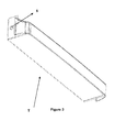
- At least one protrusion (6) provided on the carrier element (T) which can be used as shelf, tray, basket, etc. and perspective view of which is shown in Figure 3 is placed in the said recession (5) and the connection of the positioning component (K) to the carrier element (T) is ensured.
- the connection is ensured by placing at least one protrusion, which is on the said surface (K2) of the positioning element (K), in at least one recession on the carrier element (T).
- the home appliance in figures is exemplified as a cooling device and the carrier element is exemplified as a shelf which is provided on the door of the device and foods are placed thereon.
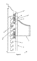
- FIG 4 an embodiment of the positioning element (K), the connection of which to the carrier element (T) is ensured, in the home appliance (cooling device) is shown.
- the positioning element (K) is placed in at least one channel (7), which is in at least one side surface (Y) of the device, (it is shown as the side surface (Y) at the door of the cooling device in the figures) via movement component (1) and protrusion (4) thereon and moves in the channel (7) by sliding.
- the movement component (1) is at the same axis with the protrusion (4), which is positioned in the channel (7), by means of fixing the movement component (1) to the connecting component (2) with swivel joint.
- the positioning element (K) can easily move in the channel (7).
- the protrusion (4) on the positioning element (K) is placed in at least one channel groove (8) as per this height.
- the channel groove (8) extends towards the side of the channel (7) and in the exemplary embodiment in figures; channel groove (8) extends towards the inside of the door (-X) of the device.
- the carrier element (T) reaching at desired height is moved towards the inside of the door (-X), as shown in Figure 5 , and the protrusion (4) is directed to the groove (8) thereon. Since the connecting compartment (2) is mounted to the movement compartment (1) and positioning element (K) with swivel joint, the carrier element (T) moves towards the inside of the door (-X) and the protrusion (4) is placed in desired groove (8), as shown in Figure 6 . Therefore, it is ensured that the carrier element (T) is fixed at desired height.
- the protrusion (4) reaches to the channel (7) by protruding from the groove (8) by means of moving the carrier element (T) outwards the door (+X).
- the carrier element (T) reaches at desired level by means of being moved by sliding in the channel (7) and the height of the carrier element (T) is adjusted via placing the protrusion (4) in the channel groove (8) at this height.
- the positioning element (K) comprises two movement compartments (1) in the exemplary embodiments shown in figures.
- the connecting compartments (2) which ensure the rotational movement of the movement compartments (1), are connected to one another by at least one elastic (flexible) element (9b) (i.e. spring) in an exemplary embodiment shown in Figure 7 .
- elastic (flexible) element (9b) i.e. spring
- connecting compartments (2) can move concurrently.
- the movement of the connecting compartments (2) can be limited by means of at least one another elastic (flexible) element (9a) positioned on the positioning element (K).
Landscapes
- Engineering & Computer Science (AREA)
- Chemical & Material Sciences (AREA)
- Combustion & Propulsion (AREA)
- Physics & Mathematics (AREA)
- Mechanical Engineering (AREA)
- Thermal Sciences (AREA)
- General Engineering & Computer Science (AREA)
- Domestic Plumbing Installations (AREA)
- Food-Manufacturing Devices (AREA)
- Casings For Electric Apparatus (AREA)
Abstract
The home appliance of the invention comprises at least one channel (7) provided on at least one side surface (Y); at least one channel groove (8) expanding to the side of the channel (7); at least one carrier element (T) positioned in the appliance via the channel (7); at least one movement component (1) which is connected to the carrier element (T), positioned on at least one surface (K1) and which moves slidably in the channel (7) ; at least one positioning element (K) which comprises at least one protrusion (4) placing in the said channel groove (8); at least one connecting component (2) which is fixed to the said surface (K1) of the positioning element (K) and to the movement component (1) with swivel joint.
Description
- The invention relates to home appliances comprising at least one carrier element, height of which can be adjusted.
- The position of the carrier elements, which are used in home appliances and provided on the inner surfaces of the sidewalls of the said appliance, which are used by being placed in the channels in certain distances according to one another, are fixed when the carrier element is placed in said channel. Thus, the user cannot move the position of the carrier element for a little upwardly or downwardly and can use the carrier element, which is placed according to the position of the channels in said appliance, at certain heights and the user can not adjust the height of the carrier element according to the needs.
- In the published patent application No
KR20020012443 - Another published patent application No
US2005274299A1 of the prior art discloses a two-piece apparatus which is fixed at the carrier element in order to adjust the height of the element. On one component of the said apparatus, protrusions are provided while on the other component of the apparatus, slots, in which protrusions are disposed, are provided. The component, on which the slot is provided, is fixed at the area of the device where the carrier element is positioned. The other component is fixed at the carrier element. Thus; the carrier element is positioned at desired height via the apparatus component fixed thereon. - The home appliance of the invention comprises at least one channel provided on at least one side surface; at least one channel groove expanding to the side of the channel; at least one carrier element positioned in the appliance via the channel; at least one movement component which is connected to the carrier element, positioned on at least one surface and which moves slidably in the channel; at least one positioning element which comprises at least one protrusion placing in the said channel groove; at least one connecting component which is fixed to the said surface of the positioning element with swivel joint and fixed to the movement component on the other side with swivel joint.
- The carrier element can move along the channel axis when the movement component and the protrusion are positioned in the channel. The carrier element reaching at desired height is moved towards the channel groove and the protrusion on the positioning element is placed in the channel groove at that height and the carrier element is fixed at that height. When the height of the carrier element is wanted to be changed, the carrier element is moved so as to be moved away from the channel groove and the protrusion arrives the channel via protruding out of the groove and thus; the carrier element can move along the channel. When the carrier element reaches at desired height, the protrusion is placed in the channel groove at that height and the carrier element is fixed at that height.
- The aim of the invention is to develop a home appliance which comprises a carrier element, the height of which is adjustable.
- The other aim of the invention is to develop a home appliance, the height of which is easily adjustable even when weight is placed thereon.
- Another aim of the invention is to develop a home appliance, the height of which is adjustable in a balanced way.
- A further aim of the invention is to develop a reliable and cost-effective carrier element which is easily produced, assembled and used.
- An exemplary carrier element and an exemplary positioning element used thereon are shown in annexed drawings and:
-
Figure 1 is the perspective view of the one face of the positioning element. -
Figure 2 is the frontal view of the other face of the positioning element. -
Figure 3 is the perspective view of the carrier element. -
Figure 4 is the sectional side view of the embodiment of the carrier element in an exemplary home appliance. -
Figure 5 is the sectional side view of the carrier element in another position. -
Figure 6 is the sectional view of the carrier element in another position. -
Figure 7 is the perspective view of the other embodiment of the positioning element. - The parts in the figures are individually enumerated and the corresponding terms of reference numbers are as follows:
Positioning element (K) Surface (K1, K2) Carrier element (T) Side surface (Y) Movement component (1) Connecting component (2) Connecting element (3) Protrusion (4,6) Recession (5) Channel (7) Channel groove (8) Elastic element (9a, 9b) - The positioning element (K) of the shown invention comprises at least one movement component (1), which is positioned on at least one surface (K1) of this element, and at least one protrusion (4).
- The positioning element (K), an exemplary embodiment of which is shown in
Figure 1 , comprises at least one connecting component (2) which is fixed with swivel joint at the said surface (K1) from at least one side and which is fixed with swivel joint at the movement component (1) from another side. The connecting component (2) is fixed at the positioning element (K) via at least one connecting element (3). The connecting element (3) can be protrusion on the positioning element (K) or a component such as screw. At least one protrusion (4) is provided on said surface (K1) of the element (K). - An exemplary positioning element (K), another surface (K2) of which is shown in
Figure 2 , comprises at least one recession (5) on this surface (K2). At least one protrusion (6) provided on the carrier element (T) which can be used as shelf, tray, basket, etc. and perspective view of which is shown inFigure 3 , is placed in the said recession (5) and the connection of the positioning component (K) to the carrier element (T) is ensured. In another embodiment of the invention, which is not shown in figures, the connection is ensured by placing at least one protrusion, which is on the said surface (K2) of the positioning element (K), in at least one recession on the carrier element (T). - In order to disclose operating principle of the positioning element (K), the home appliance in figures is exemplified as a cooling device and the carrier element is exemplified as a shelf which is provided on the door of the device and foods are placed thereon.
- In
figure 4 , an embodiment of the positioning element (K), the connection of which to the carrier element (T) is ensured, in the home appliance (cooling device) is shown. The positioning element (K) is placed in at least one channel (7), which is in at least one side surface (Y) of the device, (it is shown as the side surface (Y) at the door of the cooling device in the figures) via movement component (1) and protrusion (4) thereon and moves in the channel (7) by sliding. - In the exemplary embodiments in
Figures 4-7 , the movement component (1) is at the same axis with the protrusion (4), which is positioned in the channel (7), by means of fixing the movement component (1) to the connecting component (2) with swivel joint. Thus, the positioning element (K) can easily move in the channel (7). When the carrier element (T) reaches at desired height, the protrusion (4) on the positioning element (K) is placed in at least one channel groove (8) as per this height. The channel groove (8) extends towards the side of the channel (7) and in the exemplary embodiment in figures; channel groove (8) extends towards the inside of the door (-X) of the device. The carrier element (T) reaching at desired height is moved towards the inside of the door (-X), as shown inFigure 5 , and the protrusion (4) is directed to the groove (8) thereon. Since the connecting compartment (2) is mounted to the movement compartment (1) and positioning element (K) with swivel joint, the carrier element (T) moves towards the inside of the door (-X) and the protrusion (4) is placed in desired groove (8), as shown inFigure 6 . Therefore, it is ensured that the carrier element (T) is fixed at desired height. - When the height of the carrier element (T), which is positioned in the device, is wanted to be changed, the protrusion (4) reaches to the channel (7) by protruding from the groove (8) by means of moving the carrier element (T) outwards the door (+X). The carrier element (T) reaches at desired level by means of being moved by sliding in the channel (7) and the height of the carrier element (T) is adjusted via placing the protrusion (4) in the channel groove (8) at this height.
- The positioning element (K) comprises two movement compartments (1) in the exemplary embodiments shown in figures. The connecting compartments (2), which ensure the rotational movement of the movement compartments (1), are connected to one another by at least one elastic (flexible) element (9b) (i.e. spring) in an exemplary embodiment shown in
Figure 7 . Thus, connecting compartments (2) can move concurrently. In addition, the movement of the connecting compartments (2) can be limited by means of at least one another elastic (flexible) element (9a) positioned on the positioning element (K).
Claims (6)
- A home appliance comprising at least one channel (7) provided on at least one side surface (Y); at least one channel groove (8) expanding to the side of the channel (7); at least one carrier element (T) positioned in the appliance via the channel (7) characterized by comprising;- at least one movement component (1) which is connected to the carrier element (T), positioned on at least one surface (K1) and which moves slidably in the channel (7) ; at least one positioning element (K) which comprises at least one protrusion (4) placing in said channel groove (8);- at least one connecting component (2) which is fixed to the said surface (K1) of the positioning element (K) with swivel joint and fixed to the movement component (1) on the other side with swivel joint .
- A home appliance according to Claim 1 characterized by comprising at least one connecting element (3) which fixes said connecting component (2) to the positioning element (K).
- A home appliance according to Claim 1 characterized by comprising at least one protrusion (6) on the carrier element (T).
- A home appliance according to Claim 1 characterized by comprising at least one recession (5) which is provided on at least one surface (K2) of the positioning element (K) and said protrusion (6) is placed therein.
- A home appliance according to Claim 1 characterized by comprising at least one another protrusion which is provided on at least one another surface (K2) of the positioning element (K).
- A home appliance according to Claim 5 characterized by comprising at least one recession which is provided on carrier element (T) and said protrusion is placed therein.
Applications Claiming Priority (1)
| Application Number | Priority Date | Filing Date | Title |
|---|---|---|---|
| TR2010/07207A TR201007207A2 (en) | 2010-08-27 | 2010-08-27 | A household appliance containing a carrier element. |
Publications (1)
| Publication Number | Publication Date |
|---|---|
| EP2423625A2 true EP2423625A2 (en) | 2012-02-29 |
Family
ID=44658627
Family Applications (1)
| Application Number | Title | Priority Date | Filing Date |
|---|---|---|---|
| EP11177008A Withdrawn EP2423625A2 (en) | 2010-08-27 | 2011-08-09 | A home appliance comprising a carrier element |
Country Status (2)
| Country | Link |
|---|---|
| EP (1) | EP2423625A2 (en) |
| TR (1) | TR201007207A2 (en) |
Cited By (1)
| Publication number | Priority date | Publication date | Assignee | Title |
|---|---|---|---|---|
| CN108120218A (en) * | 2017-11-29 | 2018-06-05 | 青岛海尔股份有限公司 | A kind of refrigerator |
Citations (2)
| Publication number | Priority date | Publication date | Assignee | Title |
|---|---|---|---|---|
| KR20020012443A (en) | 2000-08-07 | 2002-02-16 | 구자홍 | The mounting structure for door basket of refrigerators |
| US20050274299A1 (en) | 2003-01-31 | 2005-12-15 | Craig Bienick | Refrigerator compartment housing vertically adjustable shelves |
-
2010
- 2010-08-27 TR TR2010/07207A patent/TR201007207A2/en unknown
-
2011
- 2011-08-09 EP EP11177008A patent/EP2423625A2/en not_active Withdrawn
Patent Citations (2)
| Publication number | Priority date | Publication date | Assignee | Title |
|---|---|---|---|---|
| KR20020012443A (en) | 2000-08-07 | 2002-02-16 | 구자홍 | The mounting structure for door basket of refrigerators |
| US20050274299A1 (en) | 2003-01-31 | 2005-12-15 | Craig Bienick | Refrigerator compartment housing vertically adjustable shelves |
Cited By (2)
| Publication number | Priority date | Publication date | Assignee | Title |
|---|---|---|---|---|
| CN108120218A (en) * | 2017-11-29 | 2018-06-05 | 青岛海尔股份有限公司 | A kind of refrigerator |
| CN108120218B (en) * | 2017-11-29 | 2020-05-08 | 青岛海尔股份有限公司 | a refrigerator |
Also Published As
| Publication number | Publication date |
|---|---|
| TR201007207A2 (en) | 2010-12-21 |
Similar Documents
| Publication | Publication Date | Title |
|---|---|---|
| EP2159523A1 (en) | Refrigeration equipment and console system for use therein | |
| CN101815914B (en) | Offset Loaded Slider | |
| CN104344671B (en) | Refrigerator and drawer component thereof | |
| US9347704B2 (en) | Refrigerated drawer and divider assembly therefor | |
| GB2471418A (en) | Seperating frame group structure of drawer | |
| AU2014410494B2 (en) | Improved shelf assembly and refrigeration appliance having the same | |
| EP2042811B1 (en) | Telescopic rail system | |
| US20200281401A1 (en) | Oven based non-powered accessory system | |
| KR20170107664A (en) | Multi-functional rack with wall fixed type | |
| WO2013098257A1 (en) | A cooling device comprising a height adjustable shelf | |
| EP2423625A2 (en) | A home appliance comprising a carrier element | |
| EP1563762B1 (en) | Easy height adjustment device for refrigerator shelves | |
| US9788651B1 (en) | Consolidated kitchen workspace | |
| US20160113479A1 (en) | Dish rack | |
| WO2016087083A1 (en) | A cooling device comprising a height adjustable shelf | |
| CN105979819A (en) | Cabinet drawer | |
| CN108443921B (en) | Apparatus for fitting a carrier element of an article into a body | |
| JP2010148788A (en) | Frying pan rack | |
| EP3141850B1 (en) | A shelf system | |
| CN203758154U (en) | Refrigerator and drawer module thereof | |
| US10962278B2 (en) | Mounting systems for refrigeration devices | |
| US10309658B2 (en) | Kitchen workspace with a moving oven | |
| JP6552311B2 (en) | Storage rack for cookware | |
| WO2008080943A1 (en) | A refrigerator | |
| EP1960217B1 (en) | A household appliance |
Legal Events
| Date | Code | Title | Description |
|---|---|---|---|
| AK | Designated contracting states |
Kind code of ref document: A2 Designated state(s): AL AT BE BG CH CY CZ DE DK EE ES FI FR GB GR HR HU IE IS IT LI LT LU LV MC MK MT NL NO PL PT RO RS SE SI SK SM TR |
|
| AX | Request for extension of the european patent |
Extension state: BA ME |
|
| PUAI | Public reference made under article 153(3) epc to a published international application that has entered the european phase |
Free format text: ORIGINAL CODE: 0009012 |
|
| STAA | Information on the status of an ep patent application or granted ep patent |
Free format text: STATUS: THE APPLICATION IS DEEMED TO BE WITHDRAWN |
|
| 18D | Application deemed to be withdrawn |
Effective date: 20140301 |