EP2159523A1 - Refrigeration equipment and console system for use therein - Google Patents
Refrigeration equipment and console system for use therein Download PDFInfo
- Publication number
- EP2159523A1 EP2159523A1 EP08015342A EP08015342A EP2159523A1 EP 2159523 A1 EP2159523 A1 EP 2159523A1 EP 08015342 A EP08015342 A EP 08015342A EP 08015342 A EP08015342 A EP 08015342A EP 2159523 A1 EP2159523 A1 EP 2159523A1
- Authority
- EP
- European Patent Office
- Prior art keywords
- section
- side wall
- side section
- groove
- console system
- Prior art date
- Legal status (The legal status is an assumption and is not a legal conclusion. Google has not performed a legal analysis and makes no representation as to the accuracy of the status listed.)
- Granted
Links
Images


Classifications
-
- F—MECHANICAL ENGINEERING; LIGHTING; HEATING; WEAPONS; BLASTING
- F25—REFRIGERATION OR COOLING; COMBINED HEATING AND REFRIGERATION SYSTEMS; HEAT PUMP SYSTEMS; MANUFACTURE OR STORAGE OF ICE; LIQUEFACTION SOLIDIFICATION OF GASES
- F25D—REFRIGERATORS; COLD ROOMS; ICE-BOXES; COOLING OR FREEZING APPARATUS NOT OTHERWISE PROVIDED FOR
- F25D23/00—General constructional features
- F25D23/06—Walls
- F25D23/065—Details
- F25D23/067—Supporting elements
-
- A—HUMAN NECESSITIES
- A47—FURNITURE; DOMESTIC ARTICLES OR APPLIANCES; COFFEE MILLS; SPICE MILLS; SUCTION CLEANERS IN GENERAL
- A47B—TABLES; DESKS; OFFICE FURNITURE; CABINETS; DRAWERS; GENERAL DETAILS OF FURNITURE
- A47B88/00—Drawers for tables, cabinets or like furniture; Guides for drawers
- A47B88/40—Sliding drawers; Slides or guides therefor
- A47B88/417—Profiled cabinet walls with grooves or protuberances for supporting drawers
-
- A—HUMAN NECESSITIES
- A47—FURNITURE; DOMESTIC ARTICLES OR APPLIANCES; COFFEE MILLS; SPICE MILLS; SUCTION CLEANERS IN GENERAL
- A47B—TABLES; DESKS; OFFICE FURNITURE; CABINETS; DRAWERS; GENERAL DETAILS OF FURNITURE
- A47B88/00—Drawers for tables, cabinets or like furniture; Guides for drawers
- A47B88/40—Sliding drawers; Slides or guides therefor
- A47B88/423—Fastening devices for slides or guides
- A47B88/43—Fastening devices for slides or guides at cabinet side
-
- F—MECHANICAL ENGINEERING; LIGHTING; HEATING; WEAPONS; BLASTING
- F25—REFRIGERATION OR COOLING; COMBINED HEATING AND REFRIGERATION SYSTEMS; HEAT PUMP SYSTEMS; MANUFACTURE OR STORAGE OF ICE; LIQUEFACTION SOLIDIFICATION OF GASES
- F25D—REFRIGERATORS; COLD ROOMS; ICE-BOXES; COOLING OR FREEZING APPARATUS NOT OTHERWISE PROVIDED FOR
- F25D25/00—Charging, supporting, and discharging the articles to be cooled
- F25D25/02—Charging, supporting, and discharging the articles to be cooled by shelves
- F25D25/024—Slidable shelves
- F25D25/025—Drawers
-
- A—HUMAN NECESSITIES
- A47—FURNITURE; DOMESTIC ARTICLES OR APPLIANCES; COFFEE MILLS; SPICE MILLS; SUCTION CLEANERS IN GENERAL
- A47B—TABLES; DESKS; OFFICE FURNITURE; CABINETS; DRAWERS; GENERAL DETAILS OF FURNITURE
- A47B2210/00—General construction of drawers, guides and guide devices
- A47B2210/17—Drawers used in connection with household appliances
- A47B2210/175—Refrigerators or freezers
Definitions
- the present disclosure relates to a refrigeration equipment, in particular a kitchen appliance, such as a refrigerator
- the refrigeration equipment comprises an inner space for receiving objects that are to be refrigerated, the inner space is partly defined by two opposite side walls, the side walls are arranged with several side grooves.
- the refrigeration equipment further comprises a console system arranged to attach a storage unit to the side grooves in the inner space.
- the present disclosure further relates to a console system for mounting of storage units in a refrigeration equipment.
- a refrigeration equipment in particular a kitchen appliance, such as a refrigerator or a freezer, is used in order to refrigerate objects, for example different kind of provisions, in an inner space of the refrigeration equipment.
- a top part, a bottom part, a rear portion, a front portion (comprising a door arranged to make it possible to close the refrigerator) and two opposite side walls define the inner space.
- the walls of the inner space are arranged with side grooves to receive shelves on which the provisions can be kept.
- a pair of drawers for keeping, for example, vegetables are often placed on the bottom part of the inner space with no connection to the side grooves.
- EP 1 030 146 shows a prior art system wherein guides in the form of lateral bearer arms of a U-shaped bearer frame are removably attached to the side walls of a cold chamber. At least one shelf is movably mounted in the guides to slide like a drawer. An arrangement according to EP 1 030 146 is solely adapted for shelves.
- US 2005156494 shows a refrigerator including a universal crisper pan, a drawer for keeping vegetables, and support frame.
- the frame is adapted to support various different shelving units and to slidably receive a crisper pan.
- the frame bear upon projections in the inner side walls of the refrigerator.
- a support frame according to US 2005156494 is quite complicated, includes many different parts, and results therefore in an expensive and ungainly system.
- a refrigeration equipment comprising a first and a second side wall opposite to each other, defining between them an inner space for receiving items to be refrigerated and having a plurality of side grooves, and a console system arranged to couple a storage unit to the side grooves in the inner space, the console system comprising a first and a second side section substantially parallel with each other and designed for sliding engagement with the storage unit; each side section comprises a first portion and a second portion, wherein:
- each side section By designing the first portion of each side section substantially horizontal and the second portion substantially vertical, preferably in direction downwards from the first portion, it is possible to arrange each side section in two different grooves which are arranged on two different levels. This arrangement results in a console system having two different attachments points, on two different levels, which results in an even more stable construction.
- the console system By arranging the console system with at least one crosspiece extending from the first side section to the second side section a stable construction which demands a small amount of material is achieved.
- the crosspiece makes it possible to keep a fixed distance between the first side section and the second side section, which makes the drawer run smoothly since the crosspiece prevents the drawer from getting stuck if the distance between the inner side walls should change due to vartions in the material.
- each side section By arranging the first portion of each side section with a sliding part for sliding engagement with the storage unit, and an attachment part for attaching the console system to the walls delimiting the inner space makes it possible to achieve a smooth drawer movement without wearing the inner side walls of the refrigeration equipment.
- the drawer in its lower part, close to the bottom part, is arranged with a guide on each side, which guides are adapted for sliding engagement with the sliding parts of the first side sections, it is possible to construct the side sections from simple and quite small parts.
- the side sections, the crosspiece and the guides are all placed close to each other, which results in a very stable construction.
- a console system comprising a first and a second side section, wherein a second portion of each of the first side sections is arranged in a second side groove of the first side wall of the refrigeration equipment, so that a stable and secure console system is achieved.
- the crosspiece is adapted to fix the side sections of the console system to the side grooves of the inner walls of the refrigeration equipment. This construction results in that the pick-up efficiency of tolerance increases with the depth of the side grooves.
- a refrigeration equipment 1 is shown.
- the refrigeration equipment is in particular a kitchen appliance, such as a refrigerator.
- the refrigeration equipment 1 comprises an inner space 10 for receiving objects that are to be refrigerated.
- a top part 10a, a bottom part 10b, a rear portion 11, a front portion (comprising a door arranged to make it possible to close the refrigerator, not shown) and two opposite side walls 12, 13 define the inner space 10.
- the side walls 12, 13 can be slightly vaulted, in such a way that the inner space, when looking into the inner space 10 in direction from the front portion towards the rear portion 11, can be slightly hourglass shaped.
- the inner side walls 12, 13 are made of plastic material such as HIPS (High Impact Polystyrene), or other materials suitable for the purpose.
- the inner side walls 12, 13 holds a hollow space that during fabrication are filled with a compound of chemicals that rises and cures and thereby forms a solid foam.
- the hourglass shape can occur due to the fact that this chemical process might be not completed, i.e. the foam might not have reached its final solidifying point, when the refrigerators are put together.
- the inner side walls 12, 13 can therefore take a slightly vaulted shape since the material is still moving.
- the material of the inner side walls 12, 13 can also move, during use, due to temperature variations in the refrigerator.
- the opposite side walls 12, 13 are arranged in a conventional way and show several side grooves 14 for receiving at least one conventional storage unit (or element) 15.
- the conventional storage unit 15 is often a shelf but can also be, where appropriate, a drawer.
- the drawers are otherwise often placed on the bottom of the inner space 10, with no connection to the grooves 14.
- the side grooves 14a, 14b advantageously have an elongated shape and extend, substantially horizontal, over each opposite side wall 12, 13.
- the side grooves 14a, 14b may also have different shapes.
- the second side groove 14b is arranged immediately underneath the first side groove 14a.
- FIG. fig 3a-3b shows a console system 20, which is arranged to couple a storage unit 24 to the side grooves 14 in the inner space 10, see figures 4a-4b .
- the storage unit 24 is advantageously a drawer, a tray or similar, and for the sake of simplicity the storage unit 24 will henceforth be referred to as a drawer 24, described more in detail below.
- the console system 20 comprises a first side section 21 and a second side section 22, which side sections 21, 22 have an elongated shape and are adapted to be arranged substantially parallel with each other in the inner space 10.
- the first side section 21 is arranged to be coupled to the first side wall 12.
- the second side section 22 is arranged to be coupled to the second side wall 13.
- the first side section 21 comprises a first portion 211 and a second portion 212.
- the second side section 22 comprises a first portion 221 and a second portion 222.
- the first portion 211, 221 of ech side section 21, 22 has an elongated shape and extends, when arranged inside the inner space 10, substantially horizontal over the side walls 12, 13, in direction from the front portion/the door (not shown) towards the rear portion 11.
- the second portion 212, 222 is substantially square-shaped and extends substantially vertical, downwards, from the first portion 211, 221.
- the first portion 211, 221 of each side section 21, 22 comprises a gliding part 211a, 221 a for sliding engagement with the drawer 24.
- a glide system such as a friction, roller or ball bearing glide system can be used as gliding part 211 a, 221 a.
- the first portion 211, 221 further comprises an attachment part 211 b, 221 b for coupling the console system 20 to the inner space 10.
- the attachment part 211 b, 221 b and the sliding part 211 a, 221 a are attached to each other by means of some kind of attachment devices, such as screws or the like, see fig 3a .
- the first portion 211, 221 of each of the at least first 21 and second 22 side section 12, 13 is arranged in a first side groove 14a in each opposite side wall 12, 13.
- the second portion 212, 222 of each of the at least first 21 and second 22 side section is arranged in a second side groove 14b in each opposite side wall 12, 13.
- the second side groove 14b is preferably arranged immediately underneath the first side groove 14a in each opposite side wall 12, 13.
- the second portion 212, 222 is extending downwards from the first portion 211, 221 such that the second groove 14b to which the second portion 212, 222 is to be coupled is not the groove immediately underneath the first side groove 14a, but a groove that is one or several grooves downwards from the first groove 14a.
- the second portion 212, 222 is extending upwards from the first portion 211, 221 such that the second groove 14b to which the second portion 212, 222 is to be coupled is not the groove immediately underneath the first side groove 14a, but the groove immediately above the first groove or a groove that is one or several grooves upwards from the first groove 14a.
- the attachment part 211 b, 221 b on each side section 21, 22 is removably coupled to the side grooves 14a on each opposite side wall 12, 13. Thanks to their shape, the attachment parts 211 b, 221 b allow a snap-in coupling with the side grooves 14a.
- the console system 20 comprises at least one crosspiece 23, which has an elongated shape and extends from the first side section 21 to the second side section 22 for keeping the side sections 21, 22 apart from each other (at a fixed distance) and close or in contact with the opposite side walls 12, 13 (in particular, the first side section 21 towards the first side wall 12 and the second side section 22 towards the second side wall 13).
- the crosspiece 23 is more specifically arranged between the second portion 212 of the first side section 21 and the second portion 222 of the second side section 22.
- Each of the second portions 212, 222 has a recess 212a, 222a for receiving the crosspiece 23.
- Each of the second portions 212, 222 has also a projection 212b, 222b shaped (in cross-section) as the attachment part 211 b, 221 b.
- the projection 212b is designed to be arranged into the second side groove 14b on the first side wall 12 and the projection 222b is designed to be arranged into the second side groove 14b on the second side wall 13.
- the side sections 21, 22 and the crosspiece 23 can be advantageously moulded by using different kinds of plastic materials, or may be made of metal, preferably aluminium, or partly of plastic and partly of metal (aluminium), or other suitable materials.
- the drawer 24 is of conventional kind, but it is suitable for gliding in the gliding part 211 a, 221 a of the console system 20, see figures 4a-4b .
- the drawer 24 is defined by a front 241, a back 242, a bottom 243 and two side pieces 244, 245.
- the outer surface of the side pieces 244, 245 is, in the lower part, i.e. close to the bottom part 243, arranged with a guide 246 on each side piece 244, 245.
- the guides 246 are adapted for sliding engagement with the sliding parts 211 a, 221 a.
Abstract
Description
- The present disclosure relates to a refrigeration equipment, in particular a kitchen appliance, such as a refrigerator, the refrigeration equipment comprises an inner space for receiving objects that are to be refrigerated, the inner space is partly defined by two opposite side walls, the side walls are arranged with several side grooves. The refrigeration equipment further comprises a console system arranged to attach a storage unit to the side grooves in the inner space.
- The present disclosure further relates to a console system for mounting of storage units in a refrigeration equipment.
- A refrigeration equipment, in particular a kitchen appliance, such as a refrigerator or a freezer, is used in order to refrigerate objects, for example different kind of provisions, in an inner space of the refrigeration equipment. A top part, a bottom part, a rear portion, a front portion (comprising a door arranged to make it possible to close the refrigerator) and two opposite side walls define the inner space.
- In such refrigerator equipments the walls of the inner space are arranged with side grooves to receive shelves on which the provisions can be kept. A pair of drawers for keeping, for example, vegetables are often placed on the bottom part of the inner space with no connection to the side grooves.
- In order to receive a more flexible refrigerator interior which makes it possible for the user to place shelves and drawers according to individually needs and requirements, it is known to provide shelves and drawers, in the inner space of a refrigeration equipment, by means of removably attached console systems.
-
EP 1 030 146EP 1 030 146 -
US 2005156494 shows a refrigerator including a universal crisper pan, a drawer for keeping vegetables, and support frame. The frame is adapted to support various different shelving units and to slidably receive a crisper pan. The frame bear upon projections in the inner side walls of the refrigerator. A support frame according toUS 2005156494 is quite complicated, includes many different parts, and results therefore in an expensive and ungainly system. - Compared to the prior art arrangements described above there is a need for a refrigeration equipment having a cost-effective console system, for receiving shelves or drawers, which is not only detachably attached to the side walls of the inner space, in a non-destructive way, but also has a durable, stable and secure construction, even though the shelves and/or drawers are heavy loaded.
- The above defined problems are at least substantially solved by a refrigeration equipment comprising a first and a second side wall opposite to each other, defining between them an inner space for receiving items to be refrigerated and having a plurality of side grooves, and a console system arranged to couple a storage unit to the side grooves in the inner space, the console system comprising a first and a second side section substantially parallel with each other and designed for sliding engagement with the storage unit; each side section comprises a first portion and a second portion, wherein:
- the first portion of the first side section is arranged in a first side groove in the first side wall,
- the first portion of the second side section is arranged in a first side groove in the second side wall,
- the second portion of the first side section is arranged in a second side groove in the first side wall, and the second portion of the second side section is arranged in a second side groove in the second side wall.
- By designing the side sections such that it is possible to couple them to two different side grooves a very durable console system is achieved since the system has two different attachments points, which results in a stable construction.
- By designing the first portion of each side section substantially horizontal and the second portion substantially vertical, preferably in direction downwards from the first portion, it is possible to arrange each side section in two different grooves which are arranged on two different levels. This arrangement results in a console system having two different attachments points, on two different levels, which results in an even more stable construction.
- By arranging the console system with at least one crosspiece extending from the first side section to the second side section a stable construction which demands a small amount of material is achieved. The crosspiece makes it possible to keep a fixed distance between the first side section and the second side section, which makes the drawer run smoothly since the crosspiece prevents the drawer from getting stuck if the distance between the inner side walls should change due to vartions in the material.
- By arranging the first portion of each side section with a sliding part for sliding engagement with the storage unit, and an attachment part for attaching the console system to the walls delimiting the inner space makes it possible to achieve a smooth drawer movement without wearing the inner side walls of the refrigeration equipment.
- By arranging the attachment part on each side section detachably to the side grooves on each opposite side wall it is easy to move the shelves and/or drawers between the side grooves inside the inner space of the refrigeration equipment without effecting the side walls.
- Since the drawer in its lower part, close to the bottom part, is arranged with a guide on each side, which guides are adapted for sliding engagement with the sliding parts of the first side sections, it is possible to construct the side sections from simple and quite small parts. The side sections, the crosspiece and the guides are all placed close to each other, which results in a very stable construction.
- By arranging the side grooves with an elongated shape which extends, substantially horizontal, over each opposite side wall, a quite large attachment surface is achieved which improves the adhesive capacity, since the drawer also has an as large attachment surface.
- According to another aspect of the invention, a console system is claimed comprising a first and a second side section, wherein a second portion of each of the first side sections is arranged in a second side groove of the first side wall of the refrigeration equipment, so that a stable and secure console system is achieved.
- By arranging the console system with at least one crosspiece an even more stable construction is achieved. The crosspiece is adapted to fix the side sections of the console system to the side grooves of the inner walls of the refrigeration equipment. This construction results in that the pick-up efficiency of tolerance increases with the depth of the side grooves.
- The invention will in the following be described in more detail with reference to the enclosed drawings, wherein:
-
Fig 1a schematically illustrates a perspective view of a refrigeration equipment, and a console system, arranged to attach a storage unit to side grooves in an inner space of the refrigeration equipment. -
Fig 1b schematically illustrates a perspective view of the refrigeration equipment infig 1a , when the console system is arranged therein. -
Fig 1c schematically illustrates a perspective view of the refrigeration equipment infig 1b , and a drawer adapted to be arranged therein. -
Fig 1d schematically illustrates a perspective view of the refrigeration equipment infig 1c , when the drawer is arranged therein. -
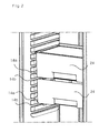
Fig 2 schematically illustrates a perspective view of an embodiment of the refrigeration equipment, wherein two drawers are arranged in the inner space. -
Fig 3a schematically illustrates a perspective view of a console system comprising two side sections and a cross piece. -
Fig 3b schematically illustrates a perspective view of the console system infig 3a , seen from the front. -
Fig 4a schematically illustrates a perspective view of a console system, a drawer and a shelf adapted to be arranged to interact with one another. -
Fig 4b schematically illustrates a perspective view of the including parts infig 4a , wherein the parts are arranged together. - The present invention will be described in more detail hereinafter with reference to the accompanying drawings, in which a preferred embodiment of the invention is shown. This invention may, however, be embodied in many different forms and should not be construed as limited to the embodiment set forth herein; rather, the embodiment is provided so that this disclosure will be thorough and complete, and will fully convey the scope of the invention to those skilled in the art. In the drawings, like numbers refer to like elements. In the embodiment of the invention described in the figures, a
refrigeration equipment 1, is shown. The refrigeration equipment is in particular a kitchen appliance, such as a refrigerator. - The
refrigeration equipment 1 comprises aninner space 10 for receiving objects that are to be refrigerated. Atop part 10a, abottom part 10b, a rear portion 11, a front portion (comprising a door arranged to make it possible to close the refrigerator, not shown) and twoopposite side walls inner space 10. Theside walls inner space 10 in direction from the front portion towards the rear portion 11, can be slightly hourglass shaped. - The
inner side walls inner side walls inner side walls inner side walls - The
opposite side walls conventional storage unit 15 is often a shelf but can also be, where appropriate, a drawer. The drawers are otherwise often placed on the bottom of theinner space 10, with no connection to the grooves 14. - The
side grooves opposite side wall side grooves side grooves second side groove 14b is arranged immediately underneath thefirst side groove 14a. - Figures
fig 3a-3b shows aconsole system 20, which is arranged to couple astorage unit 24 to the side grooves 14 in theinner space 10, seefigures 4a-4b . Thestorage unit 24 is advantageously a drawer, a tray or similar, and for the sake of simplicity thestorage unit 24 will henceforth be referred to as adrawer 24, described more in detail below. - The
console system 20 comprises afirst side section 21 and asecond side section 22, whichside sections inner space 10. Thefirst side section 21 is arranged to be coupled to thefirst side wall 12. Thesecond side section 22 is arranged to be coupled to thesecond side wall 13. - The
first side section 21 comprises afirst portion 211 and asecond portion 212. Thesecond side section 22 comprises afirst portion 221 and asecond portion 222. Thefirst portion ech side section inner space 10, substantially horizontal over theside walls second portion first portion - The
first portion side section gliding part drawer 24. A glide system, such as a friction, roller or ball bearing glide system can be used as glidingpart first portion attachment part console system 20 to theinner space 10. Theattachment part part fig 3a . - The
first portion side section first side groove 14a in eachopposite side wall second portion second side groove 14b in eachopposite side wall second side groove 14b is preferably arranged immediately underneath thefirst side groove 14a in eachopposite side wall - In one possible embodiment of the invention the
second portion first portion second groove 14b to which thesecond portion first side groove 14a, but a groove that is one or several grooves downwards from thefirst groove 14a. - In another embodiment of the invention the
second portion first portion second groove 14b to which thesecond portion first side groove 14a, but the groove immediately above the first groove or a groove that is one or several grooves upwards from thefirst groove 14a. - The
attachment part side section side grooves 14a on eachopposite side wall attachment parts side grooves 14a. - The
console system 20 comprises at least onecrosspiece 23, which has an elongated shape and extends from thefirst side section 21 to thesecond side section 22 for keeping theside sections opposite side walls 12, 13 (in particular, thefirst side section 21 towards thefirst side wall 12 and thesecond side section 22 towards the second side wall 13). Thecrosspiece 23 is more specifically arranged between thesecond portion 212 of thefirst side section 21 and thesecond portion 222 of thesecond side section 22. Each of thesecond portions recess crosspiece 23. Each of thesecond portions projection attachment part projection 212b is designed to be arranged into thesecond side groove 14b on thefirst side wall 12 and theprojection 222b is designed to be arranged into thesecond side groove 14b on thesecond side wall 13. - The
side sections crosspiece 23 can be advantageously moulded by using different kinds of plastic materials, or may be made of metal, preferably aluminium, or partly of plastic and partly of metal (aluminium), or other suitable materials. - The
drawer 24 is of conventional kind, but it is suitable for gliding in thegliding part console system 20, seefigures 4a-4b . Thedrawer 24 is defined by a front 241, a back 242, a bottom 243 and twoside pieces side pieces bottom part 243, arranged with aguide 246 on eachside piece guides 246 are adapted for sliding engagement with the slidingparts - In the drawings and specification, there have been disclosed preferred embodiments and examples of the invention and, although specific terms are employed, they are used in a generic and descriptive sense only and not for the purpose of limitation, the scope of the invention being set forth in the following claims.
Claims (9)
- Refrigeration equipment, in particular a kitchen appliance, such as a refrigerator, comprising:a first side wall (12) and a second side wall (13) defining between them an inner space (10) for receiving items to be refrigerated, the side walls (12, 13) being arranged opposite to each other and having a plurality of side grooves (14a, 14b),a console system (20) arranged to couple a storage unit (24) to the side grooves (14a, 14b) in the inner space (10), the console system (20) comprising a first and a second side section (21, 22) substantially parallel with each other and designed for sliding engagement with the storage unit (24),
characteized in that:each of the first and the second side sections (21, 22) comprises a first portion (211, 221) and a second portion (212, 222),
wherein the first portion (211) of the first side section (21) is arranged in a first side groove (14a) in the first side wall (12), and the first portion (221) of the second side section (22) is arranged in a first side groove (14a) in the second side wall (13), and
wherein the second portion (212) of the first side section (21) is arranged in a second side groove (14b) in the first side wall (12), and the second portion (222) of the second side section (22) is arranged in a second side groove (14b) in the second side wall (13). - The refrigeration system according to claim 1, wherein the first portion (211, 221) of each side section (21, 22) extends substantially horizontal, and wherein the second portion (212, 222) of each side section (21, 22) extends substantially vertical from the first portion (211, 221).
- The refrigeration system according to claim 1 or 2, wherein the console system (20) comprises at least one crosspiece (23) extending between the first side section (21) and the second side section (22) for keeping the first side section (21) close to, or in contact with, the first side wall (12), and the second side section (13) close to, or in contact with, the second side wall (13).
- The refrigeration system according to claim 3, wherein the crosspiece (23) is arranged between the second portion (212) of the first side section (21) and the second portion (222) of the second side section (22).
- The refrigeration system according to any one of the preceding claims, wherein the first portion (211, 221) of each side section (21, 22) comprises a sliding part (211 a, 221 a) for sliding engagement with the storage unit (24), and an attachment part (211 b, 221 b) for coupling the console system (20) to the first and second side walls (12, 13).
- The refrigeration system according to claim 5, wherein the attachment part (211 b) on the first side section (21) is removably coupled to the first side groove (14a) on the first side wall (12), and the attachment part (221 b) on the second side section (22) is removably coupled to the first side groove (14a) on the second side wall (13).
- The refrigeration system according to any one of the preceding claims, wherein the side grooves (14a, 14b) have an elongated shape and extend, substantially horizontal, over each opposite side wall (21, 22).
- Console system for mounting of storage units (24) in a refrigeration equipment (1), the console system (20) comprises a first side section (21) and a second side section (22) that are adapted to be coupled to a first side wall (12) and, respectively, to a second side wall (13) in an inner space (10) of the refrigeration equipment (1), said side sections (21, 22) being substantially parallel with each other and being adapted for sliding engagement with a storage unit (24),
characteized in that
a first portion (211) of the first side section (21) is adapted to be arranged in a first side groove (14a) in the first side wall (12),
a first portion (221) of the second side section (22) is adapted to be arranged in a first side groove (14a) in the second side wall (13),
a second portion (212) of the first side section (21) is adapted to be arranged in a second side groove (14b) in the first side wall (12), and
a second portion (222) of the second side section (22) is adapted to be arranged in a second side groove (14b) in the second side wall (13). - A console system as claimed in claim 8, comprising at least one crosspiece (23) extending from the first side section (21) to the second side section (22), the crosspiece (23) being adapted for forcing the first side section (21) against the first side wall (12) and the second side section (22) against the second side wall (13), when the console system (20) is arranged inside the inner space (10) of the refrigeration system (1).
Priority Applications (1)
| Application Number | Priority Date | Filing Date | Title |
|---|---|---|---|
| EP08015342.2A EP2159523B1 (en) | 2008-08-29 | 2008-08-29 | Refrigeration equipment and console system for use therein |
Applications Claiming Priority (1)
| Application Number | Priority Date | Filing Date | Title |
|---|---|---|---|
| EP08015342.2A EP2159523B1 (en) | 2008-08-29 | 2008-08-29 | Refrigeration equipment and console system for use therein |
Publications (2)
| Publication Number | Publication Date |
|---|---|
| EP2159523A1 true EP2159523A1 (en) | 2010-03-03 |
| EP2159523B1 EP2159523B1 (en) | 2018-08-01 |
Family
ID=40220177
Family Applications (1)
| Application Number | Title | Priority Date | Filing Date |
|---|---|---|---|
| EP08015342.2A Expired - Fee Related EP2159523B1 (en) | 2008-08-29 | 2008-08-29 | Refrigeration equipment and console system for use therein |
Country Status (1)
| Country | Link |
|---|---|
| EP (1) | EP2159523B1 (en) |
Cited By (10)
| Publication number | Priority date | Publication date | Assignee | Title |
|---|---|---|---|---|
| EP2201940A1 (en) | 2008-12-23 | 2010-06-30 | Grifols, S.A. | Composition of biocompatible microparticles of alginic acid for the controlled release of active ingredients by intravenous administration |
| CN102147184A (en) * | 2011-04-13 | 2011-08-10 | 合肥美的荣事达电冰箱有限公司 | Drawer component for refrigerating plant and refrigerating plant comprising same |
| WO2012022581A1 (en) * | 2010-08-16 | 2012-02-23 | BSH Bosch und Siemens Hausgeräte GmbH | Refrigeration device comprising a carrier rail for a shelf |
| WO2012022583A1 (en) * | 2010-08-16 | 2012-02-23 | BSH Bosch und Siemens Hausgeräte GmbH | Refrigeration device with a carrier rail for a shelf |
| DE102010039626A1 (en) | 2010-08-20 | 2012-02-23 | BSH Bosch und Siemens Hausgeräte GmbH | Refrigeration unit with telescopic extensions |
| CN102878771A (en) * | 2012-10-31 | 2013-01-16 | 合肥美的荣事达电冰箱有限公司 | Shelf component for refrigerator and refrigerator with shelf component |
| WO2015188862A1 (en) * | 2014-06-12 | 2015-12-17 | Arcelik Anonim Sirketi | Refrigeration appliance with an extractable vegetable storage container |
| DE102018116943A1 (en) * | 2018-07-12 | 2020-01-16 | Liebherr-Hausgeräte Lienz Gmbh | Refrigerator and / or freezer |
| US11690450B2 (en) * | 2020-08-27 | 2023-07-04 | Cambro Manufacturing Company | Adjustable shelving rack and method for using the same |
| EP2951515B1 (en) * | 2013-01-31 | 2023-08-16 | BSH Hausgeräte GmbH | Refrigeration unit having a container |
Citations (3)
| Publication number | Priority date | Publication date | Assignee | Title |
|---|---|---|---|---|
| EP0498485A2 (en) | 1991-02-05 | 1992-08-12 | Bauknecht Hausgeräte GmbH | Refrigeration apparatus |
| US20030173882A1 (en) | 2002-03-15 | 2003-09-18 | Maytag Corporation | Freezer drawer support assembly |
| DE102006017804A1 (en) | 2006-04-18 | 2007-10-25 | BSH Bosch und Siemens Hausgeräte GmbH | household appliance |
-
2008
- 2008-08-29 EP EP08015342.2A patent/EP2159523B1/en not_active Expired - Fee Related
Patent Citations (3)
| Publication number | Priority date | Publication date | Assignee | Title |
|---|---|---|---|---|
| EP0498485A2 (en) | 1991-02-05 | 1992-08-12 | Bauknecht Hausgeräte GmbH | Refrigeration apparatus |
| US20030173882A1 (en) | 2002-03-15 | 2003-09-18 | Maytag Corporation | Freezer drawer support assembly |
| DE102006017804A1 (en) | 2006-04-18 | 2007-10-25 | BSH Bosch und Siemens Hausgeräte GmbH | household appliance |
Cited By (17)
| Publication number | Priority date | Publication date | Assignee | Title |
|---|---|---|---|---|
| EP2201940A1 (en) | 2008-12-23 | 2010-06-30 | Grifols, S.A. | Composition of biocompatible microparticles of alginic acid for the controlled release of active ingredients by intravenous administration |
| EP2818813A1 (en) * | 2010-08-16 | 2014-12-31 | BSH Bosch und Siemens Hausgeräte GmbH | A refrigerator with a support rail for a shelf |
| WO2012022581A1 (en) * | 2010-08-16 | 2012-02-23 | BSH Bosch und Siemens Hausgeräte GmbH | Refrigeration device comprising a carrier rail for a shelf |
| WO2012022583A1 (en) * | 2010-08-16 | 2012-02-23 | BSH Bosch und Siemens Hausgeräte GmbH | Refrigeration device with a carrier rail for a shelf |
| DE102010039626A1 (en) | 2010-08-20 | 2012-02-23 | BSH Bosch und Siemens Hausgeräte GmbH | Refrigeration unit with telescopic extensions |
| WO2012022646A2 (en) | 2010-08-20 | 2012-02-23 | BSH Bosch und Siemens Hausgeräte GmbH | Refrigerator with telescopic pull-out means |
| WO2012022646A3 (en) * | 2010-08-20 | 2012-06-07 | BSH Bosch und Siemens Hausgeräte GmbH | Refrigerator with telescopic pull-out means |
| CN102147184B (en) * | 2011-04-13 | 2013-04-17 | 合肥美的荣事达电冰箱有限公司 | Drawer component for refrigerating plant and refrigerating plant comprising same |
| CN102147184A (en) * | 2011-04-13 | 2011-08-10 | 合肥美的荣事达电冰箱有限公司 | Drawer component for refrigerating plant and refrigerating plant comprising same |
| CN102878771A (en) * | 2012-10-31 | 2013-01-16 | 合肥美的荣事达电冰箱有限公司 | Shelf component for refrigerator and refrigerator with shelf component |
| CN102878771B (en) * | 2012-10-31 | 2015-05-13 | 合肥美的电冰箱有限公司 | Shelf component for refrigerator and refrigerator with shelf component |
| EP2951515B1 (en) * | 2013-01-31 | 2023-08-16 | BSH Hausgeräte GmbH | Refrigeration unit having a container |
| WO2015188862A1 (en) * | 2014-06-12 | 2015-12-17 | Arcelik Anonim Sirketi | Refrigeration appliance with an extractable vegetable storage container |
| DE102018116943A1 (en) * | 2018-07-12 | 2020-01-16 | Liebherr-Hausgeräte Lienz Gmbh | Refrigerator and / or freezer |
| US11690450B2 (en) * | 2020-08-27 | 2023-07-04 | Cambro Manufacturing Company | Adjustable shelving rack and method for using the same |
| US20230270250A1 (en) * | 2020-08-27 | 2023-08-31 | Cambro Manufacturing Company | Adjustable Shelving Rack and Method for Using the Same |
| US11950693B2 (en) * | 2020-08-27 | 2024-04-09 | Cambro Manufacturing Company | Adjustable shelving rack and method for using the same |
Also Published As
| Publication number | Publication date |
|---|---|
| EP2159523B1 (en) | 2018-08-01 |
Similar Documents
| Publication | Publication Date | Title |
|---|---|---|
| EP2159523A1 (en) | Refrigeration equipment and console system for use therein | |
| EP2419691B1 (en) | Sliding shelf for refrigerators and freezers | |
| US8403437B2 (en) | Versatile refrigerator crisper system | |
| US8894166B2 (en) | Domestic appliance comprising a telescopic pull-out | |
| EP2438373B1 (en) | Refrigerator | |
| US8215732B2 (en) | Vertically adjustable refrigerator shelf with hidden drive unit | |
| US20170051967A1 (en) | Appliance with Geared Drawer Assembly | |
| US8616665B2 (en) | Door bin for a domestic refrigerator | |
| US8864250B2 (en) | Universal crisper frame able to accommodate a variety of crisper configurations | |
| EP3239631B1 (en) | Refrigerator | |
| EP2292998A2 (en) | Refrigerator drawer and refrigerator having the same | |
| JP2006003063A (en) | Refrigerator | |
| US8002369B2 (en) | Slide system for drawers or shelves in an appliance | |
| US20130257253A1 (en) | Crisper pan system for a domestic refrigerator | |
| US20130257254A1 (en) | Crisper pan guide system for a domestic refrigerator | |
| CN107709909B (en) | Storage assembly for independent storage unit | |
| KR101750543B1 (en) | Refrigerator | |
| KR101721882B1 (en) | Refrigerator | |
| JP2009019793A (en) | Refrigerator | |
| JP2014173832A (en) | Pass-through type storage house | |
| WO2017152955A1 (en) | Refrigerator having a separator | |
| KR100471105B1 (en) | refrigerator | |
| EP2423625A2 (en) | A home appliance comprising a carrier element | |
| EP3805677A1 (en) | A refrigerator comprising a movable shelf | |
| US20230175765A1 (en) | Adjustable shelf assembly |
Legal Events
| Date | Code | Title | Description |
|---|---|---|---|
| PUAI | Public reference made under article 153(3) epc to a published international application that has entered the european phase |
Free format text: ORIGINAL CODE: 0009012 |
|
| AK | Designated contracting states |
Kind code of ref document: A1 Designated state(s): AT BE BG CH CY CZ DE DK EE ES FI FR GB GR HR HU IE IS IT LI LT LU LV MC MT NL NO PL PT RO SE SI SK TR |
|
| AX | Request for extension of the european patent |
Extension state: AL BA MK RS |
|
| 17P | Request for examination filed |
Effective date: 20100903 |
|
| 17Q | First examination report despatched |
Effective date: 20100930 |
|
| AKX | Designation fees paid |
Designated state(s): DE FR GB IT SE |
|
| RAP1 | Party data changed (applicant data changed or rights of an application transferred) |
Owner name: ELECTROLUX HOME PRODUCTS CORPORATION N.V. |
|
| RAP1 | Party data changed (applicant data changed or rights of an application transferred) |
Owner name: ELECTROLUX HOME PRODUCTS CORPORATION N.V. |
|
| GRAP | Despatch of communication of intention to grant a patent |
Free format text: ORIGINAL CODE: EPIDOSNIGR1 |
|
| RIC1 | Information provided on ipc code assigned before grant |
Ipc: F25D 25/02 20060101ALI20180129BHEP Ipc: A47B 88/40 20170101ALI20180129BHEP Ipc: F25D 23/06 20060101AFI20180129BHEP |
|
| INTG | Intention to grant announced |
Effective date: 20180222 |
|
| GRAS | Grant fee paid |
Free format text: ORIGINAL CODE: EPIDOSNIGR3 |
|
| GRAA | (expected) grant |
Free format text: ORIGINAL CODE: 0009210 |
|
| AK | Designated contracting states |
Kind code of ref document: B1 Designated state(s): DE FR GB IT SE |
|
| REG | Reference to a national code |
Ref country code: GB Ref legal event code: FG4D |
|
| REG | Reference to a national code |
Ref country code: DE Ref legal event code: R096 Ref document number: 602008056207 Country of ref document: DE |
|
| PG25 | Lapsed in a contracting state [announced via postgrant information from national office to epo] |
Ref country code: SE Free format text: LAPSE BECAUSE OF FAILURE TO SUBMIT A TRANSLATION OF THE DESCRIPTION OR TO PAY THE FEE WITHIN THE PRESCRIBED TIME-LIMIT Effective date: 20180801 |
|
| RIC2 | Information provided on ipc code assigned after grant |
Ipc: F25D 25/02 20060101ALI20180129BHEP Ipc: F25D 23/06 20060101AFI20180129BHEP Ipc: A47B 88/40 20170101ALI20180129BHEP |
|
| REG | Reference to a national code |
Ref country code: DE Ref legal event code: R119 Ref document number: 602008056207 Country of ref document: DE |
|
| PG25 | Lapsed in a contracting state [announced via postgrant information from national office to epo] |
Ref country code: IT Free format text: LAPSE BECAUSE OF FAILURE TO SUBMIT A TRANSLATION OF THE DESCRIPTION OR TO PAY THE FEE WITHIN THE PRESCRIBED TIME-LIMIT Effective date: 20180801 |
|
| PLBE | No opposition filed within time limit |
Free format text: ORIGINAL CODE: 0009261 |
|
| STAA | Information on the status of an ep patent application or granted ep patent |
Free format text: STATUS: NO OPPOSITION FILED WITHIN TIME LIMIT |
|
| 26N | No opposition filed |
Effective date: 20190503 |
|
| GBPC | Gb: european patent ceased through non-payment of renewal fee |
Effective date: 20181101 |
|
| PG25 | Lapsed in a contracting state [announced via postgrant information from national office to epo] |
Ref country code: DE Free format text: LAPSE BECAUSE OF NON-PAYMENT OF DUE FEES Effective date: 20190301 |
|
| PG25 | Lapsed in a contracting state [announced via postgrant information from national office to epo] |
Ref country code: FR Free format text: LAPSE BECAUSE OF NON-PAYMENT OF DUE FEES Effective date: 20181001 |
|
| PG25 | Lapsed in a contracting state [announced via postgrant information from national office to epo] |
Ref country code: GB Free format text: LAPSE BECAUSE OF NON-PAYMENT OF DUE FEES Effective date: 20181101 |