EP2423618A2 - An improved method of insulating a hot water cylinder - Google Patents
An improved method of insulating a hot water cylinder Download PDFInfo
- Publication number
- EP2423618A2 EP2423618A2 EP11250707A EP11250707A EP2423618A2 EP 2423618 A2 EP2423618 A2 EP 2423618A2 EP 11250707 A EP11250707 A EP 11250707A EP 11250707 A EP11250707 A EP 11250707A EP 2423618 A2 EP2423618 A2 EP 2423618A2
- Authority
- EP
- European Patent Office
- Prior art keywords
- casing
- container
- base portion
- wall
- locating
- Prior art date
- Legal status (The legal status is an assumption and is not a legal conclusion. Google has not performed a legal analysis and makes no representation as to the accuracy of the status listed.)
- Granted
Links
Images
Classifications
-
- F—MECHANICAL ENGINEERING; LIGHTING; HEATING; WEAPONS; BLASTING
- F24—HEATING; RANGES; VENTILATING
- F24H—FLUID HEATERS, e.g. WATER OR AIR HEATERS, HAVING HEAT-GENERATING MEANS, e.g. HEAT PUMPS, IN GENERAL
- F24H1/00—Water heaters, e.g. boilers, continuous-flow heaters or water-storage heaters
- F24H1/18—Water-storage heaters
- F24H1/181—Construction of the tank
- F24H1/182—Insulation
Definitions
- the present invention relates to a method of providing an insulating layer around a domestic hot water cylinder.
- the method is suitable for cylinders housed within an outer casing.
- an insulated domestic hot water cylinder is also disclosed.
- the installer of a domestic hot water cylinder is supplied with a cylinder already held within a housing: referred to collectively as a heater.
- the housing apart from any aesthetic function, is furnished with means to allow the heating element of the heater, located within the cylinder to be controlled and to enable connection of the cylinder to the cold and the hot water inlets and outlets to take place.
- the element's controls are mounted onto an outer surface of the heater, although said controls can be located remotely.
- the present invention is concerned with the provision of a layer of insulating material between the hot-water cylinder and the housing.
- the insulating layer is well known in the prior art and can be achieved by means of a variety of methods.
- a layer of preformed insulator such as fibreglass
- This method is however relatively time consuming and does not always give good contact between the cylinder and the insulator.
- fitment around wires and pipes is not always easy.
- the layer of material is quite heavy which adds to the difficulties in manipulating the heater into position.
- a second method is to secure the cylinder in position within the housing and feed into the space there between a polymer precursor which, when set provides an insulating barrier in close continuous contact with the cylinder.
- the polymer precursor includes a foaming agent which both assists the polymer to fill the volume required, but also provides air bubbles within the polymer material which reduce the density of the insulating layer.
- the primary disadvantage is that care needs to be taken that the liquid prepolymer does not flow out of the heater before it has a chance to set. Even if only a small proportion leaks out and although the polymers are harmless the polymer can be unsightly and will need to be removed. The precautions usually undertaken to do this, render the method of construction of a heater time consuming in terms of overall time for the process and man hours required to properly manipulate the cylinder. In addition wiper blades usually need to be incorporated to wipe away prepolymer as it leaks out, although even this is not usually completely effective.
- a method of manufacture of an insulated hot water container within a housing comprising the steps of:
- the sealant material in the well helps to prevent the liquid prepolymer from running out onto the base portion at least sufficiently long for the polymer mixture to become more viscous as it polymerises.
- the casing is formed of a harder material than that of the base portion or of the top moulding, to enable the casing to press into or cut into the base portion or top moulding and thereby form an additional seal.
- pressure is applied in an axial direction to urge the top moulding, casing and base portion together to reduce the possibility of liquid prepolymer from leaking out.
- the method comprises the further step of placing an insulating moulding between the container and the outer casing about a pipe or pipes leading from the container through an aperture in the outer casing and clamping the outer casing to the container such that the aperture is sealed.
- the moulding assists in meeting manufacturing tolerances for the pipes.
- the polymer material formed is a polyurethane which increases in volume during the polymerisation step.
- the expansion of the polymeric material acts to force the casing against the outer rim wall to reduce the possibility of the prepolymer leaking out.
- the top moulding includes an outer rim wall, the expanding polymer material acting to urge the casing against the outer rim wall.
- a heater said heater including a hot water container resting upon a base portion, the base portion including an outer rim wall and an inner locating wall; a casing, formed of sheet material, said casing resting on a sealant material and being retained in position in the channel formed between said outer rim, wall and inner locating wall; the heater further comprising a top moulding, said top moulding being fixed onto the upper edge of the casing, the casing the base portion and the top moulding co-operating to enclose the container, and insulating material being provided between the container and the casing.
- Hot water heaters in which a cylinder, wherein water is heated and stored, is housed within an outer casing or wrapper - typically formed of sheet steel - and having an insulating layer, such as foam, rockwool or other materials having low heat conductance between the cylinder and the casing are well known.
- an outer casing or wrapper - typically formed of sheet steel - and having an insulating layer, such as foam, rockwool or other materials having low heat conductance between the cylinder and the casing are well known.
- the usual prior art method of manufacture of such heaters is however relatively time-consuming and requires several operators to work together co-operatively.
- a base section is located upside down onto an edge of the sheet material eventually to form the casing.
- the sheet material is usually preformed into a tube and tapped into place to ensure that the casing does not fall out.
- the casing and base section are then turned upside down so that the base section is at the base of the casing.
- the cylinder is dropped into position, and the lid placed onto the free end of the casing. Again, an operator taps the lid into position.
- the assembly thus made is then filled with insulating material in the form of a liquid prepolymer. Difficulties are encountered however in that the prepolymer can easily leak out between the casing and the base section.
- the present invention addresses these problems in one embodiment, by improving the ease of formation and of the strength of the seal between the casing and the base section.
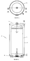
- FIG. 1a, 1b illustrate the basic elements of the heater.
- a heater generally referenced 10, has a cylinder 11 to retain water and in which the water is heated. The weight of the cylinder 11 is primarily borne by the base portion 12.
- a casing 13, typically formed of sheet steel is retained around the rim of the base portion 12 to surround the cylinder 11. Usually, two of the free edges of the sheet steel of the casing 13 are secured together by a vertical weld so that the sheet is in the form of a tube.
- a lid 14 is located in similar fashion on the second edge of the casing 13. Liquid prepolymer is fed into the volume between the cylinder 11 and the casing 13, which prepolymer polymerises into a solid insulating material. As the polymerisation step takes place, the volume of the insulating material increases substantially.
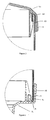
- the engagement of the casing 13 with the base portion 12 is shown in more detail in Figure 3 .
- the base portion 12 is formed of a plastics material such as polypropylene, and has an outer wall 15 and a smaller retaining wall 16 which together form a circular channel 17, passing around the circumference of the base portion 12, into which the casing 13 is inserted.
- a sealant material 18 is added into the channel 17.
- the sealant 18 is for example a polyurethane material which moulds itself around the edge of the casing 13 as the casing 13 is dropped into position.
- the lid 14 - sometimes referred to as a top-moulding - similarly has an outer wall 19 and a retaining wall 20 forming a channel 21 to hold the casing 13.
- An inlet means is provided in the case 13 to allow the polymer precursor to be pumped in. Care needs to be taken that any apertures within the casing 13 are sealed, especially those around any pipes leading to and out of the cylinder 11.
- the heater is assembled as described above in simpler fashion to that in the prior art in that the casing 13 is fitted into the channel 17 of the base portion 12.
- the lid 14 is placed on the free, upper edge of the casing 13.
- axial pressure can be exerted on these components causing the casing 13 to 'bite' into the polypropylene and form a seal with the base portion 12 and the lid 14.
- a clamp can be applied to further enhance the effect and ensure the casing 13 remains in place, pushed into the base portion 12 and lid 14.
- Liquid polyurethane prepolymer is then added into the heater 10, in the space between the cylinder 11 and casing 13.
- a gas carbon dioxide
- the gas collecting together to form bubbles and ensuring that the polymeric material formed is a foam.
- the volume of the polyurethane therefore increases, eventually filling the space with insulating polymer.
- the seal formed by the casing 13 cutting into the polypropylene prevents or hinders the initially liquid prepolymer from running out of the heater 10.
- This facility is enhanced by the presence of the sealant material 18 engaged with the casing 13 to form a further barrier to the escape of the prepolymer.
- the pressure of the expanding foam polymer pushes the base of the casing 13 against the outer wall 15, again forming a yet further seal, preventing the polymer from running out of the heater.
- any polymer which does flow through the additional seals only does so after a longer time than is the case with conventional methods.
- Such material is therefore already partially set and hence more viscous, so that its passage to the outside of the heater is slower.
- the partially set polymer tends to set and self seal before it has a chance to exit the heater and prevents other material from exiting.
- the requirement to include wiper blades as in prior art manufacturing methods, to remove any escaped polymer is therefore obviated.
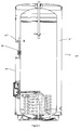
- the heater 40 includes a moulding around a pipe 41 which penetrates through the wall of the cylinder 42.
- Such pipes are sources of heat loss from water within the cylinder 42 and additional insulating mouldings 43 are often placed around the pipes between the cylinder 42 and the outer casing 44.
- the moulding 43 serves an important function of sealing any apertures in the outer casing through which a pipe 41 passes. Moreover, clamping together of the outer casing 44 to the cylinder 42 in the directions shown by arrows D is applied and maintained until the polymeric insulation material has been formed and the moulding 43 assists in enabling position tolerances of the pipe 41 to be met.
- Typical materials from which the moulding 43 is formed is an expanded polystyrene (EPS).
- Figure 4 shows two further mouldings 45, 46.
- the moulding 43 can additionally be used to facilitate fitment and ergonomic placement of control panels and the like.
- a foaming agent can be included to increase the material's volume.
Landscapes
- Engineering & Computer Science (AREA)
- Physics & Mathematics (AREA)
- Thermal Sciences (AREA)
- Chemical & Material Sciences (AREA)
- Combustion & Propulsion (AREA)
- Mechanical Engineering (AREA)
- General Engineering & Computer Science (AREA)
- Thermal Insulation (AREA)
- Lining Or Joining Of Plastics Or The Like (AREA)
- Casting Or Compression Moulding Of Plastics Or The Like (AREA)
Abstract
Description
- The present invention relates to a method of providing an insulating layer around a domestic hot water cylinder. The method is suitable for cylinders housed within an outer casing. Also disclosed is an insulated domestic hot water cylinder.
- In many situations, the installer of a domestic hot water cylinder is supplied with a cylinder already held within a housing: referred to collectively as a heater. The housing, apart from any aesthetic function, is furnished with means to allow the heating element of the heater, located within the cylinder to be controlled and to enable connection of the cylinder to the cold and the hot water inlets and outlets to take place. Typically, the element's controls are mounted onto an outer surface of the heater, although said controls can be located remotely. The present invention is concerned with the provision of a layer of insulating material between the hot-water cylinder and the housing.
- The provision of the insulating layer is well known in the prior art and can be achieved by means of a variety of methods. For example, a layer of preformed insulator such as fibreglass, can be wrapped about the cylinder prior to the installation into the housing. This method is however relatively time consuming and does not always give good contact between the cylinder and the insulator. Moreover, fitment around wires and pipes is not always easy. Additionally, the layer of material is quite heavy which adds to the difficulties in manipulating the heater into position.
- A second method is to secure the cylinder in position within the housing and feed into the space there between a polymer precursor which, when set provides an insulating barrier in close continuous contact with the cylinder. Usually, the polymer precursor includes a foaming agent which both assists the polymer to fill the volume required, but also provides air bubbles within the polymer material which reduce the density of the insulating layer.
- There remain however disadvantages with the second method. The primary disadvantage is that care needs to be taken that the liquid prepolymer does not flow out of the heater before it has a chance to set. Even if only a small proportion leaks out and although the polymers are harmless the polymer can be unsightly and will need to be removed. The precautions usually undertaken to do this, render the method of construction of a heater time consuming in terms of overall time for the process and man hours required to properly manipulate the cylinder. In addition wiper blades usually need to be incorporated to wipe away prepolymer as it leaks out, although even this is not usually completely effective.
- It is therefore an object of the present invention to seek to address the above problems and provide an improved method of manufacture of an insulated hot water cylinder. It is a further object of the invention to provide an improved insulated hot water cylinder.
- According to a first aspect of the invention there is provided a method of manufacture of an insulated hot water container within a housing, said method comprising the steps of:
- a) selecting a base portion to support a hot-water container,
- b) locating the container on the base portion,
- c) providing a sealant in a well between an outer rim wall and a locating wall of the base portion,
- d) locating an outer casing in said well, the outer casing resting on or embedded in the sealant, and surrounding the container,
- e) locating a top moulding on the open end of the outer casing, thereby enclosing the container,
- f) admitting liquid prepolymer into the space between the outer casing and the container and allowing the prepolymer to polymerise to form a solid insulating layer.
- The sealant material in the well helps to prevent the liquid prepolymer from running out onto the base portion at least sufficiently long for the polymer mixture to become more viscous as it polymerises.
- Optionally, the casing is formed of a harder material than that of the base portion or of the top moulding, to enable the casing to press into or cut into the base portion or top moulding and thereby form an additional seal.
- Advantageously, pressure is applied in an axial direction to urge the top moulding, casing and base portion together to reduce the possibility of liquid prepolymer from leaking out.
- Optionally, the method comprises the further step of placing an insulating moulding between the container and the outer casing about a pipe or pipes leading from the container through an aperture in the outer casing and clamping the outer casing to the container such that the aperture is sealed. The moulding assists in meeting manufacturing tolerances for the pipes.
- Preferably, the polymer material formed is a polyurethane which increases in volume during the polymerisation step.
- Advantageously, the expansion of the polymeric material acts to force the casing against the outer rim wall to reduce the possibility of the prepolymer leaking out. Further advantageously, the top moulding includes an outer rim wall, the expanding polymer material acting to urge the casing against the outer rim wall.
- An additional seal is thereby provided which reduces the possibility of leakage.
- According to a second aspect of the invention there is provided a heater, said heater including a hot water container resting upon a base portion, the base portion including an outer rim wall and an inner locating wall;
a casing, formed of sheet material, said casing resting on a sealant material and being retained in position in the channel formed between said outer rim, wall and inner locating wall;
the heater further comprising a top moulding, said top moulding being fixed onto the upper edge of the casing, the casing the base portion and the top moulding co-operating to enclose the container, and insulating material being provided between the container and the casing. - The invention will now be described with reference to the accompanying drawings which show, by way of example only, one example of a hot water heater. In the drawings:
-
Figure 1a is a top view of a heater, -
Figure 1b is a sectional view of the heater through A-A ofFigure 1a ; -
Figure 2 is an exploded view of the region B ofFigure 1b ; -
Figure 3 is an exploded view of region C inFigure 1b ; -
Figure 4 is a sectional view through a heater. - Hot water heaters in which a cylinder, wherein water is heated and stored, is housed within an outer casing or wrapper - typically formed of sheet steel - and having an insulating layer, such as foam, rockwool or other materials having low heat conductance between the cylinder and the casing are well known. The usual prior art method of manufacture of such heaters is however relatively time-consuming and requires several operators to work together co-operatively.
- In summary, a base section is located upside down onto an edge of the sheet material eventually to form the casing. The sheet material, is usually preformed into a tube and tapped into place to ensure that the casing does not fall out. The casing and base section are then turned upside down so that the base section is at the base of the casing. The cylinder is dropped into position, and the lid placed onto the free end of the casing. Again, an operator taps the lid into position. The assembly thus made is then filled with insulating material in the form of a liquid prepolymer. Difficulties are encountered however in that the prepolymer can easily leak out between the casing and the base section. The present invention addresses these problems in one embodiment, by improving the ease of formation and of the strength of the seal between the casing and the base section.
- Referring to the drawings,
Figures 1a, 1b illustrate the basic elements of the heater. A heater, generally referenced 10, has a cylinder 11 to retain water and in which the water is heated. The weight of the cylinder 11 is primarily borne by thebase portion 12. Acasing 13, typically formed of sheet steel is retained around the rim of thebase portion 12 to surround the cylinder 11. Usually, two of the free edges of the sheet steel of thecasing 13 are secured together by a vertical weld so that the sheet is in the form of a tube. Alid 14 is located in similar fashion on the second edge of thecasing 13. Liquid prepolymer is fed into the volume between the cylinder 11 and thecasing 13, which prepolymer polymerises into a solid insulating material. As the polymerisation step takes place, the volume of the insulating material increases substantially. - The engagement of the
casing 13 with thebase portion 12 is shown in more detail inFigure 3 . Thebase portion 12 is formed of a plastics material such as polypropylene, and has anouter wall 15 and asmaller retaining wall 16 which together form acircular channel 17, passing around the circumference of thebase portion 12, into which thecasing 13 is inserted. Prior to said insertion asealant material 18 is added into thechannel 17. Thesealant 18 is for example a polyurethane material which moulds itself around the edge of thecasing 13 as thecasing 13 is dropped into position. - The lid 14 - sometimes referred to as a top-moulding - similarly has an
outer wall 19 and a retainingwall 20 forming achannel 21 to hold thecasing 13. An inlet means is provided in thecase 13 to allow the polymer precursor to be pumped in. Care needs to be taken that any apertures within thecasing 13 are sealed, especially those around any pipes leading to and out of the cylinder 11. - In use, the heater is assembled as described above in simpler fashion to that in the prior art in that the
casing 13 is fitted into thechannel 17 of thebase portion 12. Thelid 14 is placed on the free, upper edge of thecasing 13. As thecasing 13 is of steel and thebase portion 12 andlid 14 of softer polypropylene, axial pressure can be exerted on these components causing thecasing 13 to 'bite' into the polypropylene and form a seal with thebase portion 12 and thelid 14. At this stage a clamp can be applied to further enhance the effect and ensure thecasing 13 remains in place, pushed into thebase portion 12 andlid 14. - Liquid polyurethane prepolymer is then added into the
heater 10, in the space between the cylinder 11 andcasing 13. During the reaction of the polyurethane prepolymer to form polyurethane, a gas (carbon dioxide) is formed, the gas collecting together to form bubbles and ensuring that the polymeric material formed is a foam. The volume of the polyurethane therefore increases, eventually filling the space with insulating polymer. - It is during this polymerisation step that further advantages of the present invention are shown. Firstly, the seal formed by the
casing 13 cutting into the polypropylene prevents or hinders the initially liquid prepolymer from running out of theheater 10. This facility is enhanced by the presence of thesealant material 18 engaged with thecasing 13 to form a further barrier to the escape of the prepolymer. In addition, the pressure of the expanding foam polymer pushes the base of thecasing 13 against theouter wall 15, again forming a yet further seal, preventing the polymer from running out of the heater. - Additionally, any polymer which does flow through the additional seals only does so after a longer time than is the case with conventional methods. Such material is therefore already partially set and hence more viscous, so that its passage to the outside of the heater is slower. The partially set polymer tends to set and self seal before it has a chance to exit the heater and prevents other material from exiting. The requirement to include wiper blades as in prior art manufacturing methods, to remove any escaped polymer is therefore obviated.
- Because of the time taken for foaming to cause the polymer to reach the top of the
heater 10 the polymer is already fairly viscous when it does reach the top. There is usually no requirement for sealant material, similar to that ofmaterial 18 described above to be used between the casing and thelid 14. However such material may be included if so desired. - In
Figure 4 theheater 40 includes a moulding around a pipe 41 which penetrates through the wall of thecylinder 42. Such pipes are sources of heat loss from water within thecylinder 42 and additional insulatingmouldings 43 are often placed around the pipes between thecylinder 42 and theouter casing 44. - The
moulding 43 serves an important function of sealing any apertures in the outer casing through which a pipe 41 passes. Moreover, clamping together of theouter casing 44 to thecylinder 42 in the directions shown by arrows D is applied and maintained until the polymeric insulation material has been formed and themoulding 43 assists in enabling position tolerances of the pipe 41 to be met. Typical materials from which themoulding 43 is formed is an expanded polystyrene (EPS).Figure 4 shows two further mouldings 45, 46. Themoulding 43 can additionally be used to facilitate fitment and ergonomic placement of control panels and the like. - Although the described method is illustrated with a polyurethane insulating material, other polymeric materials known in the art can be used without departing from the scope of the invention. If required, a foaming agent can be included to increase the material's volume.
- It will of course be understood that the invention is not limited to the specific details described herein, which are given by way of example only, and that various modifications and alterations are possible within the scope of the invention.
Claims (8)
- A method of manufacture of an insulated hot water container (11) within a housing (13), said method comprising the steps of:a) selecting a base portion (12) to support a hot-water container (11),b) locating the container on the base portion (12),c) providing a sealant (18) in a well (17) between an outer rim wall (15) and a locating wall (16) of the base portion,d) locating an outer casing in said well (17), the outer casing resting on or embedded in the sealant, and surrounding the container,e) locating a top moulding on the open end of the outer casing, thereby enclosing the container,f) admitting liquid prepolymer into the space between the outer casing and the container and allowing the prepolymer to polymerise to form a solid insulating layer.
- A method according to Claim 1, wherein the casing is formed of a harder material than that of the base portion or of the top moulding.
- A method according to Claim 1 or Claim 2, wherein pressure is applied in an axial direction to urge the top moulding, casing and base portion together.
- A method according to any preceding Claim, wherein the method includes the further steps of placing a moulding between the container and the outer casing about a pipe or pipes leading from the container through an aperture in the outer casing and clamping the outer casing to the container such that the aperture is sealed.
- A method according to any preceding Claim, wherein the liquid prepolymer is selected to be a polyurethane precursor so that the polymer material formed is a polyurethane.
- A method according to any preceding Claim, wherein the expansion of the polymeric material acts to force the casing against the outer rim wall.
- A method according to Claim 6, wherein the top moulding includes an outer rim wall, the expanding polymer material acting to urge the casing against the outer rim wall.
- A heater, said heater including a hot water container resting upon a base portion, the base portion including an outer rim wall and an inner locating wall;
a casing, formed of sheet material, said casing resting on a sealant material and being retained in position in the channel formed between said outer rim, wall and inner locating wall;
the heater further comprising a top moulding, said top moulding being fixed onto the upper edge of the casing, the casing the base portion and the top moulding co-operating to enclose the container, and insulating material being provided between the container and the casing.
Applications Claiming Priority (1)
| Application Number | Priority Date | Filing Date | Title |
|---|---|---|---|
| GBGB1013229.8A GB201013229D0 (en) | 2010-08-05 | 2010-08-05 | An improved method of insulating a hot water cylinder |
Publications (3)
| Publication Number | Publication Date |
|---|---|
| EP2423618A2 true EP2423618A2 (en) | 2012-02-29 |
| EP2423618A3 EP2423618A3 (en) | 2013-01-02 |
| EP2423618B1 EP2423618B1 (en) | 2016-05-04 |
Family
ID=42931277
Family Applications (1)
| Application Number | Title | Priority Date | Filing Date |
|---|---|---|---|
| EP11250707.4A Active EP2423618B1 (en) | 2010-08-05 | 2011-08-05 | An improved method of insulating a hot water cylinder |
Country Status (3)
| Country | Link |
|---|---|
| EP (1) | EP2423618B1 (en) |
| ES (1) | ES2576869T3 (en) |
| GB (1) | GB201013229D0 (en) |
Cited By (1)
| Publication number | Priority date | Publication date | Assignee | Title |
|---|---|---|---|---|
| EP4517210A1 (en) * | 2023-08-28 | 2025-03-05 | Compagnie Industrielle des Chauffe-Eau | Water storage device |
Family Cites Families (7)
| Publication number | Priority date | Publication date | Assignee | Title |
|---|---|---|---|---|
| FR1386696A (en) * | 1964-02-11 | 1965-01-22 | Thomson Houston Comp Francaise | Improvements made to a hot water storage tank and its production technique |
| US4907569A (en) * | 1989-01-05 | 1990-03-13 | A.O. Smith Corporation | Water heater with skirt ring dam |
| US4974551A (en) * | 1989-02-16 | 1990-12-04 | Nelson Thomas E | Water heater and method of fabricating same |
| US5209368A (en) * | 1992-06-09 | 1993-05-11 | Bradenbaugh Kenneth A | Insulated tank construction and improved self positioning sealing device for use therein |
| CA2092348A1 (en) * | 1993-03-24 | 1994-09-25 | Claude Lesage | Insulating support base with elevated circumferential ridge |
| IT1297428B1 (en) * | 1997-12-29 | 1999-12-17 | Merloni Termosanitari Spa | PRESSURE RESISTANT PLASTIC WATER HEATER |
| US6588378B1 (en) * | 2002-08-28 | 2003-07-08 | Rheem Manufacturing Company | Water heater bottom pad/foam dam apparatus with integrated tank support members |
-
2010
- 2010-08-05 GB GBGB1013229.8A patent/GB201013229D0/en not_active Ceased
-
2011
- 2011-08-05 EP EP11250707.4A patent/EP2423618B1/en active Active
- 2011-08-05 ES ES11250707.4T patent/ES2576869T3/en active Active
Non-Patent Citations (1)
| Title |
|---|
| None |
Cited By (2)
| Publication number | Priority date | Publication date | Assignee | Title |
|---|---|---|---|---|
| EP4517210A1 (en) * | 2023-08-28 | 2025-03-05 | Compagnie Industrielle des Chauffe-Eau | Water storage device |
| FR3152576A1 (en) * | 2023-08-28 | 2025-03-07 | Compagnie Industrielle Des Chauffe-Eau | Water storage device |
Also Published As
| Publication number | Publication date |
|---|---|
| EP2423618A3 (en) | 2013-01-02 |
| EP2423618B1 (en) | 2016-05-04 |
| GB201013229D0 (en) | 2010-09-22 |
| ES2576869T3 (en) | 2016-07-11 |
Similar Documents
| Publication | Publication Date | Title |
|---|---|---|
| CA2010115C (en) | Water heater and method of fabricating same | |
| CA2100810C (en) | Water heater foam stop apparatus and associated methods | |
| US20100000614A1 (en) | Plumbing supply boxes | |
| US6267261B1 (en) | Cavitated insulating support base for hot water tank | |
| EP2423618B1 (en) | An improved method of insulating a hot water cylinder | |
| CN103776184A (en) | Storage water heater inner tank | |
| US3258512A (en) | Method of applying a rigid unicellular polyurethane foam coating to pipe fittings | |
| US4861968A (en) | Foam insulated water heater and method of making same | |
| US6143217A (en) | Method of manufacturing a water heater | |
| US4280305A (en) | Roof flashings for use with solar collector | |
| JP3682204B2 (en) | Method of manufacturing a water heater | |
| CN102997425B (en) | Water heater inner container | |
| US20260055929A1 (en) | Centering base for sealing an insulation cavity of a water heating appliance | |
| JP6725987B2 (en) | Through-hole decorative cover mounting structure and air-conditioning system piping installation method | |
| JP2005105712A (en) | Manhole rehabilitation method | |
| JP6524301B2 (en) | Hot water storage tank unit | |
| US20040261728A1 (en) | Water heater chamber wrap | |
| JP2005105711A (en) | Manhole rehabilitation method | |
| KR20100088380A (en) | A method for connecting thermal shrinlcable for sealing | |
| CA2444136A1 (en) | Insulated hot water heater and method of insulating same | |
| CN120700982A (en) | A quick-install bracket-type drainage well | |
| JP6296551B2 (en) | Hot water storage tank unit | |
| EP1608822B1 (en) | Method and arrangement for renovating well, and inner casing element of well | |
| JP6301221B2 (en) | Hot water storage tank unit | |
| CA1151480A (en) | Water heater construction and fabrication method therefore |
Legal Events
| Date | Code | Title | Description |
|---|---|---|---|
| AK | Designated contracting states |
Kind code of ref document: A2 Designated state(s): AL AT BE BG CH CY CZ DE DK EE ES FI FR GB GR HR HU IE IS IT LI LT LU LV MC MK MT NL NO PL PT RO RS SE SI SK SM TR |
|
| AX | Request for extension of the european patent |
Extension state: BA ME |
|
| PUAI | Public reference made under article 153(3) epc to a published international application that has entered the european phase |
Free format text: ORIGINAL CODE: 0009012 |
|
| PUAL | Search report despatched |
Free format text: ORIGINAL CODE: 0009013 |
|
| AK | Designated contracting states |
Kind code of ref document: A3 Designated state(s): AL AT BE BG CH CY CZ DE DK EE ES FI FR GB GR HR HU IE IS IT LI LT LU LV MC MK MT NL NO PL PT RO RS SE SI SK SM TR |
|
| AX | Request for extension of the european patent |
Extension state: BA ME |
|
| RIC1 | Information provided on ipc code assigned before grant |
Ipc: F24H 1/18 20060101AFI20121127BHEP |
|
| 17P | Request for examination filed |
Effective date: 20130701 |
|
| RBV | Designated contracting states (corrected) |
Designated state(s): AL AT BE BG CH CY CZ DE DK EE ES FI FR GB GR HR HU IE IS IT LI LT LU LV MC MK MT NL NO PL PT RO RS SE SI SK SM TR |
|
| 17Q | First examination report despatched |
Effective date: 20150129 |
|
| GRAP | Despatch of communication of intention to grant a patent |
Free format text: ORIGINAL CODE: EPIDOSNIGR1 |
|
| INTG | Intention to grant announced |
Effective date: 20160108 |
|
| GRAS | Grant fee paid |
Free format text: ORIGINAL CODE: EPIDOSNIGR3 |
|
| GRAA | (expected) grant |
Free format text: ORIGINAL CODE: 0009210 |
|
| RAP1 | Party data changed (applicant data changed or rights of an application transferred) |
Owner name: BDR THERMEA GROUP BV |
|
| AK | Designated contracting states |
Kind code of ref document: B1 Designated state(s): AL AT BE BG CH CY CZ DE DK EE ES FI FR GB GR HR HU IE IS IT LI LT LU LV MC MK MT NL NO PL PT RO RS SE SI SK SM TR |
|
| REG | Reference to a national code |
Ref country code: GB Ref legal event code: FG4D |
|
| REG | Reference to a national code |
Ref country code: CH Ref legal event code: EP |
|
| REG | Reference to a national code |
Ref country code: AT Ref legal event code: REF Ref document number: 797272 Country of ref document: AT Kind code of ref document: T Effective date: 20160515 |
|
| REG | Reference to a national code |
Ref country code: IE Ref legal event code: FG4D |
|
| REG | Reference to a national code |
Ref country code: NL Ref legal event code: FP |
|
| REG | Reference to a national code |
Ref country code: DE Ref legal event code: R096 Ref document number: 602011026129 Country of ref document: DE |
|
| REG | Reference to a national code |
Ref country code: ES Ref legal event code: FG2A Ref document number: 2576869 Country of ref document: ES Kind code of ref document: T3 Effective date: 20160711 |
|
| REG | Reference to a national code |
Ref country code: FR Ref legal event code: PLFP Year of fee payment: 6 |
|
| REG | Reference to a national code |
Ref country code: LT Ref legal event code: MG4D |
|
| PG25 | Lapsed in a contracting state [announced via postgrant information from national office to epo] |
Ref country code: NO Free format text: LAPSE BECAUSE OF FAILURE TO SUBMIT A TRANSLATION OF THE DESCRIPTION OR TO PAY THE FEE WITHIN THE PRESCRIBED TIME-LIMIT Effective date: 20160804 Ref country code: LT Free format text: LAPSE BECAUSE OF FAILURE TO SUBMIT A TRANSLATION OF THE DESCRIPTION OR TO PAY THE FEE WITHIN THE PRESCRIBED TIME-LIMIT Effective date: 20160504 Ref country code: FI Free format text: LAPSE BECAUSE OF FAILURE TO SUBMIT A TRANSLATION OF THE DESCRIPTION OR TO PAY THE FEE WITHIN THE PRESCRIBED TIME-LIMIT Effective date: 20160504 |
|
| REG | Reference to a national code |
Ref country code: AT Ref legal event code: MK05 Ref document number: 797272 Country of ref document: AT Kind code of ref document: T Effective date: 20160504 |
|
| PG25 | Lapsed in a contracting state [announced via postgrant information from national office to epo] |
Ref country code: HR Free format text: LAPSE BECAUSE OF FAILURE TO SUBMIT A TRANSLATION OF THE DESCRIPTION OR TO PAY THE FEE WITHIN THE PRESCRIBED TIME-LIMIT Effective date: 20160504 Ref country code: PT Free format text: LAPSE BECAUSE OF FAILURE TO SUBMIT A TRANSLATION OF THE DESCRIPTION OR TO PAY THE FEE WITHIN THE PRESCRIBED TIME-LIMIT Effective date: 20160905 Ref country code: SE Free format text: LAPSE BECAUSE OF FAILURE TO SUBMIT A TRANSLATION OF THE DESCRIPTION OR TO PAY THE FEE WITHIN THE PRESCRIBED TIME-LIMIT Effective date: 20160504 Ref country code: RS Free format text: LAPSE BECAUSE OF FAILURE TO SUBMIT A TRANSLATION OF THE DESCRIPTION OR TO PAY THE FEE WITHIN THE PRESCRIBED TIME-LIMIT Effective date: 20160504 Ref country code: LV Free format text: LAPSE BECAUSE OF FAILURE TO SUBMIT A TRANSLATION OF THE DESCRIPTION OR TO PAY THE FEE WITHIN THE PRESCRIBED TIME-LIMIT Effective date: 20160504 Ref country code: GR Free format text: LAPSE BECAUSE OF FAILURE TO SUBMIT A TRANSLATION OF THE DESCRIPTION OR TO PAY THE FEE WITHIN THE PRESCRIBED TIME-LIMIT Effective date: 20160805 |
|
| PG25 | Lapsed in a contracting state [announced via postgrant information from national office to epo] |
Ref country code: BE Free format text: LAPSE BECAUSE OF NON-PAYMENT OF DUE FEES Effective date: 20160831 |
|
| PG25 | Lapsed in a contracting state [announced via postgrant information from national office to epo] |
Ref country code: EE Free format text: LAPSE BECAUSE OF FAILURE TO SUBMIT A TRANSLATION OF THE DESCRIPTION OR TO PAY THE FEE WITHIN THE PRESCRIBED TIME-LIMIT Effective date: 20160504 Ref country code: DK Free format text: LAPSE BECAUSE OF FAILURE TO SUBMIT A TRANSLATION OF THE DESCRIPTION OR TO PAY THE FEE WITHIN THE PRESCRIBED TIME-LIMIT Effective date: 20160504 Ref country code: RO Free format text: LAPSE BECAUSE OF FAILURE TO SUBMIT A TRANSLATION OF THE DESCRIPTION OR TO PAY THE FEE WITHIN THE PRESCRIBED TIME-LIMIT Effective date: 20160504 Ref country code: SK Free format text: LAPSE BECAUSE OF FAILURE TO SUBMIT A TRANSLATION OF THE DESCRIPTION OR TO PAY THE FEE WITHIN THE PRESCRIBED TIME-LIMIT Effective date: 20160504 Ref country code: CZ Free format text: LAPSE BECAUSE OF FAILURE TO SUBMIT A TRANSLATION OF THE DESCRIPTION OR TO PAY THE FEE WITHIN THE PRESCRIBED TIME-LIMIT Effective date: 20160504 |
|
| REG | Reference to a national code |
Ref country code: DE Ref legal event code: R097 Ref document number: 602011026129 Country of ref document: DE |
|
| PG25 | Lapsed in a contracting state [announced via postgrant information from national office to epo] |
Ref country code: SM Free format text: LAPSE BECAUSE OF FAILURE TO SUBMIT A TRANSLATION OF THE DESCRIPTION OR TO PAY THE FEE WITHIN THE PRESCRIBED TIME-LIMIT Effective date: 20160504 Ref country code: BE Free format text: LAPSE BECAUSE OF FAILURE TO SUBMIT A TRANSLATION OF THE DESCRIPTION OR TO PAY THE FEE WITHIN THE PRESCRIBED TIME-LIMIT Effective date: 20160504 Ref country code: AT Free format text: LAPSE BECAUSE OF FAILURE TO SUBMIT A TRANSLATION OF THE DESCRIPTION OR TO PAY THE FEE WITHIN THE PRESCRIBED TIME-LIMIT Effective date: 20160504 Ref country code: PL Free format text: LAPSE BECAUSE OF FAILURE TO SUBMIT A TRANSLATION OF THE DESCRIPTION OR TO PAY THE FEE WITHIN THE PRESCRIBED TIME-LIMIT Effective date: 20160504 |
|
| PLBE | No opposition filed within time limit |
Free format text: ORIGINAL CODE: 0009261 |
|
| STAA | Information on the status of an ep patent application or granted ep patent |
Free format text: STATUS: NO OPPOSITION FILED WITHIN TIME LIMIT |
|
| PG25 | Lapsed in a contracting state [announced via postgrant information from national office to epo] |
Ref country code: MC Free format text: LAPSE BECAUSE OF FAILURE TO SUBMIT A TRANSLATION OF THE DESCRIPTION OR TO PAY THE FEE WITHIN THE PRESCRIBED TIME-LIMIT Effective date: 20160504 |
|
| REG | Reference to a national code |
Ref country code: CH Ref legal event code: PL |
|
| 26N | No opposition filed |
Effective date: 20170207 |
|
| PG25 | Lapsed in a contracting state [announced via postgrant information from national office to epo] |
Ref country code: LI Free format text: LAPSE BECAUSE OF NON-PAYMENT OF DUE FEES Effective date: 20160831 Ref country code: CH Free format text: LAPSE BECAUSE OF NON-PAYMENT OF DUE FEES Effective date: 20160831 |
|
| PG25 | Lapsed in a contracting state [announced via postgrant information from national office to epo] |
Ref country code: SI Free format text: LAPSE BECAUSE OF FAILURE TO SUBMIT A TRANSLATION OF THE DESCRIPTION OR TO PAY THE FEE WITHIN THE PRESCRIBED TIME-LIMIT Effective date: 20160504 |
|
| REG | Reference to a national code |
Ref country code: FR Ref legal event code: PLFP Year of fee payment: 7 |
|
| PG25 | Lapsed in a contracting state [announced via postgrant information from national office to epo] |
Ref country code: LU Free format text: LAPSE BECAUSE OF NON-PAYMENT OF DUE FEES Effective date: 20160805 |
|
| PG25 | Lapsed in a contracting state [announced via postgrant information from national office to epo] |
Ref country code: CY Free format text: LAPSE BECAUSE OF FAILURE TO SUBMIT A TRANSLATION OF THE DESCRIPTION OR TO PAY THE FEE WITHIN THE PRESCRIBED TIME-LIMIT Effective date: 20160504 Ref country code: HU Free format text: LAPSE BECAUSE OF FAILURE TO SUBMIT A TRANSLATION OF THE DESCRIPTION OR TO PAY THE FEE WITHIN THE PRESCRIBED TIME-LIMIT; INVALID AB INITIO Effective date: 20110805 |
|
| PG25 | Lapsed in a contracting state [announced via postgrant information from national office to epo] |
Ref country code: MK Free format text: LAPSE BECAUSE OF FAILURE TO SUBMIT A TRANSLATION OF THE DESCRIPTION OR TO PAY THE FEE WITHIN THE PRESCRIBED TIME-LIMIT Effective date: 20160504 Ref country code: TR Free format text: LAPSE BECAUSE OF FAILURE TO SUBMIT A TRANSLATION OF THE DESCRIPTION OR TO PAY THE FEE WITHIN THE PRESCRIBED TIME-LIMIT Effective date: 20160504 Ref country code: IS Free format text: LAPSE BECAUSE OF FAILURE TO SUBMIT A TRANSLATION OF THE DESCRIPTION OR TO PAY THE FEE WITHIN THE PRESCRIBED TIME-LIMIT Effective date: 20160504 Ref country code: MT Free format text: LAPSE BECAUSE OF NON-PAYMENT OF DUE FEES Effective date: 20160831 |
|
| PG25 | Lapsed in a contracting state [announced via postgrant information from national office to epo] |
Ref country code: BG Free format text: LAPSE BECAUSE OF FAILURE TO SUBMIT A TRANSLATION OF THE DESCRIPTION OR TO PAY THE FEE WITHIN THE PRESCRIBED TIME-LIMIT Effective date: 20160504 |
|
| REG | Reference to a national code |
Ref country code: FR Ref legal event code: PLFP Year of fee payment: 8 |
|
| PG25 | Lapsed in a contracting state [announced via postgrant information from national office to epo] |
Ref country code: AL Free format text: LAPSE BECAUSE OF FAILURE TO SUBMIT A TRANSLATION OF THE DESCRIPTION OR TO PAY THE FEE WITHIN THE PRESCRIBED TIME-LIMIT Effective date: 20160504 |
|
| PGFP | Annual fee paid to national office [announced via postgrant information from national office to epo] |
Ref country code: IE Payment date: 20210819 Year of fee payment: 11 |
|
| PG25 | Lapsed in a contracting state [announced via postgrant information from national office to epo] |
Ref country code: IE Free format text: LAPSE BECAUSE OF NON-PAYMENT OF DUE FEES Effective date: 20220805 |
|
| PGFP | Annual fee paid to national office [announced via postgrant information from national office to epo] |
Ref country code: NL Payment date: 20230821 Year of fee payment: 13 |
|
| PGFP | Annual fee paid to national office [announced via postgrant information from national office to epo] |
Ref country code: IT Payment date: 20230822 Year of fee payment: 13 |
|
| PGFP | Annual fee paid to national office [announced via postgrant information from national office to epo] |
Ref country code: ES Payment date: 20231027 Year of fee payment: 13 |
|
| REG | Reference to a national code |
Ref country code: NL Ref legal event code: MM Effective date: 20240901 |
|
| PG25 | Lapsed in a contracting state [announced via postgrant information from national office to epo] |
Ref country code: NL Free format text: LAPSE BECAUSE OF NON-PAYMENT OF DUE FEES Effective date: 20240901 |
|
| PG25 | Lapsed in a contracting state [announced via postgrant information from national office to epo] |
Ref country code: IT Free format text: LAPSE BECAUSE OF NON-PAYMENT OF DUE FEES Effective date: 20240805 |
|
| REG | Reference to a national code |
Ref country code: ES Ref legal event code: FD2A Effective date: 20250926 |
|
| PG25 | Lapsed in a contracting state [announced via postgrant information from national office to epo] |
Ref country code: ES Free format text: LAPSE BECAUSE OF NON-PAYMENT OF DUE FEES Effective date: 20240806 |
|
| PGFP | Annual fee paid to national office [announced via postgrant information from national office to epo] |
Ref country code: DE Payment date: 20250820 Year of fee payment: 15 |
|
| PGFP | Annual fee paid to national office [announced via postgrant information from national office to epo] |
Ref country code: GB Payment date: 20250820 Year of fee payment: 15 |
|
| PGFP | Annual fee paid to national office [announced via postgrant information from national office to epo] |
Ref country code: FR Payment date: 20250829 Year of fee payment: 15 |