EP2423609A2 - Heat exchanger and air conditioner on which this heat exchanger is mounted - Google Patents
Heat exchanger and air conditioner on which this heat exchanger is mounted Download PDFInfo
- Publication number
- EP2423609A2 EP2423609A2 EP11177616A EP11177616A EP2423609A2 EP 2423609 A2 EP2423609 A2 EP 2423609A2 EP 11177616 A EP11177616 A EP 11177616A EP 11177616 A EP11177616 A EP 11177616A EP 2423609 A2 EP2423609 A2 EP 2423609A2
- Authority
- EP
- European Patent Office
- Prior art keywords
- pipeline
- aluminum
- heat exchanger
- copper
- refrigerant
- Prior art date
- Legal status (The legal status is an assumption and is not a legal conclusion. Google has not performed a legal analysis and makes no representation as to the accuracy of the status listed.)
- Granted
Links
- 229910052782 aluminium Inorganic materials 0.000 claims abstract description 119
- XAGFODPZIPBFFR-UHFFFAOYSA-N aluminium Chemical compound [Al] XAGFODPZIPBFFR-UHFFFAOYSA-N 0.000 claims abstract description 117
- RYGMFSIKBFXOCR-UHFFFAOYSA-N Copper Chemical compound [Cu] RYGMFSIKBFXOCR-UHFFFAOYSA-N 0.000 claims abstract description 64
- 229910052802 copper Inorganic materials 0.000 claims abstract description 64
- 239000010949 copper Substances 0.000 claims abstract description 64
- 239000007788 liquid Substances 0.000 claims abstract description 55
- 239000003507 refrigerant Substances 0.000 claims abstract description 51
- 229910000838 Al alloy Inorganic materials 0.000 claims abstract description 31
- 229910000881 Cu alloy Inorganic materials 0.000 claims abstract description 12
- 238000009434 installation Methods 0.000 abstract description 9
- 238000005260 corrosion Methods 0.000 description 36
- 230000007797 corrosion Effects 0.000 description 36
- XLYOFNOQVPJJNP-UHFFFAOYSA-N water Substances O XLYOFNOQVPJJNP-UHFFFAOYSA-N 0.000 description 13
- 229910001369 Brass Inorganic materials 0.000 description 7
- 239000010951 brass Substances 0.000 description 7
- 238000005336 cracking Methods 0.000 description 7
- 239000000463 material Substances 0.000 description 6
- 238000005219 brazing Methods 0.000 description 5
- 229910052751 metal Inorganic materials 0.000 description 5
- 239000002184 metal Substances 0.000 description 5
- 150000002739 metals Chemical class 0.000 description 5
- 238000004378 air conditioning Methods 0.000 description 4
- 238000001816 cooling Methods 0.000 description 4
- 238000010438 heat treatment Methods 0.000 description 4
- JPVYNHNXODAKFH-UHFFFAOYSA-N Cu2+ Chemical compound [Cu+2] JPVYNHNXODAKFH-UHFFFAOYSA-N 0.000 description 3
- 238000010586 diagram Methods 0.000 description 3
- 230000005496 eutectics Effects 0.000 description 3
- -1 aluminum ions Chemical class 0.000 description 2
- 239000000470 constituent Substances 0.000 description 2
- 229910001431 copper ion Inorganic materials 0.000 description 2
- 230000005484 gravity Effects 0.000 description 2
- 229910000639 Spring steel Inorganic materials 0.000 description 1
- 230000003247 decreasing effect Effects 0.000 description 1
- 238000007791 dehumidification Methods 0.000 description 1
- 239000000428 dust Substances 0.000 description 1
- 239000006023 eutectic alloy Substances 0.000 description 1
- 238000010348 incorporation Methods 0.000 description 1
- 238000000034 method Methods 0.000 description 1
- 230000002265 prevention Effects 0.000 description 1
- 239000007787 solid Substances 0.000 description 1
- 238000011144 upstream manufacturing Methods 0.000 description 1
Images


Classifications
-
- F—MECHANICAL ENGINEERING; LIGHTING; HEATING; WEAPONS; BLASTING
- F24—HEATING; RANGES; VENTILATING
- F24F—AIR-CONDITIONING; AIR-HUMIDIFICATION; VENTILATION; USE OF AIR CURRENTS FOR SCREENING
- F24F1/00—Room units for air-conditioning, e.g. separate or self-contained units or units receiving primary air from a central station
- F24F1/06—Separate outdoor units, e.g. outdoor unit to be linked to a separate room comprising a compressor and a heat exchanger
- F24F1/26—Refrigerant piping
-
- F—MECHANICAL ENGINEERING; LIGHTING; HEATING; WEAPONS; BLASTING
- F24—HEATING; RANGES; VENTILATING
- F24D—DOMESTIC- OR SPACE-HEATING SYSTEMS, e.g. CENTRAL HEATING SYSTEMS; DOMESTIC HOT-WATER SUPPLY SYSTEMS; ELEMENTS OR COMPONENTS THEREFOR
- F24D15/00—Other domestic- or space-heating systems
- F24D15/04—Other domestic- or space-heating systems using heat pumps
-
- F—MECHANICAL ENGINEERING; LIGHTING; HEATING; WEAPONS; BLASTING
- F24—HEATING; RANGES; VENTILATING
- F24F—AIR-CONDITIONING; AIR-HUMIDIFICATION; VENTILATION; USE OF AIR CURRENTS FOR SCREENING
- F24F1/00—Room units for air-conditioning, e.g. separate or self-contained units or units receiving primary air from a central station
- F24F1/0007—Indoor units, e.g. fan coil units
- F24F1/0043—Indoor units, e.g. fan coil units characterised by mounting arrangements
- F24F1/0057—Indoor units, e.g. fan coil units characterised by mounting arrangements mounted in or on a wall
-
- F—MECHANICAL ENGINEERING; LIGHTING; HEATING; WEAPONS; BLASTING
- F24—HEATING; RANGES; VENTILATING
- F24F—AIR-CONDITIONING; AIR-HUMIDIFICATION; VENTILATION; USE OF AIR CURRENTS FOR SCREENING
- F24F1/00—Room units for air-conditioning, e.g. separate or self-contained units or units receiving primary air from a central station
- F24F1/0007—Indoor units, e.g. fan coil units
- F24F1/0059—Indoor units, e.g. fan coil units characterised by heat exchangers
- F24F1/0063—Indoor units, e.g. fan coil units characterised by heat exchangers by the mounting or arrangement of the heat exchangers
-
- F—MECHANICAL ENGINEERING; LIGHTING; HEATING; WEAPONS; BLASTING
- F24—HEATING; RANGES; VENTILATING
- F24F—AIR-CONDITIONING; AIR-HUMIDIFICATION; VENTILATION; USE OF AIR CURRENTS FOR SCREENING
- F24F1/00—Room units for air-conditioning, e.g. separate or self-contained units or units receiving primary air from a central station
- F24F1/0007—Indoor units, e.g. fan coil units
- F24F1/0059—Indoor units, e.g. fan coil units characterised by heat exchangers
- F24F1/0067—Indoor units, e.g. fan coil units characterised by heat exchangers by the shape of the heat exchangers or of parts thereof, e.g. of their fins
-
- F—MECHANICAL ENGINEERING; LIGHTING; HEATING; WEAPONS; BLASTING
- F24—HEATING; RANGES; VENTILATING
- F24F—AIR-CONDITIONING; AIR-HUMIDIFICATION; VENTILATION; USE OF AIR CURRENTS FOR SCREENING
- F24F1/00—Room units for air-conditioning, e.g. separate or self-contained units or units receiving primary air from a central station
- F24F1/0007—Indoor units, e.g. fan coil units
- F24F1/0068—Indoor units, e.g. fan coil units characterised by the arrangement of refrigerant piping outside the heat exchanger within the unit casing
-
- F—MECHANICAL ENGINEERING; LIGHTING; HEATING; WEAPONS; BLASTING
- F25—REFRIGERATION OR COOLING; COMBINED HEATING AND REFRIGERATION SYSTEMS; HEAT PUMP SYSTEMS; MANUFACTURE OR STORAGE OF ICE; LIQUEFACTION SOLIDIFICATION OF GASES
- F25B—REFRIGERATION MACHINES, PLANTS OR SYSTEMS; COMBINED HEATING AND REFRIGERATION SYSTEMS; HEAT PUMP SYSTEMS
- F25B41/00—Fluid-circulation arrangements
- F25B41/40—Fluid line arrangements
-
- F—MECHANICAL ENGINEERING; LIGHTING; HEATING; WEAPONS; BLASTING
- F28—HEAT EXCHANGE IN GENERAL
- F28D—HEAT-EXCHANGE APPARATUS, NOT PROVIDED FOR IN ANOTHER SUBCLASS, IN WHICH THE HEAT-EXCHANGE MEDIA DO NOT COME INTO DIRECT CONTACT
- F28D1/00—Heat-exchange apparatus having stationary conduit assemblies for one heat-exchange medium only, the media being in contact with different sides of the conduit wall, in which the other heat-exchange medium is a large body of fluid, e.g. domestic or motor car radiators
- F28D1/02—Heat-exchange apparatus having stationary conduit assemblies for one heat-exchange medium only, the media being in contact with different sides of the conduit wall, in which the other heat-exchange medium is a large body of fluid, e.g. domestic or motor car radiators with heat-exchange conduits immersed in the body of fluid
- F28D1/04—Heat-exchange apparatus having stationary conduit assemblies for one heat-exchange medium only, the media being in contact with different sides of the conduit wall, in which the other heat-exchange medium is a large body of fluid, e.g. domestic or motor car radiators with heat-exchange conduits immersed in the body of fluid with tubular conduits
- F28D1/047—Heat-exchange apparatus having stationary conduit assemblies for one heat-exchange medium only, the media being in contact with different sides of the conduit wall, in which the other heat-exchange medium is a large body of fluid, e.g. domestic or motor car radiators with heat-exchange conduits immersed in the body of fluid with tubular conduits the conduits being bent, e.g. in a serpentine or zig-zag
- F28D1/0477—Heat-exchange apparatus having stationary conduit assemblies for one heat-exchange medium only, the media being in contact with different sides of the conduit wall, in which the other heat-exchange medium is a large body of fluid, e.g. domestic or motor car radiators with heat-exchange conduits immersed in the body of fluid with tubular conduits the conduits being bent, e.g. in a serpentine or zig-zag the conduits being bent in a serpentine or zig-zag
- F28D1/0478—Heat-exchange apparatus having stationary conduit assemblies for one heat-exchange medium only, the media being in contact with different sides of the conduit wall, in which the other heat-exchange medium is a large body of fluid, e.g. domestic or motor car radiators with heat-exchange conduits immersed in the body of fluid with tubular conduits the conduits being bent, e.g. in a serpentine or zig-zag the conduits being bent in a serpentine or zig-zag the conduits having a non-circular cross-section
-
- F—MECHANICAL ENGINEERING; LIGHTING; HEATING; WEAPONS; BLASTING
- F28—HEAT EXCHANGE IN GENERAL
- F28F—DETAILS OF HEAT-EXCHANGE AND HEAT-TRANSFER APPARATUS, OF GENERAL APPLICATION
- F28F21/00—Constructions of heat-exchange apparatus characterised by the selection of particular materials
- F28F21/08—Constructions of heat-exchange apparatus characterised by the selection of particular materials of metal
- F28F21/081—Heat exchange elements made from metals or metal alloys
- F28F21/084—Heat exchange elements made from metals or metal alloys from aluminium or aluminium alloys
-
- F—MECHANICAL ENGINEERING; LIGHTING; HEATING; WEAPONS; BLASTING
- F28—HEAT EXCHANGE IN GENERAL
- F28F—DETAILS OF HEAT-EXCHANGE AND HEAT-TRANSFER APPARATUS, OF GENERAL APPLICATION
- F28F21/00—Constructions of heat-exchange apparatus characterised by the selection of particular materials
- F28F21/08—Constructions of heat-exchange apparatus characterised by the selection of particular materials of metal
- F28F21/081—Heat exchange elements made from metals or metal alloys
- F28F21/085—Heat exchange elements made from metals or metal alloys from copper or copper alloys
Definitions
- the present invention relates to a heat exchanger and an air conditioner on which this heat exchanger is mounted and particularly to a heat exchanger in which a heat transfer pipe is formed of aluminum or aluminum alloy and an air conditioner on which this heat exchanger is mounted.
- Heat exchangers in which a heat transfer pipe is made of aluminum or aluminum alloy are known.
- This type of heat exchanger is incorporated in a refrigerating cycle circuit by connecting a refrigerant pipeline formed of copper or copper alloy (hereinafter referred to as a copper pipeline) to a heat transfer pipe formed of aluminum or aluminum alloy (or a refrigerant pipeline formed of aluminum or aluminum alloy connected to this heat transfer pipe.
- a refrigerant pipeline formed of copper or copper alloy hereinafter referred to as a copper pipeline
- a heat transfer pipe formed of aluminum or aluminum alloy or a refrigerant pipeline formed of aluminum or aluminum alloy connected to this heat transfer pipe.
- heat exchangers in which electric corrosion (galvanic corrosion) occurring in the heat transfer pipe or the aluminum pipeline formed of aluminum or aluminum alloy is prevented have been proposed.
- a heat exchanger made of aluminum for example, a heat exchanger "comprising an air conditioner main body and a fixing member 11 that fixes a refrigerating cycle unit including a compressor, a heat exchanger 6 made of aluminum or aluminum alloy, and a refrigerant pipeline 7 made of copper or copper alloy connected to this heat exchanger 6 to the air conditioner main body, by making all of the parts located at an upper position of the heat exchanger 6 of the refrigerant pipeline 7 be composed of a water droplet falling prevention pipeline portion 9 inclined downward toward the refrigerant pipeline 7 from the heat exchanger 6 so that the droplets flow downward through the pipeline and electric corrosion of the heat exchanger 6 by copper ions is prevented" is proposed (See Japanese Unexamined Patent Application Publication No. 6-300303 (Abstract and Fig. 1 ), for example).
- connection pipeline (the above-described aluminum pipeline and copper pipeline) of this heat exchanger made of aluminum is twisted to an arbitrary direction in order to connect the heat exchanger made of aluminum to the refrigerating cycle circuit.
- the present invention was made to solve the above-described problems and an object thereof is to obtain a heat exchanger made of aluminum that can prevent a breakage of a connection pipeline during installation or transfer and an air conditioner on which this heat exchanger is mounted.
- a heat exchanger is a heat exchanger which is provided with a heat transfer pipe formed of aluminum or aluminum alloy and a connection pipeline through which a refrigerant flowing from the heat transfer pipe or the refrigerant flowing into the heat transfer pipe passes and provided in an air conditioner, in which the connection pipeline has a gas pipeline through which a gas refrigerant flows and a liquid pipeline through which a liquid refrigerant or a gas-liquid two-phase refrigerant flows.
- the gas pipeline and the liquid pipeline are constituted by a first refrigerant pipeline formed of aluminum or aluminum alloy and a second refrigerant pipeline formed of copper or copper alloy connected by a connection portion, and the first refrigerant pipeline is connected to the heat transfer pipe so as to form a descending portion which falls from the heat transfer pipe.
- the connection portion is arranged at a straight part of the descending portion, and in the straight part of the descending portion, the first refrigerant pipeline is longer than the second refrigerant pipeline.
- an air conditioner according to the present invention is an air conditioner on which the above-described heat exchanger is mounted.
- connection portion between the first refrigerant pipeline (a refrigerant pipeline formed of aluminum or aluminum alloy) and the second pipeline (a refrigerant pipeline formed of copper or copper alloy) in the connection pipeline is arranged in the straight part of the descending portion.
- the first refrigerant pipeline is longer than the second refrigerant pipeline.
- Fig. 1 is an explanatory diagram illustrating an installed state of an air conditioner according to an embodiment of the present invention.
- the air conditioner according to this embodiment is provided with an indoor unit 100 and an outdoor unit 101.
- the indoor unit 100 is installed on a wall 111 of an air-conditioned space 110.
- the outdoor unit 101 is installed outside the room.
- the indoor unit 100 is provided with a housing 1, a blower 5, an indoor heat exchanger 10 and the like.
- the housing 1 has a substantially rectangular-solid box shape, and, for example, an inlet 2 is formed on an upper part, and an outlet 3 is formed on a lower part.
- a filter 2a that collects dust and the like from indoor air sucked into the housing 1 is disposed.
- an air-direction adjustment mechanism 4 that adjusts the direction of air-conditioning air blown out of the outlet 3 is disposed.
- the blower 5 is a cross-flow fan, for example, and is disposed within the housing 1. Also, the indoor heat exchanger 10 is arranged so as to cover a front face portion, a top face portion, and an upper part of a rear face portion of this blower 5.
- the indoor heat exchanger 10 is a fin-tube-type heat exchanger. Also, in this embodiment, the indoor heat exchanger 10 is constituted by a plurality of heat exchangers 10a, each using a circular-pipe-shaped heat transfer pipe 12, and a plurality of heat exchangers 10b, each using a flat-pipe-shaped heat transfer pipe 16.
- the heat exchangers 10a are provided with a plurality of fins 11, each formed of aluminum or aluminum alloy and the plurality of heat transfer pipes 12 (each having a circular-tube shape), each formed of aluminum or aluminum alloy.
- the fins 11 are layered at predetermined intervals, and the heat transfer pipes 12 (each having a circular-tube shape) are disposed so as to extend through these fins 11.
- the heat exchangers 10b are provided with a plurality of fins 15 formed of aluminum or aluminum alloy and the plurality of the heat transfer pipes 16 (each having a flat-tube shape), each formed of aluminum or aluminum alloy.
- the fins 15 are layered at predetermined intervals, and the heat transfer pipes 16 (each having a flat-tube shape) are disposed so as to extend through these fins 15.
- the indoor heat exchanger 10 is formed such that the heat exchangers 10a using the circular-pipe-shaped heat transfer pipes 12 are arranged on the upstream side of an air path and the heat exchangers 10b using the flat-pipe-shaped heat transfer pipes 16 are arranged on the downstream side of the air path.
- the indoor heat exchanger 10 has a configuration that can be thermally divided into two parts (between the heat exchangers 10a and the heat exchangers 10b, for example), and a decompressing device 8 for re-heating and dehumidifying (an expansion valve, for example) is connected between the heat exchangers thermally divided into two parts.
- a part of the indoor heat exchanger 10 can be made to function as a condenser during a cooling operation, for example, and the remaining part of the indoor heat exchanger 10 can be made to function as an evaporator.
- This indoor heat exchanger 10 is provided with a connection pipeline 20. That is, one of the ends of the connection pipeline 20 is connected to the heat transfer pipe (at least either of the heat transfer pipe 12 and the heat transfer pipe 16) of the indoor heat exchanger 10.
- This connection pipeline 20 is a pipeline formed of copper or copper alloy and is pulled to the outside of the room through a hole portion 112 formed in the wall 111.
- a flare-nut connection portion 29 is disposed on the other end of the connection pipeline 20, .
- the indoor heat exchanger 10 is connected to constituent elements (such as a compressor, an outdoor heat exchanger and the like, not shown) of the refrigerating cycle circuit disposed in the indoor unit 101, thus forming a refrigerating cycle circuit.
- constituent elements such as a compressor, an outdoor heat exchanger and the like, not shown
- connection pipeline 20 is constituted by two pipelines (a gas pipeline 30 and a liquid pipeline 40).
- the flare-nut connection portion 29 is also constituted by two flare-nut connection portions (a flare-nut connection portion 39 of the gas pipeline 30 and a flare-nut connection portion 49 of the liquid pipeline 40).
- the extension pipeline 50 is also constituted by two pipelines, and the flare-nut connection portion 51 of the extension pipeline 50 is also constituted by two flare-nut connection portions.
- connection pipeline 20 Details of the connection pipeline 20 will be described.
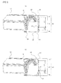
- Figs. 2A and 2B are perspective views illustrating a heat exchanger according to the embodiment of the present invention. Also, Fig. 3 is a front view (enlarged view of an essential part) illustrating this heat exchanger, and Fig. 4 is a side view illustrating this heat exchanger.
- Fig. 2A and Fig. 2B are separate diagrams used to explain the gas pipeline 30 and the liquid pipeline 40 and they are the same except for the reference numerals used. By using Figs. 2A to 4 , details of the connection pipeline 20 according to this embodiment will be described.
- connection pipeline 20 is provided with the gas pipeline 30 and the liquid pipeline 40.
- the gas pipeline corresponds to a first refrigerant pipeline in the present invention
- the liquid pipeline corresponds to a second refrigerant pipeline in the present invention.
- the gas pipeline 30 is a refrigerant pipeline through which mainly a gas refrigerant flows.
- a cooling operation if the indoor heat exchanger 10 functions as an evaporator
- the refrigerant flowing through heat transfer pipes 12 and 16 of the indoor heat exchanger 10 flows out of the indoor unit 100 through the gas pipeline 30.
- a heating operation if the indoor heat exchanger 10 functions as a condenser
- the refrigerant flowing through the heat transfer pipes 12 and 16 of the indoor heat exchanger 10 flows thereinto through the gas pipeline 30.
- the liquid pipeline 40 is a refrigerant pipeline through which mainly a liquid refrigerant flows.
- a cooling operation when the indoor heat exchanger 10 functions as an evaporator, the refrigerant flowing through heat transfer pipes 12 and 16 of the indoor heat exchanger 10 flows thereinto through the liquid pipeline 40.
- a heating operation if the indoor heat exchanger 10 functions as a condenser, the refrigerant having flowed through the heat transfer pipes 12 and 16 of the indoor heat exchanger 10 flows out of the indoor unit 100 through the liquid pipeline 40.
- the refrigerant having flowed through a decompressing device which is a constituent element of the refrigerating cycle circuit, might flow through the liquid pipeline 40.
- the refrigerant flowing through the liquid pipeline 40 is a liquid-rich gas-liquid two-phase refrigerant.
- the gas pipeline 30 is constituted by an aluminum pipeline 31 formed of aluminum or aluminum alloy and a copper pipeline 32 formed of copper or copper alloy.
- the liquid pipeline 40 is constituted by an aluminum pipeline 41 formed of aluminum or aluminum alloy and a copper pipeline 42 formed of copper or copper alloy. That is because of the following reasons.
- the flare-nut connection portions that connect the extension pipeline 50, which has two pipelines, to the gas pipeline 30 and the liquid pipeline 40 have female screw portions disposed on pipelines (the extension pipeline 50, for example) and male screw portions disposed on the other pipelines (the gas pipeline 30 and the liquid pipeline 40, for example), which are connected respectively.
- Each of the female screw portions has a female screw formed on the inner face thereof, and a through hole communicating with a space where this female screw is formed is formed.
- One of the pipelines (the extension pipeline 50, for example) has the diameter of the end portion thereof expanded by flare working and is inserted into this through hole.
- the male screw portion disposed on each of the other pipelines (the gas pipeline 30 and the liquid pipeline 40, for example) is attached to the pipeline end portion by brazing.
- the flare-worked end portion of each of the pipelines (the extension pipeline 50, for example) is sandwiched between the female screw portion and the male screw portion, and the extension pipeline 50, which has two pipelines, is connected to the gas pipeline 30 and the liquid pipeline 40.
- the male screw portion and the female screw portion are formed of brass, considering workability, brazing performances with the copper pipeline and the like.
- the gas pipeline 30 is formed only by the aluminum pipeline 31, and the flare-nut connection portion 39 of the gas pipeline 30 is made to be a male screw portion made of brass, for example, brazing between the aluminum pipeline 31 and the flare-nut connection portion 39 becomes difficult. Also, since the aluminum pipeline 31 and the flare-nut connection portion 39 are metals that are different from each other, electric corrosion (galvanic corrosion) as will be described later might occur at the connection portion between both metals.
- the gas pipeline 30 is formed only by the aluminum pipeline 31 and the flare-nut connection portion 39 of the gas pipeline 30 is made to be a female screw portion made of brass, for example, since the aluminum pipeline 31 and the flare-nut connection portion 39 are metals that are different from each other, electric corrosion (galvanic corrosion) as will be described later might occur at the connection portion between both metals.
- the gas pipeline 30 is formed only by the aluminum pipeline 31, and if the flare-nut connection portion 39 of the gas pipeline 30 is made to be a male screw portion made of aluminum or aluminum alloy, for example, the strength of the thread of the flare-nut connection portion 39 becomes insufficient. Also, at this time, since the flare-nut connection portion 51 of the extension pipeline 50, which is a copper pipeline, is a female screw portion made of brass, electric corrosion (galvanic corrosion) as will be described later might occur between the flare-nut connection portion 39 of the gas pipeline 30 and the flare-nut connection portion 51 of the extension pipeline 50.
- the gas pipeline 30 is formed only by the aluminum pipeline 31, and if the flare-nut connection portion 39 of the gas pipeline 30 is made to be a female screw portion made of aluminum or aluminum alloy, for example, the strength of the thread of the flare-nut connection portion 39 becomes insufficient. Also, when the distal end portion of the aluminum pipeline 31 is to be flare-worked, the occurrence of cracking at the distal end portion of the aluminum pipeline 31 becomes a concern. Also, since the flare-nut connection portion 51 of the extension pipeline 50, which is a copper pipeline, is a male screw portion made of brass, electric corrosion (galvanic corrosion) as will be described later might occur at the connection portion between the flare-nut connection portion 39 of the gas pipeline 30 and the flare-nut connection portion 51 of the extension pipeline 50.
- the gas pipeline 30 is formed only by the aluminum pipeline 31 and the flare-nut connection portion 39 of the gas pipeline 30 and the flare-nut connection portion 51 of the extension pipeline 50 are formed of aluminum or aluminum alloy, for example, the strength of the threads of the flare-nut connection portion 39 and the flare-nut connection portion 51 becomes insufficient. Also, if the flare-nut connection portion 39 of the gas pipeline 30 is made to be a female screw portion, when the distal end portion of the aluminum pipeline 31 is to be flare-worked, the occurrence of cracking at the distal end portion of the aluminum pipeline 31 becomes a concern.
- extension pipeline 50 in order to prevent electric corrosion (galvanic corrosion) as will be described later in the connection portion between the extension pipeline 50 and the flare-nut connection portion 51, it is necessary to form the extension pipeline 50 out of aluminum or aluminum alloy.
- the flare-nut connection portion 51 of the extension pipeline 50 is made to be a female screw portion, when the distal end portion of the extension pipeline 50 is to be flare-worked, the occurrence of cracking at the distal end portion of the extension pipeline 50 becomes a concern.
- the gas pipeline 30 is constituted by the aluminum pipeline 31 and the copper pipeline 32. That is, a flare-nut connection portion 39 made of brass, which is a male screw portion or a female screw portion, is disposed in the distal end portion of the copper pipeline 32 so as to prevent the thread from having insufficient strength or the occurrence of cracking in the pipeline distal end portion during the flare-working, which is a concern.
- the liquid pipeline 40 is constituted by the aluminum pipeline 41 and the copper pipeline 42, and the flare-nut connection portion 49 made of brass, which is a male screw portion or a female screw portion, is disposed in the distal end portion of the copper pipeline 42 so as to prevent the thread from having insufficient strength or the occurrence of cracking in the pipeline distal end portion during the flare-working, which is a concern.
- connection portion 37 between the aluminum pipeline 31 and the copper pipeline 32 is connected by eutectic bonding.
- an end portion on the side opposite the connection portion 37 of the aluminum pipeline 31 is connected to the heat transfer pipe 12 or the heat transfer pipe 16 by brazing, for example.
- a connection portion 47 between the aluminum pipeline 41 and the copper pipeline 42 is connected by eutectic bonding.
- an end portion on the side opposite the connection portion 47 of the aluminum pipeline 41 is connected to the heat transfer pipe 12 or the heat transfer pipe 16 by brazing, for example.
- connection portions 37 and 47 of the aluminum pipelines 31 and 41 and the copper pipelines 32 and 42 are illustrated in Fig. 6 . That is, the distal end portions of the copper pipelines 32 and 42 are inserted into the distal end portions of the aluminum pipelines 31 and 41. Then, the both connection portions are eutectic bonded (bonding by forming eutectic alloy by bringing the metals into contact at a certain temperature). If water adheres to the connection portions 37 and 47, electric corrosion (galvanic corrosion) occurs in the connection portions 37 and 47 (or in more detail, a portion made of aluminum or aluminum alloy) due to the principle, which will be described later. Thus, in order to make the connection portions 37 and 47 waterproof, it is desirable that the connection portions 37 and 47 are covered by a heat shrinkable tube or the connection portions 37 and 47 are painted.
- the gas pipeline 30 and the liquid pipeline 40 are formed in the form as described below.
- a descending portion 33 where the gas pipeline 30 is arranged substantially in the perpendicular direction is formed in the gas pipeline 30.
- the descending portion 33 is formed of an upper curved portion 34, a straight portion 35, and a lower curved portion 36.
- the upper part of the descending portion 33 is the aluminum pipeline 31, and the lower part of the descending portion 33 is the copper pipeline 32.
- the connection portion 37 between the aluminum pipeline 31 and the copper pipeline 32 is arranged in the straight portion 35 of the descending portion 33.
- a descending portion 43 where the liquid pipeline 40 is arranged substantially in the perpendicular direction is formed in the liquid pipeline 40.
- the descending portion 43 is formed of an upper curved portion 44, a straight portion 45, and a lower curved portion 46.
- an upper part of the descending portion 43 is the aluminum pipeline 41
- a lower part of the descending portion 43 is the copper pipeline 42.
- the connection portion 47 between the aluminum pipeline 41 and the copper pipeline 42 is arranged in the straight portion 45 of the descending portion 43.
- the copper pipelines 32 and 42 are arranged in the lower part in the gravity direction than the aluminum pipelines 31 and 41.
- the adhesion of water adhering to the copper pipelines 32 and 42 to the aluminum pipelines 31 and 41 can be prevented, and the occurrence of electric corrosion (galvanic corrosion) in the aluminum pipelines 31 and 41 can be prevented.
- the descending portions 33 and 43 are arranged substantially in the perpendicular direction, but it is needless to say that the descending portions 33 and 43 may be arranged diagonally. That is, it is only necessary that in the descending portions 33 and 43, the copper pipelines 32 and 42 are arranged in the lower part in the gravity direction than the aluminum pipelines 31 and 41.
- the connection portion 37 of the aluminum pipeline 31 with the copper pipeline 32 is arranged above the upper end portion of the spring 60.
- the spring 60 is disposed only on the gas pipeline 30. That is because the gas pipeline 30 is more easily crushed than the liquid pipeline 40 since the pipe diameter of the gas pipeline 30 is larger than that of the liquid pipeline 40.
- the gas pipeline 30 is formed by connecting the aluminum pipeline 31 of ⁇ 9.52 mm ⁇ t1.0 mm and the copper pipeline 32 of ⁇ 9.52 mm ⁇ t0.8 mm.
- the liquid pipeline 40 is formed by connecting the aluminum pipeline 41 of ⁇ 7.00 mm ⁇ t0.75 mm and the copper pipeline 42 of ⁇ 7.00 mm ⁇ t0.60 mm.
- the spring 60 is not disposed on the liquid pipeline 40, but it is desirable that the connection portion 47 of the liquid pipeline 40 (the connection portion between the aluminum pipeline 41 and the copper pipeline 42) is arranged above the upper end portion of the spring 60. This is because the liquid pipeline 40 and the gas pipeline 30 are disposed close to each other in many cases.
- the connection portion 47 of the liquid pipeline 40 above the upper end portion of the spring 60, the spring 60 is no longer brought into contact with the aluminum pipeline 41, and the adhesion of water adhering to the spring 60 to the aluminum pipeline 41 can be prevented, and the occurrence of electric corrosion (galvanic corrosion) in the aluminum pipeline 41 can be prevented.
- the gas pipeline 30 and the liquid pipeline 40 are formed in the shapes described below.
- connection pipeline 20 (the gas pipeline 30 and the liquid pipeline 40) is pulled to the outside through the hole portion 112 in the wall 111.
- the position of the hole portion 112 in the wall 111 and the installation position of the indoor unit 100 are different depending on installation environment.
- the gas pipeline 30 and the liquid pipeline 40 should be able to be twisted in a desired direction within a range of approximately 180° around the descending portions 33 and 43 as illustrated in Fig. 5 (plan view).
- twisting deformation occurs in the descending portions 33 and 43 by a twisting moment applied to them. Because of this twisting deformation, leakage of a refrigerant caused by a breakage or the occurrence of refrigerant pressure loss caused by a pipeline being crushed is a concern in the descending portions 33 and 43.
- a length L1 of the aluminum pipeline 31 is set longer than a length L2 of the copper pipeline 32 as illustrated in Fig. 2A .
- a length L3 of the aluminum pipeline 41 is set longer than a length L4 of the copper pipeline 42.
- the aluminum pipelines 31 and 41 have lower resistance to a twisting moment than the copper pipelines 32 and 42.
- the aluminum pipelines 31 and 41 are more easily deformed than the copper pipelines 32 and 42. Therefore, by setting the ratios of the aluminum pipelines 31 and 41 which are easily deformed to be larger than those of the copper pipelines 32 and 42, a twisting angle per unit length of each of the aluminum pipelines 31 and 41 can be made small.
- the portions of aluminum pipelines 31 and 41 in the straight portions 35 and 45 can flexibly respond to the applied twisting moment. That is, breakage (cracking, crushing or the like) in the portions of the aluminum pipelines 31 and 41 in the strait portions 35 and 45 can be prevented, and the occurrence of leakage of the refrigerant and refrigerant pressure loss can be prevented.
- the copper pipelines 32 and 42 have higher resistance to the twisting moment larger than those of the aluminum pipelines 31 and 41, deformation amounts in the portions of the copper pipelines 32 and 42 in the straight portions 35 and 45 are smaller. Thus, the portions of the copper pipelines 32 and 42 in the straight portions 35 and 45 are hardly broken (cracking, crushing or the like).
- the twisting angle per unit length becomes large.
- the portions of the aluminum pipelines 31 and 41 in the descending portions 33 and 43 leakage of the refrigerant caused by a breakage or the occurrence of refrigerant pressure loss caused by a pipeline being crushed is a concern.
- the relative strength of the aluminum pipelines 31 and 41 can be improved with respect to the copper pipelines 32 and 42, but this method is not preferable. If the thickness of each of the aluminum pipelines 31 and 41 is increased, for example, an increase in the pressure loss in the aluminum pipelines 31 and 41 lowers the refrigerating cycle efficiency or raises the cost of the indoor heat exchanger 10. On the contrary, if the thickness of each of the copper pipelines 32 and 42 is decreased, the withstanding pressure or corrosion margin becomes insufficient.
- the length L1 of the aluminum pipeline 31 is made larger than the length L2 of the copper pipeline 32.
- the length L3 of the aluminum pipeline 41 is set larger than the length L4 of the copper pipeline 42.
- the twisting angle which results in a breakage can be made larger, and a breakage of the connection pipeline 20 (the gas pipeline 30 and the liquid pipeline 40) can be prevented more effectively.
- a material which stretches well from copper or copper alloy for the materials of the copper pipelines 32 and 42 the twisting angle which results in a breakage can be made larger, and a breakage of the connection pipeline 20 (the gas pipeline 30 and the liquid pipeline 40) can be prevented more effectively.
- A3003-0 which stretches well, is used for the materials of the aluminum pipelines 31 and 41.
- C1220-0 which stretches well, is used.
- A3003-0 has stretch of 23% or more in a plate-shaped sample having the thickness of 0.8 to 1.3 mm.
- C1220-0 has stretch of 35% or more in a plate-shaped sample having the thickness of 0.3 to 30 mm.
- the heat exchanger according to the present invention is mounted on the indoor unit 100
- the heat exchanger according to the present invention may be mounted on an outdoor heat exchanger. That is, in this embodiment, the example in which the heat exchanger according to the present invention is used as the indoor heat exchanger 10 has been described, but it is needless to say that the heat exchanger according to the present invention may be used as an outdoor heat exchanger.
- the circular-pipe-shaped heat transfer pipe 12 and the flat-pipe-shaped heat transfer pipe 16 are both used in the indoor heat exchanger 10, but only either of them may be used.
- the present invention has been described using a fin-tube-type heat exchanger (indoor heat exchanger 10) as an example, but it is needless to say that the present invention can be applied to various types of heat exchangers. That is, the present invention can be put into practice by connecting the gas pipeline 30 and the liquid pipeline 40 described in this embodiment to a heat exchanger provided with a heat transfer pipe formed of aluminum or aluminum alloy.
Abstract
Description
- The present invention relates to a heat exchanger and an air conditioner on which this heat exchanger is mounted and particularly to a heat exchanger in which a heat transfer pipe is formed of aluminum or aluminum alloy and an air conditioner on which this heat exchanger is mounted.
- Heat exchangers in which a heat transfer pipe is made of aluminum or aluminum alloy (hereinafter referred to as a heat exchanger made of aluminum) are known. This type of heat exchanger is incorporated in a refrigerating cycle circuit by connecting a refrigerant pipeline formed of copper or copper alloy (hereinafter referred to as a copper pipeline) to a heat transfer pipe formed of aluminum or aluminum alloy (or a refrigerant pipeline formed of aluminum or aluminum alloy connected to this heat transfer pipe. Hereinafter this is referred to as an aluminum pipeline). In the case of incorporation of the heat exchanger made of aluminum in the refrigerating cycle circuit by using the copper pipeline as described above, if water adhering to the copper pipeline adheres to the heat transfer pipe or the aluminum pipeline, there has been a problem that electric corrosion (galvanic corrosion) occurs in the heat transfer pipe or the aluminum pipeline.
- Thus, heat exchangers in which electric corrosion (galvanic corrosion) occurring in the heat transfer pipe or the aluminum pipeline formed of aluminum or aluminum alloy is prevented have been proposed. As this type of a heat exchanger made of aluminum, for example, a heat exchanger "comprising an air conditioner main body and a
fixing member 11 that fixes a refrigerating cycle unit including a compressor, a heat exchanger 6 made of aluminum or aluminum alloy, and arefrigerant pipeline 7 made of copper or copper alloy connected to this heat exchanger 6 to the air conditioner main body, by making all of the parts located at an upper position of the heat exchanger 6 of therefrigerant pipeline 7 be composed of a water droplet falling prevention pipeline portion 9 inclined downward toward therefrigerant pipeline 7 from the heat exchanger 6 so that the droplets flow downward through the pipeline and electric corrosion of the heat exchanger 6 by copper ions is prevented" is proposed (See Japanese Unexamined Patent Application Publication No.6-300303 Fig. 1 ), for example). - When an air conditioner on which a prior-art heat exchanger made of aluminum is mounted (an indoor unit, for example) is installed or transferred, a connection pipeline (the above-described aluminum pipeline and copper pipeline) of this heat exchanger made of aluminum is twisted to an arbitrary direction in order to connect the heat exchanger made of aluminum to the refrigerating cycle circuit. At this time, since no consideration is given to a load applied to the connection pipeline during the installation or transfer in the prior-art heat exchanger made of aluminum, there is a problem that the connection pipeline may be broken during the installation or transfer.
- The present invention was made to solve the above-described problems and an object thereof is to obtain a heat exchanger made of aluminum that can prevent a breakage of a connection pipeline during installation or transfer and an air conditioner on which this heat exchanger is mounted.
- A heat exchanger according to the present invention is a heat exchanger which is provided with a heat transfer pipe formed of aluminum or aluminum alloy and a connection pipeline through which a refrigerant flowing from the heat transfer pipe or the refrigerant flowing into the heat transfer pipe passes and provided in an air conditioner, in which the connection pipeline has a gas pipeline through which a gas refrigerant flows and a liquid pipeline through which a liquid refrigerant or a gas-liquid two-phase refrigerant flows. Also, the gas pipeline and the liquid pipeline are constituted by a first refrigerant pipeline formed of aluminum or aluminum alloy and a second refrigerant pipeline formed of copper or copper alloy connected by a connection portion, and the first refrigerant pipeline is connected to the heat transfer pipe so as to form a descending portion which falls from the heat transfer pipe. The connection portion is arranged at a straight part of the descending portion, and in the straight part of the descending portion, the first refrigerant pipeline is longer than the second refrigerant pipeline.
- Also, an air conditioner according to the present invention is an air conditioner on which the above-described heat exchanger is mounted.
- In the present invention, the connection portion between the first refrigerant pipeline (a refrigerant pipeline formed of aluminum or aluminum alloy) and the second pipeline (a refrigerant pipeline formed of copper or copper alloy) in the connection pipeline is arranged in the straight part of the descending portion. In the straight part of the descending portion, the first refrigerant pipeline is longer than the second refrigerant pipeline. Thus, even if the connection pipeline is twisted and a load is applied to the connection pipeline, a breakage of the connection pipeline can be prevented.
-
-
Fig. 1 is an explanatory diagram illustrating an installed state of an air conditioner according to an embodiment of the present invention. -
Figs. 2 are perspective views illustrating a heat exchanger according to the embodiment of the present invention. -
Fig. 3 is a front view (an enlarged view of an essential part) illustrating the heat exchanger according to the embodiment of the present invention. -
Fig. 4 is a side view illustrating the heat exchanger according to the embodiment of the present invention. -
Fig. 5 is a plan view illustrating an indoor unit according to the embodiment of the present invention. -
Fig. 6 is a sectional view illustrating a connected state between an aluminum pipeline and a copper pipeline according to the embodiment of the present invention. - In an embodiment below, an example in which a heat exchanger according to the present invention is mounted on an indoor unit of an air condition will be described. Also, in the present invention, an example using a wall-hanging type indoor unit will be described.
-
Fig. 1 is an explanatory diagram illustrating an installed state of an air conditioner according to an embodiment of the present invention.
As illustrated inFig. 1 , the air conditioner according to this embodiment is provided with anindoor unit 100 and anoutdoor unit 101. Theindoor unit 100 is installed on awall 111 of an air-conditionedspace 110. Theoutdoor unit 101 is installed outside the room. - The
indoor unit 100 is provided with a housing 1, a blower 5, anindoor heat exchanger 10 and the like. The housing 1 has a substantially rectangular-solid box shape, and, for example, aninlet 2 is formed on an upper part, and an outlet 3 is formed on a lower part. In theinlet 2, afilter 2a that collects dust and the like from indoor air sucked into the housing 1 is disposed. In the outlet 3, an air-direction adjustment mechanism 4 that adjusts the direction of air-conditioning air blown out of the outlet 3 is disposed. - The blower 5 is a cross-flow fan, for example, and is disposed within the housing 1. Also, the
indoor heat exchanger 10 is arranged so as to cover a front face portion, a top face portion, and an upper part of a rear face portion of this blower 5. - The
indoor heat exchanger 10 according to this embodiment is a fin-tube-type heat exchanger. Also, in this embodiment, theindoor heat exchanger 10 is constituted by a plurality ofheat exchangers 10a, each using a circular-pipe-shapedheat transfer pipe 12, and a plurality ofheat exchangers 10b, each using a flat-pipe-shapedheat transfer pipe 16. Theheat exchangers 10a are provided with a plurality offins 11, each formed of aluminum or aluminum alloy and the plurality of heat transfer pipes 12 (each having a circular-tube shape), each formed of aluminum or aluminum alloy. Thefins 11 are layered at predetermined intervals, and the heat transfer pipes 12 (each having a circular-tube shape) are disposed so as to extend through thesefins 11. Theheat exchangers 10b are provided with a plurality offins 15 formed of aluminum or aluminum alloy and the plurality of the heat transfer pipes 16 (each having a flat-tube shape), each formed of aluminum or aluminum alloy. Thefins 15 are layered at predetermined intervals, and the heat transfer pipes 16 (each having a flat-tube shape) are disposed so as to extend through thesefins 15. - When the blower 5 is driven, the indoor air of the air-conditioned
space 110 is sucked into the housing 1 through theinlet 2. This indoor air is heated or cooled while passing through theindoor heat exchanger 10 and becomes air-conditioning air. This air-conditioning air is blown out of the outlet 3. That is, theindoor heat exchanger 10 according to this embodiment is formed such that theheat exchangers 10a using the circular-pipe-shapedheat transfer pipes 12 are arranged on the upstream side of an air path and theheat exchangers 10b using the flat-pipe-shapedheat transfer pipes 16 are arranged on the downstream side of the air path. Theindoor heat exchanger 10 has a configuration that can be thermally divided into two parts (between theheat exchangers 10a and theheat exchangers 10b, for example), and adecompressing device 8 for re-heating and dehumidifying (an expansion valve, for example) is connected between the heat exchangers thermally divided into two parts. As a result, a part of theindoor heat exchanger 10 can be made to function as a condenser during a cooling operation, for example, and the remaining part of theindoor heat exchanger 10 can be made to function as an evaporator. By thermally dividing theindoor heat exchanger 10 into two parts as above, when dehumidification is performed during the cooling operation, the temperature of the air-conditioning air blown out of the outlet 3 is prevented from falling excessively. - This
indoor heat exchanger 10 is provided with aconnection pipeline 20. That is, one of the ends of theconnection pipeline 20 is connected to the heat transfer pipe (at least either of theheat transfer pipe 12 and the heat transfer pipe 16) of theindoor heat exchanger 10. Thisconnection pipeline 20 is a pipeline formed of copper or copper alloy and is pulled to the outside of the room through ahole portion 112 formed in thewall 111. On the other end of theconnection pipeline 20, a flare-nut connection portion 29 is disposed. By connecting a flare-nut connection portion 51 of anextension pipeline 50 connected to theoutdoor unit 101 with the flare-nut connection portion 29, theindoor unit 100 and theoutdoor unit 101 are connected to each other. That is, by connecting the flare-nut connection portion 51 and the flare-nut connection portion 29 to each other, theindoor heat exchanger 10 is connected to constituent elements (such as a compressor, an outdoor heat exchanger and the like, not shown) of the refrigerating cycle circuit disposed in theindoor unit 101, thus forming a refrigerating cycle circuit. - As will be described later, the
connection pipeline 20 is constituted by two pipelines (agas pipeline 30 and a liquid pipeline 40). Thus, the flare-nut connection portion 29 is also constituted by two flare-nut connection portions (a flare-nut connection portion 39 of thegas pipeline 30 and a flare-nut connection portion 49 of the liquid pipeline 40). Therefore, theextension pipeline 50 is also constituted by two pipelines, and the flare-nut connection portion 51 of theextension pipeline 50 is also constituted by two flare-nut connection portions. - Subsequently, details of the
connection pipeline 20 will be described. -
Figs. 2A and 2B are perspective views illustrating a heat exchanger according to the embodiment of the present invention. Also,Fig. 3 is a front view (enlarged view of an essential part) illustrating this heat exchanger, andFig. 4 is a side view illustrating this heat exchanger.Fig. 2A and Fig. 2B are separate diagrams used to explain thegas pipeline 30 and theliquid pipeline 40 and they are the same except for the reference numerals used. By usingFigs. 2A to 4 , details of theconnection pipeline 20 according to this embodiment will be described. - The
connection pipeline 20 is provided with thegas pipeline 30 and theliquid pipeline 40. Here, the gas pipeline corresponds to a first refrigerant pipeline in the present invention, and the liquid pipeline corresponds to a second refrigerant pipeline in the present invention. - The
gas pipeline 30 is a refrigerant pipeline through which mainly a gas refrigerant flows. Thus, in the case of a cooling operation (if theindoor heat exchanger 10 functions as an evaporator), the refrigerant flowing throughheat transfer pipes indoor heat exchanger 10 flows out of theindoor unit 100 through thegas pipeline 30. Also, in the case of a heating operation (if theindoor heat exchanger 10 functions as a condenser), the refrigerant flowing through theheat transfer pipes indoor heat exchanger 10 flows thereinto through thegas pipeline 30. - The
liquid pipeline 40 is a refrigerant pipeline through which mainly a liquid refrigerant flows. Thus, in the case of a cooling operation (when theindoor heat exchanger 10 functions as an evaporator), the refrigerant flowing throughheat transfer pipes indoor heat exchanger 10 flows thereinto through theliquid pipeline 40. Also, in the case of a heating operation (if theindoor heat exchanger 10 functions as a condenser), the refrigerant having flowed through theheat transfer pipes indoor heat exchanger 10 flows out of theindoor unit 100 through theliquid pipeline 40. Depending on the configuration of the refrigerating cycle circuit, the refrigerant having flowed through a decompressing device, which is a constituent element of the refrigerating cycle circuit, might flow through theliquid pipeline 40. In this case, the refrigerant flowing through theliquid pipeline 40 is a liquid-rich gas-liquid two-phase refrigerant. - In this embodiment, the
gas pipeline 30 is constituted by analuminum pipeline 31 formed of aluminum or aluminum alloy and acopper pipeline 32 formed of copper or copper alloy. At the same time, theliquid pipeline 40 is constituted by analuminum pipeline 41 formed of aluminum or aluminum alloy and acopper pipeline 42 formed of copper or copper alloy. That is because of the following reasons. - Usually, the flare-nut connection portions that connect the
extension pipeline 50, which has two pipelines, to thegas pipeline 30 and theliquid pipeline 40 have female screw portions disposed on pipelines (theextension pipeline 50, for example) and male screw portions disposed on the other pipelines (thegas pipeline 30 and theliquid pipeline 40, for example), which are connected respectively. Each of the female screw portions has a female screw formed on the inner face thereof, and a through hole communicating with a space where this female screw is formed is formed. One of the pipelines (theextension pipeline 50, for example) has the diameter of the end portion thereof expanded by flare working and is inserted into this through hole. Also, the male screw portion disposed on each of the other pipelines (thegas pipeline 30 and theliquid pipeline 40, for example) is attached to the pipeline end portion by brazing. By screwing the male screw portion and the female screw portion together, the flare-worked end portion of each of the pipelines (theextension pipeline 50, for example) is sandwiched between the female screw portion and the male screw portion, and theextension pipeline 50, which has two pipelines, is connected to thegas pipeline 30 and theliquid pipeline 40. Usually, the male screw portion and the female screw portion are formed of brass, considering workability, brazing performances with the copper pipeline and the like. - At this time, if the
gas pipeline 30 is formed only by thealuminum pipeline 31, and the flare-nut connection portion 39 of thegas pipeline 30 is made to be a male screw portion made of brass, for example, brazing between thealuminum pipeline 31 and the flare-nut connection portion 39 becomes difficult. Also, since thealuminum pipeline 31 and the flare-nut connection portion 39 are metals that are different from each other, electric corrosion (galvanic corrosion) as will be described later might occur at the connection portion between both metals. Also, if thegas pipeline 30 is formed only by thealuminum pipeline 31 and the flare-nut connection portion 39 of thegas pipeline 30 is made to be a female screw portion made of brass, for example, since thealuminum pipeline 31 and the flare-nut connection portion 39 are metals that are different from each other, electric corrosion (galvanic corrosion) as will be described later might occur at the connection portion between both metals. - Also, if the
gas pipeline 30 is formed only by thealuminum pipeline 31, and if the flare-nut connection portion 39 of thegas pipeline 30 is made to be a male screw portion made of aluminum or aluminum alloy, for example, the strength of the thread of the flare-nut connection portion 39 becomes insufficient. Also, at this time, since the flare-nut connection portion 51 of theextension pipeline 50, which is a copper pipeline, is a female screw portion made of brass, electric corrosion (galvanic corrosion) as will be described later might occur between the flare-nut connection portion 39 of thegas pipeline 30 and the flare-nut connection portion 51 of theextension pipeline 50. - Also, if the
gas pipeline 30 is formed only by thealuminum pipeline 31, and if the flare-nut connection portion 39 of thegas pipeline 30 is made to be a female screw portion made of aluminum or aluminum alloy, for example, the strength of the thread of the flare-nut connection portion 39 becomes insufficient. Also, when the distal end portion of thealuminum pipeline 31 is to be flare-worked, the occurrence of cracking at the distal end portion of thealuminum pipeline 31 becomes a concern. Also, since the flare-nut connection portion 51 of theextension pipeline 50, which is a copper pipeline, is a male screw portion made of brass, electric corrosion (galvanic corrosion) as will be described later might occur at the connection portion between the flare-nut connection portion 39 of thegas pipeline 30 and the flare-nut connection portion 51 of theextension pipeline 50. - Also, if the
gas pipeline 30 is formed only by thealuminum pipeline 31 and the flare-nut connection portion 39 of thegas pipeline 30 and the flare-nut connection portion 51 of theextension pipeline 50 are formed of aluminum or aluminum alloy, for example, the strength of the threads of the flare-nut connection portion 39 and the flare-nut connection portion 51 becomes insufficient. Also, if the flare-nut connection portion 39 of thegas pipeline 30 is made to be a female screw portion, when the distal end portion of thealuminum pipeline 31 is to be flare-worked, the occurrence of cracking at the distal end portion of thealuminum pipeline 31 becomes a concern. Also, in order to prevent electric corrosion (galvanic corrosion) as will be described later in the connection portion between theextension pipeline 50 and the flare-nut connection portion 51, it is necessary to form theextension pipeline 50 out of aluminum or aluminum alloy. Thus, if the flare-nut connection portion 51 of theextension pipeline 50 is made to be a female screw portion, when the distal end portion of theextension pipeline 50 is to be flare-worked, the occurrence of cracking at the distal end portion of theextension pipeline 50 becomes a concern. - Then, in this embodiment, the
gas pipeline 30 is constituted by thealuminum pipeline 31 and thecopper pipeline 32. That is, a flare-nut connection portion 39 made of brass, which is a male screw portion or a female screw portion, is disposed in the distal end portion of thecopper pipeline 32 so as to prevent the thread from having insufficient strength or the occurrence of cracking in the pipeline distal end portion during the flare-working, which is a concern. Similarly, theliquid pipeline 40 is constituted by thealuminum pipeline 41 and thecopper pipeline 42, and the flare-nut connection portion 49 made of brass, which is a male screw portion or a female screw portion, is disposed in the distal end portion of thecopper pipeline 42 so as to prevent the thread from having insufficient strength or the occurrence of cracking in the pipeline distal end portion during the flare-working, which is a concern. - Here, in this embodiment, a
connection portion 37 between thealuminum pipeline 31 and thecopper pipeline 32 is connected by eutectic bonding. Also, an end portion on the side opposite theconnection portion 37 of thealuminum pipeline 31 is connected to theheat transfer pipe 12 or theheat transfer pipe 16 by brazing, for example. Similarly, aconnection portion 47 between thealuminum pipeline 41 and thecopper pipeline 42 is connected by eutectic bonding. Also, an end portion on the side opposite theconnection portion 47 of thealuminum pipeline 41 is connected to theheat transfer pipe 12 or theheat transfer pipe 16 by brazing, for example. - In more detail, the
connection portions aluminum pipelines copper pipelines Fig. 6 . That is, the distal end portions of thecopper pipelines aluminum pipelines connection portions connection portions 37 and 47 (or in more detail, a portion made of aluminum or aluminum alloy) due to the principle, which will be described later. Thus, in order to make theconnection portions connection portions connection portions - Also, in this embodiment, in order to prevent the occurrence of electric corrosion (galvanic corrosion) in the
aluminum pipelines gas pipeline 30 and theliquid pipeline 40 are formed in the form as described below. - If water containing copper ions (Cu2+) splashes over aluminum or aluminum alloy, aluminum or aluminum alloy becomes:
2Al + 3Cu2+ -> 2Al3+ + 3Cu
due to a difference in ionization tendency. That is, aluminum is ionized, and electric corrosion (galvanic corrosion) occurs in aluminum or aluminum alloy. - On the other hand, even when water droplets containing aluminum ions (Al3+) adhere to aluminum or aluminum alloy, since they are the same atoms, electric corrosion (galvanic corrosion) does not occur in aluminum or aluminum alloy. Even when water droplets containing aluminum ions (Al3+) adhere to copper or copper alloy, since copper has an ionization tendency smaller than that of aluminum, electric corrosion (galvanic corrosion) does not occur in copper or copper alloy.
- Thus, in this embodiment, a descending
portion 33 where thegas pipeline 30 is arranged substantially in the perpendicular direction is formed in thegas pipeline 30. The descendingportion 33 is formed of an uppercurved portion 34, astraight portion 35, and a lowercurved portion 36. Also, the upper part of the descendingportion 33 is thealuminum pipeline 31, and the lower part of the descendingportion 33 is thecopper pipeline 32. Theconnection portion 37 between thealuminum pipeline 31 and thecopper pipeline 32 is arranged in thestraight portion 35 of the descendingportion 33. - Similarly, a descending
portion 43 where theliquid pipeline 40 is arranged substantially in the perpendicular direction is formed in theliquid pipeline 40. The descendingportion 43 is formed of an uppercurved portion 44, astraight portion 45, and a lowercurved portion 46. Also, an upper part of the descendingportion 43 is thealuminum pipeline 41, and a lower part of the descendingportion 43 is thecopper pipeline 42. Theconnection portion 47 between thealuminum pipeline 41 and thecopper pipeline 42 is arranged in thestraight portion 45 of the descendingportion 43. - As described above, by forming the descending
portions gas pipeline 30 and theliquid pipeline 40, and by arranging theconnection portions straight portions portions copper pipelines aluminum pipelines copper pipelines aluminum pipelines aluminum pipelines - In this embodiment, the descending
portions portions portions copper pipelines aluminum pipelines - Also, in this embodiment, when the
gas pipeline 30 is bent at installation or transfer of theindoor unit 100, in order to prevent thegas pipeline 30 from being crushed, aspring 60 made of spring steel, for example, covers the descendingportion 33 from the lowercurved portion 36 to thestraight portion 35. Thus, theconnection portion 37 of thealuminum pipeline 31 with thecopper pipeline 32 is arranged above the upper end portion of thespring 60. As a result, since thespring 60 is not brought into contact with thealuminum pipeline 31, water adhering to thespring 60 is prevented from adhering to thealuminum pipeline 31, and the occurrence of electric corrosion (galvanic corrosion) in thealuminum pipeline 31 can be also prevented. Also, even if water adhering to thecopper pipeline 32 rises through thespring 60, the adhesion of this water to thealuminum pipeline 31 can be prevented, and the occurrence of electric corrosion (galvanic corrosion) in thealuminum pipeline 31 can be prevented. - In this embodiment, the
spring 60 is disposed only on thegas pipeline 30. That is because thegas pipeline 30 is more easily crushed than theliquid pipeline 40 since the pipe diameter of thegas pipeline 30 is larger than that of theliquid pipeline 40. In this embodiment, thegas pipeline 30 is formed by connecting thealuminum pipeline 31 of φ9.52 mm × t1.0 mm and thecopper pipeline 32 of φ9.52 mm × t0.8 mm. Also, theliquid pipeline 40 is formed by connecting thealuminum pipeline 41 of φ7.00 mm × t0.75 mm and thecopper pipeline 42 of φ7.00 mm × t0.60 mm. - Also, in this embodiment, the
spring 60 is not disposed on theliquid pipeline 40, but it is desirable that theconnection portion 47 of the liquid pipeline 40 (the connection portion between thealuminum pipeline 41 and the copper pipeline 42) is arranged above the upper end portion of thespring 60. This is because theliquid pipeline 40 and thegas pipeline 30 are disposed close to each other in many cases. By arranging theconnection portion 47 of theliquid pipeline 40 above the upper end portion of thespring 60, thespring 60 is no longer brought into contact with thealuminum pipeline 41, and the adhesion of water adhering to thespring 60 to thealuminum pipeline 41 can be prevented, and the occurrence of electric corrosion (galvanic corrosion) in thealuminum pipeline 41 can be prevented. Also, even if water adhering to thecopper pipeline 32 of thegas pipeline 30 rises through thespring 60, the adhesion of this water to thealuminum pipeline 41 of theliquid pipeline 40 can be prevented, and the occurrence of electric corrosion (galvanic corrosion) in thealuminum pipeline 41 can be prevented. - Also, in this embodiment, in order to prevent breakage of the
gas pipeline 30 and theliquid pipeline 40 during installation or transfer of theindoor unit 100, thegas pipeline 30 and theliquid pipeline 40 are formed in the shapes described below. - As illustrated in
Fig. 1 , when theindoor unit 100 is installed, the connection pipeline 20 (thegas pipeline 30 and the liquid pipeline 40) is pulled to the outside through thehole portion 112 in thewall 111. At this time, the position of thehole portion 112 in thewall 111 and the installation position of theindoor unit 100 are different depending on installation environment. Thus, thegas pipeline 30 and theliquid pipeline 40 should be able to be twisted in a desired direction within a range of approximately 180° around the descendingportions Fig. 5 (plan view). - If the
gas pipeline 30 and theliquid pipeline 40 are twisted around the descendingportions portions portions - Thus, in this embodiment, in the
straight portion 35 of the descendingportion 33 of thegas pipeline 30, a length L1 of thealuminum pipeline 31 is set longer than a length L2 of thecopper pipeline 32 as illustrated inFig. 2A . Also, as illustrated inFig. 2B , in thestraight portion 45 in the descendingportion 43 of theliquid pipeline 40, a length L3 of thealuminum pipeline 41 is set longer than a length L4 of thecopper pipeline 42. As a result, a breakage of thegas pipeline 30 and theliquid pipeline 40 during installation or transfer of theindoor unit 100 is prevented. - In more detail, the
aluminum pipelines copper pipelines straight portions aluminum pipelines copper pipelines aluminum pipelines copper pipelines aluminum pipelines aluminum pipelines straight portions aluminum pipelines strait portions - On the other hand, since the
copper pipelines aluminum pipelines copper pipelines straight portions copper pipelines straight portions - In the
straight portions aluminum pipelines copper pipelines aluminum pipelines copper pipelines aluminum pipelines portions - Also, in order to reduce the twisting angle per unit length of the
aluminum pipelines aluminum pipelines copper pipelines aluminum pipelines aluminum pipelines indoor heat exchanger 10. On the contrary, if the thickness of each of thecopper pipelines - As described above, in the
indoor heat exchanger 10 according to this embodiment, in thestraight portion 35 of the descendingportion 33 of thegas pipeline 30, the length L1 of thealuminum pipeline 31 is made larger than the length L2 of thecopper pipeline 32. Also, in thestraight portion 45 in the descendingportion 43 of theliquid pipeline 40, the length L3 of thealuminum pipeline 41 is set larger than the length L4 of thecopper pipeline 42. Thus, in the descendingportions aluminum pipelines indoor unit 100 is to be installed or transferred, a breakage of the connection pipeline 20 (thegas pipeline 30 and the liquid pipeline 40) can be prevented. - Here, by selecting a material which grows well from aluminum or aluminum alloy for the materials of the
aluminum pipelines gas pipeline 30 and the liquid pipeline 40) can be prevented more effectively. Similarly, by selecting a material which stretches well from copper or copper alloy for the materials of thecopper pipelines gas pipeline 30 and the liquid pipeline 40) can be prevented more effectively. In this embodiment, for the materials of thealuminum pipelines copper pipelines - In this embodiment, an example in which the heat exchanger according to the present invention is mounted on the
indoor unit 100 has been described, but it is needless to say that the heat exchanger according to the present invention may be mounted on an outdoor heat exchanger. That is, in this embodiment, the example in which the heat exchanger according to the present invention is used as theindoor heat exchanger 10 has been described, but it is needless to say that the heat exchanger according to the present invention may be used as an outdoor heat exchanger. - Also, in this embodiment, the circular-pipe-shaped
heat transfer pipe 12 and the flat-pipe-shapedheat transfer pipe 16 are both used in theindoor heat exchanger 10, but only either of them may be used. Also, in this embodiment, the present invention has been described using a fin-tube-type heat exchanger (indoor heat exchanger 10) as an example, but it is needless to say that the present invention can be applied to various types of heat exchangers. That is, the present invention can be put into practice by connecting thegas pipeline 30 and theliquid pipeline 40 described in this embodiment to a heat exchanger provided with a heat transfer pipe formed of aluminum or aluminum alloy. -
- 1 housing, 2 inlet, 2a filter, 3 outlet, 4 air-direction adjustment mechanism, 5 blower, 8 decompressing device for re-heating and dehumidifying, 10 indoor heat exchanger, 10a heat exchanger, 10b heat exchanger, 11 fin, 12 heat transfer pipe (circular-pipe-shaped), 15 fin, 16 heat transfer pipe (flat-pipe), 20 connection pipeline, 29 flare-nut connection portion, 30 gas pipeline, 31 aluminum pipeline, 32 copper pipeline, 33 descending portion, 34 upper curved portion, 35 straight portion, 36 lower curved portion, 37 connection portion, 39 flare-nut connection portion, 40 liquid pipeline, 41 aluminum pipeline, 42 copper pipeline, 43 descending portion, 44 upper curved portion, 45 straight portion, 46 lower curved portion, 47 connection portion, 49 flare-nut connection portion, 50 extension pipeline, 51 flare-nut connection portion, 60 spring, 100 indoor unit, 101 outdoor unit, 110 air-conditioned space, 111 wall, 112 hole portion.
Claims (3)
- A heat exchanger (10) comprising:a heat transfer pipe (12) formed of aluminum or aluminum alloy; anda connection pipeline (20) through which a refrigerant flowing in from said heat transfer pipe (12) or a refrigerant flowing into said heat transfer pipe (12) passes, and mounted in an air conditioner, wherein:said connection pipeline (20) has a gas pipeline (30) through which a gas refrigerant flows and a liquid pipeline (40) through which a liquid refrigerant or a gas-liquid two-phase refrigerant flows;each of said gas pipeline (30) and said liquid pipeline (40) is constituted by connecting a first refrigerant pipeline (31, 41) formed of aluminum or aluminum alloy and a second refrigerant pipeline (32, 42) formed of copper and copper alloy using a connection portion (37, 47);the first refrigerant pipeline (31, 41) is connected to said heat transfer pipe (12) to form a descending portion (33, 43) descending from said heat transfer pipe (12);said connection portion (37, 47) is arranged in a straight part of said descending portion (33, 43); andin the straight part of said descending portion (33, 43), said first refrigerant pipeline (31, 41) is longer than said second refrigerant pipeline (32, 42).
- The heat exchanger (10) of Claim 1,
whereina spring (60) that suppresses deformation of said gas pipeline (30) covers on a lower part of said descending portion (33, 43) of said gas pipeline (30); andin a state when an air conditioner having the heat exchanger (10) is installed, said connection portion (37, 47) is arranged above an upper end portion of said spring (60). - The heat exchanger (10) of Claim 2,
whereinin the state when the air conditioner having the heat exchanger (10) is installed, said connection portion (37, 47) of said liquid pipeline (40) is arranged above the upper end portion of said spring (60) that covers said gas pipeline (30).4. An air conditioner comprising the heat exchanger (10) according to any one of Claims 1 to 3.
Applications Claiming Priority (1)
| Application Number | Priority Date | Filing Date | Title |
|---|---|---|---|
| JP2010185948A JP5388969B2 (en) | 2010-08-23 | 2010-08-23 | Heat exchanger and air conditioner equipped with this heat exchanger |
Publications (3)
| Publication Number | Publication Date |
|---|---|
| EP2423609A2 true EP2423609A2 (en) | 2012-02-29 |
| EP2423609A3 EP2423609A3 (en) | 2016-11-09 |
| EP2423609B1 EP2423609B1 (en) | 2020-04-15 |
Family
ID=44658635
Family Applications (1)
| Application Number | Title | Priority Date | Filing Date |
|---|---|---|---|
| EP11177616.7A Active EP2423609B1 (en) | 2010-08-23 | 2011-08-16 | Heat exchanger and air conditioner on which this heat exchanger is mounted |
Country Status (3)
| Country | Link |
|---|---|
| EP (1) | EP2423609B1 (en) |
| JP (1) | JP5388969B2 (en) |
| CN (1) | CN102374592B (en) |
Cited By (16)
| Publication number | Priority date | Publication date | Assignee | Title |
|---|---|---|---|---|
| CN105539803A (en) * | 2015-12-14 | 2016-05-04 | 浙江海洋学院 | Frostless air conditioner refrigeration device for ship by virtue of afterheat reproduction |
| EP3101353A1 (en) * | 2014-01-30 | 2016-12-07 | Daikin Industries, Ltd. | Air conditioner indoor unit |
| WO2017136172A1 (en) * | 2016-02-03 | 2017-08-10 | Carrier Corporation | Refrigeration display cabinet system |
| WO2019174200A1 (en) * | 2018-03-15 | 2019-09-19 | 格力电器(武汉)有限公司 | Indoor unit and air conditioner having same |
| US11365335B2 (en) | 2017-12-18 | 2022-06-21 | Daikin Industries, Ltd. | Composition comprising refrigerant, use thereof, refrigerating machine having same, and method for operating said refrigerating machine |
| US11435118B2 (en) | 2017-12-18 | 2022-09-06 | Daikin Industries, Ltd. | Heat source unit and refrigeration cycle apparatus |
| US11441802B2 (en) | 2017-12-18 | 2022-09-13 | Daikin Industries, Ltd. | Air conditioning apparatus |
| US11441819B2 (en) | 2017-12-18 | 2022-09-13 | Daikin Industries, Ltd. | Refrigeration cycle apparatus |
| US11493244B2 (en) | 2017-12-18 | 2022-11-08 | Daikin Industries, Ltd. | Air-conditioning unit |
| US11492527B2 (en) | 2017-12-18 | 2022-11-08 | Daikin Industries, Ltd. | Composition containing refrigerant, use of said composition, refrigerator having said composition, and method for operating said refrigerator |
| US11506425B2 (en) | 2017-12-18 | 2022-11-22 | Daikin Industries, Ltd. | Refrigeration cycle apparatus |
| US11535781B2 (en) | 2017-12-18 | 2022-12-27 | Daikin Industries, Ltd. | Refrigeration cycle apparatus |
| US11549695B2 (en) | 2017-12-18 | 2023-01-10 | Daikin Industries, Ltd. | Heat exchange unit |
| US11549041B2 (en) | 2017-12-18 | 2023-01-10 | Daikin Industries, Ltd. | Composition containing refrigerant, use of said composition, refrigerator having said composition, and method for operating said refrigerator |
| US11820933B2 (en) | 2017-12-18 | 2023-11-21 | Daikin Industries, Ltd. | Refrigeration cycle apparatus |
| US11906207B2 (en) | 2017-12-18 | 2024-02-20 | Daikin Industries, Ltd. | Refrigeration apparatus |
Families Citing this family (7)
| Publication number | Priority date | Publication date | Assignee | Title |
|---|---|---|---|---|
| JP6079619B2 (en) * | 2013-12-27 | 2017-02-15 | ダイキン工業株式会社 | Air conditioning indoor unit |
| JP6107724B2 (en) * | 2014-03-26 | 2017-04-05 | 株式会社富士通ゼネラル | Piping connection structure |
| JP2017172885A (en) * | 2016-03-24 | 2017-09-28 | 株式会社富士通ゼネラル | Auxiliary connection pipe and air conditioner |
| JP2019007642A (en) * | 2017-06-21 | 2019-01-17 | 日立ジョンソンコントロールズ空調株式会社 | Refrigeration device |
| WO2019123897A1 (en) * | 2017-12-18 | 2019-06-27 | ダイキン工業株式会社 | Refrigeration cycle device |
| JP6865809B2 (en) * | 2019-12-24 | 2021-04-28 | 三菱電機株式会社 | Air conditioner |
| JP7133076B1 (en) | 2021-09-30 | 2022-09-07 | ダイキン工業株式会社 | Heat exchange units and air conditioners |
Citations (1)
| Publication number | Priority date | Publication date | Assignee | Title |
|---|---|---|---|---|
| JPH06300303A (en) | 1993-04-15 | 1994-10-28 | Sanyo Electric Co Ltd | Air conditioner |
Family Cites Families (17)
| Publication number | Priority date | Publication date | Assignee | Title |
|---|---|---|---|---|
| US4186474A (en) * | 1976-06-07 | 1980-02-05 | Westinghouse Electric Corp. | Method of making heat exchanger coil |
| JPH05164349A (en) * | 1991-12-13 | 1993-06-29 | Mitsubishi Electric Corp | Air conditioner |
| JPH072768U (en) * | 1993-05-31 | 1995-01-17 | 清 藤原 | Method of protecting thermoplastic resin from heat transfer tube external pressure |
| JP3223722B2 (en) * | 1994-09-16 | 2001-10-29 | 株式会社日立製作所 | Air conditioner |
| JPH0914781A (en) * | 1995-06-30 | 1997-01-17 | Mitsubishi Heavy Ind Ltd | Cooling-heating split type air conditioner |
| JPH10122586A (en) * | 1996-10-18 | 1998-05-15 | Fujitsu General Ltd | Air conditioner |
| JPH11118202A (en) * | 1997-08-13 | 1999-04-30 | Toshiba Corp | Split air conditioner |
| JP3899173B2 (en) * | 1997-12-17 | 2007-03-28 | 昭和電工株式会社 | Heat exchanger |
| JP3985555B2 (en) * | 2002-03-18 | 2007-10-03 | ダイキン工業株式会社 | Connection structure of refrigerant piping of air conditioner |
| KR100503486B1 (en) * | 2002-03-28 | 2005-07-25 | 장인환 | Refrigerant pipe connecting structure of a refrigerator and connecting method thereof |
| JP2005055081A (en) * | 2003-08-05 | 2005-03-03 | Matsushita Electric Ind Co Ltd | Heat exchanger and vending machine provided with the heat exchanger |
| JP2005090761A (en) * | 2003-09-12 | 2005-04-07 | Matsushita Electric Ind Co Ltd | Air conditioner |
| KR100762268B1 (en) * | 2006-07-24 | 2007-10-01 | 삼성전자주식회사 | Water cooling type air conditioner |
| US8152047B2 (en) * | 2007-04-16 | 2012-04-10 | Luvata Franklin, Inc. | Method of producing a corrosion resistant aluminum heat exchanger |
| KR20080095628A (en) * | 2007-04-25 | 2008-10-29 | 엘지전자 주식회사 | Air conditioner |
| JP2009092274A (en) * | 2007-10-05 | 2009-04-30 | Hitachi Appliances Inc | Air conditioner |
| JP2010112667A (en) * | 2008-11-10 | 2010-05-20 | Mitsubishi Electric Corp | Air conditioner |
-
2010
- 2010-08-23 JP JP2010185948A patent/JP5388969B2/en active Active
-
2011
- 2011-08-16 EP EP11177616.7A patent/EP2423609B1/en active Active
- 2011-08-23 CN CN201110241862.XA patent/CN102374592B/en active Active
Patent Citations (1)
| Publication number | Priority date | Publication date | Assignee | Title |
|---|---|---|---|---|
| JPH06300303A (en) | 1993-04-15 | 1994-10-28 | Sanyo Electric Co Ltd | Air conditioner |
Cited By (17)
| Publication number | Priority date | Publication date | Assignee | Title |
|---|---|---|---|---|
| EP3101353A1 (en) * | 2014-01-30 | 2016-12-07 | Daikin Industries, Ltd. | Air conditioner indoor unit |
| EP3101353A4 (en) * | 2014-01-30 | 2017-05-17 | Daikin Industries, Ltd. | Air conditioner indoor unit |
| CN105539803A (en) * | 2015-12-14 | 2016-05-04 | 浙江海洋学院 | Frostless air conditioner refrigeration device for ship by virtue of afterheat reproduction |
| WO2017136172A1 (en) * | 2016-02-03 | 2017-08-10 | Carrier Corporation | Refrigeration display cabinet system |
| US11535781B2 (en) | 2017-12-18 | 2022-12-27 | Daikin Industries, Ltd. | Refrigeration cycle apparatus |
| US11365335B2 (en) | 2017-12-18 | 2022-06-21 | Daikin Industries, Ltd. | Composition comprising refrigerant, use thereof, refrigerating machine having same, and method for operating said refrigerating machine |
| US11435118B2 (en) | 2017-12-18 | 2022-09-06 | Daikin Industries, Ltd. | Heat source unit and refrigeration cycle apparatus |
| US11441802B2 (en) | 2017-12-18 | 2022-09-13 | Daikin Industries, Ltd. | Air conditioning apparatus |
| US11441819B2 (en) | 2017-12-18 | 2022-09-13 | Daikin Industries, Ltd. | Refrigeration cycle apparatus |
| US11493244B2 (en) | 2017-12-18 | 2022-11-08 | Daikin Industries, Ltd. | Air-conditioning unit |
| US11492527B2 (en) | 2017-12-18 | 2022-11-08 | Daikin Industries, Ltd. | Composition containing refrigerant, use of said composition, refrigerator having said composition, and method for operating said refrigerator |
| US11506425B2 (en) | 2017-12-18 | 2022-11-22 | Daikin Industries, Ltd. | Refrigeration cycle apparatus |
| US11549695B2 (en) | 2017-12-18 | 2023-01-10 | Daikin Industries, Ltd. | Heat exchange unit |
| US11549041B2 (en) | 2017-12-18 | 2023-01-10 | Daikin Industries, Ltd. | Composition containing refrigerant, use of said composition, refrigerator having said composition, and method for operating said refrigerator |
| US11820933B2 (en) | 2017-12-18 | 2023-11-21 | Daikin Industries, Ltd. | Refrigeration cycle apparatus |
| US11906207B2 (en) | 2017-12-18 | 2024-02-20 | Daikin Industries, Ltd. | Refrigeration apparatus |
| WO2019174200A1 (en) * | 2018-03-15 | 2019-09-19 | 格力电器(武汉)有限公司 | Indoor unit and air conditioner having same |
Also Published As
| Publication number | Publication date |
|---|---|
| CN102374592A (en) | 2012-03-14 |
| JP5388969B2 (en) | 2014-01-15 |
| CN102374592B (en) | 2014-05-07 |
| EP2423609B1 (en) | 2020-04-15 |
| EP2423609A3 (en) | 2016-11-09 |
| JP2012042169A (en) | 2012-03-01 |
Similar Documents
| Publication | Publication Date | Title |
|---|---|---|
| EP2423609B1 (en) | Heat exchanger and air conditioner on which this heat exchanger is mounted | |
| JP5881435B2 (en) | Heat exchanger and air conditioner equipped with the same | |
| US9702637B2 (en) | Heat exchanger, indoor unit, and refrigeration cycle apparatus | |
| US7549465B2 (en) | Heat exchangers based on non-circular tubes with tube-endplate interface for joining tubes of disparate cross-sections | |
| EP2863159B1 (en) | Heat exchanger, method for producing same, and refrigeration cycle device | |
| WO2016194088A1 (en) | Heat exchanger and refrigeration cycle apparatus | |
| JP6719394B2 (en) | Connection piping structure of heat exchanger and air conditioner | |
| AU2015212207B2 (en) | Air conditioner indoor unit | |
| US10047962B2 (en) | Indoor unit for air-conditioning apparatus | |
| JP6765528B2 (en) | Heat exchanger, refrigeration cycle device and air conditioner | |
| EP3845851B1 (en) | Heat exchanger, heat exchanger unit, and refrigeration cycle device | |
| WO2020012549A1 (en) | Heat exchanger, heat exchange device, heat exchanger unit, and refrigeration system | |
| EP3608618A1 (en) | Heat exchanger and refrigeration cycle device | |
| EP3734190A1 (en) | Heat exchanger and refrigeration cycle device | |
| EP4246075A2 (en) | Heat exchanger for heat pump applications | |
| EP4053473A1 (en) | Heat exchanger, indoor unit for air-conditioner, and refrigeration device | |
| CN213901535U (en) | Heat exchanger unit | |
| EP3249339A1 (en) | Air conditioning device | |
| JP4141320B2 (en) | Heat exchange unit | |
| JP2023149160A (en) | Heat exchanger and indoor unit |
Legal Events
| Date | Code | Title | Description |
|---|---|---|---|
| AK | Designated contracting states |
Kind code of ref document: A2 Designated state(s): AL AT BE BG CH CY CZ DE DK EE ES FI FR GB GR HR HU IE IS IT LI LT LU LV MC MK MT NL NO PL PT RO RS SE SI SK SM TR |
|
| AX | Request for extension of the european patent |
Extension state: BA ME |
|
| PUAI | Public reference made under article 153(3) epc to a published international application that has entered the european phase |
Free format text: ORIGINAL CODE: 0009012 |
|
| PUAL | Search report despatched |
Free format text: ORIGINAL CODE: 0009013 |
|
| AK | Designated contracting states |
Kind code of ref document: A3 Designated state(s): AL AT BE BG CH CY CZ DE DK EE ES FI FR GB GR HR HU IE IS IT LI LT LU LV MC MK MT NL NO PL PT RO RS SE SI SK SM TR |
|
| AX | Request for extension of the european patent |
Extension state: BA ME |
|
| RIC1 | Information provided on ipc code assigned before grant |
Ipc: F25B 47/00 20060101ALI20161006BHEP Ipc: F24F 1/00 20110101AFI20161006BHEP Ipc: F28F 21/08 20060101ALI20161006BHEP |
|
| STAA | Information on the status of an ep patent application or granted ep patent |
Free format text: STATUS: REQUEST FOR EXAMINATION WAS MADE |
|
| 17P | Request for examination filed |
Effective date: 20170428 |
|
| RBV | Designated contracting states (corrected) |
Designated state(s): AL AT BE BG CH CY CZ DE DK EE ES FI FR GB GR HR HU IE IS IT LI LT LU LV MC MK MT NL NO PL PT RO RS SE SI SK SM TR |
|
| STAA | Information on the status of an ep patent application or granted ep patent |
Free format text: STATUS: EXAMINATION IS IN PROGRESS |
|
| 17Q | First examination report despatched |
Effective date: 20180516 |
|
| GRAP | Despatch of communication of intention to grant a patent |
Free format text: ORIGINAL CODE: EPIDOSNIGR1 |
|
| STAA | Information on the status of an ep patent application or granted ep patent |
Free format text: STATUS: GRANT OF PATENT IS INTENDED |
|
| RIC1 | Information provided on ipc code assigned before grant |
Ipc: F24F 1/00 20190101AFI20191003BHEP Ipc: F25B 41/00 20060101ALI20191003BHEP Ipc: F24D 15/04 20060101ALI20191003BHEP Ipc: F28F 21/08 20060101ALI20191003BHEP Ipc: F28D 1/047 20060101ALI20191003BHEP Ipc: F25B 47/00 20060101ALI20191003BHEP Ipc: F24F 1/0057 20190101ALI20191003BHEP Ipc: F24F 1/26 20110101ALI20191003BHEP Ipc: F24F 1/0059 20190101ALI20191003BHEP Ipc: F24F 1/0007 20190101ALI20191003BHEP |
|
| INTG | Intention to grant announced |
Effective date: 20191104 |
|
| GRAS | Grant fee paid |
Free format text: ORIGINAL CODE: EPIDOSNIGR3 |
|
| GRAA | (expected) grant |
Free format text: ORIGINAL CODE: 0009210 |
|
| STAA | Information on the status of an ep patent application or granted ep patent |
Free format text: STATUS: THE PATENT HAS BEEN GRANTED |
|
| AK | Designated contracting states |
Kind code of ref document: B1 Designated state(s): AL AT BE BG CH CY CZ DE DK EE ES FI FR GB GR HR HU IE IS IT LI LT LU LV MC MK MT NL NO PL PT RO RS SE SI SK SM TR |
|
| REG | Reference to a national code |
Ref country code: CH Ref legal event code: EP Ref country code: GB Ref legal event code: FG4D |
|
| REG | Reference to a national code |
Ref country code: DE Ref legal event code: R096 Ref document number: 602011066238 Country of ref document: DE |
|
| REG | Reference to a national code |
Ref country code: IE Ref legal event code: FG4D |
|
| REG | Reference to a national code |
Ref country code: AT Ref legal event code: REF Ref document number: 1257754 Country of ref document: AT Kind code of ref document: T Effective date: 20200515 |
|
| REG | Reference to a national code |
Ref country code: NL Ref legal event code: MP Effective date: 20200415 |
|
| REG | Reference to a national code |
Ref country code: LT Ref legal event code: MG4D |
|
| PG25 | Lapsed in a contracting state [announced via postgrant information from national office to epo] |
Ref country code: SE Free format text: LAPSE BECAUSE OF FAILURE TO SUBMIT A TRANSLATION OF THE DESCRIPTION OR TO PAY THE FEE WITHIN THE PRESCRIBED TIME-LIMIT Effective date: 20200415 Ref country code: LT Free format text: LAPSE BECAUSE OF FAILURE TO SUBMIT A TRANSLATION OF THE DESCRIPTION OR TO PAY THE FEE WITHIN THE PRESCRIBED TIME-LIMIT Effective date: 20200415 Ref country code: PT Free format text: LAPSE BECAUSE OF FAILURE TO SUBMIT A TRANSLATION OF THE DESCRIPTION OR TO PAY THE FEE WITHIN THE PRESCRIBED TIME-LIMIT Effective date: 20200817 Ref country code: NL Free format text: LAPSE BECAUSE OF FAILURE TO SUBMIT A TRANSLATION OF THE DESCRIPTION OR TO PAY THE FEE WITHIN THE PRESCRIBED TIME-LIMIT Effective date: 20200415 Ref country code: NO Free format text: LAPSE BECAUSE OF FAILURE TO SUBMIT A TRANSLATION OF THE DESCRIPTION OR TO PAY THE FEE WITHIN THE PRESCRIBED TIME-LIMIT Effective date: 20200715 Ref country code: IS Free format text: LAPSE BECAUSE OF FAILURE TO SUBMIT A TRANSLATION OF THE DESCRIPTION OR TO PAY THE FEE WITHIN THE PRESCRIBED TIME-LIMIT Effective date: 20200815 Ref country code: GR Free format text: LAPSE BECAUSE OF FAILURE TO SUBMIT A TRANSLATION OF THE DESCRIPTION OR TO PAY THE FEE WITHIN THE PRESCRIBED TIME-LIMIT Effective date: 20200716 Ref country code: FI Free format text: LAPSE BECAUSE OF FAILURE TO SUBMIT A TRANSLATION OF THE DESCRIPTION OR TO PAY THE FEE WITHIN THE PRESCRIBED TIME-LIMIT Effective date: 20200415 |
|
| REG | Reference to a national code |
Ref country code: AT Ref legal event code: MK05 Ref document number: 1257754 Country of ref document: AT Kind code of ref document: T Effective date: 20200415 |
|
| PG25 | Lapsed in a contracting state [announced via postgrant information from national office to epo] |
Ref country code: LV Free format text: LAPSE BECAUSE OF FAILURE TO SUBMIT A TRANSLATION OF THE DESCRIPTION OR TO PAY THE FEE WITHIN THE PRESCRIBED TIME-LIMIT Effective date: 20200415 Ref country code: BG Free format text: LAPSE BECAUSE OF FAILURE TO SUBMIT A TRANSLATION OF THE DESCRIPTION OR TO PAY THE FEE WITHIN THE PRESCRIBED TIME-LIMIT Effective date: 20200715 Ref country code: HR Free format text: LAPSE BECAUSE OF FAILURE TO SUBMIT A TRANSLATION OF THE DESCRIPTION OR TO PAY THE FEE WITHIN THE PRESCRIBED TIME-LIMIT Effective date: 20200415 Ref country code: RS Free format text: LAPSE BECAUSE OF FAILURE TO SUBMIT A TRANSLATION OF THE DESCRIPTION OR TO PAY THE FEE WITHIN THE PRESCRIBED TIME-LIMIT Effective date: 20200415 |
|
| PG25 | Lapsed in a contracting state [announced via postgrant information from national office to epo] |
Ref country code: AL Free format text: LAPSE BECAUSE OF FAILURE TO SUBMIT A TRANSLATION OF THE DESCRIPTION OR TO PAY THE FEE WITHIN THE PRESCRIBED TIME-LIMIT Effective date: 20200415 |
|
| REG | Reference to a national code |
Ref country code: DE Ref legal event code: R097 Ref document number: 602011066238 Country of ref document: DE |
|
| PG25 | Lapsed in a contracting state [announced via postgrant information from national office to epo] |
Ref country code: RO Free format text: LAPSE BECAUSE OF FAILURE TO SUBMIT A TRANSLATION OF THE DESCRIPTION OR TO PAY THE FEE WITHIN THE PRESCRIBED TIME-LIMIT Effective date: 20200415 Ref country code: IT Free format text: LAPSE BECAUSE OF FAILURE TO SUBMIT A TRANSLATION OF THE DESCRIPTION OR TO PAY THE FEE WITHIN THE PRESCRIBED TIME-LIMIT Effective date: 20200415 Ref country code: CZ Free format text: LAPSE BECAUSE OF FAILURE TO SUBMIT A TRANSLATION OF THE DESCRIPTION OR TO PAY THE FEE WITHIN THE PRESCRIBED TIME-LIMIT Effective date: 20200415 Ref country code: ES Free format text: LAPSE BECAUSE OF FAILURE TO SUBMIT A TRANSLATION OF THE DESCRIPTION OR TO PAY THE FEE WITHIN THE PRESCRIBED TIME-LIMIT Effective date: 20200415 Ref country code: AT Free format text: LAPSE BECAUSE OF FAILURE TO SUBMIT A TRANSLATION OF THE DESCRIPTION OR TO PAY THE FEE WITHIN THE PRESCRIBED TIME-LIMIT Effective date: 20200415 Ref country code: EE Free format text: LAPSE BECAUSE OF FAILURE TO SUBMIT A TRANSLATION OF THE DESCRIPTION OR TO PAY THE FEE WITHIN THE PRESCRIBED TIME-LIMIT Effective date: 20200415 Ref country code: SM Free format text: LAPSE BECAUSE OF FAILURE TO SUBMIT A TRANSLATION OF THE DESCRIPTION OR TO PAY THE FEE WITHIN THE PRESCRIBED TIME-LIMIT Effective date: 20200415 Ref country code: DK Free format text: LAPSE BECAUSE OF FAILURE TO SUBMIT A TRANSLATION OF THE DESCRIPTION OR TO PAY THE FEE WITHIN THE PRESCRIBED TIME-LIMIT Effective date: 20200415 |
|
| PLBE | No opposition filed within time limit |
Free format text: ORIGINAL CODE: 0009261 |
|
| STAA | Information on the status of an ep patent application or granted ep patent |
Free format text: STATUS: NO OPPOSITION FILED WITHIN TIME LIMIT |
|
| PG25 | Lapsed in a contracting state [announced via postgrant information from national office to epo] |
Ref country code: SK Free format text: LAPSE BECAUSE OF FAILURE TO SUBMIT A TRANSLATION OF THE DESCRIPTION OR TO PAY THE FEE WITHIN THE PRESCRIBED TIME-LIMIT Effective date: 20200415 Ref country code: PL Free format text: LAPSE BECAUSE OF FAILURE TO SUBMIT A TRANSLATION OF THE DESCRIPTION OR TO PAY THE FEE WITHIN THE PRESCRIBED TIME-LIMIT Effective date: 20200415 |
|
| 26N | No opposition filed |
Effective date: 20210118 |
|
| PG25 | Lapsed in a contracting state [announced via postgrant information from national office to epo] |
Ref country code: MC Free format text: LAPSE BECAUSE OF FAILURE TO SUBMIT A TRANSLATION OF THE DESCRIPTION OR TO PAY THE FEE WITHIN THE PRESCRIBED TIME-LIMIT Effective date: 20200415 |
|
| REG | Reference to a national code |
Ref country code: CH Ref legal event code: PL |
|
| GBPC | Gb: european patent ceased through non-payment of renewal fee |
Effective date: 20200816 |
|
| PG25 | Lapsed in a contracting state [announced via postgrant information from national office to epo] |
Ref country code: CH Free format text: LAPSE BECAUSE OF NON-PAYMENT OF DUE FEES Effective date: 20200831 Ref country code: LI Free format text: LAPSE BECAUSE OF NON-PAYMENT OF DUE FEES Effective date: 20200831 Ref country code: LU Free format text: LAPSE BECAUSE OF NON-PAYMENT OF DUE FEES Effective date: 20200816 |
|
| REG | Reference to a national code |
Ref country code: BE Ref legal event code: MM Effective date: 20200831 |
|
| PG25 | Lapsed in a contracting state [announced via postgrant information from national office to epo] |
Ref country code: SI Free format text: LAPSE BECAUSE OF FAILURE TO SUBMIT A TRANSLATION OF THE DESCRIPTION OR TO PAY THE FEE WITHIN THE PRESCRIBED TIME-LIMIT Effective date: 20200415 |
|
| PG25 | Lapsed in a contracting state [announced via postgrant information from national office to epo] |
Ref country code: FR Free format text: LAPSE BECAUSE OF NON-PAYMENT OF DUE FEES Effective date: 20200831 |
|
| PG25 | Lapsed in a contracting state [announced via postgrant information from national office to epo] |
Ref country code: GB Free format text: LAPSE BECAUSE OF NON-PAYMENT OF DUE FEES Effective date: 20200816 Ref country code: IE Free format text: LAPSE BECAUSE OF NON-PAYMENT OF DUE FEES Effective date: 20200816 Ref country code: BE Free format text: LAPSE BECAUSE OF NON-PAYMENT OF DUE FEES Effective date: 20200831 |
|
| PG25 | Lapsed in a contracting state [announced via postgrant information from national office to epo] |
Ref country code: TR Free format text: LAPSE BECAUSE OF FAILURE TO SUBMIT A TRANSLATION OF THE DESCRIPTION OR TO PAY THE FEE WITHIN THE PRESCRIBED TIME-LIMIT Effective date: 20200415 Ref country code: MT Free format text: LAPSE BECAUSE OF FAILURE TO SUBMIT A TRANSLATION OF THE DESCRIPTION OR TO PAY THE FEE WITHIN THE PRESCRIBED TIME-LIMIT Effective date: 20200415 Ref country code: CY Free format text: LAPSE BECAUSE OF FAILURE TO SUBMIT A TRANSLATION OF THE DESCRIPTION OR TO PAY THE FEE WITHIN THE PRESCRIBED TIME-LIMIT Effective date: 20200415 |
|
| PG25 | Lapsed in a contracting state [announced via postgrant information from national office to epo] |
Ref country code: MK Free format text: LAPSE BECAUSE OF FAILURE TO SUBMIT A TRANSLATION OF THE DESCRIPTION OR TO PAY THE FEE WITHIN THE PRESCRIBED TIME-LIMIT Effective date: 20200415 |
|
| P01 | Opt-out of the competence of the unified patent court (upc) registered |
Effective date: 20230512 |
|
| PGFP | Annual fee paid to national office [announced via postgrant information from national office to epo] |
Ref country code: DE Payment date: 20230627 Year of fee payment: 13 |