EP2423548B1 - Thermostat device - Google Patents
Thermostat device Download PDFInfo
- Publication number
- EP2423548B1 EP2423548B1 EP10766892.3A EP10766892A EP2423548B1 EP 2423548 B1 EP2423548 B1 EP 2423548B1 EP 10766892 A EP10766892 A EP 10766892A EP 2423548 B1 EP2423548 B1 EP 2423548B1
- Authority
- EP
- European Patent Office
- Prior art keywords
- case
- element case
- valve
- guide member
- thermal expansion
- Prior art date
- Legal status (The legal status is an assumption and is not a legal conclusion. Google has not performed a legal analysis and makes no representation as to the accuracy of the status listed.)
- Active
Links
- 230000000694 effects Effects 0.000 claims description 6
- 230000008602 contraction Effects 0.000 claims description 5
- 230000007423 decrease Effects 0.000 claims description 3
- 239000000498 cooling water Substances 0.000 description 32
- 238000012856 packing Methods 0.000 description 21
- 239000000463 material Substances 0.000 description 18
- 238000003780 insertion Methods 0.000 description 17
- 230000037431 insertion Effects 0.000 description 17
- 230000008878 coupling Effects 0.000 description 13
- 238000010168 coupling process Methods 0.000 description 13
- 238000005859 coupling reaction Methods 0.000 description 13
- 239000010935 stainless steel Substances 0.000 description 7
- 229910001220 stainless steel Inorganic materials 0.000 description 7
- 230000008901 benefit Effects 0.000 description 5
- 239000012530 fluid Substances 0.000 description 5
- 229910001369 Brass Inorganic materials 0.000 description 4
- 239000010951 brass Substances 0.000 description 4
- 238000004519 manufacturing process Methods 0.000 description 4
- 238000003466 welding Methods 0.000 description 4
- 230000005489 elastic deformation Effects 0.000 description 3
- 230000004043 responsiveness Effects 0.000 description 3
- 238000001816 cooling Methods 0.000 description 2
- 238000013461 design Methods 0.000 description 2
- 238000003754 machining Methods 0.000 description 2
- 239000002184 metal Substances 0.000 description 2
- 239000007769 metal material Substances 0.000 description 2
- 230000036961 partial effect Effects 0.000 description 2
- 230000009467 reduction Effects 0.000 description 2
- 230000002411 adverse Effects 0.000 description 1
- 238000013459 approach Methods 0.000 description 1
- 230000015572 biosynthetic process Effects 0.000 description 1
- 238000002485 combustion reaction Methods 0.000 description 1
- 230000000052 comparative effect Effects 0.000 description 1
- 150000001875 compounds Chemical class 0.000 description 1
- 239000000470 constituent Substances 0.000 description 1
- 238000005260 corrosion Methods 0.000 description 1
- 230000007797 corrosion Effects 0.000 description 1
- 238000005520 cutting process Methods 0.000 description 1
- 230000003247 decreasing effect Effects 0.000 description 1
- 239000000446 fuel Substances 0.000 description 1
- 229910001092 metal group alloy Inorganic materials 0.000 description 1
- 230000002093 peripheral effect Effects 0.000 description 1
- 238000012545 processing Methods 0.000 description 1
- 230000002829 reductive effect Effects 0.000 description 1
- 239000011347 resin Substances 0.000 description 1
- 229920005989 resin Polymers 0.000 description 1
- 230000000717 retained effect Effects 0.000 description 1
- 238000010008 shearing Methods 0.000 description 1
- 238000005476 soldering Methods 0.000 description 1
- XLYOFNOQVPJJNP-UHFFFAOYSA-N water Substances O XLYOFNOQVPJJNP-UHFFFAOYSA-N 0.000 description 1
Images


Classifications
-
- G—PHYSICS
- G05—CONTROLLING; REGULATING
- G05D—SYSTEMS FOR CONTROLLING OR REGULATING NON-ELECTRIC VARIABLES
- G05D23/00—Control of temperature
- G05D23/01—Control of temperature without auxiliary power
- G05D23/02—Control of temperature without auxiliary power with sensing element expanding and contracting in response to changes of temperature
- G05D23/021—Control of temperature without auxiliary power with sensing element expanding and contracting in response to changes of temperature the sensing element being a non-metallic solid, e.g. elastomer, paste
- G05D23/022—Control of temperature without auxiliary power with sensing element expanding and contracting in response to changes of temperature the sensing element being a non-metallic solid, e.g. elastomer, paste the sensing element being placed within a regulating fluid flow
Definitions
- the present invention relates to a temperature-sensitive automatic valve thermostat device used to control the temperature of cooling water in a cooling water circuit of an internal combustion engine (hereinafter “engine”) used in an automobile or the like that circulates the cooling water between the engine and a heat exchanger (hereinafter “radiator”) to cool the engine, in which the device operates on changes in the temperature of the cooling water to switch the flow of engine cooling water, and more particularly, to a thermo-element comprised of a thermal expansion unit that expands and contracts with changes in the temperature of the cooling water or other detected body and a moving member (a piston) moved by the expansion and contraction of the thermal expansion unit.
- engine internal combustion engine
- radiator heat exchanger
- a water cooled-type cooling system using a radiator is generally employed.
- a thermostat using a thermal expansion member or an electrically controlled valve unit that adjusts the volume of cooling water that is circulated to the radiator is employed in order to be able to control the temperature of the cooling water that is introduced into the engine.
- a control valve is disposed at a portion of the cooling water route, for example, at the intake or the exhaust ends of the route. If the cooling water temperature is too low, the control valve is closed, causing the cooling water to circulate through a bypass route without passing through the radiator. If the cooling water temperature has become too high, the control valve is opened, causing the cooling water to flow through the radiator. As a result, the temperature of the cooling water is maintained in the required state.
- thermo-element that operates by changes in the temperature of a fluid
- second valve at the other end of the thermo-element
- biasing means that bias the first valve toward a closed position
- the thermo-element consists of a temperature sensor and a guide.
- a thermal expansion unit of wax or the like that senses the temperature of the fluid and expands and contracts is built into the temperature sensor.
- a piston is fitted into the guide, which protrudes from the tip of the temperature sensor.
- a flange configured as a single integrated unit with the frame is provided at the tip of the piston to hold back the piston.
- the first valve is poppet-shaped, and provided on the guide.
- the flange acts as the seat of the first valve.
- the flange has a mount projecting therefrom into the cooling water route.
- the second valve is mounted on a rod projecting from the distal end of the temperature sensor. Between the second valve and the temperature sensor, the second valve is spring-biased toward the tip of the rod.
- the first valve is positioned to open and close the cooling water route and the second valve is positioned to open and close the bypass route.
- the thermal expansion unit inside the temperature sensor expands as the temperature of the cooling water rises, pushing against the piston, and the thermo-element operates against the force of the biasing means.
- the fist valve moves to the open position and opens the cooling water route while the second valve moves to the closed position and closes the bypass route.
- the thermal expansion unit contracts as the temperature of the cooling water declines and the pressure on the piston thus weakens, moving the first valve to the closed position to close the cooling water route while the second valve moves to the open position to open the bypass route.
- the element case is made of stainless steel material and internal parts of the element case are configured with a structure that directly pushes out the piston using a U-shaped packing as a seal.
- the amount of expensive and high-specific-gravity metal alloys such as brass, and cost, where used in an automobile thermostat the product weight decreases, thus providing advantages such as the ability to achieve improved fuel efficiency.
- the element case made of stainless steel material has a wide area of elastic deformation, with the advantage that it can absorb even sudden, drastic changes in internal pressure.
- thermo-element having the conventional structure described above, problems of machining and assembly arise during assembly of the thermo-element, leading to an increase in cost.
- Some sort of measure capable of solving such problems is sought.
- thermo-element case For example, a guide member that slidably holds the piston is inserted inside the thermo-element case, while the first valve is mounted and fixed on the outside.
- first valve When such a first valve is fitted onto the case and fixed thereat, if the external diameter of the case is interfered with prior to such fitting, then the seal member cannot maintain a seal due to deformation of the case, for example, leading to inadequate durability (reliability). Moreover, there is the problem of an adverse effect on assembly.
- the present invention is conceived in light of the above-described circumstances and has as its object a thermostat device that provides an uncomplicated, easy-to-assemble element assembly including the thermo-element of the thermostat device that is compact and lightweight while also possessing superior strength, durability, and friction resistance.
- the present invention provides a thermostat device having a thermal expansion unit that expands with a temperature increase and contracts with a temperature decrease, the thermal expansion unit built into an element case so as to be susceptible to effects of heat from outside the element case, the thermostat device having: a piston disposed inside the element case along an axial direction of the element case that advances and retreats with expansion and contraction of the thermal expansion unit, having an inner end that is immersed in the thermal expansion unit and an outer end that protrudes from an opening in one end of the element case; a guide member that is inserted into the element case from the opening in one end of the element case and slidably holds the piston; a seal member that is inserted into the element case from the opening in one end of the element case and holds the thermal expansion unit so that the thermal expansion unit does not leak from a chamber in which it is contained; and a first valve fitted onto the exterior of the element case near the opening in one end of the element case wherein the first valve (22) opens and closes a flowpath, wherein
- the present invention provides the thermostat device according to claim 1, characterized in that the guide member inserted into the element case from one end thereof is provided with a circumferential groove, and an O-ring is provided in the circumferential groove that provides a seal between the element case and the guide member.
- the present invention provides the thermostat device according to claim 1, characterized in that a coil spring that biases a second valve is held by a coil spring bearing member, the coil spring bearing member being configured to contact the element case.
- the thermostat device of the present invention because the fitted portion of the first valve that is fitted onto the exterior of the case and the portions of the seal between the case and the packing as well as the guide member that are inserted into the interior of the case are offset in the axial direction and in the diametrical direction of the case, despite the uncomplicated configuration, when the first valve is fitted it can be guided into place on the fitting portion of the case without harmful contact with the outer diameter of the element case corresponding to a chamber for the thermal expansion unit (wax), thus preventing the occurrence of unwanted variation in the amount of lift due to changes in the internal volume of the wax chamber.
- the lack of harmful deformation of the seal has the advantage of improving the reliability of the seal against leakage of the thermal expansion unit (wax) after insertion and water-tightness of the inserted portion, as well as the reliability of the coupling.
- the configuration described above allows the element case to be made thinner, and that thinness can improve the responsiveness of the thermal element, in particular its temperature sensing and operating performance.
- the first valve is fitted after the thermal expansion unit (wax), the seal member (U packing), the buffer plate, and the guide member are inserted, the top of the case is capped and the element assembly is produced. If the inserted portions are not offset vertically (along the axis of the case) and in the diametrical direction of the case, the guide member would be improperly tightened as the first valve is guided into place and fitted and the portion of the guide member through which the piston slides would deform, increasing the sliding resistance of the piston and causing poor operation.
- the U packing would be improperly tightened as the first valve is guided into place and fitted and the portion of the guide member through which the piston slides would deform, affecting the case internal diameter dimensions at the seal and leading to an inability to secure a sufficient seal.
- fitting the first valve first is conceivable, but doing so makes it impossible to secure sufficient insertion of the guide member and the U packing.
- the inserted portion of the guide member and the fitted portion of the first valve are mutually offset, although at present the guide member is inserted first, conversely the first valve can be fitted first, thereby providing a greater degree of flexibility in the manufacturing process.
- the internal diameter of the case corresponding to the fitted portion of the first valve is set larger than the internal diameter of the case for the inserted portions of the guide member and the seal member, it can function as an insertion guide portion for the guide member and the U packing, and the guide member and the U packing can be inserted easily.
- a step is provided so that the internal diameter of the case at the second portion for insertion of the guide member and the seal member into the case is smaller than the inner diameter of the case for fitting the first valve into place so as to form a space that can absorb the effects of any changes in the case internal diameter dimensions when the first valve is fitted into place, so that there is no risk of compressing the adjacent guide member and seal member.
- the device can be configured with more inexpensive parts. Further, when the element case is capped and the assembly is produced, even if the fitted portion where the first valve is fitted is deformed by the capping it can be absorbed by the above-described space and does not affect other parts, thereby improving durability and reliability as well.
- the present invention by providing the element case with a coil spring bearing member, the problems that occurred with the conventional structure in which a coil spring that biased a second valve so as to directly contact the element case, such as an inability to secure an adequate set length of the coil spring, difficulty with producing the small-diameter portion of the coil spring nearest the element case, limitations on the size of the rod, and stress on the joint between the element case and the rod causing breakage of the joint, can be reliably prevented.
- the element case and the frame are made of the same type of material, then, with respect to the sliding parts, whereas in the conventional brass element case the frame is usually made of a different material such as stainless steel, the soft case body is unilaterally worn away.
- the element case and the frame are made of the same type of material (such as stainless steel), unilateral wear on the case can be minimized and moreover the can be made thinner and lightweight.
- the element case and the rod are made of the same type of material, then when using connecting means such as spot-welding it is possible to achieve a coupling of great strength with little energy.
- the element case and the first valve are made of the same type of material, then by equalizing material characteristics (elastic deformation area, plastic deformation area) it becomes possible to insert the parts without extraordinary unilateral deformation or wear of one or the other, and even after fitting their mutual elasticity ensures a tight fit that improves water-tightness and reliability of the coupling.
- FIG. 1 shows one embodiment of a thermostat device according to the present invention.
- a temperature-sensitive automatic valve thermostat device denoted by reference numeral 20 where a bypass flow route from the engine exhaust side and a cooling water route of the radiator side intersect.
- the thermostat device 20 is used to selectively switch the flow of cooling water through first and second fluid flowpaths comprised of these flow routes depending on the temperature of the cooling water and supply the cooling water to a cooling water route that extends to the engine intake.
- the thermostat device 20 has a thermo-element 21 as an operating part that operates on changes in temperature of the cooling water; first and second valves 22 and 23 formed integrally with or integrally provided to the thermo-element 21 that open and close first and second fluid flowpaths; a coil spring 24a as a biasing means that biases the first valve 22 toward a closed position; a coil spring 24b as a biasing means that biases the second valve 23 toward a closed position; a frame 25 that surrounds these elements; and a coil spring bearing member (retainer) 27.
- a flange 26 On top of the frame 25, and attached to the frame 25, is a flange 26 having an upwardly projecting engagement portion 26a that engages a top tip of a later-described piston of the thermo-element 21.
- a gasket is provided to an outer circumference of the flange 26, and is retained and held in place to maintain watertightness of a portion of a device housing.
- a valve seat 26b for the first valve 22 is provided on an inner edge portion of the flange 26. Thus is configured the first valve that controls the flow of the cooling water in the first fluid flowpath.
- thermo-element 21 is configured as shown.
- thermo-element 21 includes a metal element case 31 composed of a hollow container that is cylindrical in shape, has a bottom, and is substantially uniform in diameter, into the bottom of which wax 32 is inserted as a thermal expansion unit that thermally expands and thermally contracts when subjected to the effects of heat from an external source.
- the element case 31 is pressed or cast, and comprised of a material such as stainless steel.
- a piston 33 is disposed inside the case 31 along the axial direction thereof, an inner end of which is immersed in the wax 32 and an outer end of which protrudes from an opening in the case 31.
- the piston 33 is configured to advance and retreat along the axis with the expansion and contraction of the wax 32. Retraction of the piston 33 into the interior of the case 31 is carried out by the biasing force of an externally provided return spring or the like (in the present embodiment, the coil spring 24a).
- reference numeral 34 denotes a guide member that slidably holds the piston 33.
- the guide member 34 is formed into a substantially cylindrical shape, and is inserted into the interior of the case 31 from one end (the open end) thereof.
- a U packing 35 is disposed at an inner end of the guide member 34 inside the case 31 as a seal member that seals the wax 32 in the bottom of the case 31.
- Reference numeral 34a in the drawing denotes a through-hole that slidably holds the piston 33.
- Reference numeral 39 denotes a back-up plate interposed between the U packing 35 and the guide member 34 inside the case 31, which prevents entry of packing subjected to the force of expansion of the wax into the gap between the guide and the case and between the piston and the guide.
- a poppet-shaped member (22) having a substantially poppet-like shape that engages the outer end of the guide member 34 is fitted onto an outer peripheral portion of the opening in the case 31 and inserted, to form a single integrated unit with the first valve 22.
- reference numeral 22a denotes a covering composed of a heat-resistant compound resin or rubber member.
- the covering 22a covers the surface of a metal core 22b of the poppet-shaped member 22, and functions as a seat portion that is seated on the valve seat 26b.
- reference numeral 37 denotes a boot covering the outer end side of the guide 34.
- reference numeral 38 denotes a rod fixedly attached to the bottom of the case 31 by soldering or the like and extending axially therealong.
- the thermostat device 20 described above is produced by inserting the thermal expansion unit (wax) 32, the U packing 35, and the back-up plate 39 into the interior of the case 31, then inserting the guide member 34 and capping the top of the case 31 to produce the element assembly, after which the first valve (the poppet-shaped member) 22 is pressed into place and the flange, frame, and other parts are assembled.
- thermo-element 21 configured as described above resolves all the problems of the hitherto common sleeve-type or diaphragm-type thermo-element, holds the number of constituent parts to the minimum required, reduces costs, and moreover provides reciprocal movement of the necessary stroke of the piston due to volumetric changes attendant upon expansion and contraction of the thermal expansion unit, as well as superior responsiveness and durability.
- thermo-element 21 the shape and structure of the case 31, the guide member 34, and the like are greatly simplified, providing the advantage of even more effective thinness, compactness, processing, assembly, cost reduction, and lightness.
- thermo-element 21 is biased by the force of the coil spring 24a upward in the drawing, closing the first valve 22.
- thermo-element 21 As the temperature of the cooling water rises, that state is transmitted to the temperature sensor of the thermo-element 21 and the wax 32 expands, pushing the piston 33 out. At this time, because the piston 33 is engaged by the flange 26, the case 31 of the thermo-element 21 moves downward, opening the first valve 22.
- the rod 38 passes through a hole in the center of the retainer 27, and the retainer 27 is contacted against the element case 31 by the force of the coil spring at at least one place other than a coupling between it and the rod 38, such as a tapered part of the retainer 27.
- the point of contact with the coil spring 24b is higher than the junction between the element case and the rod.
- the tapered portion contacts the element case 31 at a hemispherical portion of great strength that forms the bottom of the element case 31.
- the retainer 27 may contact the element case 31 at two places on a flanged-shaped shoulder 27a of the retainer 27.
- the inner diameter of the case 31 where the poppet-shaped member 22 is guided onto the case 31 is configured to be smaller than the inner diameter of the case 31 where the poppet-shaped member 22 is fitted onto the case, and moreover, the inner diameter of the case at the second portion 43 of the case and the portion of the case where the seal member (U packing) 35 are inserted is configured to be smaller than the inner diameter of the portion 41 of the case where the first valve (poppet-shaped member) 22 is fitted onto the case.
- the inner diameter of a guide member 34 first inserted portion of the case 31 is configured to be larger than the inner diameter of the case 31 where the first valve 22 is fitted onto the case 31.
- a step is provided that guides the poppet-shaped first valve (poppet-shaped member) 22 accurately onto the portion 41, such that, when the first valve (poppet-shaped member) 22 is fitted, it can be guided into place on the portion without harmful contact with the outer diameter of the element case 31 corresponding to a chamber for the thermal expansion unit (the wax), and moreover, with the advantage that the reliability of water-tightness and coupling after fitting can be improved.
- the guide member 34 avoids the inner wall of the case at the case portion 41 onto which the first valve is fitted and is held at two places by the first portion 42 and the second portion 43 of the case, fixing in place while axially deviated or slanted can be prevented more securely than when held at only one place, thus improving durability and reliability.
- insertion of the guide member 34 includes fitting or engaging to the extent that the guide member is fixedly held within the case. Provided that it is fixedly held, the shapes of the guide member and the inner diameter of the case into which the guide member is inserted can each be different.
- the present invention because a step is provided on the element case 31 during formation, the above-described cutting step becomes unnecessary. Moreover, because the case 31 is thinner, a reduction in weight as well as improved responsiveness is achieved.
- first and second portions 42 and 43 for the guide member 34 and the portion 41 for the first valve (poppet-shaped member) 22 are offset in mutually different ways, although at present the guide member 34 is inserted first, conversely, even if the first valve (poppet-shaped member) 22 were fitted into place first it would not affect the portions of the case for the guide member 31 and the seal member (U packing) 35, thereby providing a greater degree of flexibility in the manufacturing process.
- the inside of the case 31 corresponding to the portion 41 of the case for the first valve (poppet-shaped member) 22 functions as an insertion guide portion for the guide member 34 and the U packing 35, the guide member 34 and the U packing 35 can be inserted easily.
- first and second portions 42 and 43 for insertion of the guide member 34 while avoiding the inner wall of the case 31 are provided, with a step provided so that the diameter of the case at the second portion for insertion of the guide member 34 is smaller than the inner diameter of the case 31 for fitting the first valve into place so as to form a space, such that when the first valve (poppet-shaped member) 22 is fitted into place the first valve (poppet-shaped member) 22 does not compress the seal (the U packing 35) and the guide member 34.
- the guide member 34 first inserted portion 42 is formed so as to retain the first valve, and is set larger than the fitted portion diameter. This portion also functions as an insertion guide for the guide and the U packing.
- guide insertion portions are provided at two places, provided that the problem of axial deviation like that described above can be solved, the guide may be fixedly held in place at only one of the first and second portions 42 and 43 for insertion.
- portion of the case 31 for guiding the first valve into place may be given a tapered shape of decreasing diameter from the insertion portion to the bottom of the case 31.
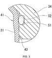
- a circumferential groove 51 is provided at the portion that corresponds to the insertion guide portion for the guide member 34 described above as shown in FIG. 3 and an O-ring 52 is provided in the circumferential groove 51, thus achieving a reliable seal between the guide member 34 and the case 31.
- cooling water can be more reliably prevented from entering the wax chamber from the gap between the guide member 34 and the case 31.
- the retainer 27 bears the biasing force of the coil spring 24b, and since the retainer 27 contacts the case 31 at the bottom of the case 31 at a location other than the coupling between the case 31 and the rod 38, the coupling is not subjected to the stress generated by the biasing force of the coil spring 24b. As a result, there is no possibility of the coupling shearing, making it possible to achieve a coupling of great strength with little energy when using connecting means such as spot welding or the like.
- the stress generated by the biasing force of the coil spring 24b can be dispersed and transmitted to the case 31, so that the load on the bottom of the case 31 can be reduced and its durability improved, and moreover the bottom of the case 31 does not deform.
- the coil spring 24b can have a longer set length, thus increasing design flexibility. Further, the small-diameter portion of the coil spring 24b at the element case end can be made comparative large, facilitating machining.
- the seating of the retainer 27 on the case 31 further improves deformation toughness of the bottom of the case 31 and the like due to internal pressure of the case when the wax 32 expands.
- the rod 38 can be made as large as necessary, thus providing greater design flexibility and securing an adequate coupling surface.
- the element case 31, on the one hand, and the other parts that adjoin it, slide over it, and contact it on the other, for example the poppet-shaped member that is the first valve 22, the rod 38, the frame 25, and the like that comprise the thermostat, can all be made of the same type of material, such as stainless steel.
- thermo-element 21 can be made thinner and lightweight.
- the element case 31 and the rod 38 are made of the same type of material (not limited to metallic material), then when using connecting means such as spot-welding or laser welding it is possible to achieve a coupling of great strength with little energy.
- the element case 31 and the poppet-shaped first valve 22 are made of the same type of material (not limited to metallic material), then by equalizing material characteristics (elastic deformation area, plastic deformation area) it becomes possible to fit these parts without extraordinary deformation or wear of one or the other, and even after fitting their mutual elasticity ensures a tight fit that improves water-tightness and reliability of the coupling.
- the present invention is not limited to the structures described in the embodiments described above, and the shapes, structures, and materials of the various parts that comprise the thermostat device 20 can be varied and changed as needed.
Landscapes
- Physics & Mathematics (AREA)
- Fluid Mechanics (AREA)
- General Physics & Mathematics (AREA)
- Engineering & Computer Science (AREA)
- Automation & Control Theory (AREA)
- Temperature-Responsive Valves (AREA)
Description
- The present invention relates to a temperature-sensitive automatic valve thermostat device used to control the temperature of cooling water in a cooling water circuit of an internal combustion engine (hereinafter "engine") used in an automobile or the like that circulates the cooling water between the engine and a heat exchanger (hereinafter "radiator") to cool the engine, in which the device operates on changes in the temperature of the cooling water to switch the flow of engine cooling water, and more particularly, to a thermo-element comprised of a thermal expansion unit that expands and contracts with changes in the temperature of the cooling water or other detected body and a moving member (a piston) moved by the expansion and contraction of the thermal expansion unit.
- In an automobile engine, for example, in order to cool the engine a water cooled-type cooling system using a radiator is generally employed. Conventionally, in this type of cooling system, a thermostat using a thermal expansion member or an electrically controlled valve unit that adjusts the volume of cooling water that is circulated to the radiator is employed in order to be able to control the temperature of the cooling water that is introduced into the engine.
- In the above-described thermostat device using a thermal expansion member, a control valve is disposed at a portion of the cooling water route, for example, at the intake or the exhaust ends of the route. If the cooling water temperature is too low, the control valve is closed, causing the cooling water to circulate through a bypass route without passing through the radiator. If the cooling water temperature has become too high, the control valve is opened, causing the cooling water to flow through the radiator. As a result, the temperature of the cooling water is maintained in the required state.
- Conventionally a variety of different structures for this type of thermostat device are known, having a first valve at one end of the thermo-element that operates by changes in the temperature of a fluid, a second valve at the other end of the thermo-element, biasing means that bias the first valve toward a closed position, and a frame.
- The thermo-element consists of a temperature sensor and a guide. A thermal expansion unit of wax or the like that senses the temperature of the fluid and expands and contracts is built into the temperature sensor. A piston is fitted into the guide, which protrudes from the tip of the temperature sensor. A flange configured as a single integrated unit with the frame is provided at the tip of the piston to hold back the piston.
- The first valve is poppet-shaped, and provided on the guide. The flange acts as the seat of the first valve. In addition, the flange has a mount projecting therefrom into the cooling water route.
- The second valve is mounted on a rod projecting from the distal end of the temperature sensor. Between the second valve and the temperature sensor, the second valve is spring-biased toward the tip of the rod.
- In this type of thermostat device, for example, the first valve is positioned to open and close the cooling water route and the second valve is positioned to open and close the bypass route. Then, the thermal expansion unit inside the temperature sensor expands as the temperature of the cooling water rises, pushing against the piston, and the thermo-element operates against the force of the biasing means. As a result, the fist valve moves to the open position and opens the cooling water route while the second valve moves to the closed position and closes the bypass route. Conversely, the thermal expansion unit contracts as the temperature of the cooling water declines and the pressure on the piston thus weakens, moving the first valve to the closed position to close the cooling water route while the second valve moves to the open position to open the bypass route. (See, for example, patent documents
JP-2004-177249-A JP-2004-308743-A - However, in the thermo-element having the conventional structure described above, the element case is made of stainless steel material and internal parts of the element case are configured with a structure that directly pushes out the piston using a U-shaped packing as a seal. In addition, with such a thermo-element, in an effort to reduce the number of parts, the amount of expensive and high-specific-gravity metal alloys such as brass, and cost, where used in an automobile thermostat the product weight decreases, thus providing advantages such as the ability to achieve improved fuel efficiency. Moreover, unlike the conventional brass case, the element case made of stainless steel material has a wide area of elastic deformation, with the advantage that it can absorb even sudden, drastic changes in internal pressure.
- However, with the thermo-element having the conventional structure described above, problems of machining and assembly arise during assembly of the thermo-element, leading to an increase in cost. Some sort of measure capable of solving such problems is sought.
- For example, a guide member that slidably holds the piston is inserted inside the thermo-element case, while the first valve is mounted and fixed on the outside. When such a first valve is fitted onto the case and fixed thereat, if the external diameter of the case is interfered with prior to such fitting, then the seal member cannot maintain a seal due to deformation of the case, for example, leading to inadequate durability (reliability). Moreover, there is the problem of an adverse effect on assembly.
- Further prior art is disclosed in documents
US 4 346 837 A andUS 7 175 102 B2 . These documents do, however, neither disclose nor give any hints for a satisfying solution of the above mentioned problems. - The present invention is conceived in light of the above-described circumstances and has as its object a thermostat device that provides an uncomplicated, easy-to-assemble element assembly including the thermo-element of the thermostat device that is compact and lightweight while also possessing superior strength, durability, and friction resistance.
- To achieve this object, the present invention (according to claim 1) provides a thermostat device having a thermal expansion unit that expands with a temperature increase and contracts with a temperature decrease, the thermal expansion unit built into an element case so as to be susceptible to effects of heat from outside the element case, the thermostat device having: a piston disposed inside the element case along an axial direction of the element case that advances and retreats with expansion and contraction of the thermal expansion unit, having an inner end that is immersed in the thermal expansion unit and an outer end that protrudes from an opening in one end of the element case; a guide member that is inserted into the element case from the opening in one end of the element case and slidably holds the piston; a seal member that is inserted into the element case from the opening in one end of the element case and holds the thermal expansion unit so that the thermal expansion unit does not leak from a chamber in which it is contained; and a first valve fitted onto the exterior of the element case near the opening in one end of the element case wherein the first valve (22) opens and closes a flowpath, wherein a portion of the element case for fitting the first valve onto the exterior of the element case, and portions of the element case for inserting the guide member and the seal member, are disposed so as to be offset in an axial direction and in a diametrical direction of the element case, a diameter of a portion of the element case that guides the first valve onto the element case is configured to be smaller than an outer diameter of the element case where the first valve is fitted onto the element case, and an inner diameter of the element case where the guide member and the seal member are inserted into the element case is configured to be smaller than an inner diameter of the element case where the first valve is fitted onto the element case, and the guide member is configured to be insertable in the element case without contacting an inner wall of the element case where the first valve is fitted onto the element case.
- The present invention (according to claim 2) provides the thermostat device according to claim 1, characterized in that the guide member inserted into the element case from one end thereof is provided with a circumferential groove, and an O-ring is provided in the circumferential groove that provides a seal between the element case and the guide member.
- The present invention (according to claim 3) provides the thermostat device according to claim 1, characterized in that a coil spring that biases a second valve is held by a coil spring bearing member, the coil spring bearing member being configured to contact the element case.
- As described above, according to the thermostat device of the present invention, because the fitted portion of the first valve that is fitted onto the exterior of the case and the portions of the seal between the case and the packing as well as the guide member that are inserted into the interior of the case are offset in the axial direction and in the diametrical direction of the case, despite the uncomplicated configuration, when the first valve is fitted it can be guided into place on the fitting portion of the case without harmful contact with the outer diameter of the element case corresponding to a chamber for the thermal expansion unit (wax), thus preventing the occurrence of unwanted variation in the amount of lift due to changes in the internal volume of the wax chamber. Moreover, the lack of harmful deformation of the seal has the advantage of improving the reliability of the seal against leakage of the thermal expansion unit (wax) after insertion and water-tightness of the inserted portion, as well as the reliability of the coupling.
- Further, according to the present invention, the configuration described above allows the element case to be made thinner, and that thinness can improve the responsiveness of the thermal element, in particular its temperature sensing and operating performance.
- In the thermostat device according to the present invention, the first valve is fitted after the thermal expansion unit (wax), the seal member (U packing), the buffer plate, and the guide member are inserted, the top of the case is capped and the element assembly is produced. If the inserted portions are not offset vertically (along the axis of the case) and in the diametrical direction of the case, the guide member would be improperly tightened as the first valve is guided into place and fitted and the portion of the guide member through which the piston slides would deform, increasing the sliding resistance of the piston and causing poor operation. In addition, if the fitted portion and the seal (inserted portion) of the U packing are not offset vertically (along the axis of the case) and in the diametrical direction of the case, the U packing would be improperly tightened as the first valve is guided into place and fitted and the portion of the guide member through which the piston slides would deform, affecting the case internal diameter dimensions at the seal and leading to an inability to secure a sufficient seal. In order to solve this problem, fitting the first valve first is conceivable, but doing so makes it impossible to secure sufficient insertion of the guide member and the U packing.
- It is also conceivable to shave (cut) the inside of the case in order to fit the first valve after production of the element assembly described above, or to cut the inserted portions of the guide member and the seal member. However, the increase in the number of production steps and the increase in the thickness of the case as a whole and its weight due to the need to take into account the amount that is cut away make this approach problematic.
- Further, because the inserted portion of the guide member and the fitted portion of the first valve are mutually offset, although at present the guide member is inserted first, conversely the first valve can be fitted first, thereby providing a greater degree of flexibility in the manufacturing process.
- In addition, because the internal diameter of the case corresponding to the fitted portion of the first valve is set larger than the internal diameter of the case for the inserted portions of the guide member and the seal member, it can function as an insertion guide portion for the guide member and the U packing, and the guide member and the U packing can be inserted easily.
- In particular, with the present invention, in addition to the fitted portion for the first valve, the portion for insertion of the guide member, and the portion for insertion of the U packing being offset along the axial direction of the case as described above, a step is provided so that the internal diameter of the case at the second portion for insertion of the guide member and the seal member into the case is smaller than the inner diameter of the case for fitting the first valve into place so as to form a space that can absorb the effects of any changes in the case internal diameter dimensions when the first valve is fitted into place, so that there is no risk of compressing the adjacent guide member and seal member.
- Moreover, since strict dimensional tolerances are not necessary, the device can be configured with more inexpensive parts. Further, when the element case is capped and the assembly is produced, even if the fitted portion where the first valve is fitted is deformed by the capping it can be absorbed by the above-described space and does not affect other parts, thereby improving durability and reliability as well.
- According to the present invention, by providing an O-ring in a circumferential groove of the guide member, entry of cooling water into the wax chamber from a gap between the guide member and the element case can be reliably prevented.
- According to the present invention, by providing the element case with a coil spring bearing member, the problems that occurred with the conventional structure in which a coil spring that biased a second valve so as to directly contact the element case, such as an inability to secure an adequate set length of the coil spring, difficulty with producing the small-diameter portion of the coil spring nearest the element case, limitations on the size of the rod, and stress on the joint between the element case and the rod causing breakage of the joint, can be reliably prevented.
- Further, according to the present invention, making the element case and the parts that comprise the thermostat, such as the first valve, the rod, the flange, the frame and the like of the same material makes it possible to obtain the following effects.
- If the element case and the frame are made of the same type of material, then, with respect to the sliding parts, whereas in the conventional brass element case the frame is usually made of a different material such as stainless steel, the soft case body is unilaterally worn away. However, by making the element case and the frame of the same type of material (such as stainless steel), unilateral wear on the case can be minimized and moreover the can be made thinner and lightweight.
- If the element case and the rod are made of the same type of material, then when using connecting means such as spot-welding it is possible to achieve a coupling of great strength with little energy.
- Further, if the element case and the first valve are made of the same type of material, then by equalizing material characteristics (elastic deformation area, plastic deformation area) it becomes possible to insert the parts without extraordinary unilateral deformation or wear of one or the other, and even after fitting their mutual elasticity ensures a tight fit that improves water-tightness and reliability of the coupling.
-
-
FIG. 1 is a schematic cross-sectional view of one embodiment of the thermostat device according to the present invention, showing the device as a whole; -
FIG. 2 is a partial enlarged cross-sectional view of main elements of the thermostat device according to the present invention, including an element case; and -
FIG. 3 is a partial enlarged cross-sectional view of main elements of another embodiment of the thermostat device according to the present invention. -
FIG. 1 shows one embodiment of a thermostat device according to the present invention. - In
FIG. 1 , in a cooling water circuit for an automobile engine, a temperature-sensitive automatic valve thermostat device denoted byreference numeral 20 is disposed where a bypass flow route from the engine exhaust side and a cooling water route of the radiator side intersect. Thethermostat device 20 is used to selectively switch the flow of cooling water through first and second fluid flowpaths comprised of these flow routes depending on the temperature of the cooling water and supply the cooling water to a cooling water route that extends to the engine intake. - As shown in
FIG. 1 , thethermostat device 20 has a thermo-element 21 as an operating part that operates on changes in temperature of the cooling water; first andsecond valves element 21 that open and close first and second fluid flowpaths; acoil spring 24a as a biasing means that biases thefirst valve 22 toward a closed position; acoil spring 24b as a biasing means that biases thesecond valve 23 toward a closed position; aframe 25 that surrounds these elements; and a coil spring bearing member (retainer) 27. - On top of the
frame 25, and attached to theframe 25, is aflange 26 having an upwardly projectingengagement portion 26a that engages a top tip of a later-described piston of the thermo-element 21. A gasket is provided to an outer circumference of theflange 26, and is retained and held in place to maintain watertightness of a portion of a device housing. Avalve seat 26b for thefirst valve 22 is provided on an inner edge portion of theflange 26. Thus is configured the first valve that controls the flow of the cooling water in the first fluid flowpath. - The thermo-
element 21 is configured as shown. - More specifically, the thermo-
element 21 includes ametal element case 31 composed of a hollow container that is cylindrical in shape, has a bottom, and is substantially uniform in diameter, into the bottom of whichwax 32 is inserted as a thermal expansion unit that thermally expands and thermally contracts when subjected to the effects of heat from an external source. - The
element case 31 is pressed or cast, and comprised of a material such as stainless steel. - A
piston 33 is disposed inside thecase 31 along the axial direction thereof, an inner end of which is immersed in thewax 32 and an outer end of which protrudes from an opening in thecase 31. Thepiston 33 is configured to advance and retreat along the axis with the expansion and contraction of thewax 32. Retraction of thepiston 33 into the interior of thecase 31 is carried out by the biasing force of an externally provided return spring or the like (in the present embodiment, thecoil spring 24a). - In the drawing,
reference numeral 34 denotes a guide member that slidably holds thepiston 33. Theguide member 34 is formed into a substantially cylindrical shape, and is inserted into the interior of thecase 31 from one end (the open end) thereof. - A U packing 35 is disposed at an inner end of the
guide member 34 inside thecase 31 as a seal member that seals thewax 32 in the bottom of thecase 31.Reference numeral 34a in the drawing denotes a through-hole that slidably holds thepiston 33. -
Reference numeral 39 denotes a back-up plate interposed between the U packing 35 and theguide member 34 inside thecase 31, which prevents entry of packing subjected to the force of expansion of the wax into the gap between the guide and the case and between the piston and the guide. - A poppet-shaped member (22) having a substantially poppet-like shape that engages the outer end of the
guide member 34 is fitted onto an outer peripheral portion of the opening in thecase 31 and inserted, to form a single integrated unit with thefirst valve 22. - In
FIG. 1 ,reference numeral 22a denotes a covering composed of a heat-resistant compound resin or rubber member. Thecovering 22a covers the surface of ametal core 22b of the poppet-shapedmember 22, and functions as a seat portion that is seated on thevalve seat 26b. - In addition, in
FIG. 1 ,reference numeral 37 denotes a boot covering the outer end side of theguide 34. - Further,
reference numeral 38 denotes a rod fixedly attached to the bottom of thecase 31 by soldering or the like and extending axially therealong. - The
thermostat device 20 described above is produced by inserting the thermal expansion unit (wax) 32, the U packing 35, and the back-upplate 39 into the interior of thecase 31, then inserting theguide member 34 and capping the top of thecase 31 to produce the element assembly, after which the first valve (the poppet-shaped member) 22 is pressed into place and the flange, frame, and other parts are assembled. - The thermo-
element 21 configured as described above resolves all the problems of the hitherto common sleeve-type or diaphragm-type thermo-element, holds the number of constituent parts to the minimum required, reduces costs, and moreover provides reciprocal movement of the necessary stroke of the piston due to volumetric changes attendant upon expansion and contraction of the thermal expansion unit, as well as superior responsiveness and durability. - Further, in the above-described thermo-
element 21, the shape and structure of thecase 31, theguide member 34, and the like are greatly simplified, providing the advantage of even more effective thinness, compactness, processing, assembly, cost reduction, and lightness. - In the
thermostat device 20 having the configuration described above, when the cooling water temperature is low the piston 3 is immersed in thewax 32 and protrudes only a relatively small amount from thecase 31. At this time, the thermo-element 21 is biased by the force of thecoil spring 24a upward in the drawing, closing thefirst valve 22. - As the temperature of the cooling water rises, that state is transmitted to the temperature sensor of the thermo-
element 21 and thewax 32 expands, pushing thepiston 33 out. At this time, because thepiston 33 is engaged by theflange 26, thecase 31 of the thermo-element 21 moves downward, opening thefirst valve 22. - The
rod 38 passes through a hole in the center of theretainer 27, and theretainer 27 is contacted against theelement case 31 by the force of the coil spring at at least one place other than a coupling between it and therod 38, such as a tapered part of theretainer 27. The point of contact with thecoil spring 24b is higher than the junction between the element case and the rod. The tapered portion contacts theelement case 31 at a hemispherical portion of great strength that forms the bottom of theelement case 31. Further, theretainer 27 may contact theelement case 31 at two places on a flanged-shapedshoulder 27a of theretainer 27. - In the
thermostat device 20 configured as described above, according to the present invention, as shown inFIG. 2 , aportion 41 of the case where the poppet-shaped member (22) that is the first valve having the shape of a poppet is fitted onto the exterior of thecase 31, first andsecond portions guide member 34 is inserted into the interior of thecase 31, and a portion of the case where the seal member (U packing) 35 is inserted into the interior of thecase 31 are arranged so as to be offset in the axial direction and in the diametrical direction of thecase 31. At the same time, the inner diameter of thecase 31 where the poppet-shapedmember 22 is guided onto thecase 31 is configured to be smaller than the inner diameter of thecase 31 where the poppet-shapedmember 22 is fitted onto the case, and moreover, the inner diameter of the case at thesecond portion 43 of the case and the portion of the case where the seal member (U packing) 35 are inserted is configured to be smaller than the inner diameter of theportion 41 of the case where the first valve (poppet-shaped member) 22 is fitted onto the case. - Further, the inner diameter of a
guide member 34 first inserted portion of thecase 31 is configured to be larger than the inner diameter of thecase 31 where thefirst valve 22 is fitted onto thecase 31. - With such a configuration, a step is provided that guides the poppet-shaped first valve (poppet-shaped member) 22 accurately onto the
portion 41, such that, when the first valve (poppet-shaped member) 22 is fitted, it can be guided into place on the portion without harmful contact with the outer diameter of theelement case 31 corresponding to a chamber for the thermal expansion unit (the wax), and moreover, with the advantage that the reliability of water-tightness and coupling after fitting can be improved. - Moreover, because the
guide member 34 avoids the inner wall of the case at thecase portion 41 onto which the first valve is fitted and is held at two places by thefirst portion 42 and thesecond portion 43 of the case, fixing in place while axially deviated or slanted can be prevented more securely than when held at only one place, thus improving durability and reliability. - Here, "insertion" of the
guide member 34 includes fitting or engaging to the extent that the guide member is fixedly held within the case. Provided that it is fixedly held, the shapes of the guide member and the inner diameter of the case into which the guide member is inserted can each be different. - According to the present invention, because a step is provided on the
element case 31 during formation, the above-described cutting step becomes unnecessary. Moreover, because thecase 31 is thinner, a reduction in weight as well as improved responsiveness is achieved. - Further, because the first and
second portions guide member 34 and theportion 41 for the first valve (poppet-shaped member) 22 are offset in mutually different ways, although at present theguide member 34 is inserted first, conversely, even if the first valve (poppet-shaped member) 22 were fitted into place first it would not affect the portions of the case for theguide member 31 and the seal member (U packing) 35, thereby providing a greater degree of flexibility in the manufacturing process. - In addition, because the inside of the
case 31 corresponding to theportion 41 of the case for the first valve (poppet-shaped member) 22 functions as an insertion guide portion for theguide member 34 and the U packing 35, theguide member 34 and the U packing 35 can be inserted easily. - In particular, with the above-described configuration, in addition to the
portion 41 for the first valve (poppet-shaped member) 22, the portion for insertion of theguide member 34, and further the portion for insertion of the U packing 35 being offset along the axial direction of thecase 31 as described above, first andsecond portions guide member 34 while avoiding the inner wall of thecase 31 are provided, with a step provided so that the diameter of the case at the second portion for insertion of theguide member 34 is smaller than the inner diameter of thecase 31 for fitting the first valve into place so as to form a space, such that when the first valve (poppet-shaped member) 22 is fitted into place the first valve (poppet-shaped member) 22 does not compress the seal (the U packing 35) and theguide member 34. - It should be noted that the
guide member 34 first insertedportion 42 is formed so as to retain the first valve, and is set larger than the fitted portion diameter. This portion also functions as an insertion guide for the guide and the U packing. - Moreover, although in the present embodiment guide insertion portions are provided at two places, provided that the problem of axial deviation like that described above can be solved, the guide may be fixedly held in place at only one of the first and
second portions - Further, the portion of the
case 31 for guiding the first valve into place may be given a tapered shape of decreasing diameter from the insertion portion to the bottom of thecase 31. - Moreover, when the
element case 31 is capped and the element assembly is completed, even if the inserted portion of the first valve has been deformed by such capping the above-described space can absorb it. That is, if there is no such space the stress of fitting falls on theguide member 34, theseal 35, or the portions of the case corresponding to where these are inserted, and the guide member and theseal 35 will deform. - Preferably, a
circumferential groove 51 is provided at the portion that corresponds to the insertion guide portion for theguide member 34 described above as shown inFIG. 3 and an O-ring 52 is provided in thecircumferential groove 51, thus achieving a reliable seal between theguide member 34 and thecase 31. - By so doing, cooling water can be more reliably prevented from entering the wax chamber from the gap between the
guide member 34 and thecase 31. - Further, by providing the
case 31 with theretainer 27 according to the present invention, theretainer 27 bears the biasing force of thecoil spring 24b, and since theretainer 27 contacts thecase 31 at the bottom of thecase 31 at a location other than the coupling between thecase 31 and therod 38, the coupling is not subjected to the stress generated by the biasing force of thecoil spring 24b. As a result, there is no possibility of the coupling shearing, making it possible to achieve a coupling of great strength with little energy when using connecting means such as spot welding or the like. - Preferably, by contacting the
case 31 at multiple places with theshoulder 27a of the flange portion of theretainer 27 or the like, the stress generated by the biasing force of thecoil spring 24b can be dispersed and transmitted to thecase 31, so that the load on the bottom of thecase 31 can be reduced and its durability improved, and moreover the bottom of thecase 31 does not deform. - Moreover, because the point of contact between the
coil spring 24b and theretainer 27 is higher than the coupling between thecase 31 and therod 38, thecoil spring 24b can have a longer set length, thus increasing design flexibility. Further, the small-diameter portion of thecoil spring 24b at the element case end can be made comparative large, facilitating machining. - Further, the seating of the
retainer 27 on thecase 31 further improves deformation toughness of the bottom of thecase 31 and the like due to internal pressure of the case when thewax 32 expands. - In addition, because it is not necessary to provide a contact part on the bottom of the
case 31 for thecoil spring 24b as has conventionally been the case, therod 38 can be made as large as necessary, thus providing greater design flexibility and securing an adequate coupling surface. - It should be noted that in the above-described
thermostat device 20 theelement case 31, on the one hand, and the other parts that adjoin it, slide over it, and contact it on the other, for example the poppet-shaped member that is thefirst valve 22, therod 38, theframe 25, and the like that comprise the thermostat, can all be made of the same type of material, such as stainless steel. - In a configuration of this type, if for example the
element case 31 and theframe 25 are made of the same type of material, then, with respect to the sliding parts, whereas in the conventional brass element case the case body is unilaterally worn away, the thermo-element becomes slanted and invites malfunctioning, by contrast, where the material is of the same type (for example, stainless steel), wear on thecase 31 can be minimized and moreover the thermo-element 21 can be made thinner and lightweight. - If the
element case 31 and therod 38 are made of the same type of material (not limited to metallic material), then when using connecting means such as spot-welding or laser welding it is possible to achieve a coupling of great strength with little energy. - Further, if the
element case 31 and the poppet-shapedfirst valve 22 are made of the same type of material (not limited to metallic material), then by equalizing material characteristics (elastic deformation area, plastic deformation area) it becomes possible to fit these parts without extraordinary deformation or wear of one or the other, and even after fitting their mutual elasticity ensures a tight fit that improves water-tightness and reliability of the coupling. - By making the
element case 31 and the other parts that adjoin it, slide over it, and contact it of the same material, galvanic corrosion can be prevented. - The present invention is not limited to the structures described in the embodiments described above, and the shapes, structures, and materials of the various parts that comprise the
thermostat device 20 can be varied and changed as needed.
Claims (3)
- A thermostat device (20) having a thermal expansion unit (32) that expands with a temperature increase and contracts with a temperature decrease, the thermal expansion unit (32) built into an element case (31) so as to be susceptible to effects of heat from outside the element case (31), the thermostat device (20) having:a piston (33) disposed inside the element case (31) along an axial direction of the element case (31) that advances and retreats with expansion and contraction of the thermal expansion unit (32), having an inner end that is immersed in the thermal expansion unit (32) and an outer end that protrudes from an opening in one end of the element case (31);a guide member (34) that is inserted into the element case (31) from the opening in one end of the element case (31) and slidably holds the piston (33);a seal member (35) that is inserted into the element case (31) from the opening in one end of the element case (31) and holds the thermal expansion unit (32) so that the thermal expansion unit (32) does not leak from a chamber in which it is contained; anda first valve (22) fitted onto the exterior of the element case (31) near the opening in one end of the element case (31) wherein the first valve (22) opens and closes a flowpath,wherein a portion (41) of the element case (31) for fitting the first valve (22) onto the exterior of the element case (31), and portions (42) of the element case (31) for inserting the guide member (34) and the seal member (35), are disposed so as to be offset in an axial direction and in a diametrical direction of the element case (31),a diameter of a portion (41) of the element case (31) that guides the first valve (22) onto the element case (31) is configured to be smaller than an outer diameter of the element case (31) where the first valve (22) is fitted onto the element case (31), and an inner diameter of the element case (31) where the guide member (34) and the seal member (35) are inserted into the element case (31) is configured to be smaller than an inner diameter of the element case (31) where the first valve (22) is fitted onto the element case (31), and
the guide member (34) is configured to be insertable in the element case (31) without contacting an inner wall of the element case (31) where the first valve (22) is fitted onto the element case (31). - The thermostat device (20) according to claim 1, characterized in that the guide member (34) inserted into the element case (31) from one end thereof is provided with a circumferential groove (51), and an O-ring (52) is provided in the circumferential groove (51) that provides a seal between the element case (31) and the guide member (34).
- The thermostat device (20) according to claim 1, characterized in that a coil spring (24b) that biases a second valve (23) is held by a coil spring bearing member (27),
the coil spring bearing member (27) being configured to contact the element case (31).
Applications Claiming Priority (2)
| Application Number | Priority Date | Filing Date | Title |
|---|---|---|---|
| JP2009106902A JP5288614B2 (en) | 2009-04-24 | 2009-04-24 | Thermostat device |
| PCT/JP2010/052296 WO2010122832A1 (en) | 2009-04-24 | 2010-02-17 | Thermostat device |
Publications (3)
| Publication Number | Publication Date |
|---|---|
| EP2423548A1 EP2423548A1 (en) | 2012-02-29 |
| EP2423548A4 EP2423548A4 (en) | 2017-03-29 |
| EP2423548B1 true EP2423548B1 (en) | 2019-05-01 |
Family
ID=43010956
Family Applications (1)
| Application Number | Title | Priority Date | Filing Date |
|---|---|---|---|
| EP10766892.3A Active EP2423548B1 (en) | 2009-04-24 | 2010-02-17 | Thermostat device |
Country Status (8)
| Country | Link |
|---|---|
| US (1) | US8893979B2 (en) |
| EP (1) | EP2423548B1 (en) |
| JP (1) | JP5288614B2 (en) |
| CN (1) | CN102414494B (en) |
| ES (1) | ES2741540T3 (en) |
| HU (1) | HUE044684T2 (en) |
| PT (1) | PT2423548T (en) |
| WO (1) | WO2010122832A1 (en) |
Families Citing this family (19)
| Publication number | Priority date | Publication date | Assignee | Title |
|---|---|---|---|---|
| KR101355544B1 (en) * | 2012-03-08 | 2014-02-05 | 한국델파이주식회사 | Bypass valve for transmission oil air-cooler, assembling method of the bypass valve, and transmission oil air-cooler including the bypass valve |
| JP2013241918A (en) * | 2012-05-22 | 2013-12-05 | Nippon Thermostat Co Ltd | Thermostat device |
| FR2991008B1 (en) | 2012-05-23 | 2015-07-17 | Vernet | THERMOSTATIC ELEMENT |
| KR101875625B1 (en) * | 2012-10-08 | 2018-07-06 | 현대자동차 주식회사 | Thermostat |
| US20140097259A1 (en) * | 2012-10-09 | 2014-04-10 | Hyundai Motor Company | Thermostat |
| DE102013111618A1 (en) * | 2013-10-22 | 2015-04-23 | Dr. Ing. H.C. F. Porsche Aktiengesellschaft | thermostatic valve |
| JP2015086974A (en) * | 2013-10-31 | 2015-05-07 | ヤマハ発動機株式会社 | Thermostat, water cooling device, water cooling engine, and outboard engine |
| US9772632B1 (en) * | 2013-11-25 | 2017-09-26 | Richard Michael Ihns | Bypass valve |
| US20160108796A1 (en) * | 2014-10-17 | 2016-04-21 | Hyundai Motor Company | Thermostat |
| FR3049326B1 (en) | 2016-03-23 | 2018-04-20 | Vernet | THERMOSTATIC VALVE FOR A FLUID CIRCUIT CIRCUIT, AND METHOD OF MANUFACTURING SUCH A THERMOSTATIC VALVE |
| US20200063882A1 (en) * | 2017-04-07 | 2020-02-27 | Nok Corporation | Opening and closing valve structure for thermostat device |
| US10824177B2 (en) * | 2018-11-19 | 2020-11-03 | Hamilton Sundstrand Corporation | Thermal wax bypass valve utilizing rigid seal carrier |
| FR3103021B1 (en) * | 2019-11-13 | 2022-01-21 | Vernet | Thermostatic device for regulating the circulation of a fluid, as well as corresponding thermostatic valve and method of manufacturing such a device |
| US10989100B1 (en) * | 2020-03-27 | 2021-04-27 | Thomas Kubsch | Engine cooling system and thermostat thermal actuator with a degassing two-stage piston |
| KR102341571B1 (en) * | 2020-06-30 | 2021-12-22 | 인지컨트롤스 주식회사 | Thermostat apparatus |
| CN117321294A (en) * | 2021-05-14 | 2023-12-29 | 日本调温器株式会社 | Temperature regulating device |
| CN113803516A (en) * | 2021-11-19 | 2021-12-17 | 潍坊康斯拓普温控卫浴有限公司 | Anti-clamping stagnation constant temperature element |
| WO2024054175A1 (en) * | 2022-09-05 | 2024-03-14 | Kirpart Otomotiv Parcalari Sanayi Ve Ticaret Anonim Sirketi | A thermoelement that responds more quickly to the temperature of the coolant fluid |
| JP7453720B1 (en) | 2023-12-25 | 2024-03-21 | 富士精工株式会社 | Wax thermoelement and wax thermoelement manufacturing method |
Family Cites Families (11)
| Publication number | Priority date | Publication date | Assignee | Title |
|---|---|---|---|---|
| JPS6316943Y2 (en) * | 1980-01-29 | 1988-05-13 | ||
| JPS60121598U (en) * | 1984-01-25 | 1985-08-16 | 三菱重工業株式会社 | Lubricating oil equipment |
| JPS6351979U (en) * | 1986-09-20 | 1988-04-07 | ||
| US4802621A (en) * | 1986-09-25 | 1989-02-07 | Consolidated Controls Corporation | Thermal modulating control valve |
| US5445318A (en) * | 1993-06-24 | 1995-08-29 | Nicolas Pinilla | Thermostatic safety valve for a hydraulic cooling circuit |
| JPH10288037A (en) * | 1997-04-11 | 1998-10-27 | Giichi Kuze | Wax type thermostat having high cooling efficiency for automobile engine |
| JP3005606B2 (en) * | 1998-05-22 | 2000-01-31 | 富士精工株式会社 | Thermal response valve for controlling the refrigerant circuit of an automobile engine |
| JP4293506B2 (en) | 2002-11-27 | 2009-07-08 | 日本サーモスタット株式会社 | Thermo element |
| JP4400909B2 (en) * | 2003-04-04 | 2010-01-20 | 日本サーモスタット株式会社 | Thermostat device |
| JP4225551B2 (en) * | 2004-05-21 | 2009-02-18 | 日本サーモスタット株式会社 | Thermostat device |
| CA2727578C (en) * | 2008-07-10 | 2016-02-09 | Nippon Thermostat Co., Ltd. | Thermostat device |
-
2009
- 2009-04-24 JP JP2009106902A patent/JP5288614B2/en active Active
-
2010
- 2010-02-17 US US13/255,098 patent/US8893979B2/en active Active
- 2010-02-17 HU HUE10766892 patent/HUE044684T2/en unknown
- 2010-02-17 PT PT10766892T patent/PT2423548T/en unknown
- 2010-02-17 ES ES10766892T patent/ES2741540T3/en active Active
- 2010-02-17 EP EP10766892.3A patent/EP2423548B1/en active Active
- 2010-02-17 CN CN2010800176598A patent/CN102414494B/en active Active
- 2010-02-17 WO PCT/JP2010/052296 patent/WO2010122832A1/en active Application Filing
Non-Patent Citations (1)
| Title |
|---|
| None * |
Also Published As
| Publication number | Publication date |
|---|---|
| CN102414494A (en) | 2012-04-11 |
| EP2423548A4 (en) | 2017-03-29 |
| WO2010122832A1 (en) | 2010-10-28 |
| PT2423548T (en) | 2019-08-19 |
| JP2010255758A (en) | 2010-11-11 |
| EP2423548A1 (en) | 2012-02-29 |
| CN102414494B (en) | 2013-08-07 |
| US8893979B2 (en) | 2014-11-25 |
| HUE044684T2 (en) | 2019-11-28 |
| JP5288614B2 (en) | 2013-09-11 |
| US20120097750A1 (en) | 2012-04-26 |
| ES2741540T3 (en) | 2020-02-11 |
Similar Documents
| Publication | Publication Date | Title |
|---|---|---|
| EP2423548B1 (en) | Thermostat device | |
| EP2857652B1 (en) | Thermostat device | |
| US7665976B2 (en) | High pressure fuel pump for internal combustion engine | |
| PL191786B1 (en) | Hydraulic play taking up system | |
| US9650947B1 (en) | Air bypass valve | |
| KR20180111937A (en) | Thermostat and temperature control system | |
| US10302208B2 (en) | Control valve with external relief bias member | |
| JP6090605B2 (en) | Air bypass valve | |
| US9377789B2 (en) | Thermostat | |
| JP6025006B1 (en) | Air bypass valve | |
| US20170254254A1 (en) | Thermostatic valve having a sleeve | |
| JP6257037B2 (en) | Thermostat device | |
| CN109780310B (en) | Temperature regulating valve | |
| CN109780259B (en) | Temperature regulating valve | |
| CN109780258B (en) | Temperature regulating valve | |
| WO2019091481A1 (en) | Thermostatic valve | |
| EP3096055B1 (en) | Air bypass valve | |
| US12007796B2 (en) | Thermostatic valve | |
| US20140097259A1 (en) | Thermostat | |
| CN110630784B (en) | Temperature regulating valve | |
| CN110410566B (en) | Temperature regulating valve and thermal management system with same | |
| CN110410568B (en) | Temperature regulating valve and thermal management system with same | |
| EP4105457A1 (en) | Valve unit | |
| CN110410525B (en) | Temperature regulating valve and thermal management system with same | |
| CN112747167B (en) | Temperature regulating valve |
Legal Events
| Date | Code | Title | Description |
|---|---|---|---|
| PUAI | Public reference made under article 153(3) epc to a published international application that has entered the european phase |
Free format text: ORIGINAL CODE: 0009012 |
|
| 17P | Request for examination filed |
Effective date: 20110909 |
|
| AK | Designated contracting states |
Kind code of ref document: A1 Designated state(s): AT BE BG CH CY CZ DE DK EE ES FI FR GB GR HR HU IE IS IT LI LT LU LV MC MK MT NL NO PL PT RO SE SI SK SM TR |
|
| DAX | Request for extension of the european patent (deleted) | ||
| RA4 | Supplementary search report drawn up and despatched (corrected) |
Effective date: 20170228 |
|
| RIC1 | Information provided on ipc code assigned before grant |
Ipc: F01P 7/16 20060101ALI20170222BHEP Ipc: G05D 23/02 20060101ALI20170222BHEP Ipc: F16K 31/68 20060101AFI20170222BHEP |
|
| STAA | Information on the status of an ep patent application or granted ep patent |
Free format text: STATUS: EXAMINATION IS IN PROGRESS |
|
| 17Q | First examination report despatched |
Effective date: 20180309 |
|
| GRAP | Despatch of communication of intention to grant a patent |
Free format text: ORIGINAL CODE: EPIDOSNIGR1 |
|
| STAA | Information on the status of an ep patent application or granted ep patent |
Free format text: STATUS: GRANT OF PATENT IS INTENDED |
|
| INTG | Intention to grant announced |
Effective date: 20181128 |
|
| GRAS | Grant fee paid |
Free format text: ORIGINAL CODE: EPIDOSNIGR3 |
|
| GRAA | (expected) grant |
Free format text: ORIGINAL CODE: 0009210 |
|
| STAA | Information on the status of an ep patent application or granted ep patent |
Free format text: STATUS: THE PATENT HAS BEEN GRANTED |
|
| AK | Designated contracting states |
Kind code of ref document: B1 Designated state(s): AT BE BG CH CY CZ DE DK EE ES FI FR GB GR HR HU IE IS IT LI LT LU LV MC MK MT NL NO PL PT RO SE SI SK SM TR |
|
| REG | Reference to a national code |
Ref country code: GB Ref legal event code: FG4D |
|
| REG | Reference to a national code |
Ref country code: CH Ref legal event code: EP Ref country code: AT Ref legal event code: REF Ref document number: 1127381 Country of ref document: AT Kind code of ref document: T Effective date: 20190515 |
|
| REG | Reference to a national code |
Ref country code: DE Ref legal event code: R096 Ref document number: 602010058592 Country of ref document: DE |
|
| REG | Reference to a national code |
Ref country code: IE Ref legal event code: FG4D |
|
| REG | Reference to a national code |
Ref country code: PT Ref legal event code: SC4A Ref document number: 2423548 Country of ref document: PT Date of ref document: 20190819 Kind code of ref document: T Free format text: AVAILABILITY OF NATIONAL TRANSLATION Effective date: 20190801 |
|
| REG | Reference to a national code |
Ref country code: NL Ref legal event code: MP Effective date: 20190501 |
|
| REG | Reference to a national code |
Ref country code: LT Ref legal event code: MG4D |
|
| PG25 | Lapsed in a contracting state [announced via postgrant information from national office to epo] |
Ref country code: NL Free format text: LAPSE BECAUSE OF FAILURE TO SUBMIT A TRANSLATION OF THE DESCRIPTION OR TO PAY THE FEE WITHIN THE PRESCRIBED TIME-LIMIT Effective date: 20190501 Ref country code: HR Free format text: LAPSE BECAUSE OF FAILURE TO SUBMIT A TRANSLATION OF THE DESCRIPTION OR TO PAY THE FEE WITHIN THE PRESCRIBED TIME-LIMIT Effective date: 20190501 Ref country code: LT Free format text: LAPSE BECAUSE OF FAILURE TO SUBMIT A TRANSLATION OF THE DESCRIPTION OR TO PAY THE FEE WITHIN THE PRESCRIBED TIME-LIMIT Effective date: 20190501 Ref country code: SE Free format text: LAPSE BECAUSE OF FAILURE TO SUBMIT A TRANSLATION OF THE DESCRIPTION OR TO PAY THE FEE WITHIN THE PRESCRIBED TIME-LIMIT Effective date: 20190501 Ref country code: NO Free format text: LAPSE BECAUSE OF FAILURE TO SUBMIT A TRANSLATION OF THE DESCRIPTION OR TO PAY THE FEE WITHIN THE PRESCRIBED TIME-LIMIT Effective date: 20190801 Ref country code: FI Free format text: LAPSE BECAUSE OF FAILURE TO SUBMIT A TRANSLATION OF THE DESCRIPTION OR TO PAY THE FEE WITHIN THE PRESCRIBED TIME-LIMIT Effective date: 20190501 |
|
| REG | Reference to a national code |
Ref country code: HU Ref legal event code: AG4A Ref document number: E044684 Country of ref document: HU |
|
| PG25 | Lapsed in a contracting state [announced via postgrant information from national office to epo] |
Ref country code: GR Free format text: LAPSE BECAUSE OF FAILURE TO SUBMIT A TRANSLATION OF THE DESCRIPTION OR TO PAY THE FEE WITHIN THE PRESCRIBED TIME-LIMIT Effective date: 20190802 Ref country code: BG Free format text: LAPSE BECAUSE OF FAILURE TO SUBMIT A TRANSLATION OF THE DESCRIPTION OR TO PAY THE FEE WITHIN THE PRESCRIBED TIME-LIMIT Effective date: 20190801 Ref country code: LV Free format text: LAPSE BECAUSE OF FAILURE TO SUBMIT A TRANSLATION OF THE DESCRIPTION OR TO PAY THE FEE WITHIN THE PRESCRIBED TIME-LIMIT Effective date: 20190501 |
|
| REG | Reference to a national code |
Ref country code: AT Ref legal event code: MK05 Ref document number: 1127381 Country of ref document: AT Kind code of ref document: T Effective date: 20190501 |
|
| PG25 | Lapsed in a contracting state [announced via postgrant information from national office to epo] |
Ref country code: IS Free format text: LAPSE BECAUSE OF FAILURE TO SUBMIT A TRANSLATION OF THE DESCRIPTION OR TO PAY THE FEE WITHIN THE PRESCRIBED TIME-LIMIT Effective date: 20190901 |
|
| PG25 | Lapsed in a contracting state [announced via postgrant information from national office to epo] |
Ref country code: EE Free format text: LAPSE BECAUSE OF FAILURE TO SUBMIT A TRANSLATION OF THE DESCRIPTION OR TO PAY THE FEE WITHIN THE PRESCRIBED TIME-LIMIT Effective date: 20190501 Ref country code: DK Free format text: LAPSE BECAUSE OF FAILURE TO SUBMIT A TRANSLATION OF THE DESCRIPTION OR TO PAY THE FEE WITHIN THE PRESCRIBED TIME-LIMIT Effective date: 20190501 Ref country code: SK Free format text: LAPSE BECAUSE OF FAILURE TO SUBMIT A TRANSLATION OF THE DESCRIPTION OR TO PAY THE FEE WITHIN THE PRESCRIBED TIME-LIMIT Effective date: 20190501 Ref country code: AT Free format text: LAPSE BECAUSE OF FAILURE TO SUBMIT A TRANSLATION OF THE DESCRIPTION OR TO PAY THE FEE WITHIN THE PRESCRIBED TIME-LIMIT Effective date: 20190501 Ref country code: RO Free format text: LAPSE BECAUSE OF FAILURE TO SUBMIT A TRANSLATION OF THE DESCRIPTION OR TO PAY THE FEE WITHIN THE PRESCRIBED TIME-LIMIT Effective date: 20190501 |
|
| REG | Reference to a national code |
Ref country code: DE Ref legal event code: R097 Ref document number: 602010058592 Country of ref document: DE |
|
| REG | Reference to a national code |
Ref country code: ES Ref legal event code: FG2A Ref document number: 2741540 Country of ref document: ES Kind code of ref document: T3 Effective date: 20200211 |
|
| PG25 | Lapsed in a contracting state [announced via postgrant information from national office to epo] |
Ref country code: SM Free format text: LAPSE BECAUSE OF FAILURE TO SUBMIT A TRANSLATION OF THE DESCRIPTION OR TO PAY THE FEE WITHIN THE PRESCRIBED TIME-LIMIT Effective date: 20190501 |
|
| PLBE | No opposition filed within time limit |
Free format text: ORIGINAL CODE: 0009261 |
|
| STAA | Information on the status of an ep patent application or granted ep patent |
Free format text: STATUS: NO OPPOSITION FILED WITHIN TIME LIMIT |
|
| 26N | No opposition filed |
Effective date: 20200204 |
|
| PG25 | Lapsed in a contracting state [announced via postgrant information from national office to epo] |
Ref country code: PL Free format text: LAPSE BECAUSE OF FAILURE TO SUBMIT A TRANSLATION OF THE DESCRIPTION OR TO PAY THE FEE WITHIN THE PRESCRIBED TIME-LIMIT Effective date: 20190501 |
|
| PG25 | Lapsed in a contracting state [announced via postgrant information from national office to epo] |
Ref country code: SI Free format text: LAPSE BECAUSE OF FAILURE TO SUBMIT A TRANSLATION OF THE DESCRIPTION OR TO PAY THE FEE WITHIN THE PRESCRIBED TIME-LIMIT Effective date: 20190501 |
|
| REG | Reference to a national code |
Ref country code: CH Ref legal event code: PL |
|
| REG | Reference to a national code |
Ref country code: BE Ref legal event code: MM Effective date: 20200229 |
|
| PG25 | Lapsed in a contracting state [announced via postgrant information from national office to epo] |
Ref country code: MC Free format text: LAPSE BECAUSE OF FAILURE TO SUBMIT A TRANSLATION OF THE DESCRIPTION OR TO PAY THE FEE WITHIN THE PRESCRIBED TIME-LIMIT Effective date: 20190501 Ref country code: LU Free format text: LAPSE BECAUSE OF NON-PAYMENT OF DUE FEES Effective date: 20200217 |
|
| PG25 | Lapsed in a contracting state [announced via postgrant information from national office to epo] |
Ref country code: LI Free format text: LAPSE BECAUSE OF NON-PAYMENT OF DUE FEES Effective date: 20200229 Ref country code: CH Free format text: LAPSE BECAUSE OF NON-PAYMENT OF DUE FEES Effective date: 20200229 |
|
| PG25 | Lapsed in a contracting state [announced via postgrant information from national office to epo] |
Ref country code: IE Free format text: LAPSE BECAUSE OF NON-PAYMENT OF DUE FEES Effective date: 20200217 |
|
| PG25 | Lapsed in a contracting state [announced via postgrant information from national office to epo] |
Ref country code: BE Free format text: LAPSE BECAUSE OF NON-PAYMENT OF DUE FEES Effective date: 20200229 |
|
| PG25 | Lapsed in a contracting state [announced via postgrant information from national office to epo] |
Ref country code: MT Free format text: LAPSE BECAUSE OF FAILURE TO SUBMIT A TRANSLATION OF THE DESCRIPTION OR TO PAY THE FEE WITHIN THE PRESCRIBED TIME-LIMIT Effective date: 20190501 Ref country code: CY Free format text: LAPSE BECAUSE OF FAILURE TO SUBMIT A TRANSLATION OF THE DESCRIPTION OR TO PAY THE FEE WITHIN THE PRESCRIBED TIME-LIMIT Effective date: 20190501 |
|
| PG25 | Lapsed in a contracting state [announced via postgrant information from national office to epo] |
Ref country code: MK Free format text: LAPSE BECAUSE OF FAILURE TO SUBMIT A TRANSLATION OF THE DESCRIPTION OR TO PAY THE FEE WITHIN THE PRESCRIBED TIME-LIMIT Effective date: 20190501 |
|
| P01 | Opt-out of the competence of the unified patent court (upc) registered |
Effective date: 20230420 |
|
| PGFP | Annual fee paid to national office [announced via postgrant information from national office to epo] |
Ref country code: ES Payment date: 20240304 Year of fee payment: 15 |
|
| PGFP | Annual fee paid to national office [announced via postgrant information from national office to epo] |
Ref country code: HU Payment date: 20240111 Year of fee payment: 15 Ref country code: DE Payment date: 20231228 Year of fee payment: 15 Ref country code: CZ Payment date: 20240129 Year of fee payment: 15 Ref country code: GB Payment date: 20240109 Year of fee payment: 15 Ref country code: PT Payment date: 20240216 Year of fee payment: 15 |
|
| PGFP | Annual fee paid to national office [announced via postgrant information from national office to epo] |
Ref country code: TR Payment date: 20240209 Year of fee payment: 15 Ref country code: IT Payment date: 20240111 Year of fee payment: 15 Ref country code: FR Payment date: 20240103 Year of fee payment: 15 |