EP2423539B1 - Dichtungsanordnung - Google Patents
Dichtungsanordnung Download PDFInfo
- Publication number
- EP2423539B1 EP2423539B1 EP10174738.4A EP10174738A EP2423539B1 EP 2423539 B1 EP2423539 B1 EP 2423539B1 EP 10174738 A EP10174738 A EP 10174738A EP 2423539 B1 EP2423539 B1 EP 2423539B1
- Authority
- EP
- European Patent Office
- Prior art keywords
- ring
- sealing
- seal arrangement
- sealing ring
- ring carrier
- Prior art date
- Legal status (The legal status is an assumption and is not a legal conclusion. Google has not performed a legal analysis and makes no representation as to the accuracy of the status listed.)
- Active
Links
Images

Classifications
-
- F—MECHANICAL ENGINEERING; LIGHTING; HEATING; WEAPONS; BLASTING
- F16—ENGINEERING ELEMENTS AND UNITS; GENERAL MEASURES FOR PRODUCING AND MAINTAINING EFFECTIVE FUNCTIONING OF MACHINES OR INSTALLATIONS; THERMAL INSULATION IN GENERAL
- F16J—PISTONS; CYLINDERS; SEALINGS
- F16J15/00—Sealings
- F16J15/16—Sealings between relatively-moving surfaces
- F16J15/18—Sealings between relatively-moving surfaces with stuffing-boxes for elastic or plastic packings
- F16J15/24—Sealings between relatively-moving surfaces with stuffing-boxes for elastic or plastic packings with radially or tangentially compressed packing
-
- F—MECHANICAL ENGINEERING; LIGHTING; HEATING; WEAPONS; BLASTING
- F16—ENGINEERING ELEMENTS AND UNITS; GENERAL MEASURES FOR PRODUCING AND MAINTAINING EFFECTIVE FUNCTIONING OF MACHINES OR INSTALLATIONS; THERMAL INSULATION IN GENERAL
- F16J—PISTONS; CYLINDERS; SEALINGS
- F16J9/00—Piston-rings, e.g. non-metallic piston-rings, seats therefor; Ring sealings of similar construction
- F16J9/06—Piston-rings, e.g. non-metallic piston-rings, seats therefor; Ring sealings of similar construction using separate springs or elastic elements expanding the rings; Springs therefor ; Expansion by wedging
-
- F—MECHANICAL ENGINEERING; LIGHTING; HEATING; WEAPONS; BLASTING
- F04—POSITIVE - DISPLACEMENT MACHINES FOR LIQUIDS; PUMPS FOR LIQUIDS OR ELASTIC FLUIDS
- F04B—POSITIVE-DISPLACEMENT MACHINES FOR LIQUIDS; PUMPS
- F04B39/00—Component parts, details, or accessories, of pumps or pumping systems specially adapted for elastic fluids, not otherwise provided for in, or of interest apart from, groups F04B25/00 - F04B37/00
- F04B39/04—Measures to avoid lubricant contaminating the pumped fluid
- F04B39/041—Measures to avoid lubricant contaminating the pumped fluid sealing for a reciprocating rod
- F04B39/042—Measures to avoid lubricant contaminating the pumped fluid sealing for a reciprocating rod sealing being provided on the piston
-
- F—MECHANICAL ENGINEERING; LIGHTING; HEATING; WEAPONS; BLASTING
- F04—POSITIVE - DISPLACEMENT MACHINES FOR LIQUIDS; PUMPS FOR LIQUIDS OR ELASTIC FLUIDS
- F04B—POSITIVE-DISPLACEMENT MACHINES FOR LIQUIDS; PUMPS
- F04B53/00—Component parts, details or accessories not provided for in, or of interest apart from, groups F04B1/00 - F04B23/00 or F04B39/00 - F04B47/00
- F04B53/14—Pistons, piston-rods or piston-rod connections
- F04B53/143—Sealing provided on the piston
-
- F—MECHANICAL ENGINEERING; LIGHTING; HEATING; WEAPONS; BLASTING
- F16—ENGINEERING ELEMENTS AND UNITS; GENERAL MEASURES FOR PRODUCING AND MAINTAINING EFFECTIVE FUNCTIONING OF MACHINES OR INSTALLATIONS; THERMAL INSULATION IN GENERAL
- F16J—PISTONS; CYLINDERS; SEALINGS
- F16J15/00—Sealings
- F16J15/16—Sealings between relatively-moving surfaces
- F16J15/26—Sealings between relatively-moving surfaces with stuffing-boxes for rigid sealing rings
- F16J15/28—Sealings between relatively-moving surfaces with stuffing-boxes for rigid sealing rings with sealing rings made of metal
-
- F—MECHANICAL ENGINEERING; LIGHTING; HEATING; WEAPONS; BLASTING
- F16—ENGINEERING ELEMENTS AND UNITS; GENERAL MEASURES FOR PRODUCING AND MAINTAINING EFFECTIVE FUNCTIONING OF MACHINES OR INSTALLATIONS; THERMAL INSULATION IN GENERAL
- F16J—PISTONS; CYLINDERS; SEALINGS
- F16J15/00—Sealings
- F16J15/16—Sealings between relatively-moving surfaces
- F16J15/32—Sealings between relatively-moving surfaces with elastic sealings, e.g. O-rings
- F16J15/3268—Mounting of sealing rings
- F16J15/3272—Mounting of sealing rings the rings having a break or opening, e.g. to enable mounting on a shaft otherwise than from a shaft end
-
- F—MECHANICAL ENGINEERING; LIGHTING; HEATING; WEAPONS; BLASTING
- F16—ENGINEERING ELEMENTS AND UNITS; GENERAL MEASURES FOR PRODUCING AND MAINTAINING EFFECTIVE FUNCTIONING OF MACHINES OR INSTALLATIONS; THERMAL INSULATION IN GENERAL
- F16J—PISTONS; CYLINDERS; SEALINGS
- F16J15/00—Sealings
- F16J15/56—Other sealings for reciprocating rods
-
- F—MECHANICAL ENGINEERING; LIGHTING; HEATING; WEAPONS; BLASTING
- F16—ENGINEERING ELEMENTS AND UNITS; GENERAL MEASURES FOR PRODUCING AND MAINTAINING EFFECTIVE FUNCTIONING OF MACHINES OR INSTALLATIONS; THERMAL INSULATION IN GENERAL
- F16J—PISTONS; CYLINDERS; SEALINGS
- F16J9/00—Piston-rings, e.g. non-metallic piston-rings, seats therefor; Ring sealings of similar construction
- F16J9/10—Special members for adjusting the rings
-
- F—MECHANICAL ENGINEERING; LIGHTING; HEATING; WEAPONS; BLASTING
- F16—ENGINEERING ELEMENTS AND UNITS; GENERAL MEASURES FOR PRODUCING AND MAINTAINING EFFECTIVE FUNCTIONING OF MACHINES OR INSTALLATIONS; THERMAL INSULATION IN GENERAL
- F16J—PISTONS; CYLINDERS; SEALINGS
- F16J9/00—Piston-rings, e.g. non-metallic piston-rings, seats therefor; Ring sealings of similar construction
- F16J9/12—Details
- F16J9/14—Joint-closures
- F16J9/16—Joint-closures obtained by stacking of rings
-
- F—MECHANICAL ENGINEERING; LIGHTING; HEATING; WEAPONS; BLASTING
- F16—ENGINEERING ELEMENTS AND UNITS; GENERAL MEASURES FOR PRODUCING AND MAINTAINING EFFECTIVE FUNCTIONING OF MACHINES OR INSTALLATIONS; THERMAL INSULATION IN GENERAL
- F16J—PISTONS; CYLINDERS; SEALINGS
- F16J9/00—Piston-rings, e.g. non-metallic piston-rings, seats therefor; Ring sealings of similar construction
- F16J9/12—Details
- F16J9/22—Rings for preventing wear of grooves or like seatings
-
- F—MECHANICAL ENGINEERING; LIGHTING; HEATING; WEAPONS; BLASTING
- F16—ENGINEERING ELEMENTS AND UNITS; GENERAL MEASURES FOR PRODUCING AND MAINTAINING EFFECTIVE FUNCTIONING OF MACHINES OR INSTALLATIONS; THERMAL INSULATION IN GENERAL
- F16J—PISTONS; CYLINDERS; SEALINGS
- F16J15/00—Sealings
- F16J15/16—Sealings between relatively-moving surfaces
- F16J15/18—Sealings between relatively-moving surfaces with stuffing-boxes for elastic or plastic packings
- F16J15/181—Sealings between relatively-moving surfaces with stuffing-boxes for elastic or plastic packings for plastic packings
-
- F—MECHANICAL ENGINEERING; LIGHTING; HEATING; WEAPONS; BLASTING
- F16—ENGINEERING ELEMENTS AND UNITS; GENERAL MEASURES FOR PRODUCING AND MAINTAINING EFFECTIVE FUNCTIONING OF MACHINES OR INSTALLATIONS; THERMAL INSULATION IN GENERAL
- F16J—PISTONS; CYLINDERS; SEALINGS
- F16J9/00—Piston-rings, e.g. non-metallic piston-rings, seats therefor; Ring sealings of similar construction
- F16J9/28—Piston-rings, e.g. non-metallic piston-rings, seats therefor; Ring sealings of similar construction of non-metals
Definitions
- the invention relates to a seal assembly for reciprocating compressors.
- the publication WO 97/00397 discloses a multi-piece sealing ring consisting of three segments. These segments are subject to wear during operation, with the Segmentation of the sealing ring has the consequence that the contact pressure of the segments on the piston rod and thus the sealing effect is maintained despite the wear thanks to a self-adjustment of the segments up to a predetermined wear limit.
- Such a multi-part sealing ring thus has a wear compensation by the segments move automatically depending on the wear.
- the publication WO 97/00396 discloses a one-piece sealing ring which is suitable as a piston rod seal arrangement.
- This sealing ring comprises a single one-piece ring with a push.
- the wear compensation is effected by an elastic and / or plastic deformation of the sealing ring.
- the sealing rings of a piston rod packing are pressed in the unloaded state, for example by a hose spring to the piston rod.
- an additional contact pressure of the sealing ring to the piston rod is effected by the voltage applied to the sealing ring differential pressure an additional contact pressure of the sealing ring to the piston rod.
- an additional contact pressure of the sealing ring to the piston rod is effected by the voltage applied to the sealing ring differential pressure.
- an additional contact pressure of the sealing ring to the piston rod effected by the voltage applied to the sealing ring differential pressure an additional contact pressure of the sealing ring to the piston rod.
- elastic and / or plastic deformation of the sealing ring or the individual segments which among other things uneven material removal along the circumference of the sealing ring result.
- These effects occur, in particular, in sealing arrangements arranged directly towards the compression space, since these sealing arrangements are usually loaded with a time-varying pressure difference. The load has the consequence that this seal assembly has a rapidly decreasing sealing effect, and that depends on the material used the sealing rings flow or a break
- the object of the invention is to form an economically advantageous sealing arrangement.
- a sealing arrangement comprising a deformable ring carrier and a first and a second endless sealing ring, wherein the ring carrier has a perpendicular to the circumferential direction extending longitudinal axis, and wherein the ring carrier in the circumferential direction has a gap with play, and wherein each sealing ring a longitudinal axis extending perpendicular to its circumferential direction, and wherein the sealing rings are arranged such that the ring carrier surrounds them from the outside, and wherein the two sealing rings are arranged side by side in the longitudinal direction of the longitudinal axis, and wherein the ring carrier and the sealing rings are configured so adapted to each other in that the first sealing ring rests on one side against a first side wall of the ring carrier and on the opposite side with respect to the longitudinal axis of the first sealing ring Side forms a first gap to the ring carrier, and wherein the second sealing ring abuts gegen malaria one side to a second side wall of the ring carrier and forms
- the inventive sealing arrangement has the advantage that the actual sealing rings no longer have bumps by the sealing rings are designed as endless sealing rings. This means that the sealing ring runs over 360 ° and has no gap or impact but is configured throughout over a full circle of 360 °.
- the inventive seal assembly with sealing rings without bumps thus has the advantage that the pressure changes and pressure differences acting on the sealing ring have no or only a very small instability of the sealing ring result, so that the sealing ring has a much lower wear compared to known seal assemblies.
- the ring carrier is designed in a preferred embodiment such that it encloses the two sealing rings in such a way that the two sealing rings are displaceably mounted in the opposite direction.
- the ring carrier in the circumferential direction has a gap, wherein the ring carrier is formed of a deformable material and is designed elastically or plastically deformable, which has the consequence that the ring carrier can change its diameter in the radial direction, and thereby a force or can cause a shift to the two sealing rings.
- the sealing arrangement comprises a hose spring or a clamping ring, which surrounds the ring carrier at the periphery thereof to effect a force on the sealing rings at least in the unloaded state and thus to ensure that they remain in contact with the piston rod in the unloaded state ,
- the ring carrier has a shock, wherein the sealing rings are arranged in the ring carrier and held mutually displaceable, that the displacement direction of the two sealing rings is aligned orthogonal or perpendicular to the direction of the shock.
- each sealing ring only over an angle of 180 degrees or essentially has a frictional contact with the piston rod 180 degrees, and thus rests only along this angle on the piston rod circumference.
- An asymmetric material removal thus takes place on each of the two sealing rings, with the result that they move towards one another during operation or during wear.
- the ring carrier and the two sealing rings are designed in a particularly advantageous embodiment of each other adapted so that the maximum permissible wear path of the sealing rings is limited, which is possible, for example, by eccentric incorporated in the ring carrier grooves.
- the ring carrier no longer exerts the forces acting in the opposite direction on the sealing rings.
- the sealing function of the sealing arrangement thus changes from a friction seal into a gap seal, preferably a contact-free gap seal.
- the sealing arrangement according to the invention has, inter alia, the advantage that the sealing rings are configured endlessly, that is, that the sealing rings have no cut or gap, which is why the sealing rings have a high rigidity, so that the compressive forces acting on the sealing ring cause less deformation, which in turn As a result, the wear is reduced.
- the sealing rings also need no elastic or plastic deformability for wear compensation, as was required in previously known sealing rings. This makes it possible to form a seal assembly with low wear.
- the wear direction of the two sealing rings is predetermined by the ring carrier, for example by eccentric shaped grooves which hold the sealing rings, so that no rotation is required by a fixing pin in the seal assembly, so that the seal assembly can be designed low and reliable.
- the ring carrier of the sealing arrangement is designed such that the two sealing rings are held in the axial direction by the ring carrier in a mutually spaced position by the ring carrier has a spacer ring, which is arranged between the sealing rings.
- the spacer ring is designed such that its inside comes to rest near the piston rod or rests against the piston rod and thus likewise exerts a sealing function. If the spacer ring rests against the piston rod, a frictional contact results along the piston rod in that the first sealing ring has a 180 degree contact with the piston rod. Thereafter, the spacer ring has a frictional contact with the piston rod, and then the second sealing ring has a 180 degree contact with the piston rod.
- the ring carrier causes a pressure-relieving function for the sealing rings.
- the sealing rings are guided in the lateral direction through the spacer ring.
- the sealing rings are preferably made of dry running materials such as filled PTFE or specially modified for dry-running polymer blends or high-temperature polymers such as PEEK or PI and special sintered bronze.
- the sealing rings consist for example of filled plastics and fiber composite materials or of metal such as lead or tin bronze.
- the ring carrier is preferably made of a plastic such as PEEK. If the ring carrier has a contact with the piston rod, so is preferably a modified plastic containing solid lubricants such as graphite or PTFE suitable.
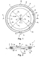
- FIG. 1 shows in a supervision and in FIG. 2 in a section along the section line AA a seal assembly 1 comprising an elastically or plastically deformable ring carrier 2 and a first and a second endless sealing ring 3a, 3b, which are arranged in the ring carrier 2.
- Under an endless sealing ring is understood to mean a 360 ° extending ring, which thus has no gap or no impact point.
- the ring carrier 2 has a longitudinal axis L extending perpendicular to its circumferential direction.
- the ring carrier 2 also has in the circumferential direction of a gap 2i with game T.
- Each sealing ring 3a, 3b has a longitudinal axis 3c, 3d which runs perpendicular to its circumferential direction.
- the sealing rings 3a, 3b are arranged such that the ring carrier 2 surrounds them from the outside, wherein the two sealing rings 3a, 3b as shown FIG. 2 can be seen lying in the direction of the longitudinal axis L immediately adjacent to each other.
- the ring carrier 2 and the sealing rings 3a, 3b are designed in a new condition, ie without or with only little wear and fitting to a piston rod 6, adapted to one another such that the first sealing ring 3a on one side to a first side wall 2d of the ring carrier 2 rests and on the relative to the longitudinal axis 3c of the first sealing ring 3a opposite side forms a first gap S1 to the ring carrier 2, and that the second sealing ring 3b gegentechnisch abuts on one side on a second side wall 21 of the ring carrier 2 and on the respect to the longitudinal axis 3d of the second sealing ring 3b opposite side forms a second gap S2 to the ring carrier 2, wherein the first and second side wall 2d, 21 are arranged opposite to the
- the above-described arrangement of the ring carrier 2 and the two sealing rings 3a, 3b applies in particular when new and as long as the sealing rings 3a, 3b have no or only a slight closure.
- the sealing rings 3a, 3b are arranged in a starting position along a piston rod 6, wherein the two sealing rings 3a, 3b are preferably arranged in such a manner on the piston rod 6, that the longitudinal axes 3c, 3d are identical.
- the ring carrier 2 has a recess 2 f, in which a clamping ring 4 is arranged and the ring carrier 2 encloses.
- the ring carrier 2 has a web 2h to prevent rotation of the clamping ring 4 with respect to the ring carrier 2.
- the in the Figures 1 and 2 illustrated seal assembly 1 shows the designed as an annular body ring carrier 2 with gap 2i.
- the view according to FIG. 1 in particular shows the second sealing ring 3b and the surrounding this ring carrier 2.
- the ring carrier 2 has on the inside thereof configured side walls, that they cause the oppositely acting biasing forces 5a, 5b on the first and second sealing ring 3a, 3b, wherein the clamping ring 4 a Pretension on the ring carrier 2 exerts.
- the ring carrier 2 on the inside shown on the left has a semicircular second side wall 21 with center Z1 and radius R2.
- the ring carrier 2 has a semicircular second extending on the inside shown on the right spaced side wall 2m with center Z2 and radius R3, wherein in the illustrated embodiment, the radii R2 and R3 are identical.
- the two centers Z1 and Z2 are mutually spaced by a distance Z, the distance Z depending on the embodiment of the ring carrier 2 or depending on the maximum allowable wear of the sealing rings 3a, 3b may have a value between 0, 1 and 10 mm. According to the view from FIG.
- first side wall 2d and the first spaced side wall 2e are formed so as to be semicircular with center Z1 and radius R2 and the first spaced side wall 2e is semicircular is configured with center Z3 and radius R3, wherein the radii R2 and R3 are again identical in the illustrated embodiment.
- the two centers Z1 and Z3 are in turn spaced apart by the distance Z.
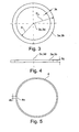
- FIG. 3 shows in a plan view of the endless sealing ring 3a and 3b with central axis 3c, 3d, inner radius R, outer radius R1 and ring width 3k.
- FIG. 4 shows a side view of the endless sealing ring 3a, 3b with width 3g.
- FIG. 5 shows in a plan view the clamping ring 4 with gap 4a and gap width 4b.
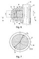
- FIG. 6 shows a movable in the direction of movement v piston rod 6 with longitudinal axis M.
- FIG. 6 in a partial longitudinal section, the left half of a seal assembly 1, which in a
- FIG. 6 shows a similar, as in FIGS. 1 and 2 illustrated seal assembly 1, wherein in FIG. 6 illustrated seal assembly 1 is also in new condition. The design and operation of this seal assembly 1 has already been with the help of FIG. 2 described.
- FIG. 7 shows a section through a piston rod 6, for example along the section line BB according to FIG. 6 with sealing ring 3b bearing against the piston rod 6 when new.
- the longitudinal axis M of the piston rod 6 is identical or almost identical to the center axis 3d of the sealing ring 3b.
- the inner radius R of the sealing ring 3b is greater than or equal to the radius R5 of the piston rod.
- FIG. 8 shows the in FIG. 7 shown view after a certain period of operation during which the sealing rings 3a, 3b are subject to wear.
- the force acting on the second sealing ring 3b biasing force 5b has the consequence that the second sealing ring 3b in the illustration according to FIG. 8 Wears on the inner surface of the left side, said inner surface abuts the surface of the piston rod 6, so that on the right side between the piston rod 6 and the second sealing ring 3b, a gap S6 is formed.
- the first sealing ring 3a undergoes a comparison with respect to the second sealing ring 3a wear and therefore performs a gegen Dermate movement in the direction of the biasing force 5a, so that between the piston rod 6 and the first sealing ring 3a, a gap S3 forms.
- FIG. 8 shows the in FIG. 7 shown view after a certain period of operation during which the sealing rings 3a, 3b are subject to wear.
- the force acting on the second sealing ring 3b biasing force 5b has the consequence that the second sealing
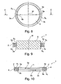
- FIG. 9 shows a section along the in FIG. 8 illustrated section line CC, where in FIG. 9 also still the first and second sealing ring 3a, 3b enclosing Ring carrier 2 is shown.
- the wear of the first and second sealing ring 3a, 3b has the result that the columns S3, S4, S5 and S6 form, wherein the seal assembly 1, as shown in FIG FIG. 9 can be seen, despite these columns S3, S4, S5 and S6 in the longitudinal direction M of the piston rod L has an excellent sealing effect.
- FIG. 9 shows a section along the in FIG. 8 illustrated section line CC, where in FIG. 9 also still the first and second sealing ring 3a, 3b enclosing Ring carrier 2 is shown.
- the wear of the first and second sealing ring 3a, 3b has the result that the columns S3, S4, S5 and S6 form, wherein the seal assembly 1, as shown in FIG FIG. 9 can be seen, despite these columns S3, S4, S5 and S6 in the longitudinal direction M of the piston rod L
- the sealing function of the sealing arrangement 1 changes from a friction seal into a gap seal, preferably into a contact-free gap seal.
- FIG. 10 shows in a section a further embodiment of a sealing arrangement 1.
- the seal assembly 1 according to FIG. 10 a ring carrier 2 with a configured as an intermediate wall ring part 2k, against which the two sealing rings 3a, 3b, so that the two sealing rings 3a, 3b are arranged mutually spaced in the direction of the longitudinal axis L.
- the ring part 2k is also referred to as a spacer ring 2k.
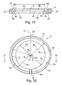
- FIG. 12 shows a plan view of a similar, as in FIG. 10 illustrated ring carrier 2.
- FIG. 11 shows a section along the section line DD according to FIG. 12 .
- the ring carrier 2 has a recess 2a for the first sealing ring 3a and a recess 2b for the second sealing ring 3b.
- the ring carrier 2 also has an annular part 2k or an intermediate web 2k, with a recess 2c for the piston rod 6, wherein the recess preferably has a surface aligned against the piston rod 6, as shown, wherein the annular part 2k is preferably designed such that between Ring part 2k and piston rod 6 forms a gap, so that a gap seal is formed.
- the intermediate web 2k has an inner diameter which substantially corresponds to the inner diameter R of the first and second sealing ring 3a, 3b.
- the course of the grooves for receiving the first and second sealing ring 3a, 3b is identical insofar as in FIG. 1 illustrated configured as the recess 2b for the second sealing ring 3b has a semicircular second side wall 21 with radius of curvature R2 and center Z1 and a semicircular spaced side wall 2m with radius of curvature R3 and center Z2.
- the ring part 2k has, inter alia, the advantage that it forms a supporting side surface for the sealing ring 3a, 3b, so that it is better guided at attacking alternating loads.
- the ring member 2k together with the piston rod 6 in the longitudinal direction L form a gap seal.
- FIG. 13 shows a further embodiment of a ring carrier 2 and FIG. 14 shows a matched to this ring carrier 2 second sealing ring 3b.
- the in FIG. 13 Ring carrier 2 shown a recess 2b with a circular side wall with center Z1 and radius R2, so that the second side edge 21 and the spaced side wall 2m are circular, with the same center Z1.
- the second sealing ring 3b can still move in the recess 2b of the ring carrier 2, as in FIGS. 1 and 2 described, the second sealing ring 3b as in FIG. 14 designed configured.
- the second sealing ring 3b has a first, semi-circular outer surface 3h with center Z1 and radius R1.
- the second sealing ring 3b also has a second, semi-circular outer surface 3i with center Z3 and radius R1.
- the two centers Z1 and Z3 are mutually spaced by the distance Z.
- the second sealing ring 3b thus has in FIG. 14 on the right side on a smaller width, with the result that this sealing ring 3b, arranged in the recess 2b of in FIG. 13 shown ring carrier 2, in the new state, a gap S2 between the spaced side wall 2m of the ring carrier 2 and the second semicircular outer surface 3i is formed.
- the first sealing ring 3a is designed exactly the same as in FIG. 14 illustrated second sealing ring 3b, wherein the first sealing ring 3a so gegen Sammlung the second sealing ring 3b in the in FIG. 13 arranged ring carrier 2 is arranged that in the new state such as in FIG. 2 shown on the left side forms a gap S1.
- the ring carrier 2 and / or the sealing ring 3a, 3b in the in the FIGS. 13 and 14 embodiment shown a rotation, not shown, for example, a bolt to fix the position of the sealing ring 3a, 3b with respect to the ring carrier such that no mutual rotation occurs.
- the side walls 21, 2m of the recess for receiving the first and second sealing ring 3a, 3b determine recesses 2a, 2b in the ring carrier 2 and the outer surfaces 3h, 3i of the sealing rings 3a, 3b can be designed in a variety of ways so mutually adapted that the sealing ring 3a, 3b in the direction of the attacking biasing force 5a, 5b is slidably mounted in the ring carrier 2.
- the side walls 21,2m and / or the outer surface 3h, 3i could, for example, also be designed as a polygonal or polygonal line, or for example could also be oval.
- the ring carrier 2 and the sealing rings 3a, 3b are preferably adapted to one another in such a way that the first and / or second gap S1, S2 has a maximum width in the range of 0.1 mm to 10 mm when new, and preferably a maximum width in the Range of 1 mm to 2 mm.
- the sealing rings 3a, 3b are preferably made of a wearable material, in particular of a metal such as bronze, gray cast iron or sintered iron or of a plastic such as PEEK, filled PTFE or high-temperature polymers such as PEEK, PI or epoxy.
- the ring carrier 2 consists of a metal, in particular of steel, stainless steel, bronze or gray cast iron, or of a plastic, in particular made of PEEK, filled PTFE or high-temperature polymers such as PEEK, PI or epoxy.
- a plurality of seal assemblies 1 can be arranged one behind the other.
Landscapes
- Engineering & Computer Science (AREA)
- General Engineering & Computer Science (AREA)
- Mechanical Engineering (AREA)
- Sealing Devices (AREA)
- Compressor (AREA)
Priority Applications (5)
| Application Number | Priority Date | Filing Date | Title |
|---|---|---|---|
| EP10174738.4A EP2423539B1 (de) | 2010-08-31 | 2010-08-31 | Dichtungsanordnung |
| PCT/EP2011/065054 WO2012028661A1 (de) | 2010-08-31 | 2011-08-31 | Dichtungsanordnung |
| JP2013526463A JP5837595B2 (ja) | 2010-08-31 | 2011-08-31 | 密封装置 |
| US13/819,606 US8985588B2 (en) | 2010-08-31 | 2011-08-31 | Seal arrangement |
| CN201180052388.4A CN103201541B (zh) | 2010-08-31 | 2011-08-31 | 密封装置 |
Applications Claiming Priority (1)
| Application Number | Priority Date | Filing Date | Title |
|---|---|---|---|
| EP10174738.4A EP2423539B1 (de) | 2010-08-31 | 2010-08-31 | Dichtungsanordnung |
Publications (2)
| Publication Number | Publication Date |
|---|---|
| EP2423539A1 EP2423539A1 (de) | 2012-02-29 |
| EP2423539B1 true EP2423539B1 (de) | 2014-04-02 |
Family
ID=43768989
Family Applications (1)
| Application Number | Title | Priority Date | Filing Date |
|---|---|---|---|
| EP10174738.4A Active EP2423539B1 (de) | 2010-08-31 | 2010-08-31 | Dichtungsanordnung |
Country Status (5)
| Country | Link |
|---|---|
| US (1) | US8985588B2 (enExample) |
| EP (1) | EP2423539B1 (enExample) |
| JP (1) | JP5837595B2 (enExample) |
| CN (1) | CN103201541B (enExample) |
| WO (1) | WO2012028661A1 (enExample) |
Families Citing this family (16)
| Publication number | Priority date | Publication date | Assignee | Title |
|---|---|---|---|---|
| US20100090149A1 (en) * | 2008-10-01 | 2010-04-15 | Compressor Engineering Corp. | Poppet valve assembly, system, and apparatus for use in high speed compressor applications |
| CN103046172A (zh) * | 2012-12-23 | 2013-04-17 | 经纬纺织机械股份有限公司 | 精梳机牵伸加压气缸接触环 |
| WO2015050624A2 (en) * | 2013-08-02 | 2015-04-09 | United Technologies Corporation | Gas turbine engine non-rotating structure wedge seal |
| EP3080490B1 (en) | 2013-12-10 | 2019-02-20 | Howden Thomassen Compressors B.V. | Single seal ring stuffing box |
| CN105650281A (zh) * | 2016-03-12 | 2016-06-08 | 哈电集团哈尔滨电站阀门有限公司 | 石墨金属组合式密封环 |
| DE102016108393B4 (de) * | 2016-05-06 | 2022-09-08 | Volkswagen Aktiengesellschaft | Mehrteiliger Ölabstreifring |
| US20170335972A1 (en) * | 2016-05-17 | 2017-11-23 | Compressor Products International, Llc | Rod packing |
| CN107542722A (zh) * | 2017-07-25 | 2018-01-05 | 盐城美希密封件有限公司 | 一种耐高温高压动密封结构 |
| US10436322B2 (en) * | 2017-08-09 | 2019-10-08 | Etagen, Inc. | Piston sealing ring assemblies |
| JP7002401B2 (ja) * | 2018-04-27 | 2022-02-10 | 株式会社神戸製鋼所 | 圧縮機 |
| EP3875807A1 (de) * | 2020-03-03 | 2021-09-08 | Burckhardt Compression AG | Kolbenringanordnung, kolbenverdichter sowie verfarhen zum abdichten eines verdichtungsraums |
| CN111911627A (zh) * | 2020-04-30 | 2020-11-10 | 湖北金稽山机械科技有限公司 | 工程塑料耐磨面浮动油封 |
| DK181183B1 (en) * | 2022-03-02 | 2023-04-12 | Man Energy Solutions Filial Af Man Energy Solutions Se Tyskland | Piston ring for a large two-stroke turbo-charged uniflow-scavenged crosshead internal combustion engine |
| US12435661B1 (en) * | 2024-04-08 | 2025-10-07 | Pratt & Whitney Canada Corp. | Rotary engine with seal having shield and elastomeric member |
| CN118128906B (zh) * | 2024-05-10 | 2024-07-05 | 广汉鸿达硬质合金有限责任公司 | 一种组合式密封环 |
| CN120140314A (zh) * | 2025-03-14 | 2025-06-13 | 迈欣机械无锡有限公司 | 一种液压执行器 |
Family Cites Families (17)
| Publication number | Priority date | Publication date | Assignee | Title |
|---|---|---|---|---|
| US1407714A (en) * | 1921-03-28 | 1922-02-28 | Whitcomb Lee | Piston ring |
| US1774002A (en) * | 1928-02-16 | 1930-08-26 | Hazlett M Hardy | Compression and oil-control piston ring |
| US1917639A (en) * | 1932-12-24 | 1933-07-11 | Dora B Evans | Pump piston |
| DE1926102A1 (de) * | 1969-05-22 | 1970-11-26 | Borsig Gmbh | Dichtung fuer Kolbenstangen und Kolben von Kolbenmaschinen fuer hohe Druecke |
| US3711104A (en) | 1971-03-16 | 1973-01-16 | Dresser Ind | Seal assembly |
| US3999767A (en) * | 1972-07-12 | 1976-12-28 | A-T-O Inc. | Piston ring system |
| JPS579359A (en) | 1980-06-17 | 1982-01-18 | Toshiba Corp | Shaft sealing apparatus |
| JPS6040860U (ja) * | 1983-08-30 | 1985-03-22 | 日立建機株式会社 | 油圧シリンダとロツド間のシ−ル構造 |
| JP2553203B2 (ja) * | 1988-10-31 | 1996-11-13 | 株式会社東芝 | 極低温冷凍機 |
| US5347915A (en) * | 1991-11-06 | 1994-09-20 | Maschinenfabrik Sulzer-Burckhardt Ag | Piston compressor for the oilfree compression of gases |
| TW305915B (enExample) * | 1995-06-14 | 1997-05-21 | Burckhardt Ag Maschf | |
| TW434375B (en) | 1995-06-14 | 2001-05-16 | Burckhardt Ag Maschf | Sealing ring |
| TW312740B (enExample) | 1995-06-14 | 1997-08-11 | Burckhardt Ag Maschf | |
| EP1275888B1 (de) * | 2001-07-09 | 2004-12-01 | Burckhardt Compression AG | Kolbenring |
| DE102005059926A1 (de) * | 2005-12-13 | 2007-06-21 | Carl Freudenberg Kg | Dichtring und Dichtungsanordnung sowie deren Verwendung |
| AT505293B1 (de) | 2007-11-15 | 2008-12-15 | Hoerbiger Kompressortech Hold | Packungsring-kombination |
| DE102008037746A1 (de) | 2008-08-14 | 2010-02-18 | Märkisches Werk GmbH | Ringdichtung |
-
2010
- 2010-08-31 EP EP10174738.4A patent/EP2423539B1/de active Active
-
2011
- 2011-08-31 US US13/819,606 patent/US8985588B2/en active Active
- 2011-08-31 WO PCT/EP2011/065054 patent/WO2012028661A1/de not_active Ceased
- 2011-08-31 CN CN201180052388.4A patent/CN103201541B/zh active Active
- 2011-08-31 JP JP2013526463A patent/JP5837595B2/ja active Active
Also Published As
| Publication number | Publication date |
|---|---|
| JP2013540961A (ja) | 2013-11-07 |
| CN103201541B (zh) | 2015-05-27 |
| WO2012028661A1 (de) | 2012-03-08 |
| JP5837595B2 (ja) | 2015-12-24 |
| US20130154197A1 (en) | 2013-06-20 |
| US8985588B2 (en) | 2015-03-24 |
| CN103201541A (zh) | 2013-07-10 |
| EP2423539A1 (de) | 2012-02-29 |
Similar Documents
| Publication | Publication Date | Title |
|---|---|---|
| EP2423539B1 (de) | Dichtungsanordnung | |
| EP2056003B1 (de) | Mehrteiliger Packungsring | |
| EP2912351B1 (de) | Kolbenring | |
| AT505293B1 (de) | Packungsring-kombination | |
| EP0985108B1 (de) | Dichtelement für trockenlaufsysteme und verwendung eines solchen dichtelements | |
| EP3555502B1 (de) | Kolbenring für einen kolbenverdichter sowie kolbenverdichter | |
| EP3918232B1 (de) | Packungsring mit entlastungsöffnungen | |
| EP3919784B1 (de) | Kolbenringanordnung | |
| WO2012098267A1 (de) | Ölabstreifring | |
| EP3918234B1 (de) | Packungsring mit verschleissöffnung | |
| DE3606886C2 (de) | Dichtung für hydraulische Kolben und Kolbenstangen | |
| EP0832382B1 (de) | Trockenlaufdichtungsring | |
| DE2204162A1 (de) | Abdichtung von kolbenstangen, wellen od. dgl. mit einer zur axialspaltdichtung dienenden dichtbuechse | |
| WO2021175905A1 (de) | Kolbenringanordnung, kolbenverdichter sowie verfarhen zum abdichten eines verdichtungsraums | |
| DE102016219232A1 (de) | Verbesserte lageranordnung | |
| EP3862599B1 (de) | Lamellendichtring mit x-förmiger querschnittsgeometrie | |
| EP0573539B1 (de) | Dichtungsanordnung | |
| EP3918233B1 (de) | Packungsring mit schräger entlastungsöffnung | |
| EP1769176A1 (de) | Dichtungsanordnung | |
| EP3093537B1 (de) | Abstreifanordnung und abdichtvorrichtung | |
| WO2018228715A1 (de) | Hydrostatische gleitlageranordnung | |
| WO2022136433A1 (de) | Drosselanordnung für kolbenkompressoren | |
| DE102024202263A1 (de) | Kompressor für ein gasförmiges Medium | |
| WO2024260852A1 (de) | Kontaktlos dichtender kolben mit kolbenstange | |
| DE2261738A1 (de) | Abdichtung hin- und hergehender kolben, kolbenstangen oder sich drehender wellen, insbesondere fuer hohe druecke |
Legal Events
| Date | Code | Title | Description |
|---|---|---|---|
| AK | Designated contracting states |
Kind code of ref document: A1 Designated state(s): AL AT BE BG CH CY CZ DE DK EE ES FI FR GB GR HR HU IE IS IT LI LT LU LV MC MK MT NL NO PL PT RO SE SI SK SM TR |
|
| AX | Request for extension of the european patent |
Extension state: BA ME RS |
|
| PUAI | Public reference made under article 153(3) epc to a published international application that has entered the european phase |
Free format text: ORIGINAL CODE: 0009012 |
|
| 17P | Request for examination filed |
Effective date: 20120822 |
|
| GRAP | Despatch of communication of intention to grant a patent |
Free format text: ORIGINAL CODE: EPIDOSNIGR1 |
|
| RIC1 | Information provided on ipc code assigned before grant |
Ipc: F16J 15/32 20060101ALI20130304BHEP Ipc: F16J 15/24 20060101AFI20130304BHEP Ipc: F16J 15/28 20060101ALI20130304BHEP Ipc: F16J 15/56 20060101ALI20130304BHEP Ipc: F16J 15/26 20060101ALI20130304BHEP Ipc: F16J 9/06 20060101ALI20130304BHEP |
|
| 17Q | First examination report despatched |
Effective date: 20130719 |
|
| REG | Reference to a national code |
Ref country code: DE Ref legal event code: R079 Ref document number: 502010006528 Country of ref document: DE Free format text: PREVIOUS MAIN CLASS: F16J0009160000 Ipc: F16J0015240000 |
|
| GRAS | Grant fee paid |
Free format text: ORIGINAL CODE: EPIDOSNIGR3 |
|
| GRAP | Despatch of communication of intention to grant a patent |
Free format text: ORIGINAL CODE: EPIDOSNIGR1 |
|
| GRAA | (expected) grant |
Free format text: ORIGINAL CODE: 0009210 |
|
| RIC1 | Information provided on ipc code assigned before grant |
Ipc: F16J 15/26 20060101ALI20140130BHEP Ipc: F16J 15/28 20060101ALI20140130BHEP Ipc: F16J 15/32 20060101ALI20140130BHEP Ipc: F16J 9/06 20060101ALI20140130BHEP Ipc: F16J 15/56 20060101ALI20140130BHEP Ipc: F16J 15/24 20060101AFI20140130BHEP Ipc: F16J 9/16 20060101ALI20140130BHEP |
|
| INTG | Intention to grant announced |
Effective date: 20140214 |
|
| AK | Designated contracting states |
Kind code of ref document: B1 Designated state(s): AL AT BE BG CH CY CZ DE DK EE ES FI FR GB GR HR HU IE IS IT LI LT LU LV MC MK MT NL NO PL PT RO SE SI SK SM TR |
|
| REG | Reference to a national code |
Ref country code: GB Ref legal event code: FG4D Free format text: NOT ENGLISH |
|
| REG | Reference to a national code |
Ref country code: CH Ref legal event code: NV Representative=s name: DR. GRAF AND PARTNER AG INTELLECTUAL PROPERTY, CH Ref country code: CH Ref legal event code: EP Ref country code: AT Ref legal event code: REF Ref document number: 660336 Country of ref document: AT Kind code of ref document: T Effective date: 20140415 |
|
| REG | Reference to a national code |
Ref country code: IE Ref legal event code: FG4D Free format text: LANGUAGE OF EP DOCUMENT: GERMAN |
|
| REG | Reference to a national code |
Ref country code: DE Ref legal event code: R096 Ref document number: 502010006528 Country of ref document: DE Effective date: 20140515 |
|
| REG | Reference to a national code |
Ref country code: NL Ref legal event code: VDEP Effective date: 20140402 |
|
| REG | Reference to a national code |
Ref country code: LT Ref legal event code: MG4D |
|
| PG25 | Lapsed in a contracting state [announced via postgrant information from national office to epo] |
Ref country code: BG Free format text: LAPSE BECAUSE OF FAILURE TO SUBMIT A TRANSLATION OF THE DESCRIPTION OR TO PAY THE FEE WITHIN THE PRESCRIBED TIME-LIMIT Effective date: 20140702 Ref country code: NO Free format text: LAPSE BECAUSE OF FAILURE TO SUBMIT A TRANSLATION OF THE DESCRIPTION OR TO PAY THE FEE WITHIN THE PRESCRIBED TIME-LIMIT Effective date: 20140702 Ref country code: IS Free format text: LAPSE BECAUSE OF FAILURE TO SUBMIT A TRANSLATION OF THE DESCRIPTION OR TO PAY THE FEE WITHIN THE PRESCRIBED TIME-LIMIT Effective date: 20140802 Ref country code: FI Free format text: LAPSE BECAUSE OF FAILURE TO SUBMIT A TRANSLATION OF THE DESCRIPTION OR TO PAY THE FEE WITHIN THE PRESCRIBED TIME-LIMIT Effective date: 20140402 Ref country code: LT Free format text: LAPSE BECAUSE OF FAILURE TO SUBMIT A TRANSLATION OF THE DESCRIPTION OR TO PAY THE FEE WITHIN THE PRESCRIBED TIME-LIMIT Effective date: 20140402 Ref country code: CY Free format text: LAPSE BECAUSE OF FAILURE TO SUBMIT A TRANSLATION OF THE DESCRIPTION OR TO PAY THE FEE WITHIN THE PRESCRIBED TIME-LIMIT Effective date: 20140402 Ref country code: NL Free format text: LAPSE BECAUSE OF FAILURE TO SUBMIT A TRANSLATION OF THE DESCRIPTION OR TO PAY THE FEE WITHIN THE PRESCRIBED TIME-LIMIT Effective date: 20140402 Ref country code: GR Free format text: LAPSE BECAUSE OF FAILURE TO SUBMIT A TRANSLATION OF THE DESCRIPTION OR TO PAY THE FEE WITHIN THE PRESCRIBED TIME-LIMIT Effective date: 20140703 Ref country code: CZ Free format text: LAPSE BECAUSE OF FAILURE TO SUBMIT A TRANSLATION OF THE DESCRIPTION OR TO PAY THE FEE WITHIN THE PRESCRIBED TIME-LIMIT Effective date: 20140402 |
|
| PG25 | Lapsed in a contracting state [announced via postgrant information from national office to epo] |
Ref country code: SE Free format text: LAPSE BECAUSE OF FAILURE TO SUBMIT A TRANSLATION OF THE DESCRIPTION OR TO PAY THE FEE WITHIN THE PRESCRIBED TIME-LIMIT Effective date: 20140402 Ref country code: PL Free format text: LAPSE BECAUSE OF FAILURE TO SUBMIT A TRANSLATION OF THE DESCRIPTION OR TO PAY THE FEE WITHIN THE PRESCRIBED TIME-LIMIT Effective date: 20140402 Ref country code: ES Free format text: LAPSE BECAUSE OF FAILURE TO SUBMIT A TRANSLATION OF THE DESCRIPTION OR TO PAY THE FEE WITHIN THE PRESCRIBED TIME-LIMIT Effective date: 20140402 Ref country code: LV Free format text: LAPSE BECAUSE OF FAILURE TO SUBMIT A TRANSLATION OF THE DESCRIPTION OR TO PAY THE FEE WITHIN THE PRESCRIBED TIME-LIMIT Effective date: 20140402 Ref country code: HR Free format text: LAPSE BECAUSE OF FAILURE TO SUBMIT A TRANSLATION OF THE DESCRIPTION OR TO PAY THE FEE WITHIN THE PRESCRIBED TIME-LIMIT Effective date: 20140402 |
|
| PG25 | Lapsed in a contracting state [announced via postgrant information from national office to epo] |
Ref country code: PT Free format text: LAPSE BECAUSE OF FAILURE TO SUBMIT A TRANSLATION OF THE DESCRIPTION OR TO PAY THE FEE WITHIN THE PRESCRIBED TIME-LIMIT Effective date: 20140804 |
|
| REG | Reference to a national code |
Ref country code: DE Ref legal event code: R097 Ref document number: 502010006528 Country of ref document: DE |
|
| PG25 | Lapsed in a contracting state [announced via postgrant information from national office to epo] |
Ref country code: SK Free format text: LAPSE BECAUSE OF FAILURE TO SUBMIT A TRANSLATION OF THE DESCRIPTION OR TO PAY THE FEE WITHIN THE PRESCRIBED TIME-LIMIT Effective date: 20140402 Ref country code: RO Free format text: LAPSE BECAUSE OF FAILURE TO SUBMIT A TRANSLATION OF THE DESCRIPTION OR TO PAY THE FEE WITHIN THE PRESCRIBED TIME-LIMIT Effective date: 20140402 Ref country code: EE Free format text: LAPSE BECAUSE OF FAILURE TO SUBMIT A TRANSLATION OF THE DESCRIPTION OR TO PAY THE FEE WITHIN THE PRESCRIBED TIME-LIMIT Effective date: 20140402 Ref country code: DK Free format text: LAPSE BECAUSE OF FAILURE TO SUBMIT A TRANSLATION OF THE DESCRIPTION OR TO PAY THE FEE WITHIN THE PRESCRIBED TIME-LIMIT Effective date: 20140402 |
|
| PLBE | No opposition filed within time limit |
Free format text: ORIGINAL CODE: 0009261 |
|
| STAA | Information on the status of an ep patent application or granted ep patent |
Free format text: STATUS: NO OPPOSITION FILED WITHIN TIME LIMIT |
|
| 26N | No opposition filed |
Effective date: 20150106 |
|
| PG25 | Lapsed in a contracting state [announced via postgrant information from national office to epo] |
Ref country code: MC Free format text: LAPSE BECAUSE OF FAILURE TO SUBMIT A TRANSLATION OF THE DESCRIPTION OR TO PAY THE FEE WITHIN THE PRESCRIBED TIME-LIMIT Effective date: 20140402 Ref country code: LU Free format text: LAPSE BECAUSE OF FAILURE TO SUBMIT A TRANSLATION OF THE DESCRIPTION OR TO PAY THE FEE WITHIN THE PRESCRIBED TIME-LIMIT Effective date: 20140831 |
|
| REG | Reference to a national code |
Ref country code: DE Ref legal event code: R097 Ref document number: 502010006528 Country of ref document: DE Effective date: 20150106 |
|
| PG25 | Lapsed in a contracting state [announced via postgrant information from national office to epo] |
Ref country code: BE Free format text: LAPSE BECAUSE OF NON-PAYMENT OF DUE FEES Effective date: 20140831 |
|
| REG | Reference to a national code |
Ref country code: IE Ref legal event code: MM4A |
|
| PG25 | Lapsed in a contracting state [announced via postgrant information from national office to epo] |
Ref country code: SI Free format text: LAPSE BECAUSE OF FAILURE TO SUBMIT A TRANSLATION OF THE DESCRIPTION OR TO PAY THE FEE WITHIN THE PRESCRIBED TIME-LIMIT Effective date: 20140402 |
|
| PG25 | Lapsed in a contracting state [announced via postgrant information from national office to epo] |
Ref country code: IE Free format text: LAPSE BECAUSE OF NON-PAYMENT OF DUE FEES Effective date: 20140831 |
|
| PG25 | Lapsed in a contracting state [announced via postgrant information from national office to epo] |
Ref country code: SM Free format text: LAPSE BECAUSE OF FAILURE TO SUBMIT A TRANSLATION OF THE DESCRIPTION OR TO PAY THE FEE WITHIN THE PRESCRIBED TIME-LIMIT Effective date: 20140402 |
|
| PG25 | Lapsed in a contracting state [announced via postgrant information from national office to epo] |
Ref country code: MT Free format text: LAPSE BECAUSE OF FAILURE TO SUBMIT A TRANSLATION OF THE DESCRIPTION OR TO PAY THE FEE WITHIN THE PRESCRIBED TIME-LIMIT Effective date: 20140402 |
|
| PG25 | Lapsed in a contracting state [announced via postgrant information from national office to epo] |
Ref country code: HU Free format text: LAPSE BECAUSE OF FAILURE TO SUBMIT A TRANSLATION OF THE DESCRIPTION OR TO PAY THE FEE WITHIN THE PRESCRIBED TIME-LIMIT; INVALID AB INITIO Effective date: 20100831 Ref country code: TR Free format text: LAPSE BECAUSE OF FAILURE TO SUBMIT A TRANSLATION OF THE DESCRIPTION OR TO PAY THE FEE WITHIN THE PRESCRIBED TIME-LIMIT Effective date: 20140402 |
|
| REG | Reference to a national code |
Ref country code: FR Ref legal event code: PLFP Year of fee payment: 7 |
|
| REG | Reference to a national code |
Ref country code: FR Ref legal event code: PLFP Year of fee payment: 8 |
|
| PG25 | Lapsed in a contracting state [announced via postgrant information from national office to epo] |
Ref country code: MK Free format text: LAPSE BECAUSE OF FAILURE TO SUBMIT A TRANSLATION OF THE DESCRIPTION OR TO PAY THE FEE WITHIN THE PRESCRIBED TIME-LIMIT Effective date: 20140402 |
|
| REG | Reference to a national code |
Ref country code: FR Ref legal event code: PLFP Year of fee payment: 9 |
|
| PG25 | Lapsed in a contracting state [announced via postgrant information from national office to epo] |
Ref country code: AL Free format text: LAPSE BECAUSE OF FAILURE TO SUBMIT A TRANSLATION OF THE DESCRIPTION OR TO PAY THE FEE WITHIN THE PRESCRIBED TIME-LIMIT Effective date: 20140402 |
|
| REG | Reference to a national code |
Ref country code: CH Ref legal event code: PCOW Free format text: NEW ADDRESS: FRANZ-BURCKHARDT-STRASSE 5, 8404 WINTERTHUR (CH) |
|
| PGFP | Annual fee paid to national office [announced via postgrant information from national office to epo] |
Ref country code: DE Payment date: 20250716 Year of fee payment: 16 |
|
| PGFP | Annual fee paid to national office [announced via postgrant information from national office to epo] |
Ref country code: IT Payment date: 20250728 Year of fee payment: 16 |
|
| PGFP | Annual fee paid to national office [announced via postgrant information from national office to epo] |
Ref country code: GB Payment date: 20250717 Year of fee payment: 16 |
|
| PGFP | Annual fee paid to national office [announced via postgrant information from national office to epo] |
Ref country code: FR Payment date: 20250721 Year of fee payment: 16 Ref country code: AT Payment date: 20250725 Year of fee payment: 16 |
|
| PGFP | Annual fee paid to national office [announced via postgrant information from national office to epo] |
Ref country code: CH Payment date: 20250901 Year of fee payment: 16 |