EP2423538A1 - A sequential gear control device for a motor-vehicle gearbox comprising a pair of rotary drums - Google Patents
A sequential gear control device for a motor-vehicle gearbox comprising a pair of rotary drums Download PDFInfo
- Publication number
- EP2423538A1 EP2423538A1 EP11190035A EP11190035A EP2423538A1 EP 2423538 A1 EP2423538 A1 EP 2423538A1 EP 11190035 A EP11190035 A EP 11190035A EP 11190035 A EP11190035 A EP 11190035A EP 2423538 A1 EP2423538 A1 EP 2423538A1
- Authority
- EP
- European Patent Office
- Prior art keywords
- drum
- control device
- gear control
- drums
- outer cylindrical
- Prior art date
- Legal status (The legal status is an assumption and is not a legal conclusion. Google has not performed a legal analysis and makes no representation as to the accuracy of the status listed.)
- Granted
Links
Images

Classifications
-
- F—MECHANICAL ENGINEERING; LIGHTING; HEATING; WEAPONS; BLASTING
- F16—ENGINEERING ELEMENTS AND UNITS; GENERAL MEASURES FOR PRODUCING AND MAINTAINING EFFECTIVE FUNCTIONING OF MACHINES OR INSTALLATIONS; THERMAL INSULATION IN GENERAL
- F16H—GEARING
- F16H63/00—Control outputs from the control unit to change-speed- or reversing-gearings for conveying rotary motion or to other devices than the final output mechanism
- F16H63/02—Final output mechanisms therefor; Actuating means for the final output mechanisms
- F16H63/08—Multiple final output mechanisms being moved by a single common final actuating mechanism
- F16H63/16—Multiple final output mechanisms being moved by a single common final actuating mechanism the final output mechanisms being successively actuated by progressive movement of the final actuating mechanism
- F16H63/18—Multiple final output mechanisms being moved by a single common final actuating mechanism the final output mechanisms being successively actuated by progressive movement of the final actuating mechanism the final actuating mechanism comprising cams
-
- F—MECHANICAL ENGINEERING; LIGHTING; HEATING; WEAPONS; BLASTING
- F16—ENGINEERING ELEMENTS AND UNITS; GENERAL MEASURES FOR PRODUCING AND MAINTAINING EFFECTIVE FUNCTIONING OF MACHINES OR INSTALLATIONS; THERMAL INSULATION IN GENERAL
- F16H—GEARING
- F16H63/00—Control outputs from the control unit to change-speed- or reversing-gearings for conveying rotary motion or to other devices than the final output mechanism
- F16H63/02—Final output mechanisms therefor; Actuating means for the final output mechanisms
- F16H63/30—Constructional features of the final output mechanisms
- F16H63/34—Locking or disabling mechanisms
-
- Y—GENERAL TAGGING OF NEW TECHNOLOGICAL DEVELOPMENTS; GENERAL TAGGING OF CROSS-SECTIONAL TECHNOLOGIES SPANNING OVER SEVERAL SECTIONS OF THE IPC; TECHNICAL SUBJECTS COVERED BY FORMER USPC CROSS-REFERENCE ART COLLECTIONS [XRACs] AND DIGESTS
- Y10—TECHNICAL SUBJECTS COVERED BY FORMER USPC
- Y10T—TECHNICAL SUBJECTS COVERED BY FORMER US CLASSIFICATION
- Y10T74/00—Machine element or mechanism
- Y10T74/18—Mechanical movements
- Y10T74/18056—Rotary to or from reciprocating or oscillating
- Y10T74/18296—Cam and slide
-
- Y—GENERAL TAGGING OF NEW TECHNOLOGICAL DEVELOPMENTS; GENERAL TAGGING OF CROSS-SECTIONAL TECHNOLOGIES SPANNING OVER SEVERAL SECTIONS OF THE IPC; TECHNICAL SUBJECTS COVERED BY FORMER USPC CROSS-REFERENCE ART COLLECTIONS [XRACs] AND DIGESTS
- Y10—TECHNICAL SUBJECTS COVERED BY FORMER USPC
- Y10T—TECHNICAL SUBJECTS COVERED BY FORMER US CLASSIFICATION
- Y10T74/00—Machine element or mechanism
- Y10T74/19—Gearing
- Y10T74/19219—Interchangeably locked
- Y10T74/19251—Control mechanism
- Y10T74/19279—Cam operated
Definitions
- the present invention relates in general to a sequential gear control device for a motor-vehicle gearbox, comprising:
- a double-drum sequential gear control device for a motor-vehicle gearbox is generally indicated 100 and comprises basically:
- the shift forks are connected for translation axially with respective pegs (or other follower members) which slidably engage in respective guide channels provided on the outer cylindrical surfaces of the drums.
- the outer cylindrical surface of the first drum 10 is provided with a first guide channel 22 slidably engaged by a first peg 24 which is connected for translation axially with the shift fork 12, and a second guide channel 26 slidably engaged by a second peg 28 which is connected for translation axially with the shift fork 14, and the outer cylindrical surface of the second drum 16 is provided with a first guide channel 30 slidably engaged by a first peg 32 which is connected for translation axially with the shift fork 18, and a second guide channel 34 slidably engaged by a second peg 36 which is connected for translation axially with the shift fork 20.
- the shift forks 12 and 14 controlled by the first drum 10 are slidably mounted along a stationary rod 38 supported by the housing (not shown) of the gearbox, but they could also be mounted so as to be fixed for translation with an axially slidable rod.
- the shift forks 18 and 20 controlled by the second drum 16 are slidably mounted along a stationary rod 40 supported by the housing, but they could also be mounted so as to be fixed for translation with an axially slidable rod.
- the actuation unit comprises, basically, a motor (not shown), for example an electric motor, and a geared transmission mechanism which is arranged to transmit the rotary movement produced by the motor to the two drums and to synchronize the rotary movements of the two drums.
- the geared transmission mechanism comprises a first gear 42 which is arranged coaxially with the first drum 10 and is connected thereto so as to be fixed for rotation therewith, a second gear 44 which is arranged coaxially with the second drum 16 and is connected thereto so as to be fixed for rotation therewith, a third gear 46 (hereinafter referred to as intermediate gear) permanently meshing with both of the gears 42 and 44, and a pinion (not shown) carried by an output shaft of the motor (likewise not shown).
- the pinion meshes indirectly with one of the two gears 42 and 44 (in the present case, with the gear 44) through a reduction gear 48 constituted for example by a double gear, but could also mesh directly with the gear 44 (or 42).
- the rotary movement imparted to the pinion by the motor is thus transmitted to the gear 44 of the second drum 16 and, through the intermediate gear 46, to the gear 42 of the first drum 10.
- the two drums 10 and 16 thus rotate in synchronized manner, in the sense that a given angular position of the motor, and hence of the pinion, corresponds to a given angular position of each of the two drums, and hence to a given position of each of the engagement sleeves.
- the first drum 10 has a series of positioning notches 50 which are arranged at predetermined angular distances from each other along a circumference of the drum.
- the positioning notches 50 are spaced at regular angular intervals but they could also be arranged at angular intervals that differ from one another.
- each positioning notch 50 corresponds to a given angular position of the first drum 10 and hence to a given position of each of the engagement sleeves controlled by the shift forks 12, 14, 18 and 20 of the gear control device.
- the positioning notches 50 are formed in an annular track 52 projecting radially from the outer cylindrical surface of the first drum 10.
- the positioning notches 50 are intended to be snap-engaged by a stop member 54 which is formed, in the embodiment illustrated, as a detent pin. More precisely, the stop member 54 comprises a spherical pin 56 arranged radially relative to the first drum 10 and resilient means (not shown) acting on the spherical pin 56 so as to keep it urged against the annular track 52.
- the stop member 54 will be positioned, relative to the first drum 10, in such a manner as to be aligned every time with one of the positioning notches 50 when the drum is in an angular position corresponding to a stable engagement condition, that is to say, a condition in which all of the engagement sleeves are in the neutral position or in which one of the engagement sleeves is in the engagement position (or two engagement sleeves are in the engagement position in case of a gear control device applied to a double-clutch gearbox).
- the spherical pin 56 of the stop member 54 When the first drum 10 is in an angular position corresponding to a stable engagement condition, the spherical pin 56 of the stop member 54 thus engages (and is kept in engagement by the respective resilient means) in one of the positioning notches 50, thereby preventing the drum from rotating and moving away from the said angular position as a result of mechanical disturbances such as, for example, vibrations.
- the spherical pin 56 of the stop member 54 disengages from the previous positioning notch 50 and slides along the annular track 52 until it engages in a new positioning notch 50 corresponding to a new angular position of the drum, that is, to a new stable engagement condition.
- the drum has the positioning notches, since the angular positions of the two drums are univocally linked to one another. If the drum has two guide channels, preferably the positioning notches will be located axially between the guide channels, as clearly shown in the drawings.
- the drum has, on its outer cylindrical surface, a plurality of radial through-holes 58 having a weight-reducing function. If the drum has two guide channels, advantageously two rings of radial through-holes will be provided and located each axially between the positioning notches and a respective guide channel.
Landscapes
- Engineering & Computer Science (AREA)
- General Engineering & Computer Science (AREA)
- Mechanical Engineering (AREA)
- Gear-Shifting Mechanisms (AREA)
Abstract
Description
- The present invention relates in general to a sequential gear control device for a motor-vehicle gearbox, comprising:
- a pair of drums which are associated with respective shafts of the gearbox to bring about the movement of one or more engagement sleeves arranged slidably on these shafts, the drums being mounted so as to be rotatable each about a respective rotation axis and having one or more guide channels in which one or more pegs, each associated with a respective engagement sleeve, engage slidably in such a manner that the rotary movement of each drum about its own rotation axis is converted into translatory movement of the peg (or pegs) and hence of the engagement sleeve (or sleeves), and
- an actuation unit which is arranged to bring about the stepwise rotation of both the drums in a synchronized manner about their rotation axes between a plurality of angular positions each corresponding to predetermined positions of the engagement sleeve (or sleeves).
- In a gear control device of this type, it is necessary to ensure that, once a given gear ratio is engaged, and hence once each of the drums has moved to a given angular position, the position of the engagement sleeve(s) corresponding to the engagement of that given gear ratio is kept unchanged until the next gear shift, without the risk of vibrations or other mechanical disturbances modifying the position of the engagement sleeve(s) and consequently causing damage to the gearbox.
- It is therefore an object of the present invention to ensure that the engagement sleeves are held in the correct position between one gear shift operation and the next in a gear control device for a motor-vehicle gearbox of the type defined above.
- This and other objects are achieved in full, according to the present invention, by means of a double-drum sequential gear control device for a motor-vehicle gearbox having the features specified in the appended independent claim 1.
- Further advantageous features of the present invention form the subject of the dependent claims, the content of which is to be intended as an integral and integrating part of the following description.
- The features and the advantages of the present invention will become clear from the following detailed description, given purely by way of non-limiting example with reference to the appended drawings, in which:
-
Figure 1 is a perspective view of a double-drum sequential gear control device for a motor-vehicle gearbox according to a preferred embodiment of the present invention; and -
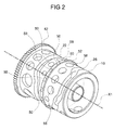
Figure 2 is a perspective view of the first drum of the gear control device ofFigure 1 . - With reference initially to
Figure 1 , a double-drum sequential gear control device for a motor-vehicle gearbox is generally indicated 100 and comprises basically: - a
first drum 10 rotatably mounted about a first rotation axis X1 which coincides with the geometrical axis of the drum and is arranged parallel to the axes of the gearbox shafts (not shown); - a first pair of
shift forks first drum 10 in order to bring about the movement of one or more engagement sleeves (not shown) slidably mounted on a first shaft of the gearbox, between respective neutral and engagement positions; - a
second drum 16 rotatably mounted about a second rotation axis X2 which coincides with the geometrical axis of the drum and is arranged parallel to the first rotation axis X1; - a second pair of
shift forks second drum 16 to bring about the movement of one or more engagement sleeves (not shown) slidably mounted on a second shaft of the gearbox, between respective neutral and engagement positions; and - an actuation unit (shown only partially) arranged to bring about rotation of the two
drums - In order to convert the rotary movements of the two drums about the respective rotation axes into translatory movements of the respective pairs of shift forks, the shift forks are connected for translation axially with respective pegs (or other follower members) which slidably engage in respective guide channels provided on the outer cylindrical surfaces of the drums. More specifically, the outer cylindrical surface of the
first drum 10 is provided with afirst guide channel 22 slidably engaged by afirst peg 24 which is connected for translation axially with theshift fork 12, and asecond guide channel 26 slidably engaged by asecond peg 28 which is connected for translation axially with theshift fork 14, and the outer cylindrical surface of thesecond drum 16 is provided with afirst guide channel 30 slidably engaged by afirst peg 32 which is connected for translation axially with theshift fork 18, and asecond guide channel 34 slidably engaged by asecond peg 36 which is connected for translation axially with theshift fork 20. Theshift forks first drum 10 are slidably mounted along astationary rod 38 supported by the housing (not shown) of the gearbox, but they could also be mounted so as to be fixed for translation with an axially slidable rod. Similarly, theshift forks second drum 16 are slidably mounted along astationary rod 40 supported by the housing, but they could also be mounted so as to be fixed for translation with an axially slidable rod. - The actuation unit comprises, basically, a motor (not shown), for example an electric motor, and a geared transmission mechanism which is arranged to transmit the rotary movement produced by the motor to the two drums and to synchronize the rotary movements of the two drums. More specifically, the geared transmission mechanism comprises a
first gear 42 which is arranged coaxially with thefirst drum 10 and is connected thereto so as to be fixed for rotation therewith, asecond gear 44 which is arranged coaxially with thesecond drum 16 and is connected thereto so as to be fixed for rotation therewith, a third gear 46 (hereinafter referred to as intermediate gear) permanently meshing with both of thegears gears 42 and 44 (in the present case, with the gear 44) through areduction gear 48 constituted for example by a double gear, but could also mesh directly with the gear 44 (or 42). The rotary movement imparted to the pinion by the motor is thus transmitted to thegear 44 of thesecond drum 16 and, through theintermediate gear 46, to thegear 42 of thefirst drum 10. The twodrums - With reference now also to
Figure 2 , in order to ensure that the engagement sleeves are held in position between one gear shift and the next irrespective of the presence of mechanical disturbances such as, for example, vibrations, thefirst drum 10 has a series of positioningnotches 50 which are arranged at predetermined angular distances from each other along a circumference of the drum. In the embodiment illustrated, thepositioning notches 50 are spaced at regular angular intervals but they could also be arranged at angular intervals that differ from one another. Naturally, eachpositioning notch 50 corresponds to a given angular position of thefirst drum 10 and hence to a given position of each of the engagement sleeves controlled by theshift forks positioning notches 50 are formed in anannular track 52 projecting radially from the outer cylindrical surface of thefirst drum 10. Thepositioning notches 50 are intended to be snap-engaged by astop member 54 which is formed, in the embodiment illustrated, as a detent pin. More precisely, thestop member 54 comprises aspherical pin 56 arranged radially relative to thefirst drum 10 and resilient means (not shown) acting on thespherical pin 56 so as to keep it urged against theannular track 52. Naturally, thestop member 54 will be positioned, relative to thefirst drum 10, in such a manner as to be aligned every time with one of thepositioning notches 50 when the drum is in an angular position corresponding to a stable engagement condition, that is to say, a condition in which all of the engagement sleeves are in the neutral position or in which one of the engagement sleeves is in the engagement position (or two engagement sleeves are in the engagement position in case of a gear control device applied to a double-clutch gearbox). When thefirst drum 10 is in an angular position corresponding to a stable engagement condition, thespherical pin 56 of thestop member 54 thus engages (and is kept in engagement by the respective resilient means) in one of thepositioning notches 50, thereby preventing the drum from rotating and moving away from the said angular position as a result of mechanical disturbances such as, for example, vibrations. When thefirst drum 10 is rotated by the motor of the actuation unit, on the other hand, thespherical pin 56 of thestop member 54 disengages from theprevious positioning notch 50 and slides along theannular track 52 until it engages in anew positioning notch 50 corresponding to a new angular position of the drum, that is, to a new stable engagement condition. - According to the invention, only one of the two drums has the positioning notches, since the angular positions of the two drums are univocally linked to one another. If the drum has two guide channels, preferably the positioning notches will be located axially between the guide channels, as clearly shown in the drawings.
- Moreover, preferably the drum has, on its outer cylindrical surface, a plurality of radial through-
holes 58 having a weight-reducing function. If the drum has two guide channels, advantageously two rings of radial through-holes will be provided and located each axially between the positioning notches and a respective guide channel. - Naturally, the principle of the invention remaining unchanged, the embodiments and details of construction may be varied widely with respect to those described and illustrated purely by way of non-limiting example.
Claims (6)
- A sequential gear control device (100) for a motor-vehicle gearbox, the gear control device comprising a first drum (10) and a second drum (16) each rotatable about a respective rotation axis (X1, X2) and an actuation unit (42, 44, 46, 48) arranged to bring about rotation of the first and second drums (10, 16) in a synchronized manner about the respective rotation axes, wherein each of said first and second drums (10, 16) has, on its outer cylindrical surface, at least one guide channel (22, 26) in which at least one follower member (24, 28) is intended to be guided slidably to convert the rotary movement of the drum (10, 16) about its own rotation axis (X1, X2) into translatory movement of at least one engagement sleeve of the gearbox, and wherein a series of positioning notches (50) are provided on the outer cylindrical surface of only the first drum (10) and are spaced apart angularly along a circumference of the first drum (50) for snap-engagement by a stop member (54, 56) of the gear control device (100) associated with the first drum (10).
- A gear control device according to claim 1, wherein the positioning notches (50) are formed in an annular track (52) projecting radially from the outer cylindrical surface of the first drum (10).
- A gear control device according to claim 1 or claim 2, wherein the positioning notches (50) are spaced apart at regular angular intervals.
- A gear control device according to any one of the preceding claims, wherein the first drum (10) has two guide channels (22, 26) and wherein the positioning notches (50) are located axially between the two guide channels (22, 26).
- A gear control device according to any one of the preceding claims, wherein the first drum (10) has a plurality of radial through-holes (58) on its outer cylindrical surface.
- A gear control device according to claims 4 and 5, wherein the first drum (10) has two rings of radial through-holes (58) each located axially between the positioning notches (50) and a respective guide channel (22, 26).
Priority Applications (1)
| Application Number | Priority Date | Filing Date | Title |
|---|---|---|---|
| EP11190035.3A EP2423538B1 (en) | 2010-06-03 | 2010-06-03 | A sequential gear control device for a motor-vehicle gearbox comprising a pair of rotary drums |
Applications Claiming Priority (2)
| Application Number | Priority Date | Filing Date | Title |
|---|---|---|---|
| EP10425188A EP2392841B1 (en) | 2010-06-03 | 2010-06-03 | Drum for a gear control device for a motor-vehicle gearbox and gear control device comprising such a drum |
| EP11190035.3A EP2423538B1 (en) | 2010-06-03 | 2010-06-03 | A sequential gear control device for a motor-vehicle gearbox comprising a pair of rotary drums |
Related Parent Applications (2)
| Application Number | Title | Priority Date | Filing Date |
|---|---|---|---|
| EP10425188A Division-Into EP2392841B1 (en) | 2010-06-03 | 2010-06-03 | Drum for a gear control device for a motor-vehicle gearbox and gear control device comprising such a drum |
| EP10425188.9 Division | 2010-06-03 |
Publications (2)
| Publication Number | Publication Date |
|---|---|
| EP2423538A1 true EP2423538A1 (en) | 2012-02-29 |
| EP2423538B1 EP2423538B1 (en) | 2013-09-18 |
Family
ID=42731927
Family Applications (2)
| Application Number | Title | Priority Date | Filing Date |
|---|---|---|---|
| EP10425188A Not-in-force EP2392841B1 (en) | 2010-06-03 | 2010-06-03 | Drum for a gear control device for a motor-vehicle gearbox and gear control device comprising such a drum |
| EP11190035.3A Not-in-force EP2423538B1 (en) | 2010-06-03 | 2010-06-03 | A sequential gear control device for a motor-vehicle gearbox comprising a pair of rotary drums |
Family Applications Before (1)
| Application Number | Title | Priority Date | Filing Date |
|---|---|---|---|
| EP10425188A Not-in-force EP2392841B1 (en) | 2010-06-03 | 2010-06-03 | Drum for a gear control device for a motor-vehicle gearbox and gear control device comprising such a drum |
Country Status (3)
| Country | Link |
|---|---|
| US (1) | US8596152B2 (en) |
| EP (2) | EP2392841B1 (en) |
| CN (1) | CN102269265B (en) |
Families Citing this family (9)
| Publication number | Priority date | Publication date | Assignee | Title |
|---|---|---|---|---|
| EP2549152B1 (en) * | 2011-07-20 | 2013-10-16 | C.R.F. Società Consortile per Azioni | Gear change device for a motor vehicle |
| TWI455749B (en) * | 2011-12-06 | 2014-10-11 | Univ Nat Taiwan Science Tech | Facial expression control device |
| DE102012004371A1 (en) * | 2012-03-02 | 2013-09-05 | Daimler Ag | Operating device for operating dual clutch gear box of motor car, has two shifting drums for shifting two sets of shifting elements, respectively, actuator for operating drums, and transfer case unit for coupling actuator with drums |
| DE102013220041A1 (en) * | 2012-10-24 | 2014-04-24 | Schaeffler Technologies Gmbh & Co. Kg | actuator |
| KR101637512B1 (en) * | 2015-03-24 | 2016-07-07 | 한국파워트레인 주식회사 | Gear actuator of Dual clutch transmission |
| JP5996701B1 (en) | 2015-03-30 | 2016-09-21 | 本田技研工業株式会社 | Transmission with synchro mechanism |
| DE102016201860A1 (en) * | 2016-02-08 | 2017-08-10 | Bayerische Motoren Werke Aktiengesellschaft | Device and method for locking a shift drum of a sequential gearbox |
| US11009127B2 (en) * | 2018-04-27 | 2021-05-18 | Kabushiki Kaisha Toyota Chuo Kenkyusho | Shift mechanism for power transmission device |
| DE102019219724B4 (en) * | 2019-12-16 | 2021-12-16 | Psa Automobiles Sa | Shifting a dual clutch transmission |
Citations (8)
| Publication number | Priority date | Publication date | Assignee | Title |
|---|---|---|---|---|
| GB791662A (en) * | 1955-06-23 | 1958-03-05 | David Brown And Sons Huddersfi | An improvement in or relating to selecting mechanism for variable-speed gearboxes |
| DE1202665B (en) * | 1962-11-27 | 1965-10-07 | Steyr Daimler Puch Ag | Switching device for motorcycle transmission |
| US4574652A (en) * | 1983-08-08 | 1986-03-11 | Honda Giken Kogyo Kabushiki Kaisha | Transmission for use in motor vehicles |
| EP1286088A1 (en) * | 2001-08-18 | 2003-02-26 | Getrag Ford Transmissions GmbH | Shifting arrangement for multiple ratio transmission |
| US20060162487A1 (en) * | 2005-01-25 | 2006-07-27 | Harley-Davidson Motor Company Group, Inc. | Composite shifter cam for a motorcycle transmission |
| US20070209461A1 (en) * | 2006-03-13 | 2007-09-13 | Reid Baldwin | Actuator mechanism for shift motors of a transmission |
| US20080081725A1 (en) * | 2006-09-29 | 2008-04-03 | Honda Motor Co., Ltd. | Vehicular transmission |
| WO2009090612A1 (en) * | 2008-01-16 | 2009-07-23 | Sila Holding Industriale S.P.A. | Gear shift control device for a vehicle gearbox with a rotating and axially floating drum |
Family Cites Families (9)
| Publication number | Priority date | Publication date | Assignee | Title |
|---|---|---|---|---|
| GB775728A (en) * | 1954-06-16 | 1957-05-29 | Nsu Werke Ag | Gear-changing device, more particularly a foot-operated gear-changing device for motor vehicles of any kind |
| DE19530616C2 (en) * | 1995-08-21 | 1998-10-22 | Daimler Benz Ag | Switching device for gear change transmission |
| DE19540522C1 (en) * | 1995-10-31 | 1997-02-20 | Porsche Ag | Gear selector system for vehicle |
| GB2330885A (en) * | 1997-11-01 | 1999-05-05 | David Benjamin Hirons | Gear change mechanism |
| DE10006721A1 (en) * | 2000-02-15 | 2001-08-16 | Schaeffler Waelzlager Ohg | Switching device of a change gearbox with damping element and switching path limitation |
| EP1182376B1 (en) * | 2000-08-22 | 2007-03-28 | GETRAG Getriebe- und Zahnradfabrik Hermann Hagenmeyer GmbH & Cie KG | Automated drive train for vehicle |
| US7428852B2 (en) * | 2006-03-13 | 2008-09-30 | Ford Global Technologies, Llc | Actuator mechanism for shift motors of a transmission |
| JP4698461B2 (en) * | 2006-03-28 | 2011-06-08 | 本田技研工業株式会社 | Shift drum device |
| ITTO20080034A1 (en) * | 2008-01-16 | 2009-07-17 | Automac Di Bigi Ing Maurizio Sas | CONTROL DEVICE FOR ENGAGEMENT OF GEARS FOR A SPEED CHANGE OF A VEHICLE WITH A ROTATING DRUM PRESENTING A MAIN CAM AND AN AUXILIARY CAM |
-
2010
- 2010-06-03 EP EP10425188A patent/EP2392841B1/en not_active Not-in-force
- 2010-06-03 EP EP11190035.3A patent/EP2423538B1/en not_active Not-in-force
- 2010-11-16 US US12/947,332 patent/US8596152B2/en not_active Expired - Fee Related
- 2010-11-23 CN CN201010559454.4A patent/CN102269265B/en not_active Expired - Fee Related
Patent Citations (8)
| Publication number | Priority date | Publication date | Assignee | Title |
|---|---|---|---|---|
| GB791662A (en) * | 1955-06-23 | 1958-03-05 | David Brown And Sons Huddersfi | An improvement in or relating to selecting mechanism for variable-speed gearboxes |
| DE1202665B (en) * | 1962-11-27 | 1965-10-07 | Steyr Daimler Puch Ag | Switching device for motorcycle transmission |
| US4574652A (en) * | 1983-08-08 | 1986-03-11 | Honda Giken Kogyo Kabushiki Kaisha | Transmission for use in motor vehicles |
| EP1286088A1 (en) * | 2001-08-18 | 2003-02-26 | Getrag Ford Transmissions GmbH | Shifting arrangement for multiple ratio transmission |
| US20060162487A1 (en) * | 2005-01-25 | 2006-07-27 | Harley-Davidson Motor Company Group, Inc. | Composite shifter cam for a motorcycle transmission |
| US20070209461A1 (en) * | 2006-03-13 | 2007-09-13 | Reid Baldwin | Actuator mechanism for shift motors of a transmission |
| US20080081725A1 (en) * | 2006-09-29 | 2008-04-03 | Honda Motor Co., Ltd. | Vehicular transmission |
| WO2009090612A1 (en) * | 2008-01-16 | 2009-07-23 | Sila Holding Industriale S.P.A. | Gear shift control device for a vehicle gearbox with a rotating and axially floating drum |
Also Published As
| Publication number | Publication date |
|---|---|
| CN102269265B (en) | 2014-10-29 |
| US8596152B2 (en) | 2013-12-03 |
| EP2392841B1 (en) | 2012-09-12 |
| EP2423538B1 (en) | 2013-09-18 |
| EP2392841A1 (en) | 2011-12-07 |
| CN102269265A (en) | 2011-12-07 |
| US20110296934A1 (en) | 2011-12-08 |
Similar Documents
| Publication | Publication Date | Title |
|---|---|---|
| EP2423538B1 (en) | A sequential gear control device for a motor-vehicle gearbox comprising a pair of rotary drums | |
| EP2385270B1 (en) | A hybrid propulsion system for a motor vehicle with a double-drum gear control device | |
| US10151359B2 (en) | Rotating multi-mode clutch module with stationary actuator | |
| US9482340B2 (en) | Shift arrangement for a motor vehicle transmission | |
| EP2143978B1 (en) | Sequential control device with rotating drum for engaging gears in a mechanical gearbox of a motor vehicle, particularly of a motor car | |
| US10260626B2 (en) | Cam mechanism for actuating a selector shaft | |
| EP2375101A3 (en) | Motor-vehicle double-clutch transmission with gear shift device comprising a rotary drum and motor-vehicle hybrid propulsion system including such a transmission | |
| JP5443766B2 (en) | Device for synchronous engagement of automotive gear transmissions | |
| CN104696509A (en) | Shift arrangement for a motor vehicle transmission and method for actuating said shift arrangement | |
| EP2247874B1 (en) | Gear shift control device for a vehicle gearbox provided with a rotating drum having a main cam and an auxiliary cam | |
| KR101512226B1 (en) | Shifting lever assembly using one shaft for agricultural machine | |
| KR101260050B1 (en) | Mission | |
| CN110513474B (en) | Switching device and transmission mechanism | |
| EP3559516A1 (en) | Gear shift arrangement for a transmission of a vehicle | |
| CN104913049B (en) | Speed changer | |
| KR20150009749A (en) | Rotating structure of weight for manual transmission | |
| US11339874B2 (en) | System for operation of a gearbox for a motor vehicle | |
| KR102001552B1 (en) | Shifting apparatus for dual clutch transmission | |
| GB2325714A (en) | Device for operating a selector shaft of a shift transmission | |
| KR101499936B1 (en) | Continuously Variable Transmission | |
| GB2526902A (en) | A gearbox | |
| CN102537324A (en) | Transmission shift device | |
| JP5064478B2 (en) | Transmission | |
| KR102388489B1 (en) | Apparatus and method for coupling, shifting and/or synchronization in a transmission | |
| JP6156119B2 (en) | Power transmission device assembly structure and power transmission device assembly method |
Legal Events
| Date | Code | Title | Description |
|---|---|---|---|
| AC | Divisional application: reference to earlier application |
Ref document number: 2392841 Country of ref document: EP Kind code of ref document: P |
|
| AK | Designated contracting states |
Kind code of ref document: A1 Designated state(s): AL AT BE BG CH CY CZ DE DK EE ES FI FR GB GR HR HU IE IS IT LI LT LU LV MC MK MT NL NO PL PT RO SE SI SK SM TR |
|
| AX | Request for extension of the european patent |
Extension state: BA ME RS |
|
| PUAI | Public reference made under article 153(3) epc to a published international application that has entered the european phase |
Free format text: ORIGINAL CODE: 0009012 |
|
| 17P | Request for examination filed |
Effective date: 20120827 |
|
| 17Q | First examination report despatched |
Effective date: 20121023 |
|
| GRAP | Despatch of communication of intention to grant a patent |
Free format text: ORIGINAL CODE: EPIDOSNIGR1 |
|
| INTG | Intention to grant announced |
Effective date: 20130412 |
|
| GRAS | Grant fee paid |
Free format text: ORIGINAL CODE: EPIDOSNIGR3 |
|
| GRAA | (expected) grant |
Free format text: ORIGINAL CODE: 0009210 |
|
| AC | Divisional application: reference to earlier application |
Ref document number: 2392841 Country of ref document: EP Kind code of ref document: P |
|
| AK | Designated contracting states |
Kind code of ref document: B1 Designated state(s): AL AT BE BG CH CY CZ DE DK EE ES FI FR GB GR HR HU IE IS IT LI LT LU LV MC MK MT NL NO PL PT RO SE SI SK SM TR |
|
| REG | Reference to a national code |
Ref country code: GB Ref legal event code: FG4D |
|
| REG | Reference to a national code |
Ref country code: CH Ref legal event code: EP |
|
| REG | Reference to a national code |
Ref country code: IE Ref legal event code: FG4D |
|
| REG | Reference to a national code |
Ref country code: AT Ref legal event code: REF Ref document number: 632972 Country of ref document: AT Kind code of ref document: T Effective date: 20131015 |
|
| REG | Reference to a national code |
Ref country code: DE Ref legal event code: R096 Ref document number: 602010010468 Country of ref document: DE Effective date: 20131107 |
|
| PG25 | Lapsed in a contracting state [announced via postgrant information from national office to epo] |
Ref country code: LT Free format text: LAPSE BECAUSE OF FAILURE TO SUBMIT A TRANSLATION OF THE DESCRIPTION OR TO PAY THE FEE WITHIN THE PRESCRIBED TIME-LIMIT Effective date: 20130918 Ref country code: SE Free format text: LAPSE BECAUSE OF FAILURE TO SUBMIT A TRANSLATION OF THE DESCRIPTION OR TO PAY THE FEE WITHIN THE PRESCRIBED TIME-LIMIT Effective date: 20130918 Ref country code: CY Free format text: LAPSE BECAUSE OF FAILURE TO SUBMIT A TRANSLATION OF THE DESCRIPTION OR TO PAY THE FEE WITHIN THE PRESCRIBED TIME-LIMIT Effective date: 20130814 Ref country code: NO Free format text: LAPSE BECAUSE OF FAILURE TO SUBMIT A TRANSLATION OF THE DESCRIPTION OR TO PAY THE FEE WITHIN THE PRESCRIBED TIME-LIMIT Effective date: 20131218 Ref country code: HR Free format text: LAPSE BECAUSE OF FAILURE TO SUBMIT A TRANSLATION OF THE DESCRIPTION OR TO PAY THE FEE WITHIN THE PRESCRIBED TIME-LIMIT Effective date: 20130918 |
|
| REG | Reference to a national code |
Ref country code: NL Ref legal event code: VDEP Effective date: 20130918 |
|
| REG | Reference to a national code |
Ref country code: AT Ref legal event code: MK05 Ref document number: 632972 Country of ref document: AT Kind code of ref document: T Effective date: 20130918 |
|
| REG | Reference to a national code |
Ref country code: LT Ref legal event code: MG4D |
|
| PG25 | Lapsed in a contracting state [announced via postgrant information from national office to epo] |
Ref country code: SI Free format text: LAPSE BECAUSE OF FAILURE TO SUBMIT A TRANSLATION OF THE DESCRIPTION OR TO PAY THE FEE WITHIN THE PRESCRIBED TIME-LIMIT Effective date: 20130918 Ref country code: FI Free format text: LAPSE BECAUSE OF FAILURE TO SUBMIT A TRANSLATION OF THE DESCRIPTION OR TO PAY THE FEE WITHIN THE PRESCRIBED TIME-LIMIT Effective date: 20130918 Ref country code: GR Free format text: LAPSE BECAUSE OF FAILURE TO SUBMIT A TRANSLATION OF THE DESCRIPTION OR TO PAY THE FEE WITHIN THE PRESCRIBED TIME-LIMIT Effective date: 20131219 Ref country code: LV Free format text: LAPSE BECAUSE OF FAILURE TO SUBMIT A TRANSLATION OF THE DESCRIPTION OR TO PAY THE FEE WITHIN THE PRESCRIBED TIME-LIMIT Effective date: 20130918 |
|
| PG25 | Lapsed in a contracting state [announced via postgrant information from national office to epo] |
Ref country code: CY Free format text: LAPSE BECAUSE OF FAILURE TO SUBMIT A TRANSLATION OF THE DESCRIPTION OR TO PAY THE FEE WITHIN THE PRESCRIBED TIME-LIMIT Effective date: 20130918 Ref country code: BE Free format text: LAPSE BECAUSE OF FAILURE TO SUBMIT A TRANSLATION OF THE DESCRIPTION OR TO PAY THE FEE WITHIN THE PRESCRIBED TIME-LIMIT Effective date: 20130918 |
|
| PG25 | Lapsed in a contracting state [announced via postgrant information from national office to epo] |
Ref country code: EE Free format text: LAPSE BECAUSE OF FAILURE TO SUBMIT A TRANSLATION OF THE DESCRIPTION OR TO PAY THE FEE WITHIN THE PRESCRIBED TIME-LIMIT Effective date: 20130918 Ref country code: SK Free format text: LAPSE BECAUSE OF FAILURE TO SUBMIT A TRANSLATION OF THE DESCRIPTION OR TO PAY THE FEE WITHIN THE PRESCRIBED TIME-LIMIT Effective date: 20130918 Ref country code: NL Free format text: LAPSE BECAUSE OF FAILURE TO SUBMIT A TRANSLATION OF THE DESCRIPTION OR TO PAY THE FEE WITHIN THE PRESCRIBED TIME-LIMIT Effective date: 20130918 Ref country code: CZ Free format text: LAPSE BECAUSE OF FAILURE TO SUBMIT A TRANSLATION OF THE DESCRIPTION OR TO PAY THE FEE WITHIN THE PRESCRIBED TIME-LIMIT Effective date: 20130918 Ref country code: IS Free format text: LAPSE BECAUSE OF FAILURE TO SUBMIT A TRANSLATION OF THE DESCRIPTION OR TO PAY THE FEE WITHIN THE PRESCRIBED TIME-LIMIT Effective date: 20140118 |
|
| PG25 | Lapsed in a contracting state [announced via postgrant information from national office to epo] |
Ref country code: AT Free format text: LAPSE BECAUSE OF FAILURE TO SUBMIT A TRANSLATION OF THE DESCRIPTION OR TO PAY THE FEE WITHIN THE PRESCRIBED TIME-LIMIT Effective date: 20130918 Ref country code: PL Free format text: LAPSE BECAUSE OF FAILURE TO SUBMIT A TRANSLATION OF THE DESCRIPTION OR TO PAY THE FEE WITHIN THE PRESCRIBED TIME-LIMIT Effective date: 20130918 Ref country code: ES Free format text: LAPSE BECAUSE OF FAILURE TO SUBMIT A TRANSLATION OF THE DESCRIPTION OR TO PAY THE FEE WITHIN THE PRESCRIBED TIME-LIMIT Effective date: 20130918 |
|
| REG | Reference to a national code |
Ref country code: DE Ref legal event code: R097 Ref document number: 602010010468 Country of ref document: DE |
|
| PG25 | Lapsed in a contracting state [announced via postgrant information from national office to epo] |
Ref country code: PT Free format text: LAPSE BECAUSE OF FAILURE TO SUBMIT A TRANSLATION OF THE DESCRIPTION OR TO PAY THE FEE WITHIN THE PRESCRIBED TIME-LIMIT Effective date: 20140120 |
|
| PLBE | No opposition filed within time limit |
Free format text: ORIGINAL CODE: 0009261 |
|
| STAA | Information on the status of an ep patent application or granted ep patent |
Free format text: STATUS: NO OPPOSITION FILED WITHIN TIME LIMIT |
|
| 26N | No opposition filed |
Effective date: 20140619 |
|
| PG25 | Lapsed in a contracting state [announced via postgrant information from national office to epo] |
Ref country code: DK Free format text: LAPSE BECAUSE OF FAILURE TO SUBMIT A TRANSLATION OF THE DESCRIPTION OR TO PAY THE FEE WITHIN THE PRESCRIBED TIME-LIMIT Effective date: 20130918 |
|
| REG | Reference to a national code |
Ref country code: DE Ref legal event code: R097 Ref document number: 602010010468 Country of ref document: DE Effective date: 20140619 |
|
| PG25 | Lapsed in a contracting state [announced via postgrant information from national office to epo] |
Ref country code: LU Free format text: LAPSE BECAUSE OF FAILURE TO SUBMIT A TRANSLATION OF THE DESCRIPTION OR TO PAY THE FEE WITHIN THE PRESCRIBED TIME-LIMIT Effective date: 20140603 Ref country code: MC Free format text: LAPSE BECAUSE OF FAILURE TO SUBMIT A TRANSLATION OF THE DESCRIPTION OR TO PAY THE FEE WITHIN THE PRESCRIBED TIME-LIMIT Effective date: 20130918 |
|
| REG | Reference to a national code |
Ref country code: CH Ref legal event code: PL |
|
| GBPC | Gb: european patent ceased through non-payment of renewal fee |
Effective date: 20140603 |
|
| REG | Reference to a national code |
Ref country code: IE Ref legal event code: MM4A |
|
| PG25 | Lapsed in a contracting state [announced via postgrant information from national office to epo] |
Ref country code: LI Free format text: LAPSE BECAUSE OF NON-PAYMENT OF DUE FEES Effective date: 20140630 Ref country code: CH Free format text: LAPSE BECAUSE OF NON-PAYMENT OF DUE FEES Effective date: 20140630 Ref country code: IE Free format text: LAPSE BECAUSE OF NON-PAYMENT OF DUE FEES Effective date: 20140603 |
|
| PG25 | Lapsed in a contracting state [announced via postgrant information from national office to epo] |
Ref country code: GB Free format text: LAPSE BECAUSE OF NON-PAYMENT OF DUE FEES Effective date: 20140603 |
|
| PG25 | Lapsed in a contracting state [announced via postgrant information from national office to epo] |
Ref country code: MT Free format text: LAPSE BECAUSE OF FAILURE TO SUBMIT A TRANSLATION OF THE DESCRIPTION OR TO PAY THE FEE WITHIN THE PRESCRIBED TIME-LIMIT Effective date: 20130918 |
|
| PG25 | Lapsed in a contracting state [announced via postgrant information from national office to epo] |
Ref country code: SM Free format text: LAPSE BECAUSE OF FAILURE TO SUBMIT A TRANSLATION OF THE DESCRIPTION OR TO PAY THE FEE WITHIN THE PRESCRIBED TIME-LIMIT Effective date: 20130918 |
|
| PG25 | Lapsed in a contracting state [announced via postgrant information from national office to epo] |
Ref country code: RO Free format text: LAPSE BECAUSE OF FAILURE TO SUBMIT A TRANSLATION OF THE DESCRIPTION OR TO PAY THE FEE WITHIN THE PRESCRIBED TIME-LIMIT Effective date: 20130918 |
|
| REG | Reference to a national code |
Ref country code: FR Ref legal event code: PLFP Year of fee payment: 7 |
|
| PG25 | Lapsed in a contracting state [announced via postgrant information from national office to epo] |
Ref country code: BG Free format text: LAPSE BECAUSE OF FAILURE TO SUBMIT A TRANSLATION OF THE DESCRIPTION OR TO PAY THE FEE WITHIN THE PRESCRIBED TIME-LIMIT Effective date: 20130918 |
|
| PG25 | Lapsed in a contracting state [announced via postgrant information from national office to epo] |
Ref country code: TR Free format text: LAPSE BECAUSE OF FAILURE TO SUBMIT A TRANSLATION OF THE DESCRIPTION OR TO PAY THE FEE WITHIN THE PRESCRIBED TIME-LIMIT Effective date: 20130918 Ref country code: HU Free format text: LAPSE BECAUSE OF FAILURE TO SUBMIT A TRANSLATION OF THE DESCRIPTION OR TO PAY THE FEE WITHIN THE PRESCRIBED TIME-LIMIT; INVALID AB INITIO Effective date: 20100603 |
|
| REG | Reference to a national code |
Ref country code: FR Ref legal event code: PLFP Year of fee payment: 8 |
|
| PG25 | Lapsed in a contracting state [announced via postgrant information from national office to epo] |
Ref country code: MK Free format text: LAPSE BECAUSE OF FAILURE TO SUBMIT A TRANSLATION OF THE DESCRIPTION OR TO PAY THE FEE WITHIN THE PRESCRIBED TIME-LIMIT Effective date: 20130918 |
|
| REG | Reference to a national code |
Ref country code: FR Ref legal event code: PLFP Year of fee payment: 9 |
|
| PG25 | Lapsed in a contracting state [announced via postgrant information from national office to epo] |
Ref country code: AL Free format text: LAPSE BECAUSE OF FAILURE TO SUBMIT A TRANSLATION OF THE DESCRIPTION OR TO PAY THE FEE WITHIN THE PRESCRIBED TIME-LIMIT Effective date: 20130918 |
|
| PGFP | Annual fee paid to national office [announced via postgrant information from national office to epo] |
Ref country code: FR Payment date: 20210630 Year of fee payment: 12 Ref country code: IT Payment date: 20210608 Year of fee payment: 12 Ref country code: DE Payment date: 20210618 Year of fee payment: 12 |
|
| REG | Reference to a national code |
Ref country code: DE Ref legal event code: R119 Ref document number: 602010010468 Country of ref document: DE |
|
| PG25 | Lapsed in a contracting state [announced via postgrant information from national office to epo] |
Ref country code: FR Free format text: LAPSE BECAUSE OF NON-PAYMENT OF DUE FEES Effective date: 20220630 |
|
| PG25 | Lapsed in a contracting state [announced via postgrant information from national office to epo] |
Ref country code: DE Free format text: LAPSE BECAUSE OF NON-PAYMENT OF DUE FEES Effective date: 20230103 |
|
| PG25 | Lapsed in a contracting state [announced via postgrant information from national office to epo] |
Ref country code: IT Free format text: LAPSE BECAUSE OF NON-PAYMENT OF DUE FEES Effective date: 20220603 |