EP2423469A2 - Combined power augmentation system and method - Google Patents
Combined power augmentation system and method Download PDFInfo
- Publication number
- EP2423469A2 EP2423469A2 EP10150685A EP10150685A EP2423469A2 EP 2423469 A2 EP2423469 A2 EP 2423469A2 EP 10150685 A EP10150685 A EP 10150685A EP 10150685 A EP10150685 A EP 10150685A EP 2423469 A2 EP2423469 A2 EP 2423469A2
- Authority
- EP
- European Patent Office
- Prior art keywords
- heater
- output
- pressure super
- super
- high pressure
- Prior art date
- Legal status (The legal status is an assumption and is not a legal conclusion. Google has not performed a legal analysis and makes no representation as to the accuracy of the status listed.)
- Withdrawn
Links
- 238000000034 method Methods 0.000 title claims description 15
- 230000003416 augmentation Effects 0.000 title 1
- 230000000153 supplemental effect Effects 0.000 claims abstract description 49
- 238000011084 recovery Methods 0.000 claims abstract description 33
- XLYOFNOQVPJJNP-UHFFFAOYSA-N water Substances O XLYOFNOQVPJJNP-UHFFFAOYSA-N 0.000 claims description 21
- 239000003054 catalyst Substances 0.000 claims description 14
- 238000010248 power generation Methods 0.000 claims description 11
- 238000010531 catalytic reduction reaction Methods 0.000 claims description 7
- 239000007789 gas Substances 0.000 description 79
- 239000000446 fuel Substances 0.000 description 8
- 238000002485 combustion reaction Methods 0.000 description 6
- 230000005611 electricity Effects 0.000 description 5
- 239000000284 extract Substances 0.000 description 5
- QGZKDVFQNNGYKY-UHFFFAOYSA-N Ammonia Chemical compound N QGZKDVFQNNGYKY-UHFFFAOYSA-N 0.000 description 4
- 238000010586 diagram Methods 0.000 description 4
- VNWKTOKETHGBQD-UHFFFAOYSA-N methane Chemical compound C VNWKTOKETHGBQD-UHFFFAOYSA-N 0.000 description 4
- 239000000295 fuel oil Substances 0.000 description 3
- 238000002347 injection Methods 0.000 description 3
- 239000007924 injection Substances 0.000 description 3
- 239000000243 solution Substances 0.000 description 3
- 229910021529 ammonia Inorganic materials 0.000 description 2
- 238000001816 cooling Methods 0.000 description 2
- 238000010438 heat treatment Methods 0.000 description 2
- 239000003345 natural gas Substances 0.000 description 2
- 238000011144 upstream manufacturing Methods 0.000 description 2
- 239000002028 Biomass Substances 0.000 description 1
- 230000004075 alteration Effects 0.000 description 1
- QVGXLLKOCUKJST-UHFFFAOYSA-N atomic oxygen Chemical compound [O] QVGXLLKOCUKJST-UHFFFAOYSA-N 0.000 description 1
- 238000006243 chemical reaction Methods 0.000 description 1
- 239000003245 coal Substances 0.000 description 1
- 239000002283 diesel fuel Substances 0.000 description 1
- 239000007788 liquid Substances 0.000 description 1
- 238000004519 manufacturing process Methods 0.000 description 1
- 239000001301 oxygen Substances 0.000 description 1
- 229910052760 oxygen Inorganic materials 0.000 description 1
- 239000003208 petroleum Substances 0.000 description 1
- 238000006722 reduction reaction Methods 0.000 description 1
- 238000006467 substitution reaction Methods 0.000 description 1
- 239000002918 waste heat Substances 0.000 description 1
- 239000002699 waste material Substances 0.000 description 1
Images


Classifications
-
- F—MECHANICAL ENGINEERING; LIGHTING; HEATING; WEAPONS; BLASTING
- F02—COMBUSTION ENGINES; HOT-GAS OR COMBUSTION-PRODUCT ENGINE PLANTS
- F02C—GAS-TURBINE PLANTS; AIR INTAKES FOR JET-PROPULSION PLANTS; CONTROLLING FUEL SUPPLY IN AIR-BREATHING JET-PROPULSION PLANTS
- F02C6/00—Plural gas-turbine plants; Combinations of gas-turbine plants with other apparatus; Adaptations of gas-turbine plants for special use
- F02C6/18—Plural gas-turbine plants; Combinations of gas-turbine plants with other apparatus; Adaptations of gas-turbine plants for special use using the waste heat of gas-turbine plants outside the plants themselves, e.g. gas-turbine power heat plants
-
- F—MECHANICAL ENGINEERING; LIGHTING; HEATING; WEAPONS; BLASTING
- F01—MACHINES OR ENGINES IN GENERAL; ENGINE PLANTS IN GENERAL; STEAM ENGINES
- F01K—STEAM ENGINE PLANTS; STEAM ACCUMULATORS; ENGINE PLANTS NOT OTHERWISE PROVIDED FOR; ENGINES USING SPECIAL WORKING FLUIDS OR CYCLES
- F01K23/00—Plants characterised by more than one engine delivering power external to the plant, the engines being driven by different fluids
- F01K23/02—Plants characterised by more than one engine delivering power external to the plant, the engines being driven by different fluids the engine cycles being thermally coupled
- F01K23/06—Plants characterised by more than one engine delivering power external to the plant, the engines being driven by different fluids the engine cycles being thermally coupled combustion heat from one cycle heating the fluid in another cycle
- F01K23/10—Plants characterised by more than one engine delivering power external to the plant, the engines being driven by different fluids the engine cycles being thermally coupled combustion heat from one cycle heating the fluid in another cycle with exhaust fluid of one cycle heating the fluid in another cycle
-
- F—MECHANICAL ENGINEERING; LIGHTING; HEATING; WEAPONS; BLASTING
- F02—COMBUSTION ENGINES; HOT-GAS OR COMBUSTION-PRODUCT ENGINE PLANTS
- F02C—GAS-TURBINE PLANTS; AIR INTAKES FOR JET-PROPULSION PLANTS; CONTROLLING FUEL SUPPLY IN AIR-BREATHING JET-PROPULSION PLANTS
- F02C6/00—Plural gas-turbine plants; Combinations of gas-turbine plants with other apparatus; Adaptations of gas-turbine plants for special use
-
- F—MECHANICAL ENGINEERING; LIGHTING; HEATING; WEAPONS; BLASTING
- F05—INDEXING SCHEMES RELATING TO ENGINES OR PUMPS IN VARIOUS SUBCLASSES OF CLASSES F01-F04
- F05D—INDEXING SCHEME FOR ASPECTS RELATING TO NON-POSITIVE-DISPLACEMENT MACHINES OR ENGINES, GAS-TURBINES OR JET-PROPULSION PLANTS
- F05D2240/00—Components
- F05D2240/40—Use of a multiplicity of similar components
-
- Y—GENERAL TAGGING OF NEW TECHNOLOGICAL DEVELOPMENTS; GENERAL TAGGING OF CROSS-SECTIONAL TECHNOLOGIES SPANNING OVER SEVERAL SECTIONS OF THE IPC; TECHNICAL SUBJECTS COVERED BY FORMER USPC CROSS-REFERENCE ART COLLECTIONS [XRACs] AND DIGESTS
- Y02—TECHNOLOGIES OR APPLICATIONS FOR MITIGATION OR ADAPTATION AGAINST CLIMATE CHANGE
- Y02E—REDUCTION OF GREENHOUSE GAS [GHG] EMISSIONS, RELATED TO ENERGY GENERATION, TRANSMISSION OR DISTRIBUTION
- Y02E20/00—Combustion technologies with mitigation potential
- Y02E20/14—Combined heat and power generation [CHP]
-
- Y—GENERAL TAGGING OF NEW TECHNOLOGICAL DEVELOPMENTS; GENERAL TAGGING OF CROSS-SECTIONAL TECHNOLOGIES SPANNING OVER SEVERAL SECTIONS OF THE IPC; TECHNICAL SUBJECTS COVERED BY FORMER USPC CROSS-REFERENCE ART COLLECTIONS [XRACs] AND DIGESTS
- Y02—TECHNOLOGIES OR APPLICATIONS FOR MITIGATION OR ADAPTATION AGAINST CLIMATE CHANGE
- Y02E—REDUCTION OF GREENHOUSE GAS [GHG] EMISSIONS, RELATED TO ENERGY GENERATION, TRANSMISSION OR DISTRIBUTION
- Y02E20/00—Combustion technologies with mitigation potential
- Y02E20/16—Combined cycle power plant [CCPP], or combined cycle gas turbine [CCGT]
-
- Y—GENERAL TAGGING OF NEW TECHNOLOGICAL DEVELOPMENTS; GENERAL TAGGING OF CROSS-SECTIONAL TECHNOLOGIES SPANNING OVER SEVERAL SECTIONS OF THE IPC; TECHNICAL SUBJECTS COVERED BY FORMER USPC CROSS-REFERENCE ART COLLECTIONS [XRACs] AND DIGESTS
- Y02—TECHNOLOGIES OR APPLICATIONS FOR MITIGATION OR ADAPTATION AGAINST CLIMATE CHANGE
- Y02P—CLIMATE CHANGE MITIGATION TECHNOLOGIES IN THE PRODUCTION OR PROCESSING OF GOODS
- Y02P80/00—Climate change mitigation technologies for sector-wide applications
- Y02P80/10—Efficient use of energy, e.g. using compressed air or pressurized fluid as energy carrier
- Y02P80/15—On-site combined power, heat or cool generation or distribution, e.g. combined heat and power [CHP] supply
Definitions
- the subject matter disclosed herein relates to producing electrical power and, in particular, to producing electrical power during peak demand periods by utilizing peaker cycle heat exhaust recovery.
- Baseload (also base load, or baseload demand) is the minimum amount of power that a utility or distribution company must make available to its customers, or the amount of power required to meet minimum demands based on reasonable expectations of customer requirements. Baseload values typically vary from hour to hour in most commercial and industrial areas. The baseload is generated by a so-called “baseload power plant.”
- Peaks or spikes in customer power demand are handled by smaller and more responsive types of power plants called peaker power plants.
- a baseload power plant may be co-located with a peaker power plant.
- the time that a peaker plant operates may be many hours a day or as little as a few hours per year, depending on the condition of the region's electrical grid. It is expensive to build an efficient power plant, so if a peaker plant is only going to be run for a short or highly variable time, it may not make economic sense to make it as efficient as a base load power plant.
- the equipment and fuels used in base load plants are often unsuitable for use in peaker plants because the fluctuating conditions would severely strain the equipment. For these reasons, nuclear, geothermal, waste-to-energy, coal, and biomass plants are rarely, if ever, operated as peaker plants.
- Peaker plants are generally gas turbines that bum natural gas. A few burn petroleum-derived liquids, such as diesel oil and jet fuel, but they are usually more expensive than natural gas, so their use is limited.
- HRSG Heat Recovery Steam Generator
- Peak load requirements in the past have been met using different techniques depending on the duration and the maximum power requirements. Some are described below.
- an electrical power generation system includes a first gas turbine and a heat recovery steam generator coupled to the gas turbine.
- the heat recovery steam generator includes a high pressure super-heater having a high pressure super-heater output.
- the system also includes a second gas turbine and an output duct coupled to the second gas turbine.
- the system also includes a supplemental high pressure super-heater within the output duct and thermally coupled to the high pressure super-heater output and an attemperator coupled between the high pressure super-heater output and the supplemental high pressure super-heater.
- an electrical power generation system includes a combined cycle and a peaker cycle.
- the combined cycle includes a gas turbine and a heat recovery steam generator coupled to the gas turbine.
- the heat recovery steam generator includes an intermediate pressure super-heater having an intermediate pressure super-heater output and a low pressure super-heater having a low pressure super-heater output.
- the peaker cycle includes a peaker gas turbine and an output duct coupled to the peaker gas turbine.
- the peaker cycle also includes a supplemental intermediate pressure super-heater within the output duct and thermally coupled to the high pressure super-heater output and a supplemental low pressure super-heater within the output duct and thermally coupled to the low pressure super-heater output.
- a method for operating a system including a combined cycle and a peaker cycle, the combined cycle including a gas turbine and a heat recovery steam generator coupled to the gas turbine and a peaker cycle including a peaker gas turbine and an output duct.
- the method includes superheating a high pressure output product in the heat recovery steam generator; superheating the output product in a supplemental high pressure super-heater within the output duct after the output product has be superheated in the heat recovery steam generator and before the output product is provided a another turbine; and mixing the output product with water in an attemperator before the output product is superheated in the supplemental high pressure super-heater.
- FIG. 1 shows an example of an electrical power generation system 100 according to one embodiment of the present invention.
- the system 100 includes combined cycle 102 and a peaker cycle 104.
- the combined cycle 102 may include a compressor 106 that includes an air intake 107.
- the compressor 106 is coupled to a combustor 108 that combusts a gas or fuel oil in a stream of compressed air.
- the compressor 108 is coupled to a gas turbine 110.
- the gas turbine 110 extracts energy from a flow of hot gas produced by combustion of gas or fuel. In one embodiment, the extracted engery is converted to electricity.
- the output 112 of the gas turbine 110 is an exhaust gas that may be used in other cycles of the combined system 100.
- the exhaust gas may be used, for example, to heat steam for use in a steam turbine (not shown).
- the combined cycle thus, includes an HSRG 114.
- the HSRG 114 may include a high pressure super-heater 116, an intermediate pressure super-heater 118 and a low pressure super-heater 120.
- the HSRG 114 may include only the low pressure super-heater 120 or any combination of the low pressure super-heater 120 and another super-heater.
- the exhaust gas may be at a temperature of appoximately 1150 °F.
- the exhaust gas is processed in an exhaust duct 120 which includes a low temperature SCR 124 to treat the exhaust gas before it is released through the stack 126.
- the system 100 also includes a peaker cycle 104.
- peaker cycle 104 In the prior art, such systems, however, had low peak load efficiency. One cause for this low efficiency may be due to un-recovered heat from exhaust gas in the peaker cycle.
- these systems required the utilization of less reliable and expensive high temperature SCR catalysts and an additional external high cost cooling fan to cool the exhaust gas to high temperature SCR levels. Further, such systems typically required an external skid for an ammonia injection system to effectively operate a high temperature SCR.
- the peaker cycle 104 includes a peaker gas turbine 130.
- the peaker gas turbine 130 is coupled to a peaker compressor 132 by a peaker combustor 134.
- the output temperature of the peaker exhaust gas 140 is about 1150 °F and is passed through a peaker exhaust duct 142.
- the peaker exhaust duct 142 includes a low pressure supplementary super-heater 136 and a peaker low-temperature SCR 138.
- the peaker HSRG 142 may be coupled to the stack 126.
- An output of the low pressure super-heater 114 is coupled to an input of the supplementary low presssure super-heater 136.
- An input of the low pressure super-heater may be coupled to a low pressure condensor (not shown).
- the temperature of the output product (typically steam) of the low pressure super-heater 114 is typically about 600 °F.
- the cooling of the peaker gas turbine's 130 exhaust gas to this temperature allows for normal, rather than high temperature, SCR to be performed thereon.
- the waste heat from the peaker cycle 104 has been recovered and, thus, the net efficiency of the combined cycle and peaker cycle is improved.
- the output of the supplemental low pressure super-heater 136 is provided to a low pressure turbine inlet nozzle.
- the output of the supplemental low pressure super-heater 136 may be diverted to different stages of the low pressure turbine as taught, for example, in U.S. Patent No. 6,442,924 .
- FIG. 2 shows an example of an electrical power generation system 200 similar to that shown in FIG. 1 with an optional low pressure water flow 202.
- the optional low pressure water flow 202 includes a water pump 204 and a low pressure steam attemperator 206.
- the optional additional water flow 202 may serve to reduce the temperature of the output product before introduction into a low pressure turbine.
- the temperature of the output product entering the low pressure steam attemperator 206 may be about 1050 °F and leave at a temperature of about 700-800 °F.
- exhaust gas from the peaker turbine is used to superheat low pressure steam for later use by a combined cycle system and, thereby, increases the efficiency of the combined cycle system.
- intermediate and high pressure steam temperatures for a typical combined cycle plant are about 1050 °F. This makes any additional super heating of these steams using peaker exhaust heat impossible.
- high pressure steam from the combined cycle is attemperated from about 1050 °F down to about 650 °F before allowing it to pass through the supplementary high pressure super-heater section in the peaker cycle exhaust path. This enables the peaker cycle exhaust heat (temperature about 1150 °F) recovery using high-pressure steam that has high heat-work conversion efficiency.
- optional LP steam circuit from the combined cycle is also used to reduce the exhaust heat to lowest possible temperature. Overall, this embodiment may enable additional power output gain of 50 MW during peaker cycle operation, compared to 35 MW gain from previous designs. Further, the temperature levels upstream of the catalyst can be maintained as low as required for a combined cycle catalyst to ensure efficient operation of the catalyst.
- FIG. 3 shows a system 300 according to another embodiment of the present invention.
- the system includes a peaker cycle 302.
- the remainder of the system 300 not included in the peaker cycle 302 shall be referred to herein as a combined cycle.
- the peaker cycle 302 includes a compressor 303, a combustor 304 and a gas turbine 306. As discussed above, the gas turbine 306 extracts energy from a flow of hot gas produced by combustion of gas or fuel. In one embodiment, the extracted engery is converted to electricity.
- the peaker cycle 302, also includes an output duct 308.
- the output duct 308 processes exhaust gas from the gas turbine 306 before it is expelled to the environment. The processing of the exhaust may be accomplished by SCR 314. In one emboidment, the SCR 314 utilizes normal, rather than high, temperature catalysts.
- the output duct 308 also includes a supplemental low pressure super-heater 310 and a supplemental high pressure super-heater 312.
- the supplemental super-heaters 310 and 312 are, respectively, connected to the output of a low pressure super-heater 316 and a high pressure super-heater contained in the combined cycle.
- the combined cycle may include a compressor 320 that includes an air intake 321.
- the compressor 320 is coupled to a combustor 322 that combusts a gas or fuel oil in a stream of compressed air.
- the compressor 322 is coupled to a gas turbine 324.
- the gas turbine 324 extracts energy from a flow of hot gas produced by combustion of gas or fuel. In one embodiment, the extracted energy is converted to electricity.
- the output of the gas turbine 324 is an exhaust gas that may be used in other cycles of the combined system.
- the exhaust gas may be used, for example, to heat steam for use in a high pressure steam turbine 326 and a low pressure steam turbine 328.
- the combined cycle includes an HSRG 330.
- the HSRG 330 may include a low pressure super-heater 316 and high pressure super-heater 318.
- Steam passing through the high pressure super-heater 318 exits at temperature of about 1050 °F.
- the steam is mixed with water by the high pressure pre-attemperator 332.
- the steam leaves the high pressure pre-attemperator 332 at a temperature of about 650 °F.
- the high pressure pre-attemperator 332 receives the steam from an output of the high pressure super-heater 318 and water from a first pump 336.
- the low pressure pre-attemperator 334 receives the steam from an output of the low pressure super-heater 316 and water from a second pump 338.
- the super-heaters 316 and 318 receive water from a third pump 339.
- the output of both the high pressure pre-attemperator 332 and the low pressure pre-attemperator 334 are then superheated in the output duct 308 of the peaker cycle 302.
- the output of the high pressure pre-attemperator 332 is connected to an input of the supplementary high pressure super-heater 312.
- the output of the high pressure pre-attemperator 332 is superheated to a temperature of about 1050 °F by the supplementary high pressure super-heater 312.
- the output of the supplementary high pressure super-heater 312 is coupled to an input of a high/intermediate pressure steam turbine 340.
- the output of the low pressure pre-attemperator 334 is connected to an input of the supplementary low pressure super-heater 310.
- the output of the low pressure pre-attemperator 334 is superheated to a temperature of about 600 °F by the supplementary low pressure super-heater 310.
- the output of the supplementary low pressure super-heater 310 is coupled to an input of a low pressure steam turbine 342. Remaining steam from the high/intermediate pressure steam turbine 340 and the low pressure steam turbine 342 is condensed in the condensor 344 and the water produced therein is provided to the pumps 336, 338 and 339.
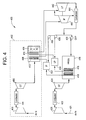
- FIG. 4 shows a system 400 according to another embodiment of the present invention.
- the system includes a peaker cycle 402.
- the remainder of the system 400 not included in the peaker cycle 402 shall be referred to herein as a combined cycle.
- the peaker cycle 402 includes a compressor 403, a combustor 404 and a gas turbine 406. As discussed above, the gas turbine 406 extracts energy from a flow of hot gas produced by combustion of gas or fuel. In one embodiment, the extracted engery is converted to electricity.
- the peaker cycle 402 also includes an output duct 408.
- the output duct 408 processes exhaust gas from the gas turbine 406 before it is expelled to the environment. The processing of the exhaust may be accomplished by SCR 414. In one emboidment, the SCR 414 utilizes normal, rather than high, temperature catalysts.
- the output duct 408 also includes a supplemental low pressure super-heater 410 and a supplemental intermediate pressure super-heater 412.
- the supplemental super-heaters 410 and 412 are, respectively, connected to the output of a low pressure super-heater 416 and a intermediate pressure super-heater 418 contained in the combined cycle.
- the combined cycle may include a compressor 420 that includes an air intake 421.
- the compressor 420 is coupled to a combustor 422 that combusts a gas or fuel oil in a stream of compressed air.
- the compressor 422 is coupled to a gas turbine 424.
- the gas turbine 424 extracts energy from a flow of hot gas produced by combustion of gas or fuel. In one embodiment, the extracted engery is converted to electricity.
- the output of the gas turbine 424 is an exhaust gas that may be used in other cycles of the combined system.
- the exhaust gas may be used, for example, to heat steam for use in an intermediate pressure steam turbine 426 and a low pressure steam turbine 428.
- the combined cycle includes an HSRG 430.
- the HSRG 430 may includes a low pressure super-heater 416 and an intermediate pressure super-heater 418.
- the intermediate pressure pre-attemperator 432 receives the steam from an output of the intermediate pressure super-heater 418 and water from a first pump 436.
- the low pressure pre-attemperator 434 receives the steam from an output of the low pressure super-heater 416 and water from a second pump 438.
- the super-heaters 416 and 418 receive water from a third pump 439.
- the output of both the intermediate pressure pre-attemperator 432 and the low pressure pre-attemperator 434 are then superheated in the output duct 408 of the peaker cycle 402.
- the output of the intermediate pressure pre-attemperator 432 is connected to an input of the supplementary intermediate pressure super-heater 412.
- the output of the intermediate pressure pre-attemperator 432 is superheated to a temperature of about 1050 °F by the supplementary intermediate pressure super-heater 412.
- the output of the supplementary intermediate pressure super-heater 412 is coupled to an input of a intermediate pressure steam turbine 440.
- the output of the low pressure pre-attemperator 434 is connected to an input of the supplementary low pressure super-heater 410.
- the output of the low pressure pre-attemperator 434 is superheated to a temperature of about 600 °F by the supplementary low pressure super-heater 410.
- the output of the supplementary low pressure super-heater 410 is coupled to an input of a low pressure steam turbine 442. Remaining steam from the intermediate pressure steam turbine 440 and the low pressure steam turbine 442 is condensed in the condensor 444 and the water produced therein is provided to the pumps 436, 438 and 439.
Landscapes
- Engineering & Computer Science (AREA)
- Chemical & Material Sciences (AREA)
- Combustion & Propulsion (AREA)
- Mechanical Engineering (AREA)
- General Engineering & Computer Science (AREA)
- Engine Equipment That Uses Special Cycles (AREA)
- Control Of Eletrric Generators (AREA)
- Connection Of Motors, Electrical Generators, Mechanical Devices, And The Like (AREA)
Abstract
An electrical generation system including a first gas turbine (324) and a heat recovery steam generator (330) coupled to the gas turbine and including high pressure super-heater (318) having a high pressure super-heater output. The electrical generation system also includes a second gas turbine (306), an output duct (308) coupled to the second gas turbine and a supplemental high pressure super-heater (312) within the output duct and thermally coupled to the high pressure super-heater output.
Description
- The subject matter disclosed herein relates to producing electrical power and, in particular, to producing electrical power during peak demand periods by utilizing peaker cycle heat exhaust recovery.
- Baseload (also base load, or baseload demand) is the minimum amount of power that a utility or distribution company must make available to its customers, or the amount of power required to meet minimum demands based on reasonable expectations of customer requirements. Baseload values typically vary from hour to hour in most commercial and industrial areas. The baseload is generated by a so-called "baseload power plant."
- Peaks or spikes in customer power demand are handled by smaller and more responsive types of power plants called peaker power plants. Of course, a baseload power plant may be co-located with a peaker power plant. The time that a peaker plant operates may be many hours a day or as little as a few hours per year, depending on the condition of the region's electrical grid. It is expensive to build an efficient power plant, so if a peaker plant is only going to be run for a short or highly variable time, it may not make economic sense to make it as efficient as a base load power plant. In addition, the equipment and fuels used in base load plants are often unsuitable for use in peaker plants because the fluctuating conditions would severely strain the equipment. For these reasons, nuclear, geothermal, waste-to-energy, coal, and biomass plants are rarely, if ever, operated as peaker plants.
- Peaker plants are generally gas turbines that bum natural gas. A few burn petroleum-derived liquids, such as diesel oil and jet fuel, but they are usually more expensive than natural gas, so their use is limited.
- For greater efficiency, a Heat Recovery Steam Generator (HRSG) is added at the exhaust. This is known as a combined cycle plant. Cogeneration uses waste exhaust heat for process or other heating uses. Both of these options are used only in plants that are intended to be operated for longer periods than usual.
- Peak load requirements in the past have been met using different techniques depending on the duration and the maximum power requirements. Some are described below.
- One prior solution is the so-called "duct burning" solution. During the peak load operation, additional fuel is burned in the exhaust stack upstream of a heat recovery steam generator (HRSG) to produce additional heat and hence additional steam flow and concomitant power output in the bottoming cycle. The exhaust gas is oxygen depleted and, thus, the combustion is not highly efficient. Further the non-uniform temperature distribution may lead to HRSG tube life reduction. In addition, the turbines operate slightly in "off-design" conditions to account for more flow during the peak load operation, making the normal combined cycle mode operation less efficient and lower yielding.
- Another solution involves utilizing a simple cycle gas turbine. For applications requiring high peak loads over significantly long periods of time, supplementary simple cycle based gas turbines are used. Start-up time for such turbines must be short, ranging from 7 - 10 minutes, and it is an important design requirement. Such systems may operate with operating efficiency of about 37% and power output of 175 MW, for example. Such systems, however, may have low peak load efficiency due to un-recovered heat in their exhaust. In addition, these systems may require expensive and less reliable high temperature selective catalytic reduction (SCR) catalysts to reduce peaker cycle NOx production. Further, exhaust fans for high temperature SCR are very expensive and themselves impose a high auxilary demand power penalty. In cases where an ammonia injection system is used in a peaker system, the external skids for the ammunia injection system is very high.
- According to one aspect of the invention, an electrical power generation system is provided. The system includes a first gas turbine and a heat recovery steam generator coupled to the gas turbine. The heat recovery steam generator includes a high pressure super-heater having a high pressure super-heater output. The system also includes a second gas turbine and an output duct coupled to the second gas turbine. The system also includes a supplemental high pressure super-heater within the output duct and thermally coupled to the high pressure super-heater output and an attemperator coupled between the high pressure super-heater output and the supplemental high pressure super-heater.
- According to one aspect of the invention, an electrical power generation system is provided. The system of this aspect includes a combined cycle and a peaker cycle. The combined cycle includes a gas turbine and a heat recovery steam generator coupled to the gas turbine. The heat recovery steam generator includes an intermediate pressure super-heater having an intermediate pressure super-heater output and a low pressure super-heater having a low pressure super-heater output. The peaker cycle includes a peaker gas turbine and an output duct coupled to the peaker gas turbine. The peaker cycle also includes a supplemental intermediate pressure super-heater within the output duct and thermally coupled to the high pressure super-heater output and a supplemental low pressure super-heater within the output duct and thermally coupled to the low pressure super-heater output.
- According to yet another aspect of the invention, a method for operating a system including a combined cycle and a peaker cycle, the combined cycle including a gas turbine and a heat recovery steam generator coupled to the gas turbine and a peaker cycle including a peaker gas turbine and an output duct. The method includes superheating a high pressure output product in the heat recovery steam generator; superheating the output product in a supplemental high pressure super-heater within the output duct after the output product has be superheated in the heat recovery steam generator and before the output product is provided a another turbine; and mixing the output product with water in an attemperator before the output product is superheated in the supplemental high pressure super-heater.
- These and other advantages and features will become more apparent from the following description taken in conjunction with the drawings.
- There follows a detailed description of embodiments of the invention by way of example only with reference to the accompanying drawings, in which:
-
FIG. 1 is system diagram of an electrical power generation system; -
FIG. 2 is system diagram for the system shown inFIG. 1 including an attemperator; -
FIG. 3 is system diagram of an electrical power generation system according to another embodiment of the present invention; and -
FIG. 4 is system diagram of an electrical power generation system according to another embodiment of the present invention. -
FIG. 1 shows an example of an electricalpower generation system 100 according to one embodiment of the present invention. Thesystem 100 includes combinedcycle 102 and a peaker cycle 104. - The combined
cycle 102 may include acompressor 106 that includes anair intake 107. Thecompressor 106 is coupled to acombustor 108 that combusts a gas or fuel oil in a stream of compressed air. Thecompressor 108 is coupled to agas turbine 110. Thegas turbine 110 extracts energy from a flow of hot gas produced by combustion of gas or fuel. In one embodiment, the extracted engery is converted to electricity. - The
output 112 of thegas turbine 110 is an exhaust gas that may be used in other cycles of the combinedsystem 100. The exhaust gas may be used, for example, to heat steam for use in a steam turbine (not shown). The combined cycle, thus, includes anHSRG 114. The HSRG 114 may include a high pressure super-heater 116, an intermediate pressure super-heater 118 and a low pressure super-heater 120. TheHSRG 114 may include only thelow pressure super-heater 120 or any combination of thelow pressure super-heater 120 and another super-heater. - The exhaust gas may be at a temperature of appoximately 1150 °F. Ultimately, the exhaust gas is processed in an
exhaust duct 120 which includes alow temperature SCR 124 to treat the exhaust gas before it is released through thestack 126. - As described above, the
system 100 also includes a peaker cycle 104. In the prior art, such systems, however, had low peak load efficiency. One cause for this low efficiency may be due to un-recovered heat from exhaust gas in the peaker cycle. In addition, these systems required the utilization of less reliable and expensive high temperature SCR catalysts and an additional external high cost cooling fan to cool the exhaust gas to high temperature SCR levels. Further, such systems typically required an external skid for an ammonia injection system to effectively operate a high temperature SCR. - The peaker cycle 104 includes a
peaker gas turbine 130. Thepeaker gas turbine 130 is coupled to apeaker compressor 132 by apeaker combustor 134. The output temperature of thepeaker exhaust gas 140 is about 1150 °F and is passed through apeaker exhaust duct 142. Thepeaker exhaust duct 142 includes a low pressuresupplementary super-heater 136 and a peaker low-temperature SCR 138. Of course, thepeaker HSRG 142 may be coupled to thestack 126. - An output of the
low pressure super-heater 114 is coupled to an input of the supplementarylow presssure super-heater 136. An input of the low pressure super-heater may be coupled to a low pressure condensor (not shown). - The temperature of the output product (typically steam) of the
low pressure super-heater 114 is typically about 600 °F. As the exhaust gas from thepeaker gas turbine 130 passes through thepeaker exhaust duct 142 it heats the output product to about 1050 °F while the gas itself cools to about 650 °F. The cooling of the peaker gas turbine's 130 exhaust gas to this temperature allows for normal, rather than high temperature, SCR to be performed thereon. In addition, because output product has been heated in the supplementarylow pressure super-heater 136, the waste heat from the peaker cycle 104 has been recovered and, thus, the net efficiency of the combined cycle and peaker cycle is improved. - The output of the supplemental
low pressure super-heater 136 is provided to a low pressure turbine inlet nozzle. In one optional embodiment, and as indicated by the dashed arrow labeled 144, the output of the supplementallow pressure super-heater 136 may be diverted to different stages of the low pressure turbine as taught, for example, inU.S. Patent No. 6,442,924 . -
FIG. 2 shows an example of an electricalpower generation system 200 similar to that shown inFIG. 1 with an optional lowpressure water flow 202. The optional lowpressure water flow 202 includes awater pump 204 and a lowpressure steam attemperator 206. The optionaladditional water flow 202 may serve to reduce the temperature of the output product before introduction into a low pressure turbine. For example, the temperature of the output product entering the lowpressure steam attemperator 206 may be about 1050 °F and leave at a temperature of about 700-800 °F. - It will be understood from the above description describes a system that allows for the recovery of energy from the peaker cycle. In particular, exhaust gas from the peaker turbine is used to superheat low pressure steam for later use by a combined cycle system and, thereby, increases the efficiency of the combined cycle system.
- Typically, intermediate and high pressure steam temperatures for a typical combined cycle plant are about 1050 °F. This makes any additional super heating of these steams using peaker exhaust heat impossible. In one embodiment of the present invention, high pressure steam from the combined cycle is attemperated from about 1050 °F down to about 650 °F before allowing it to pass through the supplementary high pressure super-heater section in the peaker cycle exhaust path. This enables the peaker cycle exhaust heat (temperature about 1150 °F) recovery using high-pressure steam that has high heat-work conversion efficiency. In addition to that, optional LP steam circuit from the combined cycle is also used to reduce the exhaust heat to lowest possible temperature. Overall, this embodiment may enable additional power output gain of 50 MW during peaker cycle operation, compared to 35 MW gain from previous designs. Further, the temperature levels upstream of the catalyst can be maintained as low as required for a combined cycle catalyst to ensure efficient operation of the catalyst.
- In addition, because the energy has been recovered from the exhaust gas it is at a reduced temperature and, therefore, may be treated with normal, rather than high temperature, SCR catalyst. The above description has described only superheating the low pressure steam. Of course, and described below, high and intermediate pressure steam may also be superheated according to embodiments of the present invention. Of course, only high pressure steam, intermediate pressure steam or a combination of both may be superheated by the peaker exhaust gas according to different embodiments of the present invention. That is, embodiments of the present invention are directed to superheating one or more of low, intermediate and high pressure steam with peaker exhaust gas.
-
FIG. 3 shows asystem 300 according to another embodiment of the present invention. The system includes apeaker cycle 302. The remainder of thesystem 300 not included in thepeaker cycle 302 shall be referred to herein as a combined cycle. - The
peaker cycle 302 includes acompressor 303, acombustor 304 and agas turbine 306. As discussed above, thegas turbine 306 extracts energy from a flow of hot gas produced by combustion of gas or fuel. In one embodiment, the extracted engery is converted to electricity. Thepeaker cycle 302, also includes anoutput duct 308. Theoutput duct 308 processes exhaust gas from thegas turbine 306 before it is expelled to the environment. The processing of the exhaust may be accomplished bySCR 314. In one emboidment, theSCR 314 utilizes normal, rather than high, temperature catalysts. - The
output duct 308 also includes a supplementallow pressure super-heater 310 and a supplementalhigh pressure super-heater 312. Thesupplemental super-heaters low pressure super-heater 316 and a high pressure super-heater contained in the combined cycle. - The combined cycle may include a
compressor 320 that includes anair intake 321. Thecompressor 320 is coupled to acombustor 322 that combusts a gas or fuel oil in a stream of compressed air. Thecompressor 322 is coupled to agas turbine 324. Thegas turbine 324 extracts energy from a flow of hot gas produced by combustion of gas or fuel. In one embodiment, the extracted energy is converted to electricity. - The output of the
gas turbine 324 is an exhaust gas that may be used in other cycles of the combined system. The exhaust gas may be used, for example, to heat steam for use in a high pressure steam turbine 326 and a low pressure steam turbine 328. To that end, the combined cycle includes anHSRG 330. TheHSRG 330 may include alow pressure super-heater 316 andhigh pressure super-heater 318. - Steam passing through the
high pressure super-heater 318 exits at temperature of about 1050 °F. The steam is mixed with water by the high pressure pre-attemperator 332. In one embodiment, the steam leaves the high pressure pre-attemperator 332 at a temperature of about 650 °F. The high pressure pre-attemperator 332 receives the steam from an output of thehigh pressure super-heater 318 and water from afirst pump 336. - Steam passing through the
low pressure super-heater 316 exits at temperature of about 550 °F. The steam is mixed with water by thelow pressure pre-attemperator 334. In one embodiment, the steam leaves thelow pressure pre-attemperator 334 at a temperature of about 350 °F. Thelow pressure pre-attemperator 334 receives the steam from an output of thelow pressure super-heater 316 and water from asecond pump 338. Thesuper-heaters third pump 339. - The output of both the high pressure pre-attemperator 332 and the
low pressure pre-attemperator 334 are then superheated in theoutput duct 308 of thepeaker cycle 302. In particular, the output of the high pressure pre-attemperator 332 is connected to an input of the supplementaryhigh pressure super-heater 312. In one embodiment, the output of the high pressure pre-attemperator 332 is superheated to a temperature of about 1050 °F by the supplementaryhigh pressure super-heater 312. The output of the supplementaryhigh pressure super-heater 312 is coupled to an input of a high/intermediatepressure steam turbine 340. - The output of the
low pressure pre-attemperator 334 is connected to an input of the supplementarylow pressure super-heater 310. In one embodiment, the output of thelow pressure pre-attemperator 334 is superheated to a temperature of about 600 °F by the supplementarylow pressure super-heater 310. The output of the supplementarylow pressure super-heater 310 is coupled to an input of a lowpressure steam turbine 342. Remaining steam from the high/intermediatepressure steam turbine 340 and the lowpressure steam turbine 342 is condensed in thecondensor 344 and the water produced therein is provided to thepumps -
FIG. 4 shows asystem 400 according to another embodiment of the present invention. The system includes apeaker cycle 402. The remainder of thesystem 400 not included in thepeaker cycle 402 shall be referred to herein as a combined cycle. - The
peaker cycle 402 includes acompressor 403, acombustor 404 and agas turbine 406. As discussed above, thegas turbine 406 extracts energy from a flow of hot gas produced by combustion of gas or fuel. In one embodiment, the extracted engery is converted to electricity. Thepeaker cycle 402 also includes anoutput duct 408. Theoutput duct 408 processes exhaust gas from thegas turbine 406 before it is expelled to the environment. The processing of the exhaust may be accomplished bySCR 414. In one emboidment, theSCR 414 utilizes normal, rather than high, temperature catalysts. - The
output duct 408 also includes a supplementallow pressure super-heater 410 and a supplementalintermediate pressure super-heater 412. Thesupplemental super-heaters low pressure super-heater 416 and aintermediate pressure super-heater 418 contained in the combined cycle. - The combined cycle may include a
compressor 420 that includes anair intake 421. Thecompressor 420 is coupled to acombustor 422 that combusts a gas or fuel oil in a stream of compressed air. Thecompressor 422 is coupled to agas turbine 424. Thegas turbine 424 extracts energy from a flow of hot gas produced by combustion of gas or fuel. In one embodiment, the extracted engery is converted to electricity. - The output of the
gas turbine 424 is an exhaust gas that may be used in other cycles of the combined system. The exhaust gas may be used, for example, to heat steam for use in an intermediate pressure steam turbine 426 and a low pressure steam turbine 428. To that end, the combined cycle includes anHSRG 430. TheHSRG 430 may includes alow pressure super-heater 416 and anintermediate pressure super-heater 418. - Steam passing through the
intermediate pressure super-heater 418 exits at temperature of about 1050 °F. The steam is mixed with water by the intermediate pressure pre-attemperator 432. In one embodiment, the steam leaves the intermediate pressure pre-attemperator 432 at a temperature of about 550 °F. The intermediate pressure pre-attemperator 432 receives the steam from an output of theintermediate pressure super-heater 418 and water from afirst pump 436. - Steam passing through the
low pressure super-heater 416 exits at temperature of about 600 °F. The steam is mixed with water by thelow pressure pre-attemperator 434. In one embodiment, the steam leaves thelow pressure pre-attemperator 434 at a temperature of about 350 °F. Thelow pressure pre-attemperator 434 receives the steam from an output of thelow pressure super-heater 416 and water from asecond pump 438. Thesuper-heaters third pump 439. - The output of both the intermediate pressure pre-attemperator 432 and the
low pressure pre-attemperator 434 are then superheated in theoutput duct 408 of thepeaker cycle 402. In particular, the output of the intermediate pressure pre-attemperator 432 is connected to an input of the supplementaryintermediate pressure super-heater 412. In one embodiment, the output of the intermediate pressure pre-attemperator 432 is superheated to a temperature of about 1050 °F by the supplementaryintermediate pressure super-heater 412. The output of the supplementaryintermediate pressure super-heater 412 is coupled to an input of a intermediatepressure steam turbine 440. - The output of the
low pressure pre-attemperator 434 is connected to an input of the supplementarylow pressure super-heater 410. In one embodiment, the output of thelow pressure pre-attemperator 434 is superheated to a temperature of about 600 °F by the supplementarylow pressure super-heater 410. The output of the supplementarylow pressure super-heater 410 is coupled to an input of a lowpressure steam turbine 442. Remaining steam from the intermediatepressure steam turbine 440 and the lowpressure steam turbine 442 is condensed in thecondensor 444 and the water produced therein is provided to thepumps - While the invention has been described in detail in connection with only a limited number of embodiments, it should be readily understood that the invention is not limited to such disclosed embodiments. Rather, the invention can be modified to incorporate any number of variations, alterations, substitutions or equivalent arrangements not heretofore described, but which are commensurate with the spirit and scope of the invention. Additionally, while various embodiments of the invention have been described, it is to be understood that aspects of the invention may include only some of the described embodiments. Accordingly, the invention is not to be seen as limited by the foregoing description, but is only limited by the scope of the appended claims.
- Various aspects and embodiments of the present invention are defined by the following numbered clauses:
- 1. An electrical power generation system, the system comprising:
- a first gas turbine;
- a heat recovery steam generator coupled to the gas turbine and including a high pressure super-heater having a high pressure super-heater output;
- a second gas turbine;
- an output duct coupled to the second gas turbine;
- a supplemental high pressure super-heater within the output duct and thermally coupled to the high pressure super-heater output; and
- an attemperator coupled between the high pressure super-heater output and the supplemental high pressure super-heater.
- 2. The system of
clause 1, further comprising:- a high pressure steam turbine coupled to an output of the supplemental low pressure super-heater.
- 3. The system of
clause 1, wherein the heat recovery steam generator further includes an intermediate pressure super-heater having an intermediate pressure super-heater output and further comprising:- a supplemental intermediate pressure super-heater within the output duct and thermally coupled to the intermediate pressure super-heater output.
- 4. The system of clause 3, further comprising:
- an intermediate pressure steam turbine coupled to an output of the supplemental intermediate pressure super-heater.
- 5. The system of clause 4, further comprising:
- an attemperator coupled between the intermediate pressure super-heater output and the supplemental intermediate pressure super-heater.
- 6. The system of
clause 1, wherein the heat recovery steam generator further includes a low pressure super-heater having a low pressure super-heater output and further comprising:- a supplemental low pressure super-heater within the output duct and thermally coupled to the low pressure super-heater output.
- 7. The system of clause 5, further comprising:
- a high pressure steam turbine coupled to an output of the supplemental high pressure super-heater.
- 8. The system of
clause 1, wherein the output duct includes selective catalytic reduction catalysts. - 9. The system of clause 8, wherein the selective catalytic reduction catalysts are not high temperature selective catalytic reduction catalysts.
- 10. An electrical power generation system, the system comprising:
- a combined cycle, the combined cycle including:
- a gas turbine;
- a heat recovery steam generator coupled to the gas turbine and including an intermediate pressure super-heater having an intermediate pressure super-heater output and a low pressure super-heater having a low pressure super-heater output;
- a peaker cycle, the peaker cycle including:
- a peaker gas turbine;
- an output duct coupled to the peaker gas turbine;
- a supplemental intermediate pressure super-heater within the output duct and thermally coupled to the intermediate pressure super-heater output; and
- a supplemental low pressure super-heater within the output duct and thermally coupled to the low pressure super-heater output.
- a combined cycle, the combined cycle including:
- 11. The system of clause 10, further comprising:
- a high pressure steam turbine coupled to an output of the supplemental intermediate pressure super-heater.
- 12. The system of clause 11, wherein the heat recovery steam generator further includes a high pressure super-heater having an high pressure super-heater output and further comprising:
- a supplemental high pressure super-heater within the output duct and thermally coupled to the high pressure super-heater output.
- 13. The system of clause 11, further comprising:
- an intermediate pressure attemperator coupled between the low pressure super-heater output and the supplemental low pressure super-heater.
- 14. The system of clause 11, further comprising:
- a low pressure attemperator coupled between the low pressure super-heater output and the supplemental low pressure super-heater.
- 15. A method for operating a system including a combined cycle and a peaker cycle, the combined cycle including a gas turbine and a heat recovery steam generator coupled to the gas turbine and a peaker cycle including a peaker gas turbine and an output duct, the method comprising:
- superheating a high pressure output product in the heat recovery steam generator; and
- superheating the output product in a supplemental high pressure super-heater within the output duct after the output product has be superheated in the heat recovery steam generator and before the output product is provided a another turbine; and
- mixing the output product with water in an attemperator before the output product is superheated in the supplemental high pressure super-heater.
- 16. The method of clause 15, wherein the output product is steam and the another turbine is a steam turbine.
- 17. The method of clause 15, further comprising:
- superheating a low pressure output product in the heat recovery steam generator; and
- superheating the output product in a supplemental low pressure super-heater within the output duct after the output product has be superheated in the heat recovery steam generator and before the output product is provided a another turbine; and
- mixing the output product with water in an attemperator before the output product is superheated in the supplemental low pressure super-heater.
Claims (15)
- An electrical power generation system, the system comprising:a first gas turbine (324);a heat recovery steam generator (330) coupled to the first gas turbine (320) and including a high pressure super-heater (318) having a high pressure super-heater output;a second gas turbine (306);an output duct coupled to the second gas turbine (314);a supplemental high pressure super-heater (308) within the output duct (314) and thermally coupled to the high pressure super-heater output (318); andan attemperator (322) coupled between the high pressure super-heater output and the supplemental high pressure super-heater.
- The system of claim 1, further comprising:a high pressure steam turbine (340) coupled to an output of the supplemental high pressure super-heater.
- The system of claim 1 or 2, wherein the heat recovery steam generator further includes an intermediate pressure super-heater having an intermediate pressure super-heater (418) output and further comprising:a supplemental intermediate pressure super-heater (410) within the output duct and thermally coupled to the intermediate pressure super-heater output.
- The system of claim 3, further comprising:an intermediate pressure steam turbine (440) coupled to an output of the supplemental intermediate pressure super-heater.
- The system of claim 4, further comprising:an intermediate attemperator (422) coupled between the intermediate pressure super-heater output and the supplemental intermediate pressure super-heater.
- The system of any of the preceding claims, wherein the heat recovery steam generator further includes a low pressure super-heater (316) having a low pressure super-heater output and further comprising:a supplemental low pressure super-heater (310) within the output duct and thermally coupled to the low pressure super-heater output.
- The system of claim 5, further comprising:a high pressure steam turbine coupled to an output of the supplemental high pressure super-heater (340).
- The system of any of the preceding claims, wherein the output duct includes selective catalytic reduction catalysts (314).
- The system of claim 8, wherein the selective catalytic reduction catalysts are not high temperature selective catalytic reduction catalysts.
- An electrical power generation system, the system comprising:a combined cycle, the combined cycle including:a gas turbine;a heat recovery steam generator coupled to the gas turbine and including an intermediate pressure super-heater having an intermediate pressure super-heater output and a low pressure super-heater having a low pressure super-heater output;a peaker cycle, the peaker cycle including:a peaker gas turbine;an output duct coupled to the peaker gas turbine;a supplemental intermediate pressure super-heater within the output duct and thermally coupled to the intermediate pressure super-heater output; anda supplemental low pressure super-heater within the output duct and thermally coupled to the low pressure super-heater output.
- The system of clause 10, further comprising:a high pressure steam turbine coupled to an output of the supplemental intermediate pressure super-heater.
- The system of clause 11, wherein the heat recovery steam generator further includes a high pressure super-heater having an high pressure super-heater output and further comprising:a supplemental high pressure super-heater within the output duct and thermally coupled to the high pressure super-heater output.
- A method for operating a system including a combined cycle and a peaker cycle, the combined cycle including a gas turbine and a heat recovery steam generator coupled to the gas turbine and a peaker cycle including a peaker gas turbine and an output duct, the method comprising:superheating a high pressure output product in the heat recovery steam generator; andsuperheating the output product in a supplemental high pressure super-heater within the output duct after the output product has be superheated in the heat recovery steam generator and before the output product is provided a another turbine; andmixing the output product with water in an attemperator before the output product is superheated in the supplemental high pressure super-heater.
- The method of clause 13, wherein the output product is steam and the another turbine is a steam turbine.
- The method of clause 14, further comprising:superheating a low pressure output product in the heat recovery steam generator; andsuperheating the output product in a supplemental low pressure super-heater within the output duct after the output product has be superheated in the heat recovery steam generator and before the output product is provided a another turbine; andmixing the output product with water in an attemperator before the output product is superheated in the supplemental low pressure super-heater.
Applications Claiming Priority (1)
| Application Number | Priority Date | Filing Date | Title |
|---|---|---|---|
| US12/354,878 US20100180567A1 (en) | 2009-01-16 | 2009-01-16 | Combined Power Augmentation System and Method |
Publications (1)
| Publication Number | Publication Date |
|---|---|
| EP2423469A2 true EP2423469A2 (en) | 2012-02-29 |
Family
ID=42335842
Family Applications (1)
| Application Number | Title | Priority Date | Filing Date |
|---|---|---|---|
| EP10150685A Withdrawn EP2423469A2 (en) | 2009-01-16 | 2010-01-13 | Combined power augmentation system and method |
Country Status (4)
| Country | Link |
|---|---|
| US (1) | US20100180567A1 (en) |
| EP (1) | EP2423469A2 (en) |
| JP (1) | JP2010166805A (en) |
| CN (1) | CN101865000A (en) |
Families Citing this family (18)
| Publication number | Priority date | Publication date | Assignee | Title |
|---|---|---|---|---|
| US20100263605A1 (en) * | 2009-04-17 | 2010-10-21 | Ajit Singh Sengar | Method and system for operating a steam generation facility |
| US8495858B2 (en) * | 2009-12-16 | 2013-07-30 | Siemens Energy, Inc. | Method of operating a gas turbine power plant with auxiliary power to reduce emissions |
| US8671688B2 (en) * | 2011-04-13 | 2014-03-18 | General Electric Company | Combined cycle power plant with thermal load reduction system |
| US20120317973A1 (en) * | 2011-06-14 | 2012-12-20 | General Electric Company | Asymmetrical Combined Cycle Power Plant |
| US9115603B2 (en) * | 2012-07-24 | 2015-08-25 | Electratherm, Inc. | Multiple organic Rankine cycle system and method |
| DE102014215672A1 (en) * | 2014-08-07 | 2016-02-11 | Siemens Aktiengesellschaft | Thermal power plant with a steam turbine |
| WO2019094453A1 (en) | 2017-11-09 | 2019-05-16 | Mitsubishi Hitachi Power Systems Americas, Inc. | Additional powering for combined cycle power plants |
| JP7190373B2 (en) * | 2019-03-07 | 2022-12-15 | 三菱重工業株式会社 | Gas turbine waste heat recovery plant |
| EP4062037A1 (en) * | 2019-11-22 | 2022-09-28 | Mitsubishi Power Europe GmbH | Waste heat recovery installation for utilising thermal energy recovered from exhaust gas streams for power generation by means of steam |
| US11421663B1 (en) | 2021-04-02 | 2022-08-23 | Ice Thermal Harvesting, Llc | Systems and methods for generation of electrical power in an organic Rankine cycle operation |
| US11480074B1 (en) | 2021-04-02 | 2022-10-25 | Ice Thermal Harvesting, Llc | Systems and methods utilizing gas temperature as a power source |
| US11644015B2 (en) | 2021-04-02 | 2023-05-09 | Ice Thermal Harvesting, Llc | Systems and methods for generation of electrical power at a drilling rig |
| US11326550B1 (en) | 2021-04-02 | 2022-05-10 | Ice Thermal Harvesting, Llc | Systems and methods utilizing gas temperature as a power source |
| US11486370B2 (en) | 2021-04-02 | 2022-11-01 | Ice Thermal Harvesting, Llc | Modular mobile heat generation unit for generation of geothermal power in organic Rankine cycle operations |
| US11293414B1 (en) | 2021-04-02 | 2022-04-05 | Ice Thermal Harvesting, Llc | Systems and methods for generation of electrical power in an organic rankine cycle operation |
| US11280322B1 (en) | 2021-04-02 | 2022-03-22 | Ice Thermal Harvesting, Llc | Systems for generating geothermal power in an organic Rankine cycle operation during hydrocarbon production based on wellhead fluid temperature |
| US11592009B2 (en) | 2021-04-02 | 2023-02-28 | Ice Thermal Harvesting, Llc | Systems and methods for generation of electrical power at a drilling rig |
| US11493029B2 (en) | 2021-04-02 | 2022-11-08 | Ice Thermal Harvesting, Llc | Systems and methods for generation of electrical power at a drilling rig |
Citations (1)
| Publication number | Priority date | Publication date | Assignee | Title |
|---|---|---|---|---|
| US6442924B1 (en) | 2000-06-13 | 2002-09-03 | General Electric Company | Optimized steam turbine peaking cycles utilizing steam bypass and related process |
Family Cites Families (16)
| Publication number | Priority date | Publication date | Assignee | Title |
|---|---|---|---|---|
| US3879616A (en) * | 1973-09-17 | 1975-04-22 | Gen Electric | Combined steam turbine and gas turbine power plant control system |
| US3974644A (en) * | 1974-08-08 | 1976-08-17 | Westinghouse Electric Corporation | Combined cycle electric power plant and heat recovery steam generator having improved multi-loop temperature control of the steam generated |
| US3974645A (en) * | 1974-08-08 | 1976-08-17 | Westinghouse Electric Corporation | Control apparatus for matching the exhaust flow of a gas turbine employed in a combined cycle electric power generating plant to the requirements of a steam generator also employed therein |
| US4353207A (en) * | 1980-08-20 | 1982-10-12 | Westinghouse Electric Corp. | Apparatus for removing NOx and for providing better plant efficiency in simple cycle combustion turbine plants |
| US5098689A (en) * | 1984-08-09 | 1992-03-24 | Olin Corporation | Turbine agglomerated calcium hypochlorite particle and process for the production thereof |
| US4872307A (en) * | 1987-05-13 | 1989-10-10 | Gibbs & Hill, Inc. | Retrofit of simple cycle gas turbines for compressed air energy storage application |
| US4875436A (en) * | 1988-02-09 | 1989-10-24 | W. R. Grace & Co.-Conn. | Waste heat recovery system |
| US5375410A (en) * | 1993-01-25 | 1994-12-27 | Westinghouse Electric Corp. | Combined combustion and steam turbine power plant |
| US5380499A (en) * | 1993-06-15 | 1995-01-10 | The Babcock & Wilcox Company | Combined heat exchanger and ammonia injection process |
| US6167706B1 (en) * | 1996-01-31 | 2001-01-02 | Ormat Industries Ltd. | Externally fired combined cycle gas turbine |
| US5778675A (en) * | 1997-06-20 | 1998-07-14 | Electric Power Research Institute, Inc. | Method of power generation and load management with hybrid mode of operation of a combustion turbine derivative power plant |
| US6273120B1 (en) * | 1998-11-12 | 2001-08-14 | Siemens Aktiengesellschaft | Device for introducing a liquid reducing agent into an exhaust gas purification system |
| US7069716B1 (en) * | 2002-04-24 | 2006-07-04 | Express Integrated Technologies Llc | Cooling air distribution apparatus |
| US7107774B2 (en) * | 2003-08-12 | 2006-09-19 | Washington Group International, Inc. | Method and apparatus for combined cycle power plant operation |
| US20070130952A1 (en) * | 2005-12-08 | 2007-06-14 | Siemens Power Generation, Inc. | Exhaust heat augmentation in a combined cycle power plant |
| US8061002B2 (en) * | 2006-06-29 | 2011-11-22 | Siemens Energy, Inc. | Combined cycle power generation |
-
2009
- 2009-01-16 US US12/354,878 patent/US20100180567A1/en not_active Abandoned
-
2010
- 2010-01-12 JP JP2010003535A patent/JP2010166805A/en not_active Withdrawn
- 2010-01-13 EP EP10150685A patent/EP2423469A2/en not_active Withdrawn
- 2010-01-14 CN CN201010005132A patent/CN101865000A/en active Pending
Patent Citations (1)
| Publication number | Priority date | Publication date | Assignee | Title |
|---|---|---|---|---|
| US6442924B1 (en) | 2000-06-13 | 2002-09-03 | General Electric Company | Optimized steam turbine peaking cycles utilizing steam bypass and related process |
Also Published As
| Publication number | Publication date |
|---|---|
| CN101865000A (en) | 2010-10-20 |
| JP2010166805A (en) | 2010-07-29 |
| US20100180567A1 (en) | 2010-07-22 |
Similar Documents
| Publication | Publication Date | Title |
|---|---|---|
| EP2423469A2 (en) | Combined power augmentation system and method | |
| KR101760477B1 (en) | Gas turbine energy supplementing systems and heating systems, and methods of making and using the same | |
| Poullikkas | An overview of current and future sustainable gas turbine technologies | |
| US6644011B2 (en) | Advanced Cheng Combined Cycle | |
| US7784261B2 (en) | Combined cycle power plant | |
| US6497102B2 (en) | Method for supplementing a saturated steam generation system having at least one steam turbine set, and steam power plant supplemented using the method | |
| US20090235634A1 (en) | System for extending the turndown range of a turbomachine | |
| EP2218889A2 (en) | Gas turbine plant with preheated combustion air and corresponding operating method | |
| KR20110122061A (en) | Gas turbine exhaust as hot blast for a blast furnace | |
| JP2000000078U (en) | Gas / steam power generation equipment | |
| Ibrahim et al. | Parametric simulation of triple-pressure reheat combined cycle: A case study | |
| Srinivas et al. | Thermodynamic modeling and optimization of multi-pressure heat recovery steam generator in combined power cycle | |
| EP2206895A2 (en) | Ammonia injection system for peaker cycle | |
| US8640437B1 (en) | Mini sized combined cycle power plant | |
| US11041422B2 (en) | Systems and methods for warming a catalyst in a combined cycle system | |
| Araki et al. | Experimental and analytical study on the operation characteristics of the AHAT system | |
| Jordal et al. | New possibilities for combined cycles through advanced steam technology | |
| US8869502B2 (en) | Fuel reformer system for a turbomachine system | |
| CN102105656A (en) | Hybrid power plant | |
| Soufi et al. | A modern injected steam gas turbine cogeneration system based on exergy concept | |
| Jericha et al. | Combined cycle enhancement | |
| Carapellucci et al. | Feedwater repowering of coal fired power plants: effects of steam turbine overloads on energy and economic performance of the integrated power system | |
| Maslennikov et al. | A high-efficiency steam-gas plant for combined electrical power and heat production | |
| US20160010509A1 (en) | Variable fuel gas moisture control for gas turbine combustor | |
| Zabihian et al. | Modeling of gas turbine-based cogeneration system |
Legal Events
| Date | Code | Title | Description |
|---|---|---|---|
| AK | Designated contracting states |
Kind code of ref document: A2 Designated state(s): AT BE BG CH CY CZ DE DK EE ES FI FR GB GR HR HU IE IS IT LI LT LU LV MC MK MT NL NO PL PT RO SE SI SK SM TR |
|
| AX | Request for extension of the european patent |
Extension state: AL BA RS |
|
| PUAI | Public reference made under article 153(3) epc to a published international application that has entered the european phase |
Free format text: ORIGINAL CODE: 0009012 |
|
| STAA | Information on the status of an ep patent application or granted ep patent |
Free format text: STATUS: THE APPLICATION IS DEEMED TO BE WITHDRAWN |
|
| 18D | Application deemed to be withdrawn |
Effective date: 20130801 |