EP2423461A2 - Systems Involving Hybrid Power Plants - Google Patents
Systems Involving Hybrid Power Plants Download PDFInfo
- Publication number
- EP2423461A2 EP2423461A2 EP10159604A EP10159604A EP2423461A2 EP 2423461 A2 EP2423461 A2 EP 2423461A2 EP 10159604 A EP10159604 A EP 10159604A EP 10159604 A EP10159604 A EP 10159604A EP 2423461 A2 EP2423461 A2 EP 2423461A2
- Authority
- EP
- European Patent Office
- Prior art keywords
- gas turbine
- turbine engine
- exhaust
- hrsg
- intake duct
- Prior art date
- Legal status (The legal status is an assumption and is not a legal conclusion. Google has not performed a legal analysis and makes no representation as to the accuracy of the status listed.)
- Withdrawn
Links
- 238000011144 upstream manufacturing Methods 0.000 claims abstract description 53
- 238000011084 recovery Methods 0.000 claims abstract description 9
- 239000002131 composite material Substances 0.000 description 7
- 239000000446 fuel Substances 0.000 description 4
- 239000003344 environmental pollutant Substances 0.000 description 3
- 231100000719 pollutant Toxicity 0.000 description 3
- 238000010248 power generation Methods 0.000 description 3
- 239000003570 air Substances 0.000 description 2
- 230000004075 alteration Effects 0.000 description 1
- 239000012080 ambient air Substances 0.000 description 1
- 230000007423 decrease Effects 0.000 description 1
- 230000000977 initiatory effect Effects 0.000 description 1
- 238000004519 manufacturing process Methods 0.000 description 1
- 239000000203 mixture Substances 0.000 description 1
- 238000006467 substitution reaction Methods 0.000 description 1
- 230000007704 transition Effects 0.000 description 1
Images


Classifications
-
- F—MECHANICAL ENGINEERING; LIGHTING; HEATING; WEAPONS; BLASTING
- F02—COMBUSTION ENGINES; HOT-GAS OR COMBUSTION-PRODUCT ENGINE PLANTS
- F02C—GAS-TURBINE PLANTS; AIR INTAKES FOR JET-PROPULSION PLANTS; CONTROLLING FUEL SUPPLY IN AIR-BREATHING JET-PROPULSION PLANTS
- F02C7/00—Features, components parts, details or accessories, not provided for in, or of interest apart form groups F02C1/00 - F02C6/00; Air intakes for jet-propulsion plants
- F02C7/08—Heating air supply before combustion, e.g. by exhaust gases
- F02C7/10—Heating air supply before combustion, e.g. by exhaust gases by means of regenerative heat-exchangers
-
- F—MECHANICAL ENGINEERING; LIGHTING; HEATING; WEAPONS; BLASTING
- F01—MACHINES OR ENGINES IN GENERAL; ENGINE PLANTS IN GENERAL; STEAM ENGINES
- F01K—STEAM ENGINE PLANTS; STEAM ACCUMULATORS; ENGINE PLANTS NOT OTHERWISE PROVIDED FOR; ENGINES USING SPECIAL WORKING FLUIDS OR CYCLES
- F01K13/00—General layout or general methods of operation of complete plants
- F01K13/02—Controlling, e.g. stopping or starting
-
- F—MECHANICAL ENGINEERING; LIGHTING; HEATING; WEAPONS; BLASTING
- F01—MACHINES OR ENGINES IN GENERAL; ENGINE PLANTS IN GENERAL; STEAM ENGINES
- F01K—STEAM ENGINE PLANTS; STEAM ACCUMULATORS; ENGINE PLANTS NOT OTHERWISE PROVIDED FOR; ENGINES USING SPECIAL WORKING FLUIDS OR CYCLES
- F01K23/00—Plants characterised by more than one engine delivering power external to the plant, the engines being driven by different fluids
- F01K23/02—Plants characterised by more than one engine delivering power external to the plant, the engines being driven by different fluids the engine cycles being thermally coupled
- F01K23/06—Plants characterised by more than one engine delivering power external to the plant, the engines being driven by different fluids the engine cycles being thermally coupled combustion heat from one cycle heating the fluid in another cycle
- F01K23/10—Plants characterised by more than one engine delivering power external to the plant, the engines being driven by different fluids the engine cycles being thermally coupled combustion heat from one cycle heating the fluid in another cycle with exhaust fluid of one cycle heating the fluid in another cycle
-
- F—MECHANICAL ENGINEERING; LIGHTING; HEATING; WEAPONS; BLASTING
- F02—COMBUSTION ENGINES; HOT-GAS OR COMBUSTION-PRODUCT ENGINE PLANTS
- F02C—GAS-TURBINE PLANTS; AIR INTAKES FOR JET-PROPULSION PLANTS; CONTROLLING FUEL SUPPLY IN AIR-BREATHING JET-PROPULSION PLANTS
- F02C6/00—Plural gas-turbine plants; Combinations of gas-turbine plants with other apparatus; Adaptations of gas- turbine plants for special use
-
- Y—GENERAL TAGGING OF NEW TECHNOLOGICAL DEVELOPMENTS; GENERAL TAGGING OF CROSS-SECTIONAL TECHNOLOGIES SPANNING OVER SEVERAL SECTIONS OF THE IPC; TECHNICAL SUBJECTS COVERED BY FORMER USPC CROSS-REFERENCE ART COLLECTIONS [XRACs] AND DIGESTS
- Y02—TECHNOLOGIES OR APPLICATIONS FOR MITIGATION OR ADAPTATION AGAINST CLIMATE CHANGE
- Y02E—REDUCTION OF GREENHOUSE GAS [GHG] EMISSIONS, RELATED TO ENERGY GENERATION, TRANSMISSION OR DISTRIBUTION
- Y02E20/00—Combustion technologies with mitigation potential
- Y02E20/16—Combined cycle power plant [CCPP], or combined cycle gas turbine [CCGT]
Definitions
- the subject matter disclosed herein relates to power generation and more particularly to power generation in hybrid power plants.
- Gas turbine engines may be used during a cold start up of the plant and to increase power generation during plant operation.
- the exhaust from gas turbine engines may be incorporated into the thermal cycle of the plant to increase the efficiency of steam generation.
- the operational specifications of gas turbines including, for example, exhaust temperatures, fuel consumption, and emissions affect the efficiency of a hybrid plant.
- a system comprises a first heat recovery steam generator (HRSG) having an upstream intake duct portion, a first gas turbine engine connected to a first exhaust duct operative to output exhaust from the first gas turbine engine to the upstream intake duct portion of the first HRSG, and a second gas turbine engine connected to a second exhaust duct operative to output exhaust from the second gas turbine engine to the upstream intake duct portion of the first HRSG.
- HRSG heat recovery steam generator
- a system comprises a first heat recovery steam generator (HRSG) having an upstream intake duct portion, a first gas turbine engine connected to a first exhaust duct operative to output exhaust from the first gas turbine engine to the upstream intake duct portion of the first HRSG, a duct burner portion operative to heat the output exhaust of the first gas turbine engine, and a second gas turbine engine connected to a second exhaust duct operative to output exhaust from the second gas turbine engine to the upstream intake duct portion of the first HRSG.
- HRSG heat recovery steam generator
- a system comprises a first heat recovery steam generator (HRSG) having an upstream intake duct portion and a downstream intake duct portion, a first gas turbine engine operative to output exhaust to the upstream intake duct portion of the first HRSG, wherein the exhaust from the first gas turbine engine is operative to heat the first HRSG to a first temperature, a second gas turbine engine operative to output exhaust to the upstream intake duct portion of the first HRSG wherein the exhaust from the second gas turbine engine is operative to heat the first HRSG to a second temperature.
- HRSG heat recovery steam generator
- Hybrid plants include a heavy frame and aeroderivative gas turbine engine connected to a generator(s) to produce power.
- the aeroderivative gas turbine engine may be used, for example, during periods of peak power consumption to augment the power produced by a steam turbine.
- Hybrid power plants having steam turbines and gas turbine engines may incorporate heat recovery steam generators (HRSGs) that use the heat from the exhaust gas of the aeroderivative gas turbine engine to generate additional steam that powers the steam turbine.
- HRSGs heat recovery steam generators
- the use of the exhaust gas from the aeroderivative gas turbine engine increases the efficiency of hybrid plants at part loads and may reduce fuel consumption and pollution during loading and unloading of the power plant.
- the exhaust from the aeroderivative gas turbine engine is used to preheat the HRSG.
- Preheating the HRSG starts with a cold HRSG that is gradually heated by exhaust from the aeroderivative gas turbine engine until the HRSG reaches a normal operating temperature.
- Operating the aeroderivative gas turbine to preheat the HRSG reduces the time the heavy frame operates at low loads and results in lower total power plant emissions of undesirable pollutants.
- the parameters used to define operating temperatures at startup and normal operation of the HRSG are typically defined by the designed specifications of a particular plant and the associated system components. For example, the design of the steam turbines of the plant often defines the specifications used to operate the HRSG. Systems for efficiently preheating and operating a hybrid plant are described below.
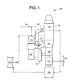
- FIG. 1 illustrates an exemplary embodiment of a hybrid power system 100.
- the system includes a HRSG 102 having an upstream intake duct portion 101 and a downstream intake duct portion 103, a heavy frame gas turbine engine 104, a light frame gas turbine engine 106, a steam turbine 108, a condenser 110, an air inlet 112, an alternator/generator 114, an alternator/generator 116, an electrical grid 105, an upstream intake duct damper 118, a downstream intake duct damper 120, and a bypass stack 122.
- the system 100 may operate in a number of different modes including, for example, cold plant start up, normal operation, and peak output operation and turndown operation.
- the system 100 begins with a cold, non-operating plant.
- the light frame gas turbine engine 106 is started, with the upstream intake duct damper 118 and the downstream intake duct damper 120 closed.
- the bypass stack 122 is open. Ambient air is received by the air inlet 112, mixed with fuel, and combusted in the light frame gas turbine engine 106.
- the alternator/generator 116 may be brought online, and the power from the alternator/generator 116 sent to the grid 105.
- the exhaust from the light frame gas turbine engine 106 is output by the bypass stack 122.
- the upstream intake duct damper 118 is opened, and the bypass stack 122 is closed-routing the exhaust from the light frame gas turbine engine 106 to the upstream intake duct portion 101 of the HRSG 102.
- the exhaust from the light frame gas turbine engine 106 begins preheating the HRSG 102 and/or a steam turbine.
- the light frame gas turbine engine 106 is designed to operate efficiently and with low pollution emissions while outputting exhaust gas at a temperature within the preheat temperature specifications of the HRSG 102 and the associated steam turbine. Once the HRSG 102 is preheated to a temperature threshold that is associated with the exhaust temperature of the light frame gas turbine engine 106, the heavy frame gas turbine engine 104 is started. The heavy frame gas turbine engine 104 operates efficiently at an exhaust temperature that is higher than the light frame gas turbine engine 106 and outputs a higher temperature exhaust into the upstream intake duct portion 101 of the HRSG 102.
- the alternator/generator 114 may be brought online and deliver power to the grid 105, the light frame gas turbine engine 106 may be shut down, and the upstream intake duct damper 118 is closed.
- the heavy frame gas turbine engine 104 exhaust continues to preheat the HRSG 102.
- the HRSG 102 may produce steam for the steam turbine 108.
- the steam turbine 108 may receive steam from another boiler (not shown) in the system 100, and the heavy frame gas turbine engine 104 may be shut down.
- the heavy frame gas turbine engine 104 may remain running and provide power to the grid 105 and exhaust gas to heat the HRSG 102.
- the light frame gas turbine engine 106 may be used with the alternator/generator 116 to provide additional power to the grid 105.
- the heavy frame gas turbine engine 104 is operating efficiently; turning the alternator/generator 114, and outputting exhaust to the upstream intake duct portion 101 of the HRSG 102.
- the light frame gas turbine engine 106 is started with the upstream intake duct damper 118 and the downstream intake duct damper 120 closed and the bypass stack 122 open. Once the light frame gas turbine engine 106 is operating at a desired output, the downstream intake duct damper 120 is opened and the bypass stack 122 is closed-routing exhaust from the light frame gas turbine engine 106 to the downstream intake duct portion 103 of the HRSG 102.
- the exhaust temperatures of the gas turbine engines are dissimilar.
- the exhaust temperature of the light frame gas turbine engine 106 operating at a desired efficiency is lower than the temperature of the heavy frame gas turbine engine 104 operating at a desired efficiency. Routing the cooler exhaust of the light frame gas turbine engine 106 to mix with the hotter exhaust of the heavy frame gas turbine engine 104 at the upstream intake duct portion 101 of the HRSG 102 is undesirable since the cooler exhaust of the light frame gas turbine engine 106 reduces the effectiveness of the hotter exhaust of the heavy frame gas turbine engine 104.
- the exhaust cools by creating steam in the HRSG 102.
- the exhaust from the heavy frame gas turbine engine 104 reaches a temperature that effectively matches the temperature of the exhaust of the light frame gas turbine engine 106.
- the region where the exhaust from the heavy frame gas turbine engine 104 reaches a temperature that effectively matches the temperature of the exhaust of the light frame gas turbine engine 106 is the input region for the downstream intake duct portion 103 of the HRSG 102.
- the exhaust of the heavy frame gas turbine engine 104 mixes with the exhaust of the light frame gas turbine engine 106 at a similar temperature in the downstream intake duct portion 103 of the HRSG 102. Routing the exhaust of the light frame gas turbine engine 106 to mix with the exhaust of the heavy frame gas turbine engine 104 in the HRSG 102 in a region where the temperatures of the exhaust are matched, allows the heavy frame gas turbine engine 104 and the light frame gas turbine engine 106 to operate at efficient output levels; providing power to the grid 105 and efficiently contributing exhaust gas to the HRSG 102.
- FIG. 2 illustrates an alternate exemplary embodiment of a hybrid power system.
- the system 200 is similar to the system 100 described above and includes a second HRSG 102 connected to a second heavy frame gas turbine engine 104 and alternator/generator 114.
- the system 200 operates similarly to the system 100 and may operate using either HRSG 102 (with a heavy frame gas turbine engine 104 and alternator/generator 114) combination alone or in tandem.
- FIG. 3 illustrates another alternate exemplary embodiment of a hybrid power system.
- the system 300 is similar to the system 100 described above, and includes a duct burner 124, but may not include a downstream intake duct portion 103 of FIG. 1 , and a downstream intake duct damper 120.
- the duct burner 124 is disposed in the exhaust path of the light frame gas turbine engine 106 of FIG.1 .
- the duct burner may raise the temperature of the exhaust flow from the gas turbine engine 106 to match the exhaust flow temperature of gas turbine engine 104.
- the resulting mixed exhaust flow temperature is maintained at the prescribed design point temperature providing for optimum HRSG steam production.
- the embodiments described above show exemplary systems. Other embodiments may include a variety of combinations of gas turbine engines, HRSGs, and steam turbines. The embodiments are not limited for example, to one or two HRSGs, but may include any number of HRSGs, gas turbine engines, and associated equipment.
- the terms light frame and heavy frame gas turbine engine are not limiting and used for illustrative purposes. For example a heavy frame gas turbine engine having desired design specifications may be substituted for a light frame gas turbine engine. Likewise, a light frame gas turbine engine may in some applications be substituted for a heavy frame gas turbine engine or any other gas turbine engine that may also be in the aero-derivative branch of gas turbine engines.
- FIG. 4 illustrates a graph of a simulated output of a hybrid plant similar to the embodiments described above.
- the graph illustrates the output in kilowatts (kW), the Heat Rate in British thermal units per kilowatt hour (Btu/KWh), and the Heat Input in (MMBtu/hr).
- the Plant Composite Heat Rate function shows the Heat Rate of an embodiment of a hybrid plant as a function of kW. Below 100,000 kW, the plant is operating with the light frame gas turbine engine 106 online, generating power from cold plant. At approximately 125,000 kW, the heavy frame gas turbine engine 104 is brought online initiating the transition between light frame gas turbine operation and heavy duty gas turbine operation. After which the light frame gas turbine engine 106 may be taken offline.
- Peak operation is shown at approximately 525,000 kW where the light frame gas turbine engine 106 is brought online increasing the peak power output of the system.
- the bottom function of the graph illustrates the Heat Input of the system as a function of kW.
- a function of a Non-composite Plant Heat Rate is illustrated that represents the Heat Rate of the system when the light frame gas turbine engine 106, is not used.
- the Non-composite Plant Heat Rate at approximately 100,000 kW is higher than the Plant Composite Heat Rate, and the Non-composite Plant does not produce power below 100,000 kW since the light frame gas turbine engine 106 is not operating.
- the high end kW output of the Non-composite Plant is also lower than the Composite Plant.
- FIG. 4 illustrate that the embodiments of the systems described above offer increased efficiency from plant startup when the light frame gas turbine engine 106 is operating and increased peak plant output and when both the light frame gas turbine engine 106 and the heavy frame gas turbine engine 104 are operating.
- the use of both a light frame and heavy frame gas turbine in a power system offer increased flexibility, system efficiency, and lower overall pollution emissions over a larger power output range.
- the cold plant startup sequence of the system 300 of FIG. 3 is similar to the cold plant startup sequence of the system 100 of FIG. 1 , with the duct burner offline.
- heavy frame gas turbine engine 104 and the light frame gas turbine engine 106 to operate at efficient output levels.
- the upstream intake duct damper 118 is opened, and the duct burner is started.
- the duct burner mixes fuel with the exhaust from the light frame gas turbine engine 106 and combusts the mixture-raising the temperature of the exhaust from the light frame gas turbine engine 106 to effectively match the temperature of the exhaust of the heavy frame gas turbine engine 104.
- the exhaust of the heavy frame gas turbine engine 104 mixes with the exhaust of the light frame gas turbine engine 106 in the upstream intake duct portion 101 of the HRSG 102 and the exhaust mixture flows through the HRSG 102 creating steam in the HRSG 102.
- the use of the duct burner 124 to heat the exhaust of the light frame gas turbine engine 106 prior to mixing the exhaust of the light frame gas turbine engine 106 with the exhaust of the heavy frame gas turbine engine 104 allows the HRSG 102 to operate efficiently while both the light frame gas turbine engine 106 and the heavy frame gas turbine engine 104 operate at peak efficient operating levels.
Abstract
Description
- The subject matter disclosed herein relates to power generation and more particularly to power generation in hybrid power plants.
- Power plants using steam turbines often include gas turbine engines. The gas turbine engines may be used during a cold start up of the plant and to increase power generation during plant operation. In a hybrid plant, the exhaust from gas turbine engines may be incorporated into the thermal cycle of the plant to increase the efficiency of steam generation. The operational specifications of gas turbines including, for example, exhaust temperatures, fuel consumption, and emissions affect the efficiency of a hybrid plant.
- According to one aspect of the invention, a system comprises a first heat recovery steam generator (HRSG) having an upstream intake duct portion, a first gas turbine engine connected to a first exhaust duct operative to output exhaust from the first gas turbine engine to the upstream intake duct portion of the first HRSG, and a second gas turbine engine connected to a second exhaust duct operative to output exhaust from the second gas turbine engine to the upstream intake duct portion of the first HRSG.
- According to another aspect of the invention, a system comprises a first heat recovery steam generator (HRSG) having an upstream intake duct portion, a first gas turbine engine connected to a first exhaust duct operative to output exhaust from the first gas turbine engine to the upstream intake duct portion of the first HRSG, a duct burner portion operative to heat the output exhaust of the first gas turbine engine, and a second gas turbine engine connected to a second exhaust duct operative to output exhaust from the second gas turbine engine to the upstream intake duct portion of the first HRSG.
- According to yet another aspect of the invention, a system comprises a first heat recovery steam generator (HRSG) having an upstream intake duct portion and a downstream intake duct portion, a first gas turbine engine operative to output exhaust to the upstream intake duct portion of the first HRSG, wherein the exhaust from the first gas turbine engine is operative to heat the first HRSG to a first temperature, a second gas turbine engine operative to output exhaust to the upstream intake duct portion of the first HRSG wherein the exhaust from the second gas turbine engine is operative to heat the first HRSG to a second temperature.
- These and other advantages and features will become more apparent from the following description taken in conjunction with the drawings.
- There follows a detailed description of embodiments of the invention by way of example only with reference to the accompanying drawings, in which:
-
FIG. 1 is an exemplary embodiment of a hybrid power system. -
FIG. 2 is an alternate exemplary embodiment of a hybrid power system. -
FIG. 3 is another alternate exemplary embodiment of a hybrid power system. -
FIG. 4 is a graph of a simulated output of a hybrid plant. - Hybrid plants include a heavy frame and aeroderivative gas turbine engine connected to a generator(s) to produce power. The aeroderivative gas turbine engine may be used, for example, during periods of peak power consumption to augment the power produced by a steam turbine. Hybrid power plants having steam turbines and gas turbine engines may incorporate heat recovery steam generators (HRSGs) that use the heat from the exhaust gas of the aeroderivative gas turbine engine to generate additional steam that powers the steam turbine. The use of the exhaust gas from the aeroderivative gas turbine engine increases the efficiency of hybrid plants at part loads and may reduce fuel consumption and pollution during loading and unloading of the power plant.
- During a cold startup of a typical plant, operation of the heavy frame gas turbine engine in a condition appropriate for preheating the cold HRSG results in undesirable levels pollutant emissions. The use of an aeroderivative gas turbine engine at operating parameters that reduce the exhaust temperature to a level appropriate for preheating the cold HRSG efficiently decreases undesirable pollutant emission levels.
- During a cold start up sequence for a hybrid plant, the exhaust from the aeroderivative gas turbine engine is used to preheat the HRSG. Preheating the HRSG starts with a cold HRSG that is gradually heated by exhaust from the aeroderivative gas turbine engine until the HRSG reaches a normal operating temperature. Operating the aeroderivative gas turbine to preheat the HRSG reduces the time the heavy frame operates at low loads and results in lower total power plant emissions of undesirable pollutants. The parameters used to define operating temperatures at startup and normal operation of the HRSG are typically defined by the designed specifications of a particular plant and the associated system components. For example, the design of the steam turbines of the plant often defines the specifications used to operate the HRSG. Systems for efficiently preheating and operating a hybrid plant are described below.
-
FIG. 1 illustrates an exemplary embodiment of ahybrid power system 100. The system includes a HRSG 102 having an upstreamintake duct portion 101 and a downstreamintake duct portion 103, a heavy framegas turbine engine 104, a light framegas turbine engine 106, asteam turbine 108, acondenser 110, anair inlet 112, an alternator/generator 114, an alternator/generator 116, anelectrical grid 105, an upstreamintake duct damper 118, a downstreamintake duct damper 120, and abypass stack 122. - The
system 100 may operate in a number of different modes including, for example, cold plant start up, normal operation, and peak output operation and turndown operation. In an exemplary cold plant startup sequence, thesystem 100 begins with a cold, non-operating plant. The light framegas turbine engine 106 is started, with the upstreamintake duct damper 118 and the downstreamintake duct damper 120 closed. Thebypass stack 122 is open. Ambient air is received by theair inlet 112, mixed with fuel, and combusted in the light framegas turbine engine 106. The alternator/generator 116 may be brought online, and the power from the alternator/generator 116 sent to thegrid 105. The exhaust from the light framegas turbine engine 106 is output by thebypass stack 122. The upstreamintake duct damper 118 is opened, and thebypass stack 122 is closed-routing the exhaust from the light framegas turbine engine 106 to the upstreamintake duct portion 101 of the HRSG 102. The exhaust from the light framegas turbine engine 106 begins preheating the HRSG 102 and/or a steam turbine. - The light frame
gas turbine engine 106 is designed to operate efficiently and with low pollution emissions while outputting exhaust gas at a temperature within the preheat temperature specifications of the HRSG 102 and the associated steam turbine. Once the HRSG 102 is preheated to a temperature threshold that is associated with the exhaust temperature of the light framegas turbine engine 106, the heavy framegas turbine engine 104 is started. The heavy framegas turbine engine 104 operates efficiently at an exhaust temperature that is higher than the light framegas turbine engine 106 and outputs a higher temperature exhaust into the upstreamintake duct portion 101 of the HRSG 102. Once the heavy framegas turbine engine 104 is operating at a desired frequency the alternator/generator 114 may be brought online and deliver power to thegrid 105, the light framegas turbine engine 106 may be shut down, and the upstreamintake duct damper 118 is closed. The heavy framegas turbine engine 104 exhaust continues to preheat the HRSG 102. Once the HRSG 102 is preheated to a desired temperature, the HRSG 102 may produce steam for thesteam turbine 108. In normal operation, thesteam turbine 108 may receive steam from another boiler (not shown) in thesystem 100, and the heavy framegas turbine engine 104 may be shut down. Alternatively, the heavy framegas turbine engine 104 may remain running and provide power to thegrid 105 and exhaust gas to heat the HRSG 102. - In peak operation, the light frame
gas turbine engine 106 may be used with the alternator/generator 116 to provide additional power to thegrid 105. In peak operation the heavy framegas turbine engine 104 is operating efficiently; turning the alternator/generator 114, and outputting exhaust to the upstreamintake duct portion 101 of the HRSG 102. The light framegas turbine engine 106 is started with the upstreamintake duct damper 118 and the downstreamintake duct damper 120 closed and thebypass stack 122 open. Once the light framegas turbine engine 106 is operating at a desired output, the downstreamintake duct damper 120 is opened and thebypass stack 122 is closed-routing exhaust from the light framegas turbine engine 106 to the downstreamintake duct portion 103 of the HRSG 102. - When the light frame
gas turbine engine 106 and the heavy framegas turbine engine 104 are each operating at an efficient output level, the exhaust temperatures of the gas turbine engines are dissimilar. Typically, the exhaust temperature of the light framegas turbine engine 106 operating at a desired efficiency is lower than the temperature of the heavy framegas turbine engine 104 operating at a desired efficiency. Routing the cooler exhaust of the light framegas turbine engine 106 to mix with the hotter exhaust of the heavy framegas turbine engine 104 at the upstreamintake duct portion 101 of the HRSG 102 is undesirable since the cooler exhaust of the light framegas turbine engine 106 reduces the effectiveness of the hotter exhaust of the heavy framegas turbine engine 104. As the exhaust from the heavy framegas turbine engine 104 flows down stream through the HRSG 102, the exhaust cools by creating steam in the HRSG 102. Eventually, the exhaust from the heavy framegas turbine engine 104 reaches a temperature that effectively matches the temperature of the exhaust of the light framegas turbine engine 106. The region where the exhaust from the heavy framegas turbine engine 104 reaches a temperature that effectively matches the temperature of the exhaust of the light framegas turbine engine 106 is the input region for the downstreamintake duct portion 103 of the HRSG 102. - Thus, the exhaust of the heavy frame
gas turbine engine 104 mixes with the exhaust of the light framegas turbine engine 106 at a similar temperature in the downstreamintake duct portion 103 of the HRSG 102. Routing the exhaust of the light framegas turbine engine 106 to mix with the exhaust of the heavy framegas turbine engine 104 in the HRSG 102 in a region where the temperatures of the exhaust are matched, allows the heavy framegas turbine engine 104 and the light framegas turbine engine 106 to operate at efficient output levels; providing power to thegrid 105 and efficiently contributing exhaust gas to the HRSG 102. -
FIG. 2 illustrates an alternate exemplary embodiment of a hybrid power system. Thesystem 200 is similar to thesystem 100 described above and includes a second HRSG 102 connected to a second heavy framegas turbine engine 104 and alternator/generator 114. In operation, thesystem 200 operates similarly to thesystem 100 and may operate using either HRSG 102 (with a heavy framegas turbine engine 104 and alternator/generator 114) combination alone or in tandem. -
FIG. 3 illustrates another alternate exemplary embodiment of a hybrid power system. Thesystem 300 is similar to thesystem 100 described above, and includes aduct burner 124, but may not include a downstreamintake duct portion 103 ofFIG. 1 , and a downstreamintake duct damper 120. Theduct burner 124 is disposed in the exhaust path of the light framegas turbine engine 106 ofFIG.1 . The duct burner may raise the temperature of the exhaust flow from thegas turbine engine 106 to match the exhaust flow temperature ofgas turbine engine 104. The resulting mixed exhaust flow temperature is maintained at the prescribed design point temperature providing for optimum HRSG steam production. - The embodiments described above show exemplary systems. Other embodiments may include a variety of combinations of gas turbine engines, HRSGs, and steam turbines. The embodiments are not limited for example, to one or two HRSGs, but may include any number of HRSGs, gas turbine engines, and associated equipment. The terms light frame and heavy frame gas turbine engine are not limiting and used for illustrative purposes. For example a heavy frame gas turbine engine having desired design specifications may be substituted for a light frame gas turbine engine. Likewise, a light frame gas turbine engine may in some applications be substituted for a heavy frame gas turbine engine or any other gas turbine engine that may also be in the aero-derivative branch of gas turbine engines.
-
FIG. 4 illustrates a graph of a simulated output of a hybrid plant similar to the embodiments described above. The graph illustrates the output in kilowatts (kW), the Heat Rate in British thermal units per kilowatt hour (Btu/KWh), and the Heat Input in (MMBtu/hr). The Plant Composite Heat Rate function shows the Heat Rate of an embodiment of a hybrid plant as a function of kW. Below 100,000 kW, the plant is operating with the light framegas turbine engine 106 online, generating power from cold plant. At approximately 125,000 kW, the heavy framegas turbine engine 104 is brought online initiating the transition between light frame gas turbine operation and heavy duty gas turbine operation. After which the light framegas turbine engine 106 may be taken offline. Peak operation is shown at approximately 525,000 kW where the light framegas turbine engine 106 is brought online increasing the peak power output of the system. The bottom function of the graph illustrates the Heat Input of the system as a function of kW. A function of a Non-composite Plant Heat Rate is illustrated that represents the Heat Rate of the system when the light framegas turbine engine 106, is not used. The Non-composite Plant Heat Rate at approximately 100,000 kW is higher than the Plant Composite Heat Rate, and the Non-composite Plant does not produce power below 100,000 kW since the light framegas turbine engine 106 is not operating. The high end kW output of the Non-composite Plant is also lower than the Composite Plant. - The functions shown in
FIG. 4 illustrate that the embodiments of the systems described above offer increased efficiency from plant startup when the light framegas turbine engine 106 is operating and increased peak plant output and when both the light framegas turbine engine 106 and the heavy framegas turbine engine 104 are operating. The use of both a light frame and heavy frame gas turbine in a power system offer increased flexibility, system efficiency, and lower overall pollution emissions over a larger power output range. - In operation, the cold plant startup sequence of the
system 300 ofFIG. 3 is similar to the cold plant startup sequence of thesystem 100 ofFIG. 1 , with the duct burner offline. In peak operation, heavy framegas turbine engine 104 and the light framegas turbine engine 106 to operate at efficient output levels. The upstreamintake duct damper 118 is opened, and the duct burner is started. The duct burner mixes fuel with the exhaust from the light framegas turbine engine 106 and combusts the mixture-raising the temperature of the exhaust from the light framegas turbine engine 106 to effectively match the temperature of the exhaust of the heavy framegas turbine engine 104. The exhaust of the heavy framegas turbine engine 104 mixes with the exhaust of the light framegas turbine engine 106 in the upstreamintake duct portion 101 of theHRSG 102 and the exhaust mixture flows through theHRSG 102 creating steam in theHRSG 102. The use of theduct burner 124 to heat the exhaust of the light framegas turbine engine 106 prior to mixing the exhaust of the light framegas turbine engine 106 with the exhaust of the heavy framegas turbine engine 104 allows theHRSG 102 to operate efficiently while both the light framegas turbine engine 106 and the heavy framegas turbine engine 104 operate at peak efficient operating levels. - While the invention has been described in detail in connection with only a limited number of embodiments, it should be readily understood that the invention is not limited to such disclosed embodiments. Rather, the invention can be modified to incorporate any number of variations, alterations, substitutions or equivalent arrangements not heretofore described, but which are commensurate with the spirit and scope of the invention. Additionally, while various embodiments of the invention have been described, it is to be understood that aspects of the invention may include only some of the described embodiments. Accordingly, the invention is not to be seen as limited by the foregoing description, but is only limited by the scope of the appended claims.
- For completeness, various aspects of the invention are now set out in the following numbered clauses:
- 1. A system comprising:
- a first heat recovery steam generator (HRSG) having an upstream intake duct portion;
- a first gas turbine engine connected to a first exhaust duct operative to output exhaust from the first gas turbine engine to the upstream intake duct portion of the first HRSG; and
- a second gas turbine engine connected to a second exhaust duct operative to output exhaust from the second gas turbine engine to the upstream intake duct portion of the first HRSG.
- 2. The system of clause 1, wherein the system further comprises an exhaust duct connected to the first gas turbine engine operative to output exhaust from the first gas turbine engine to a downstream intake duct portion of the first HRSG.
- 3. The system of clause 1, wherein the system further comprises a second HRSG having an upstream intake duct portion.
- 4. The system of clause 3, wherein the system further comprises an exhaust duct connected to the first gas turbine engine operative to output exhaust from the first gas turbine engine to the upstream intake duct portion of the second HRSG.
- 5. The system of clause 3, wherein the system further comprises an exhaust duct connected to the second gas turbine engine operative to output exhaust from the second gas turbine engine to the upstream intake duct portion of the second HRSG.
- 6. The system of clause 3, wherein the system further comprises an exhaust duct connected to the first gas turbine engine operative to output exhaust from the first gas turbine engine to a downstream intake duct portion of the second HRSG.
- 7. The system of clause 1, wherein the output exhaust from the first gas turbine engine to the upstream intake duct portion of the first HRSG is operative to heat the first HRSG.
- 8. The system of clause 1, wherein the output exhaust from the second gas turbine engine to the upstream intake duct portion of the first HRSG is operative to heat the first HRSG.
- 9. The system of clause 1, wherein a temperature of the output exhaust from the first gas turbine engine to the downstream intake duct portion of the first HRSG is lower than a temperature of the output exhaust from the second gas turbine engine to the upstream intake duct portion of the first HRSG.
- 10. A system comprising:
- a first heat recovery steam generator (HRSG) having an upstream intake duct portion;
- a first gas turbine engine connected to a first exhaust duct operative to output exhaust from the first gas turbine engine to the upstream intake duct portion of the first HRSG;
- a duct burner portion operative to heat the output exhaust of the first gas turbine engine; and
- a second gas turbine engine connected to a second exhaust duct operative to output exhaust from the second gas turbine engine to the upstream intake duct portion of the first HRSG.
- 11. The system of clause 10, wherein the system further comprises a second HRSG having an upstream intake duct portion.
- 12. The system of clause 11, wherein the system further comprises an exhaust duct connected to the first gas turbine engine operative to output exhaust from the first gas turbine engine to the upstream intake duct portion of the second HRSG.
- 13. The system of clause 10, wherein the system further comprises an exhaust duct connected to the second gas turbine engine operative to output exhaust from the second gas turbine engine to the upstream intake duct portion of the second HRSG.
- 14. The system of clause 10, wherein the output exhaust from the first gas turbine engine to the upstream intake duct portion of the first HRSG is operative to heat the first HRSG.
- 15. The system of clause 10, wherein the output exhaust from the second gas turbine engine to the upstream intake duct portion of the first HRSG is operative to heat the first HRSG.
- 16. The system of clause 10, wherein the a duct burner portion is further operative to heat the output exhaust of the first gas turbine engine to a temperature that approximately matches the temperature of the output exhaust from the second gas turbine engine.
- 17. A system comprising:
- a first heat recovery steam generator (HRSG) having an upstream intake duct portion and a downstream intake duct portion;
- a first gas turbine engine operative to output exhaust to the upstream intake duct portion of the first HRSG, wherein the exhaust from the first gas turbine engine is operative to heat the first HRSG to a first temperature;
- a second gas turbine engine operative to output exhaust to the upstream intake duct portion of the first HRSG wherein the exhaust from the second gas turbine engine is operative to heat the first HRSG to a second temperature.
- 18. The system of clause 17, wherein the second temperature is greater than the first temperature.
- 19. The system of clause 17, wherein the first gas turbine engine is further operative to output exhaust to the downstream intake duct portion of the first HRSG.
- 20. The system of clause 17, wherein the system further comprises a duct burner portion operative to heat the output exhaust of the first gas turbine engine.
Claims (9)
- A system comprising:a first heat recovery steam generator (HRSG) (102) having an upstream intake duct portion (101);a first gas turbine engine (106) connected to a first exhaust duct operative to output exhaust from the first gas turbine engine (106) to the upstream intake duct portion (101) of the first HRSG (102); anda second gas turbine engine (104) connected to a second exhaust duct operative to output exhaust from the second gas turbine engine (104) to the upstream intake duct portion (101) of the first HRSG (106).
- The system of claim 1, wherein the system further comprises an exhaust duct connected to the first gas turbine engine (106) operative to output exhaust from the first gas turbine engine (106) to a downstream intake duct portion (103) of the first HRSG (106).
- The system of claim 1 or 2, wherein the system further comprises a second HRSG (106) having an upstream intake duct portion (101).
- The system of claim 3, wherein the system further comprises an exhaust duct connected to the first gas turbine engine (106) operative to output exhaust from the first gas turbine engine (106) to the upstream intake duct portion (101) of the second HRSG (102).
- The system of claim 3, wherein the system further comprises an exhaust duct connected to the second gas turbine engine (104) operative to output exhaust from the second gas turbine engine (104) to the upstream intake duct portion (101) of the second HRSG (102).
- The system of claim 3, wherein the system further comprises an exhaust duct connected to the first gas turbine engine (106) operative to output exhaust from the first gas turbine engine (106) to a downstream intake duct portion (103) of the second HRSG (102).
- The system of any of the preceding claims, wherein the output exhaust from the first gas turbine engine (106) to the upstream intake duct portion (101) of the first HRSG (102) is operative to heat the first HRSG (102).
- The system of any of the preceding claims, wherein the output exhaust from the second gas turbine engine (104) to the upstream intake duct portion (101) of the first HRSG (102) is operative to heat the first HRSG (102).
- The system of any of the preceding claims, wherein a temperature of the output exhaust from the first gas turbine engine (106) to the downstream intake duct portion (103) of the first HRSG (102) is lower than a temperature of the output exhaust from the second gas turbine engine (104) to the upstream intake duct portion (101) of the first HRSG (102).
Applications Claiming Priority (1)
| Application Number | Priority Date | Filing Date | Title |
|---|---|---|---|
| US12/423,415 US20100257837A1 (en) | 2009-04-14 | 2009-04-14 | Systems involving hybrid power plants |
Publications (2)
| Publication Number | Publication Date |
|---|---|
| EP2423461A2 true EP2423461A2 (en) | 2012-02-29 |
| EP2423461A3 EP2423461A3 (en) | 2013-12-25 |
Family
ID=42933230
Family Applications (1)
| Application Number | Title | Priority Date | Filing Date |
|---|---|---|---|
| EP10159604.7A Withdrawn EP2423461A3 (en) | 2009-04-14 | 2010-04-12 | Systems Involving Hybrid Power Plants |
Country Status (4)
| Country | Link |
|---|---|
| US (1) | US20100257837A1 (en) |
| EP (1) | EP2423461A3 (en) |
| JP (1) | JP2010249132A (en) |
| CN (1) | CN101865031A (en) |
Families Citing this family (6)
| Publication number | Priority date | Publication date | Assignee | Title |
|---|---|---|---|---|
| FI121581B (en) * | 2009-05-08 | 2011-01-14 | Foster Wheeler Energia Oy | Thermal power boiler |
| US10094275B2 (en) * | 2016-01-26 | 2018-10-09 | General Electric Company | Operation scheduling for optimal performance of hybrid power plants |
| JP6045737B1 (en) * | 2016-03-03 | 2016-12-14 | 三菱日立パワーシステムズ株式会社 | Remodeling method of combined cycle plant, distribution duct, combined cycle plant |
| WO2019094453A1 (en) | 2017-11-09 | 2019-05-16 | Mitsubishi Hitachi Power Systems Americas, Inc. | Additional powering for combined cycle power plants |
| FR3082225B1 (en) * | 2018-06-07 | 2020-06-05 | Safran Helicopter Engines | ASYMMETRIC PROPULSIVE HEAT RECOVERY SYSTEM |
| ES2964474T3 (en) * | 2021-03-17 | 2024-04-08 | Itp Engines Uk Ltd | Aircraft powerplant comprising a recuperative closed cycle arrangement |
Family Cites Families (26)
| Publication number | Priority date | Publication date | Assignee | Title |
|---|---|---|---|---|
| US1925646A (en) * | 1933-06-29 | 1933-09-05 | Foster Wheeler Corp | Waste heat boiler heated by gases from diesel engines or the like |
| US3796045A (en) * | 1971-07-15 | 1974-03-12 | Turbo Dev Inc | Method and apparatus for increasing power output and/or thermal efficiency of a gas turbine power plant |
| US4044549A (en) * | 1972-12-11 | 1977-08-30 | Zwick Eugene B | Low emission combustion process and apparatus |
| CH601651A5 (en) * | 1975-05-14 | 1978-07-14 | Bbc Brown Boveri & Cie | |
| US4136643A (en) * | 1977-08-15 | 1979-01-30 | Sulzer Brothers Limited | Waste heat steam generator |
| CH623888A5 (en) * | 1977-10-04 | 1981-06-30 | Bbc Brown Boveri & Cie | |
| SE463776B (en) * | 1989-05-26 | 1991-01-21 | Nonox Eng Ab | PROCEDURE FOR PRODUCING ELECTRIC ENERGY WITH AN ACFBC ON-GENERATOR COMBINED WITH A RURAL UNIT AND TWO GAS TURBIN UNITS |
| US5212942A (en) * | 1990-11-09 | 1993-05-25 | Tiernay Turbines, Inc. | Cogeneration system with recuperated gas turbine engine |
| US5247907A (en) * | 1992-05-05 | 1993-09-28 | The M. W. Kellogg Company | Process furnace with a split flue convection section |
| US5628183A (en) * | 1994-10-12 | 1997-05-13 | Rice; Ivan G. | Split stream boiler for combined cycle power plants |
| US5771678A (en) * | 1996-02-12 | 1998-06-30 | Shouman; Ahmad R. | Water-injected stoichiometric-combustion gas turbine engine |
| WO1999020947A1 (en) * | 1997-10-16 | 1999-04-29 | Toyota Jidosha Kabushiki Kaisha | Catalytic combustion heater |
| US6230480B1 (en) * | 1998-08-31 | 2001-05-15 | Rollins, Iii William Scott | High power density combined cycle power plant |
| US6237337B1 (en) * | 1998-09-10 | 2001-05-29 | Ormat Industries Ltd. | Retrofit equipment for reducing the consumption of fossil fuel by a power plant using solar insolation |
| US6321539B1 (en) * | 1998-09-10 | 2001-11-27 | Ormat Industries Ltd. | Retrofit equipment for reducing the consumption of fossil fuel by a power plant using solar insolation |
| DE19926326A1 (en) * | 1999-06-09 | 2000-12-14 | Abb Alstom Power Ch Ag | Process and plant for heating a liquid medium |
| DE10022243A1 (en) * | 2000-05-08 | 2002-02-21 | Alstom Power Nv | Process for operating a combined cycle power plant and combined cycle power plant for carrying out the process |
| US6430915B1 (en) * | 2000-08-31 | 2002-08-13 | Siemens Westinghouse Power Corporation | Flow balanced gas turbine power plant |
| US6782703B2 (en) * | 2002-09-11 | 2004-08-31 | Siemens Westinghouse Power Corporation | Apparatus for starting a combined cycle power plant |
| US7121078B2 (en) * | 2003-01-28 | 2006-10-17 | General Electric Company | Methods and apparatus for operating gas turbine engines |
| US6968674B2 (en) * | 2003-01-28 | 2005-11-29 | General Electric Company | Methods and apparatus for operating gas turbine engines |
| US7107774B2 (en) * | 2003-08-12 | 2006-09-19 | Washington Group International, Inc. | Method and apparatus for combined cycle power plant operation |
| JP2005069087A (en) * | 2003-08-22 | 2005-03-17 | Takuma Co Ltd | Cogeneration system |
| US20050166981A1 (en) * | 2004-02-04 | 2005-08-04 | Bachmann Industries, Inc. | Actuation system for fluid flow diverter |
| US20060272334A1 (en) * | 2005-06-01 | 2006-12-07 | Pavol Pranda | Practical method for improving the efficiency of cogeneration system |
| US7726114B2 (en) * | 2005-12-07 | 2010-06-01 | General Electric Company | Integrated combustor-heat exchanger and systems for power generation using the same |
-
2009
- 2009-04-14 US US12/423,415 patent/US20100257837A1/en not_active Abandoned
-
2010
- 2010-04-07 JP JP2010088258A patent/JP2010249132A/en not_active Withdrawn
- 2010-04-12 EP EP10159604.7A patent/EP2423461A3/en not_active Withdrawn
- 2010-04-12 CN CN201010167020A patent/CN101865031A/en active Pending
Non-Patent Citations (1)
| Title |
|---|
| None |
Also Published As
| Publication number | Publication date |
|---|---|
| US20100257837A1 (en) | 2010-10-14 |
| EP2423461A3 (en) | 2013-12-25 |
| JP2010249132A (en) | 2010-11-04 |
| CN101865031A (en) | 2010-10-20 |
Similar Documents
| Publication | Publication Date | Title |
|---|---|---|
| US8051654B2 (en) | Reheat gas and exhaust gas regenerator system for a combined cycle power plant | |
| KR101588209B1 (en) | Stand-by operation of a gas turbine | |
| US6442941B1 (en) | Compressor discharge bleed air circuit in gas turbine plants and related method | |
| US20070130952A1 (en) | Exhaust heat augmentation in a combined cycle power plant | |
| EP2423461A2 (en) | Systems Involving Hybrid Power Plants | |
| KR20090045392A (en) | Gas turbine | |
| JP2013221506A (en) | Method and system for controlling powerplant during low-load operation | |
| CN106762158B (en) | System and method for operating a gas turbine while maintaining emissions standards | |
| WO2018143310A1 (en) | Hydrogen/oxygen equivalent combustion turbine system | |
| EP3314166B1 (en) | Method and equipment for combustion of ammonia | |
| US20060087294A1 (en) | Gas turbine apparatus | |
| JP2001525033A (en) | Reheat partial oxidation power plant and method | |
| EP2522829A2 (en) | A steam injected gas turbine engine | |
| US9169777B2 (en) | Gas turbine engine with water and steam injection | |
| US5906094A (en) | Partial oxidation power plants and methods thereof | |
| EP2578840A2 (en) | Power plant with exhaust gas recirculation system | |
| US8640437B1 (en) | Mini sized combined cycle power plant | |
| JP6382755B2 (en) | Fuel cell combined power generation system and operation method thereof | |
| JPH10213317A (en) | Refuse incinerator operation method | |
| JP2004060478A (en) | Binary fluid gas turbine, its operation method, and repowering method for gas turbine | |
| Cenusa et al. | On gas turbines and combined cycles | |
| Cenusa et al. | OVERVIEW ON GAS TURBINES AND COMBINED CYCLES WITH NO^ sub X^ REDUCTION CONSIDERATION | |
| Fielder | The Advanced Cycle Low-Power (ACL) Gas Turbine Alternator Project | |
| JPH11210490A (en) | Gas turbine power generation system | |
| JPS62135619A (en) | Heat supply power generating device using gas turbine |
Legal Events
| Date | Code | Title | Description |
|---|---|---|---|
| AK | Designated contracting states |
Kind code of ref document: A2 Designated state(s): AT BE BG CH CY CZ DE DK EE ES FI FR GB GR HR HU IE IS IT LI LT LU LV MC MK MT NL NO PL PT RO SE SI SK SM TR |
|
| AX | Request for extension of the european patent |
Extension state: AL BA ME RS |
|
| PUAI | Public reference made under article 153(3) epc to a published international application that has entered the european phase |
Free format text: ORIGINAL CODE: 0009012 |
|
| PUAL | Search report despatched |
Free format text: ORIGINAL CODE: 0009013 |
|
| AK | Designated contracting states |
Kind code of ref document: A3 Designated state(s): AT BE BG CH CY CZ DE DK EE ES FI FR GB GR HR HU IE IS IT LI LT LU LV MC MK MT NL NO PL PT RO SE SI SK SM TR |
|
| AX | Request for extension of the european patent |
Extension state: AL BA ME RS |
|
| RIC1 | Information provided on ipc code assigned before grant |
Ipc: F01K 13/02 20060101AFI20131119BHEP Ipc: F02C 6/00 20060101ALI20131119BHEP Ipc: F02C 7/10 20060101ALI20131119BHEP Ipc: F01K 23/10 20060101ALI20131119BHEP |
|
| STAA | Information on the status of an ep patent application or granted ep patent |
Free format text: STATUS: THE APPLICATION IS DEEMED TO BE WITHDRAWN |
|
| 18D | Application deemed to be withdrawn |
Effective date: 20140626 |