EP2423383A1 - Walze für eine Papier- oder Kartonmaschine - Google Patents
Walze für eine Papier- oder Kartonmaschine Download PDFInfo
- Publication number
- EP2423383A1 EP2423383A1 EP11173542A EP11173542A EP2423383A1 EP 2423383 A1 EP2423383 A1 EP 2423383A1 EP 11173542 A EP11173542 A EP 11173542A EP 11173542 A EP11173542 A EP 11173542A EP 2423383 A1 EP2423383 A1 EP 2423383A1
- Authority
- EP
- European Patent Office
- Prior art keywords
- pressure chamber
- pressure
- roller
- throttle
- chamber
- Prior art date
- Legal status (The legal status is an assumption and is not a legal conclusion. Google has not performed a legal analysis and makes no representation as to the accuracy of the status listed.)
- Granted
Links
- 230000002093 peripheral effect Effects 0.000 claims description 2
- 238000013016 damping Methods 0.000 description 24
- 239000007789 gas Substances 0.000 description 6
- 230000010355 oscillation Effects 0.000 description 6
- IJGRMHOSHXDMSA-UHFFFAOYSA-N Atomic nitrogen Chemical compound N#N IJGRMHOSHXDMSA-UHFFFAOYSA-N 0.000 description 4
- 239000012530 fluid Substances 0.000 description 4
- 230000010349 pulsation Effects 0.000 description 4
- 230000005489 elastic deformation Effects 0.000 description 3
- 230000006978 adaptation Effects 0.000 description 2
- 238000005452 bending Methods 0.000 description 2
- 239000000463 material Substances 0.000 description 2
- 239000012528 membrane Substances 0.000 description 2
- 239000002184 metal Substances 0.000 description 2
- 229910052757 nitrogen Inorganic materials 0.000 description 2
- 230000003321 amplification Effects 0.000 description 1
- 239000002131 composite material Substances 0.000 description 1
- 230000003292 diminished effect Effects 0.000 description 1
- 238000005553 drilling Methods 0.000 description 1
- 230000002349 favourable effect Effects 0.000 description 1
- 239000002657 fibrous material Substances 0.000 description 1
- 238000002955 isolation Methods 0.000 description 1
- 238000004519 manufacturing process Methods 0.000 description 1
- 230000013011 mating Effects 0.000 description 1
- 230000007246 mechanism Effects 0.000 description 1
- 238000003199 nucleic acid amplification method Methods 0.000 description 1
- 230000003534 oscillatory effect Effects 0.000 description 1
- 230000000737 periodic effect Effects 0.000 description 1
Images


Classifications
-
- F—MECHANICAL ENGINEERING; LIGHTING; HEATING; WEAPONS; BLASTING
- F16—ENGINEERING ELEMENTS AND UNITS; GENERAL MEASURES FOR PRODUCING AND MAINTAINING EFFECTIVE FUNCTIONING OF MACHINES OR INSTALLATIONS; THERMAL INSULATION IN GENERAL
- F16C—SHAFTS; FLEXIBLE SHAFTS; ELEMENTS OR CRANKSHAFT MECHANISMS; ROTARY BODIES OTHER THAN GEARING ELEMENTS; BEARINGS
- F16C13/00—Rolls, drums, discs, or the like; Bearings or mountings therefor
- F16C13/02—Bearings
- F16C13/022—Bearings supporting a hollow roll mantle rotating with respect to a yoke or axle
- F16C13/024—Bearings supporting a hollow roll mantle rotating with respect to a yoke or axle adjustable for positioning, e.g. radial movable bearings for controlling the deflection along the length of the roll mantle
- F16C13/026—Bearings supporting a hollow roll mantle rotating with respect to a yoke or axle adjustable for positioning, e.g. radial movable bearings for controlling the deflection along the length of the roll mantle by fluid pressure
- F16C13/028—Bearings supporting a hollow roll mantle rotating with respect to a yoke or axle adjustable for positioning, e.g. radial movable bearings for controlling the deflection along the length of the roll mantle by fluid pressure with a plurality of supports along the length of the roll mantle, e.g. hydraulic jacks
-
- D—TEXTILES; PAPER
- D21—PAPER-MAKING; PRODUCTION OF CELLULOSE
- D21G—CALENDERS; ACCESSORIES FOR PAPER-MAKING MACHINES
- D21G1/00—Calenders; Smoothing apparatus
- D21G1/0073—Accessories for calenders
- D21G1/008—Vibration-preventing or -eliminating devices
-
- D—TEXTILES; PAPER
- D21—PAPER-MAKING; PRODUCTION OF CELLULOSE
- D21G—CALENDERS; ACCESSORIES FOR PAPER-MAKING MACHINES
- D21G1/00—Calenders; Smoothing apparatus
- D21G1/02—Rolls; Their bearings
- D21G1/0206—Controlled deflection rolls
- D21G1/0213—Controlled deflection rolls with deflection compensation means acting between the roller shell and its supporting member
- D21G1/022—Controlled deflection rolls with deflection compensation means acting between the roller shell and its supporting member the means using fluid pressure
Definitions
- the invention relates to a roller, in particular for a paper or board machine, with a circumferential roll shell and a fixed yoke, which passes through the roll shell axially, wherein the roll shell by the pressure in at least one pressure chamber is radially outwardly resilient and the pressure chamber via a throttle point is connected to a pressure medium line, and wherein the pressure chamber is connected via at least one channel with at least one pressure chamber having a variable volume.
- Such rolls are used as bending compensating rolls, as floating rolls or as shoe rolls for forming a nip with a counter roll.
- a fibrous material web usually a paper or board web guided and applied in the nip with increased pressure and optionally elevated temperature.
- the roll and in particular the roll mantle is subjected during operation, for example, by inhomogeneities, anisotropies or geometrical errors, but also by variations in paper thickness with exciter forces, which cause the roll mantle to vibrate.
- the resulting oscillating motion is usually so small that it does not disturb immediately.
- these oscillatory movements are reflected in the roll shell after a relatively long period of time, which leads to a further amplification of vibration. This manifests itself on the one hand as acoustic oscillations, ie in an increased sound level, but can also lead to periodic variations in thickness of the material web, the so-called barring -Erscheinung.
- three particularly pronounced natural frequencies can be measured in a calender with a mating roll and a roll.
- a particularly low natural frequency in the order of 10 to 40 Hz is excited by the rotational frequency of the roller or the counter-roller, so that the roller and the counter-roller oscillate in phase.
- a natural frequency is measured whose size is 100 - 300 Hz. This is an antiphase oscillation between roller and counter-roller, which originates mainly from the Jocheigenfrequenz.
- the third striking natural frequency is 500 to 800 Hz and also describes an antiphase oscillation of roller and counter roll, here dominated by the contact own frequency of the shell of the roller.
- the vibration of the roll mantle is transmitted either directly or by a support element to a pressure medium arranged in the pressure chamber, which is thereby pushed back and forth over the throttle point.
- the system absorbs vibration energy in the throttle point by friction, so that an attenuation of the vibration takes place, the throttle point must be designed so that enough oil can pulsate through the throttle point.
- a bending compensating roll has been proposed in which the pressure chamber via throttle points is first connected to a pressure chamber, wherein the pressure chamber is connected via a throttle point to a pressure medium line between the pressure medium line and the pressure chamber is thus arranged in series a pressure chamber which causes isolation of the pressure medium line.
- the pressure chamber may have a partially elastic boundary wall, by the elastic deformation of a further vibration damping is achieved.
- the invention is therefore based on the object, even at high frequencies to achieve a good vibration damping,
- this object is achieved in a roller of the type mentioned above in that the pressure chamber has a maximum volume of 0.025 to 0.16 liters and the channel has a second throttle.
- the moving through the vibrations of the roll shell hydraulic fluid can be pushed back and forth not only on the throttle point, but also on the at least one channel with the second throttle in at least one pressure chamber whose volume is changed by the corresponding pressure fluctuations.
- a volume range of 0.025 to 0.16 liters has proven to be advantageous depending on the size of the support element.
- the channels with the second throttle as well as the throttle point go directly from the pressure chamber. In this case, a multiple vibration damping is achieved in parallel.
- a first vibration damping by the reciprocating motion of the hydraulic fluid via the throttle point a second damping by the reciprocating motion of the hydraulic fluid through the channels and the second throttle and a third damping by changing the volume of the pressure chamber, ie an elastic Deformation.
- a very effective vibration damping is achieved, which is ensured by the various damping mechanisms, even at high frequencies good vibration damping.
- the flow cross section of the second throttle is 1 to 2 times as large as the flow cross section of the throttle point. If a suitable flow resistance value has been found for the throttle point to the pressure medium line, then the intensity of the natural frequency, which results from the Jocheigenfrequenz , very well diminished. In order to match the higher natural frequency of the contact own frequency of the shell with the counter roll accordingly To dampen the second throttle is to choose with a correspondingly larger flow cross-section.
- the pressure chamber is arranged in the yoke, wherein in the pressure chamber, a support element is guided, which can be pressed by a pressure in the pressure chamber with an application side against the roll shell.
- the support element is generally feasible radially in the pressure chamber and limits one side of the pressure chamber. It can be arranged between the support member and a peripheral surface of the pressure chamber, a seal. The support element forms one side of the pressure chamber.
- oil chambers may be formed which serve to form an oil film between the abutment side of the support member and an inner side of the roll shell.
- This oil film may be, for example 20 to 50 microns thick and is very stiff, so that there is almost no vibration damping
- the vibrations of the roll shell are thus transferred directly to the support member which swings accordingly with the roll shell within the pressure chamber and so the vibration on the in
- the support member may be formed as a shoe shoe shoe, but it may also be arranged a plurality of support elements in a corresponding number of pressure chambers axially adjacent to each other, so that a deflection compensating roller is obtained by the arrangement of the pressure chamber in the yoke, this can be relatively good to the outside be sealed. There is enough space available within the yoke anyway.
- the pressure medium line can be performed, for example, axially through the yoke.
- the pressure chamber is disposed within the pressure chamber. This has the advantage of using a hole available for the support element for a further purpose can. It must therefore be provided no further recess or hole on the yoke. In addition, the use of such a pressure chamber can be quickly and easily retrofitted even with existing rollers.
- the pressure chamber is accommodated in a recess or a bore in the yoke between the support elements. This is especially true for Biegeeinstellwalzen with support elements, in which the bore for the support element no longer offers enough space for the pressure chamber.
- the pressure space which may be, for example, a hydraulic accumulator, in particular a diaphragm accumulator, also known as ball accumulator, without coming too close to the roll shell, but still close enough to be at the pressure chamber. It is preferable not to make the hole for the pressure chamber in the same direction of the hole as the cylinder space for the support member so as not to weaken the yoke too much.
- the pressure chamber is fluid-tightly separated by a movable and / or elastic wall from a chamber which is filled with a compressible medium.
- a compressible medium for example, a gas such as air or nitrogen can be used. But it is also possible to use an elastic plastic material.
- the compressible Medium can be influenced by the forces required for the deformation and / or movement of the wall, whereby an adjustment can be made to certain frequencies in which a particularly good attenuation is achieved.
- the chamber and / or the wall can also be used as at least one additional element.
- the wall may be formed as an elastomeric membrane, but also as a thin metal band or as a composite band, and even as a piston.
- a plurality of pressure chambers in the axial direction of the roller are arranged side by side.
- the storage tanks can then be connected to different pressure chambers. If the pressure chambers are at least partially dimensioned differently, and / or the properties of the wall or the compressible medium are different, a vote can be made to different frequencies. Overall, a very wide frequency band can be damped very effectively.
- the chamber has a pressure port or is hermetically sealed.
- a gas such as air or nitrogen can be used as a compressible medium. If the chamber has a pressure connection, a subsequent adjustment of the damping properties is possible, a hermetically sealed design, however, has the advantage that a virtually maintenance-free operation is possible.
- a number and / or a cross-sectional area and / or a length of the throttle point and / or the second throttle are variable with at least one control element, which is designed in particular as a hydraulic, electrical, magnetic or piezoelectric actuator.
- At least one vibration sensor is arranged on the roll shell and / or on the yoke and / or on the support element and / or in the pressure chamber.
- this vibration sensor the vibration of the roll shell can be determined directly and used, for example, to control the control element, thereby maximizing the damping is possible
- an actuator in particular a piezoelectric element is provided on the wall.
- the wall can be purposefully set in oscillations which are set against the vibrations generated by the roll shell.
- an active vibration damping is possible.
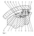
- Fig. 1 shows in cross section a roller with a fixed yoke 1 and a rotating roll shell 2.
- the yoke 1 passes through the roll shell 2 axially.
- the roll shell 2 is pressed by means of a support member 3 radially outward.
- the supporting element 3 rests with an abutment side 4 on an inner side 5 of the roll mantle 2.
- the support member 3 has on its landing page 4 pressure pockets 6, in which oil is added to form an oil film between the Anlegeseite 4 and the inner side 5.
- the support element 3 is guided with a cylindrical extension 7 in a pressure chamber 8 radially movable. Via a throttle point 10, the pressure chamber 8 is connected to a pressure medium line 12 which is guided through the yoke 1 to the outside and serves to supply the pressure chamber 8 with a pressurized pressure medium.
- the position of the support element 3 with respect to the yoke 1 is determined.
- the support member 3 is pressed radially outward and thus presses against the roll shell 2.
- the support element 3 With a reduction in the pressure in the pressure chamber 8, the support element 3 by the elasticity of the roll shell 2 and by a counter-roll, the presses on the roll shell 2, moved radially inward.
- a seal in particular a screwed ring seal 15, may be provided between the extension 7 of the support element 3 and a boundary of the pressure chamber 8.
- the pressure chamber 14 is formed in this example outside the cylinder bore 9 for the support member 3. However, it could also be located within the pressure chamber 8. It has a maximum volume of 0.025 to 0.16 liters.
- the pressure chamber 14 is separated from a chamber 17 by an elastic wall.
- a second throttle 11 is provided in the channel 13. In the channel 13, a second throttle 11 is provided. In this throttle, the flow resistance is lower than at the throttle point 10.
- the pressure chamber 14 via a second throttle 11 with a larger cross section than the cross section of the throttle point 10 with the pressure chamber 8.
- a preferred ratio of the cross sections of throttle 11 to throttle point 10 is in of the order of 1 to 2.
- the chamber 17 is filled with a compressible medium.
- the chamber 17 can be filled via a supply line 19 with a gaseous medium.
- the pressure in the chamber 17 can be adjusted individually, whereby an adaptation to different vibration frequencies is possible.
- the pressure chamber 14 has a variable volume due to the elastic deformation of the wall.
- the pressure chamber 14 with the corresponding chamber 17 and the wall 16 can individually be tuned to a specific pressure or a frequency.
- a port 23 is provided to fill gas.
- the bore 18 for receiving the pressure chamber 14 is in FIG. 1
- An angle between these axes of 30 to 60 ° has been found to be most suitable.
- This arrangement is particularly good in the three-dimensional roller cutout of FIG. 2 to recognize.
- a pressure chamber 14 is connected to a V-shaped channel 13 is equal to two cylinder bores 9 and thus with two pressure chambers 8. This increases the setting possibilities and the redundancy.
- FIG. 3 is shown in an enlarged sectional view of a pressure chamber 14 with a channel 13 and a chamber 17, wherein between the pressure chamber 14 and the chamber 17, an elastic wall 16 is arranged.
- the channel 13 opens into a boundary wall of the pressure chamber 8.
- the pressure chamber 14 is connected via the second throttle 11 and the channel 13 directly to the pressure chamber 8 in connection.
- the pressure chamber 14 is formed in the yoke 1, over which an additional element 20 is inserted.
- the additional element 20 has a cavity which forms the chamber 17.
- the chamber 17 has on the pressure chamber 14 facing side of the additional element 20, the wall 16, which is formed in this embodiment by a metal strip. The wall 16 thus separates the chamber 17 from the pressure chamber 14.
- at least one seal 22 is arranged.
- the additional element 20 has a port 23, through which a compressible medium can be introduced into the chamber 17. As a result, the vibrational capability of the wall 16 is influenced.
- the additional element is attached to the yoke 1 by means of fastening means 21 shown only symbolically.
- the actuator 24 On the wall 16 designed as a piezoceramic actuator 24 is mounted, which serves to put the wall 16 in vibration, whose direction is indicated by arrows. In addition to the active introduction of a vibration, however, the actuator 24 can also be used to influence the rigidity of the wall 16.
- the actuator 24 By the actuator 24 so the volume, the chamber 17 and the pressure chamber 14 can be actively changed.
- the pulsation damper which is formed by the pressure chambers, the channels, the second throttle, the walls and the chambers, can be specifically influenced and tuned to the desired frequency.
- Measuring sensors can be used to measure the oscillation of the roll mantle or of the support element or also the pressure changes in the pressure chamber 8, these being used for tuning the pulsation damper.
- the size of the throttle point 10 or the second throttle 11, so the free cross-section is influenced by means of adjusting elements. With additional control elements can be ensured that individual channels are closed, so that the damping properties can be influenced. The movement of the control elements can in Dependence of each directly measured vibrations take place, Also a control of the control elements from the outside may be possible.
- Each pressure chamber forms with a chamber, a channel, a second throttle and a wall between the chamber and the pressure chamber each have a pulsation damper, which can be tuned to a specific frequency.
- a pulsation damper which can be tuned to a specific frequency.
Landscapes
- Physics & Mathematics (AREA)
- Fluid Mechanics (AREA)
- Engineering & Computer Science (AREA)
- General Engineering & Computer Science (AREA)
- Mechanical Engineering (AREA)
- Rolls And Other Rotary Bodies (AREA)
- Paper (AREA)
Abstract
Description
- Die Erfindung betrifft eine Walze, insbesondere für eine Papier- oder Kartonmaschine, mit einem umlaufenden Walzenmantel und einem feststehenden Joch, das den Walzenmantel axial durchsetzt, wobei der Walzenmantel durch den Druck in mindestens einer Druckkammer radial nach außen belastbar ist und die Druckkammer über eine Drosselstelle mit einer Druckmittelleitung verbunden ist, und wobei die Druckkammer über mindestens einen Kanal mit mindestens einem Druckraum verbunden ist, der ein veränderbares Volumen aufweist.
- Derartige Walzen werden als Biegeausgleichswalzen, als schwimmende Walzen oder als Schuhwalzen zur Bildung eines Nips mit einer Gegenwalze eingesetzt. Durch den Nip wird eine faserförmige Materialbahn, in der Regel eine Papier- oder Kartonbahn geführt und im Nip mit erhöhtem Druck und gegebenenfalls erhöhter Temperatur beaufschlagt.
- Die Walze und insbesondere der Walzenmantel wird im Betrieb beispielsweise durch Inhomogenitäten, Anisotropien oder Geometriefehlern, aber auch durch Papierdickenschwankungen mit Erregerkräften beaufschlagt, die ein Schwingen des Walzenmantels bewirken. Die resultierende Schwingbewegung ist in der Regel so klein, dass sie nicht unmittelbar stört. Allerdings prägen sich diese Schwingungsbewegungen nach einem längeren Zeitraum in den Walzenmantel ein, was zu einer weiteren Schwingungsverstärkung führt Dies macht sich zum einen als akustische Schwingungen bemerkbar, also in einem erhöhten Schallpegel, kann aber auch zu periodischen Dickenschwankungen der Materialbahn führen, der so genannten Barring-Erscheinung.
- In der Regel sind in einem Kalander mit einer Gegenwalze und einer besagten Walze drei besonders ausgeprägte Eigenfrequenzen messbar. Eine besonders niedrige Eigenfrequenz in der Größenordnung von 10 bis 40 Hz wird durch die Drehfrequenz der Walze oder der Gegenwalze angeregt, so dass die Walze und die Gegenwalze gleichphasig schwingen. Des Weiteren ist eine Eigenfrequenz zu messen, deren Größe bei 100 - 300 Hz liegt. Hier handelt es sich um eine gegenphasige Schwingung zwischen Walze und Gegenwalze, die vorwiegend aus der Jocheigenfrequenz herrührt. Die dritte markante Eigenfrequenz liegt bei 500 bis 800 Hz und beschreibt ebenfalls ein gegenphasiges Schwingen von Walze und Gegenwalze, wobei hier die Kontakteigenfrequenz des Mantels der Walze dominiert.
- Die Schwingung des Walzenmantels wird entweder direkt oder durch ein Stützelement auf ein in der Druckkammer angeordnetes Druckmittel übertragen, das dadurch über die Drosselstelle hin- und hergeschoben wird. Dabei wird in der Drosselstelle durch Reibung dem System Schwingungsenergie entzogen, so dass eine Dämpfung der Schwingung erfolgt, Die Drosselstelle muss dabei so ausgelegt sein, dass genügend Öl über die Drosselstelle pulsieren kann.
- Um eine Rückkopplung auf die Druckmittelleitung zu vermindern, ist in
EP 1 731 668 A1 eine Biegeausgleichswalze vorgeschlagen worden, bei der die Druckkammer über Drosselstellen zunächst mit einem Druckraum verbunden ist, wobei der Druckraum über eine Drosselstelle an einer Druckmittelleitung angeschlossen ist Zwischen der Druckmittelleitung und der Druckkammer ist also in Reihe ein Druckraum angeordnet, der eine Isolierung der Druckmittelleitung bewirkt. Dabei kann der Druckraum eine teilweise elastische Begrenzungswand aufweisen, durch deren elastische Verformung eine weitere Schwingungsdämpfung erreicht wird. - In
DE 10 2007 051 395 A1 ist vorgeschlagen, die Druckkammer einer Durchbiegungseinstellwalze mit Hilfe einer Membran in zwei Kammern aufzuteilen, wobei die einem Stützelement zugewandte Druckkammer über eine Drosselstelle mit einer Druckmittelleitung verbunden ist und die durch die elastische Wand von der Druckkammer abgetrennte Kammer mit einem kompressiblen Medium gefüllt ist, Das kompressible Medium, beispielsweise ein Gas, kann dabei über eine Anschlussleitung in die Kammer eingebracht werden, Bei dieser Lösung erfolgt zum einen eine Schwingungsdämpfung über die Hin- und Herbewegung des Druckmittels über die Drosselstelle und zum anderen durch die Bewegung der elastischen Wand, die die Druckkammer teilweise begrenzt. - Bei relativ niedrigen Frequenzen und relativ großen Schwingungsamplituden arbeiten diese Lösungen zufriedenstellend. Bei hohen Frequenzen von beispielsweise 150 bis 1000 Hz wird die Dämpferleistung jedoch relativ klein. Außerdem können sich die Jocheigenfrequenz und die Kontakteigenfrequenz des Mantels hier konträr verhalten.
- Der Erfindung liegt daher die Aufgabe zugrunde, auch bei hohen Frequenzen eine gute Schwingungsdämpfung zu erreichen,
- Erfindungsgemäß wird diese Aufgabe bei einer Walze der eingangs genannten Art dadurch gelöst, dass der Druckraum ein maximales Volumen von 0,025 bis 0,16 Liter und der Kanal eine zweite Drossel aufweist.
- Bei dieser Lösung kann die durch die Schwingungen des Walzenmantels bewegte Hydraulikflüssigkeit nicht nur über die Drosselstelle hin- und hergeschoben werden, sondern auch über den mindestens einen Kanal mit der zweiten Drossel in mindestens einen Druckraum, dessen Volumen sich durch die entsprechenden Druckschwankungen verändert. Ein Volumenbereich von 0,025 bis 0,16 Litern hat sich je nach Größe des Stützelementes als vorteilhaft erwiesen. Dieser doch überraschend kleine Speicherraum garantiert in Zusammenarbeit mit der zweiten Drossel bereits eine gute Dämpfung der oberen Frequenzen. Die Kanäle mit der zweiten Drossel wie auch die Drosselstelle gehen dabei direkt von der Druckkammer ab. Dabei wird eine mehrfache Schwingungsdämpfung parallel erreicht. So erfolgt eine erste Schwingungsdämpfung durch die Hin- und Herbewegung der Hydraulikflüssigkeit über der Drosselstelle, eine zweite Dämpfung durch die Hin- und Herbewegung der Hydraulikflüssigkeit durch die Kanäle und die zweite Drossel und eine dritte Dämpfung durch die Veränderung des Volumens des Druckraums, also einer elastischen Verformung. Insgesamt wird dadurch eine sehr effektive Schwingungsdämpfung erreicht, wobei durch die verschiedenen Dämpfungsmechanismen auch bei hohen Frequenzen eine gute Schwingungsdämpfung gewährleistet ist Das besondere an zwei Drosseln ist dabei, dass man über die jeweiligen Drosselwiderstände die Jocheigenfrequenz und die Kontakteigenfrequenz des Mantels weitgehend unabhängig voneinander drosselnd beeinflussen kann. Dadurch wird das Auftreten von Barring vermindert und eine Standzeit der Walze verlängert.
- Es ist besonders günstig, wenn der Strömungsquerschnitt der zweiten Drossel 1 bis 2-fach so groß ist wie der Strömungsquerschnitt der Drosselstelle, Hat man einen geeigneten Strömungswiderstandswert für die Drosselstelle zu der Druckmittelleitung gefunden, so wird die Intensität der Eigenfrequenz, die aus der Jocheigenfrequenz herrührt, sehr gut vermindert. Um auch die höhere Eigenfrequenz aus der Kontakteigenfrequenz des Mantels mit der Gegenwalze entsprechend zu dämpfen ist die zweite Drossel mit einem entsprechend größeren Strömungsquerschnitt zu wählen.
- Es ist besonders bevorzugt, dass die Druckkammer im Joch angeordnet ist, wobei in der Druckkammer ein Stützelement geführt ist, das durch einen Druck in der Druckkammer mit einer Anlegeseite gegen den Walzenmantel drückbar ist. Das Stützelement ist dabei in der Regel radial in der Druckkammer führbar und begrenzt eine Seite der Druckkammer. Dabei kann zwischen dem Stützelement und einer Umfangsfläche der Druckkammer eine Dichtung angeordnet sein. Das Stützelement bildet eine Seite der Druckkammer. An der Anlegeseite des Stützelements können Ölkammern ausgebildet sein, die zum Ausbilden eines Ölfilms zwischen der Anlegeseite des Stützelements und einer Innenseite des Walzenmantels dienen. Dieser Ölfilm kann beispielsweise 20 bis 50 µm dick sein und ist sehr steif, so dass darüber nahezu keine Schwingungsdämpfung erfolgt Die Schwingungen des Walzenmantels werden also direkt auf das Stützelement übertragen, das entsprechend mit dem Walzenmantel innerhalb der Druckkammer schwingt und so die Schwingung auf das in der Druckkammer angeordnete Druckmedium überträgt Das Stützelement kann als Schuh einer Schuhwalze ausgebildet sein, es können aber auch mehrere Stützelemente in entsprechend vielen Druckkammern axial nebeneinander angeordnet sein, so dass eine Durchbiegungsausgleichswalze erhalten wird, Durch die Anordnung der Druckkammer im Joch kann diese nach außen relativ gut abgedichtet werden. Dabei steht innerhalb des Jochs ohnehin ausreichend Platz zur Verfügung. Die Druckmittelleitung kann dabei beispielsweise axial durch das Joch geführt sein.
- Dabei ist besonders bevorzugt, dass der Druckraum innerhalb der Druckkammer angeordnet ist. Das hat den Vorteil, eine für das Stützelement vorhandene Bohrung für einen weiteren Zweck nutzen zu können. Es muss also keine weitere Ausnehmung oder Bohrung am Joch vorgesehen werden. Außerdem ist der Einsatz eines solchen Druckraums auch bei bestehenden Walzen schnell und einfach nachrüstbar.
- Alternativ ist bevorzugt, dass der Druckraum in einer Ausnehmung oder einer Bohrung im Joch zwischen den Stützelementen untergebracht ist. Dies gilt besonders für Biegeeinstellwalzen mit Stützelementen, bei denen die Bohrung für das Stützelement nicht mehr genug Raum für den Druckraum bietet. Zwischen den Stützelementen ist aber ausreichend Platz, um den Druckraum, der beispielsweise ein hydraulisch wirkender Hydrospeicher, insbesondere ein Membranspeicher, früher auch Kugeldruckspeicher genannt, sein kann, unter zu bringen, ohne damit zu dicht an den Walzenmantel zu kommen, aber trotzdem noch nah genug an der Druckkammer zu sein. Dabei ist es bevorzugt, die Bohrung für den Druckraum nicht in der gleichen Bohrungsrichtung wie die des Zylinderraums für das Stützelement vorzunehmen, um das Joch nicht zu sehr zu schwächen.
- Mit Vorteil verläuft aus dem Druckraum jeweils ein Kanal zu den beiden benachbarten Druckkammern. Ein Druckraum "bedient" dann zwei Druckkammern. Der Fertigungsaufwand wird verringert, weil man ausgehend von der Bohrung für den Druckraum einfach zwei weitere Bohrungen (Kanäle) zu den Druckkammern machen muss.
- Vorzugsweise ist der Druckraum durch eine bewegliche und/oder elastische Wand von einer Kammer fluiddicht getrennt, die mit einem kompressiblen Medium gefüllt ist. Dies stellt eine relativ einfache Möglichkeit dar, ein veränderbares Volumen für den Druckraum zu erzeugten. Als kompressibles Medium kann beispielsweise ein Gas, wie Luft oder Stickstoff, verwendet werden. Es ist aber auch möglich, ein elastisches Kunststoffmaterial zu verwenden. Durch das kompressible Medium können die für die Verformung und/oder Bewegung der Wand erforderlichen Kräfte beeinflusst werden, wodurch eine Einstellung auf bestimmte Frequenzen erfolgen kann, in denen eine besonders gute Dämpfung ersielt wird. Die Kammer und/oder die Wand können aber auch als mindestens ein zusätzliches Element eingesetzt sein. Die Wand kann als Elastomermembran, aber auch als dünnes Metallband oder als Kompositband, ja sogar als Kolben ausgebildet sein.
- Vorzugsweise sind mehrere Druckräume in Axialrichtung der Walze nebeneinander angeordnet. Die Speicher sind dann mit verschiedenen Druckkammern verbindbar. Wenn die Druckräume zumindest teilweise unterschiedlich dimensioniert sind, und/oder die Eigenschaften der Wand bzw. des kompressiblen Mediums unterschiedlich sind, kann eine Abstimmung auf unterschiedliche Frequenzen erfolgen. Insgesamt kann damit ein sehr breites Frequenzband sehr effektiv gedämpft werden.
- Vorzugsweise weist die Kammer einen Druckanschluss auf oder ist hermetisch dicht ausgebildet. Bei beiden Lösungen kann ein Gas wie beispielsweise Luft oder Stickstoff als kompressibles Medium verwendet werden. Wenn die Kammer einen Druckanschluss aufweist, ist auch eine nachträgliche Anpassung der Dämpfungseigenschaften möglich, Eine hermetisch dichte Ausbildung hat dagegen den Vorteil, dass ein nahezu wartungsfreier Betrieb möglich ist.
- In einer bevorzugten Ausführungsform sind eine Anzahl und/oder eine Querschnittsfläche und/oder eine Länge der Drosselstelle und/oder der zweiten Drossel mit mindestens einem Stellelement veränderbar, das insbesondere als hydraulisches, elektrisches, magnetisches oder piezoelektrisches Stellelement ausgebildet ist. Dadurch ist es möglich, das System nachträglich auf einzelne Frequenzen abzustimmen. Es ist auch möglich, über einen bestimmten Zeitraum ein erstes Frequenzband zu dämpfen und in einem späteren Zeitraum ein weiteres Frequenzband. Insgesamt kann die Dämpfung maximiert werden, so dass sich letztlich die Standzeit der Walze verlängert.
- Dabei ist besonders bevorzugt, dass mindestens ein Schwingungssensor am Walzenmantel und/oder am Joch und/oder am Stützelement und/oder in der Druckkammer angeordnet ist. Mit Hilfe dieses Schwingungssensors lässt sich die Schwingung des Walzenmantels direkt ermitteln und beispielsweise zur Ansteuerung des Stellelements verwendet werden, Dadurch ist eine Maximierung der Dämpfung möglich,
- Vorzugsweise ist an der Wand ein Aktuator, insbesondere ein piezoelektrisches Element vorgesehen. Durch den Aktuator kann die Wand gezielt in Schwingungen versetzt werden, die den durch den Walzenmantel erzeugten Schwingungen entgegen gesetzt ist. Dadurch ist also eine aktive Schwingungsdämpfung möglich. Es ist auch möglich, durch den Aktuator die Steifigkeit der Wand zu beeinflussen, wodurch Einfluss auf das Dämpfungsverhalten genommen werden kann.
- Die Erfindung wird im Folgenden anhand eines bevorzugten Ausführungsbeispiels in Verbindung mit den Zeichnungen beschrieben. Hierin zeigen:
- Fig. 1
- einen Teilquerschnitt durch die Walze und
- Fig. 2
- einen Ausschnitt aus einer dreidimensionalen Zeichnung der Walze.
- Fig. 3
- einen Ausschnitt aus einer Druckraumanordnung
-
Fig. 1 zeigt im Querschnittsausschnitt eine Walze mit einem feststehenden Joch 1 und einem umlaufenden Walzenmantel 2. Das Joch 1 durchsetzt dabei den Walzenmantel 2 axial. Der Walzenmantel 2 wird mit Hilfe eines Stützelements 3 radial nach außen gedrückt. Das Stützelement 3 liegt dafür mit einer Anlegeseite 4 an einer Innenseite 5 des Walzenmantels 2 an. Das Stützelement 3 weist an seiner Anlegeseite 4 Drucktaschen 6 auf, in denen Öl zur Ausbildung eines Ölfilms zwischen der Anlegeseite 4 und der Innenseite 5 aufgenommen ist. - Das Stützelement 3 ist mit einem zylindrischen Fortsatz 7 in einer Druckkammer 8 radial beweglich geführt. Über eine Drosselstelle 10 ist die Druckkammer 8 mit einer Druckmittelleitung 12 verbunden, die durch das Joch 1 nach außen geführt ist und dazu dient, die Druckkammer 8 mit einem unter Druck stehenden Druckmittel zu versorgen.
- Durch den Druck in der Druckkammer 8 wird die Lage des Stützelements 3 bzgl. des Jochs 1 festgelegt. Durch Erhöhen des Drucks in der Druckkammer 8 wird das Stützelement 3 radial nach außen gedrückt und drückt so gegen den Walzenmantel 2. Bei einer Verringerung des Drucks in der Druckkammer 8 wird das Stützelement 3 durch die Elastizität des Walzenmantels 2 bzw. durch eine Gegenwalze, die auf den Walzenmantel 2 drückt, radial nach innen bewegt. Zwischen dem Fortsatz 7 des Stützelements 3 und einer Begrenzung der Druckkammer 8 kann gegebenenfalls eine Dichtung, insbesondere eine eingeschraubte Ringdichtung 15 vorgesehen sein.
- Von Begrenzungswänden der Druckkammer 8 geht ein Kanal 13 ab, der die Druckkammer 8 mit dem Druckraum 14 verbindet. Der Druckraum 14 ist in diesem Beispiel außerhalb der Zylinderbohrung 9 für das Stützelement 3 ausgebildet. Er könnte sich jedoch auch innerhalb des Druckraums 8 befinden. Er besitzt ein maximales Volumen von 0,025 bis 0,16 Litern. Der Druckraum 14 ist durch eine elastische Wand von einer Kammer 17 getrennt.
- Im Kanal 13 ist eine zweite Drossel 11 vorgesehen. Bei dieser Drossel ist der Strömungswiderstand geringer als bei der Drosselstelle 10. So ist der Druckraum 14 über eine zweite Drossel 11 mit größerem Querschnitt als der Querschnitt der Drosselstelle 10 mit der Druckkammer 8. Ein bevorzugtes Verhältnis der Querschnitte von Drossel 11 zu Drosselstelle 10 ist in der Größenordnung von 1 bis 2.
- Bei der in
Fig. 1 gezeigten Ausführungsform ist der Druckraum 14 und die dazugehörige Kammern 17, beides in Form eines Membranspeichers, insbesondere eines Kugeldruckspeichers, in einer Bohrung 18 im Joch 1 untergebracht. Es ist auch möglich, die Druckräume und die jeweils dazugehörige Kammer in anderen Formen auszubilden. - Die Kammer 17 ist mit einem kompressiblen Medium gefüllt. Im vorliegenden Ausführungsbeispiel ist die Kammer 17 über eine Versorgungsleitung 19 mit einem gasförmigen Medium befüllbar. Dadurch kann der Druck in der Kammer 17 individuell eingestellt werden, wodurch eine Anpassung an verschiedene Schwingungsfrequenzen möglich ist. Über den Gasdruck in der Kammer 17 ist eine Anpassung an den Fluiddruck in der Druckkammer 8 erreichbar und damit die Größe des Druckraums einstellbar.
- Bei einer Schwingung des Walzenmantels 2 relativ zum Joch 1 wird das relativ steif an den Walzenmantel 2 angekoppelte Stützelement 3 ebenfalls in Schwingungen versetzt und bewegt sich radial bzgl. des Jochs 1 in der Druckkammer 8. Dadurch wird das in der Druckkammer 8 befindliche Druckmittel über die Drosselstelle 10 hin- und hergeschoben. In der Drosselstelle 10 wird dem System durch Reibung Energie entzogen. Dadurch erfolgt eine Schwingungsdämpfung. Die Größe der Drosselstelle 10 hat dabei großen Einfluss darauf, bei welcher Frequenz eine wirksame Schwingungsdämpfung erfolgt. Ist die Drosselstelle 10 zu klein, kann nur wenig Öl die Drosselstelle passieren, so dass ein eventuell im Betrieb notwendiges schnelles Absenken des Mantels 2 nicht möglich ist. Wenn die Drosselstelle zu weit ist, ist auch der durch sie hervorgerufene Strömungswiderstand gering, so dass nur eine geringe Dämpfung erzielbar ist. Bei einer im Betrieb befindlichen Walze hat sich ein Gesamtquerschnitt in der Drosselstelle von 5 -10 mm2 in Form von 16 Drosseibohrungen als ein gegen die Jocheigenfrequenzen besonders wirkungsvoll dämpfender Wert herausgestellt.
- Doch man will mit der Walze auch die Kontakteigenfrequenzen des Mantels mit der Gegenwalze dämpfen. Alleine über die Drosselstelle 10 ist dies nicht zu erreichen. Eine Verbesserung der Schwingungsdämpfung wird mit Hilfe des zusätzlichen Druckraums 14 erreicht. An dieser Stelle gibt es zwei wesentliche Einstellmöglichkeiten für die Dämpfung der höheren Frequenzen.
- Da ist an erster Stelle der Querschnitt, der zwischen dem Druckraum 14 und der Druckkammer 8 installierten zweiten Drossel zu nennen. An der gleichen wie oben genannten Walze erhielt die zweite Drossel 11 insgesamt 24 gleiche Bohrungen wie sie die Drosselstelle 10 aufwies. Dieser Querschnitt war nun ideal geeignet, auch die hohen Schwingungsamplituden der Kontakteigenfrequenz des Mantels zu mildern.
- Als weitere Einsteilmöglichkeit hinzu kommt der Druck des in der Kammer 17 befindlichen Gases. Der Druckraum 14 weist durch die elastische Verformung der Wand ein veränderbares Volumen auf. Der Druckraum 14 mit der entsprechenden Kammer 17 und der Wand 16 kann individuell auf einen bestimmten Druck oder eine Frequenz abgestimmt werden. Um Gas aufzufüllen ist ein Anschluss 23 vorgesehen.
- Die Bohrung 18 zur Aufnahme des Druckraums 14 ist in
Figur 1 zur besseren Veranschaulichung in der gleichen Ebene gezeichnet wie das Stützelement 3. Vorteilhafter ist es jedoch in Bezug auf die Jochfestigkeit, wenn die Bohrung 18 zwischen zwei Stützelementen angeordnet ist und dann möglichst auch eine andere Richtung der Bohrungsachse aufweist als die Bohrachse der Zylinderbohrung 9 für das Stützelement 3. Ein Winkel zwischen diesen Achsen von 30 bis 60° hat sich als am besten geeignet herausgestellt. Diese Anordnung ist besonders gut in dem dreidimensionalen Walzenausschnitt derFigur 2 zu erkennen. Nur aus dieser Figur ist auch ersichtlich, dass ein Druckraum 14 mit einem V-förmig verbundenen Kanal 13 gleich mit zwei Zylinderbohrungen 9 und insofern mit zwei Druckkammern 8 verbunden ist. Das erhöht die Einstellmöglichkeiten und die Redundanz. - In
Figur 3 ist in einer vergrößerten Schnittdarstellung ein Druckraum 14 mit einem Kanal 13 und einer Kammer 17 dargestellt, wobei zwischen dem Druckraum 14 und der Kammer 17 eine elastische Wand 16 angeordnet ist. Der Kanal 13 mündet dabei in einer Begrenzungswand der Druckkammer 8. Der Druckraum 14 steht über die zweite Drossel 11 und dem Kanal 13 direkt mit der Druckkammer 8 in Verbindung. - Der Druckraum 14 ist in dem Joch 1 ausgebildet, über dem ein Zusatzelement 20 eingesetzt ist. Das Zusatzelement 20 weist einen Hohlraum auf, der die Kammer 17 bildet Die Kammer 17 weist an der dem Druckraum 14 zugewandten Seite des Zusatzelements 20 die Wand 16 auf, die bei diesem Ausführungsbeispiel durch ein Metallband gebildet ist. Die Wand 16 trennt also die Kammer 17 vom Druckraum 14. Zwischen dem Zusatzelement 20 und dem Joch 1 ist dabei mindestens eine Dichtung 22 angeordnet.
- In einer vom Druckraum 14 abgewandten Seite weist das Zusatzelement 20 einen Anschluss 23 auf, durch den ein kompressibles Medium in die Kammer 17 eingebracht werden kann. Dadurch wird die Schwingfähigkeit der Wand 16 beeinflusst. Das Zusatzelement ist mit Hilfe von nur symbolisch dargestellten Befestigungsmitteln 21 am Joch 1 befestigt.
- Auf der Wand 16 ist ein als Piezokeramik ausgebildeter Aktuator 24 angebracht, der dazu dient, die Wand 16 in Schwingungen zu versetzen, deren Richtung durch Pfeile gekennzeichnet sind. Neben dem aktiven Einbringen einer Schwingung kann der Aktuator 24 aber auch dazu benutzt werden, die Steifigkeit der Wand 16 zu beeinflussen.
- Durch den Aktuator 24 kann also das Volumen, der Kammer 17 bzw. des Druckraums 14 aktiv verändert werden. Dadurch kann der Pulsationsdämpfer, der durch die Druckräume, die Kanäle, die zweite Drossel, die Wände und die Kammern gebildet wird, gezielt beeinflusst werden und auf die gewünschte Frequenz abgestimmt werden. Über Messsensoren kann dabei die Schwingung des Walzenmantels bzw. des Stützelements oder auch die Druckänderungen in der Druckkammer 8 gemessen werden, wobei diese zur Abstimmung des Pulsationsdämpfers verwendet werden.
- Dabei kann gegebenenfalls zusätzlich vorgesehen werden, dass die Größe der Drosselstelle 10 oder der zweiten Drossel 11, also deren freier Querschnitt, mit Hilfe von Stellelementen beeinflusst wird. Mit weiteren Stellelementen kann dafür gesorgt werden, dass einzelne Kanäle verschlossen werden, so dass darüber die Dämpfungseigenschaften beeinflussbar sind. Die Bewegung der Stellelemente kann dabei in Abhängigkeit der jeweils direkt gemessenen Schwingungen erfolgen, Auch eine Ansteuerung der Stellelemente von außen kann möglich sein.
- Jeder Druckraum bildet mit einer Kammer, einem Kanal, einer zweiten Drossel und einer Wand zwischen der Kammer und dem Druckraum jeweils einen Pulsationsdämpfer, der auf eine bestimmte Frequenz abgestimmt werden kann. Durch das Vorsehen mehrerer derartiger Pulsationsdämpfer, die jeweils auf eine bestimmte Frequenz abgestimmt sind, kann dabei eine Dämpfung über ein sehr breites Frequenzband erfolgen.
-
- 1
- Joch
- 2
- Walzenmantel
- 3
- Stützelement
- 4
- Anlegeseite des Stützelementes
- 5
- Innenseite 5 des Walzenmantels
- 6
- Drucktasche
- 7
- Zylindrischer Fortsatz:
- 8
- Druckkammer
- 9
- Zylinderbohrung
- 10
- Drosselstelle.
- 11
- Zweite Drossel
- 12
- Druckmittelleitung
- 13
- Kanal
- 14
- Druckraum
- 15
- Ringdichtung
- 16
- Wand
- 17
- Kammer
- 18
- Bohrung
- 19
- Versorgungsleitung
- 20
- Zusatzelement
- 21
- Befesttgungsmitte!
- 22
- Dichtung
- 23
- Anschluss
- 24
- Aktuator
Claims (12)
- Walze, insbesondere für eine Papier- oder Kartonmaschine, mit einem umlaufenden Walzenmantel (2) und einem feststehenden Joch (1), das den Walzenmantel (2) axial durchsetzt, wobei der Walzenmantel (2) durch den Druck in mindestens einer Druckkammer (8) radial nach außen belastbar ist und die Druckkammer (8) über eine Drosselstelle (10) mit einer Druckmittelleitung (12) verbunden ist, und wobei die Druckkammer (8) über mindestens einen Kanal (13) mit mindestens einem Druckraum (14) verbunden ist, der ein veränderbares Volumen aufweist, dadurch gekennzeichnet, dass der Druckraum (14) ein maximales Volumen von 0,025 bis 0,16 Liter und der Kanal (13) eine zweite Drossel (11) aufweist.
- Walze nach Anspruch 1, dadurch gekennzeichnet, dass der Strömungsquerschnitt der zweiten Drossel (11) 1 bis 2-fach so groß ist wie der Strömungsquerschnitt der Drosselstelle (10).
- Walze nach Anspruch 1 oder 2, dadurch gekennzeichnet, dass die Druckkammer (8) im Joch (1) angeordnet ist, wobei in der Druckkammer (8) ein Stützelement (3) geführt ist, das durch einen Druck in der Druckkammer (8) mit einer Anlegeseite (4) gegen den Walzenmantel (2) drückbar ist.
- Walze nach einem der Ansprüche 1 bis 3, dadurch gekennzeichnet, dass der Druckraum (14) innerhalb der Druckkammer (8) angeordnet ist.
- Walze nach Anspruch 3, dadurch gekennzeichnet, dass der Druckraum (14) in einer Ausnehmung oder einer Bohrung (18) im Joch (1) zwischen den Stützelementen (3) untergebracht ist.
- Walze nach Anspruch 5, dadurch gekennzeichnet, dass aus dem Druckraum (14) jeweils ein Kanal (13) zu den beiden benachbarten Druckkammern (8) verläuft.
- Walze nach einem der Ansprüche 1 bis 6, dadurch gekennzeichnet, dass der Druckraum (14) durch eine bewegliche und/oder elastische Wand (16) von einer Kammer (17) fluiddicht getrennt ist, die mit einem kompressiblen Medium gefüllt ist.
- Walze nach einem der Ansprüche 1 bis 5, dadurch gekennzeichnet, dass mehrere Druckräume (14) in Axialrichtung der Walze nebeneinander angeordnet sind.
- Walze nach Ansprüche 7 bis 8, dadurch gekennzeichnet, dass die Kammer (17) einen Anschluss (23) aufweist oder hermetisch dicht ausgebildet ist.
- Walze nach einem der Ansprüche 1 bis 9, dadurch gekennzeichnet, dass eine Anzahl und/oder eine Querschnittsfläche und/oder eine Länge der Drosselstelle (10) und/oder der zweiten Drossel (11) mit mindestens einem Stellelement veränderbar ist, das insbesondere als hydraulisches, elektrisches, magnetisches oder piezoelektrisches Stellelement ausgebildet ist.
- Walze nach einem der Ansprüche 1 bis 10, dadurch gekennzeichnet, dass mindestens ein Schwingungssensor am Walzenmantel (2) und/oder am Joch (1) und/oder am Stützelement und/oder in der Druckkammer (8) angeordnet ist.
- Walze nach einem der Ansprüche 1 bis 11, dadurch gekennzeichnet, dass an der Wand (16) ein Aktuator (24), insbesondere ein piezoelektrisches Element vorgesehen ist.
Applications Claiming Priority (1)
| Application Number | Priority Date | Filing Date | Title |
|---|---|---|---|
| DE201010039658 DE102010039658A1 (de) | 2010-08-24 | 2010-08-24 | Walze für eine Papier- oder Kartonmaschine |
Publications (2)
| Publication Number | Publication Date |
|---|---|
| EP2423383A1 true EP2423383A1 (de) | 2012-02-29 |
| EP2423383B1 EP2423383B1 (de) | 2014-01-01 |
Family
ID=44533850
Family Applications (1)
| Application Number | Title | Priority Date | Filing Date |
|---|---|---|---|
| EP20110173542 Not-in-force EP2423383B1 (de) | 2010-08-24 | 2011-07-12 | Walze für eine Papier- oder Kartonmaschine |
Country Status (3)
| Country | Link |
|---|---|
| EP (1) | EP2423383B1 (de) |
| CN (1) | CN102373646A (de) |
| DE (1) | DE102010039658A1 (de) |
Citations (3)
| Publication number | Priority date | Publication date | Assignee | Title |
|---|---|---|---|---|
| EP1731668A1 (de) | 2005-06-06 | 2006-12-13 | Voith Patent GmbH | Biegeausgleichswalze |
| DE102007051395A1 (de) | 2006-10-30 | 2008-05-08 | Metso Paper, Inc. | Durchbiegungseinstellwalze für eine Papier-, Karton oder Ausrüstungsmaschine |
| DE102009018051A1 (de) * | 2008-04-23 | 2009-11-05 | Metso Paper, Inc. | Biegungskompensierte Walze einer Faserbahn- oder Ausrüstungsmaschine, Verfahren zur Verwendung und Herstellung der biegungskompensierten Walze und Vorrichtung zur Dämpfung von Schwingungen in einem hydraulischen Druckmedium |
Family Cites Families (2)
| Publication number | Priority date | Publication date | Assignee | Title |
|---|---|---|---|---|
| DE10358292B3 (de) * | 2003-12-12 | 2005-01-13 | Shw Casting Technologies Gmbh | Schwingungsgedämpfte Walze |
| DE102005026907A1 (de) * | 2005-06-10 | 2006-12-14 | Voith Patent Gmbh | Biegeausgleichwalze |
-
2010
- 2010-08-24 DE DE201010039658 patent/DE102010039658A1/de not_active Withdrawn
-
2011
- 2011-07-12 EP EP20110173542 patent/EP2423383B1/de not_active Not-in-force
- 2011-08-24 CN CN2011102440731A patent/CN102373646A/zh active Pending
Patent Citations (3)
| Publication number | Priority date | Publication date | Assignee | Title |
|---|---|---|---|---|
| EP1731668A1 (de) | 2005-06-06 | 2006-12-13 | Voith Patent GmbH | Biegeausgleichswalze |
| DE102007051395A1 (de) | 2006-10-30 | 2008-05-08 | Metso Paper, Inc. | Durchbiegungseinstellwalze für eine Papier-, Karton oder Ausrüstungsmaschine |
| DE102009018051A1 (de) * | 2008-04-23 | 2009-11-05 | Metso Paper, Inc. | Biegungskompensierte Walze einer Faserbahn- oder Ausrüstungsmaschine, Verfahren zur Verwendung und Herstellung der biegungskompensierten Walze und Vorrichtung zur Dämpfung von Schwingungen in einem hydraulischen Druckmedium |
Also Published As
| Publication number | Publication date |
|---|---|
| CN102373646A (zh) | 2012-03-14 |
| DE102010039658A1 (de) | 2012-03-01 |
| EP2423383B1 (de) | 2014-01-01 |
Similar Documents
| Publication | Publication Date | Title |
|---|---|---|
| EP0330657B1 (de) | Walze | |
| DE102007051395A1 (de) | Durchbiegungseinstellwalze für eine Papier-, Karton oder Ausrüstungsmaschine | |
| EP1731669B1 (de) | Biegeausgleichswalze | |
| EP2052796B1 (de) | Verfahren und Vorrichtung zum Unterdrücken des Ratterns von Arbeitswalzen eines Walzgerüsts | |
| EP1256731A2 (de) | Biegeausgleichswalze | |
| EP2423383B1 (de) | Walze für eine Papier- oder Kartonmaschine | |
| DE10319345B3 (de) | Walze für die Druckbehandlung von Warenbahnen | |
| WO2009030591A1 (de) | Kalander und kalanderzwischenwalze | |
| EP3221613B1 (de) | Hydrolager sowie kraftfahrzeug mit einem derartigen hydrolager | |
| EP2366911A1 (de) | Walze für eine Papier- oder Kartonmaschine und Verfahren zum Dämpfen von Schwingungen einer Walze | |
| EP2420618A1 (de) | Verfahren zur Vermeidung von Barringerscheinungen | |
| AT505571B1 (de) | Steuerventil | |
| AT508405B1 (de) | Vorrichtung und verfahren zur steuerung der fahrbarkeit des behandlungsnips einer faserbahn | |
| DE19907079A1 (de) | Verfahren und Vorrichtung zum Vermeiden von Kontaktschwingungen rotierender Walzen in einer Maschine zur Herstellung oder/und Behandlung einer Materialbahn | |
| EP1790600B1 (de) | Rollenwickeleinrichtung | |
| EP2426256B1 (de) | Biegeausgleichswalze für eine Papier- oder Kartonmaschine | |
| EP2577078A1 (de) | Walze und verfahren zur vermeidung ihrer schwingungen | |
| EP2503056B1 (de) | Biegeausgleichswalze mit Schwingungsabsorber | |
| DE102011004833A1 (de) | Walze für eine Papier- oder Kartonmaschine und Verfahren zur Schwingungsdämpfung einer Walze | |
| DE102006023831A1 (de) | Rollenwickeleinrichtung | |
| EP2080931A2 (de) | Aktiv gedämpfte Lageranordnung | |
| EP2472142B1 (de) | Rotierendes Maschinenteil | |
| AT15244U1 (de) | Anordnung zur Steuerung von Vibrationen einer Faserbahnmaschine | |
| DE202013012447U1 (de) | Anordnung zur Steuerung von Vibrationen einer Faserbahnmaschine | |
| DE202017103239U1 (de) | Stellglied für eine Faserbahnmaschine |
Legal Events
| Date | Code | Title | Description |
|---|---|---|---|
| AK | Designated contracting states |
Kind code of ref document: A1 Designated state(s): AL AT BE BG CH CY CZ DE DK EE ES FI FR GB GR HR HU IE IS IT LI LT LU LV MC MK MT NL NO PL PT RO RS SE SI SK SM TR |
|
| AX | Request for extension of the european patent |
Extension state: BA ME |
|
| PUAI | Public reference made under article 153(3) epc to a published international application that has entered the european phase |
Free format text: ORIGINAL CODE: 0009012 |
|
| 17P | Request for examination filed |
Effective date: 20120829 |
|
| GRAP | Despatch of communication of intention to grant a patent |
Free format text: ORIGINAL CODE: EPIDOSNIGR1 |
|
| INTG | Intention to grant announced |
Effective date: 20130326 |
|
| GRAS | Grant fee paid |
Free format text: ORIGINAL CODE: EPIDOSNIGR3 |
|
| GRAA | (expected) grant |
Free format text: ORIGINAL CODE: 0009210 |
|
| AK | Designated contracting states |
Kind code of ref document: B1 Designated state(s): AL AT BE BG CH CY CZ DE DK EE ES FI FR GB GR HR HU IE IS IT LI LT LU LV MC MK MT NL NO PL PT RO RS SE SI SK SM TR |
|
| REG | Reference to a national code |
Ref country code: GB Ref legal event code: FG4D Free format text: NOT ENGLISH |
|
| REG | Reference to a national code |
Ref country code: CH Ref legal event code: EP |
|
| REG | Reference to a national code |
Ref country code: IE Ref legal event code: FG4D Free format text: LANGUAGE OF EP DOCUMENT: GERMAN |
|
| REG | Reference to a national code |
Ref country code: DE Ref legal event code: R096 Ref document number: 502011001927 Country of ref document: DE Effective date: 20140213 |
|
| REG | Reference to a national code |
Ref country code: AT Ref legal event code: REF Ref document number: 647674 Country of ref document: AT Kind code of ref document: T Effective date: 20140215 |
|
| REG | Reference to a national code |
Ref country code: NL Ref legal event code: VDEP Effective date: 20140101 |
|
| REG | Reference to a national code |
Ref country code: LT Ref legal event code: MG4D |
|
| PG25 | Lapsed in a contracting state [announced via postgrant information from national office to epo] |
Ref country code: LT Free format text: LAPSE BECAUSE OF FAILURE TO SUBMIT A TRANSLATION OF THE DESCRIPTION OR TO PAY THE FEE WITHIN THE PRESCRIBED TIME-LIMIT Effective date: 20140101 Ref country code: IS Free format text: LAPSE BECAUSE OF FAILURE TO SUBMIT A TRANSLATION OF THE DESCRIPTION OR TO PAY THE FEE WITHIN THE PRESCRIBED TIME-LIMIT Effective date: 20140501 |
|
| PG25 | Lapsed in a contracting state [announced via postgrant information from national office to epo] |
Ref country code: CY Free format text: LAPSE BECAUSE OF FAILURE TO SUBMIT A TRANSLATION OF THE DESCRIPTION OR TO PAY THE FEE WITHIN THE PRESCRIBED TIME-LIMIT Effective date: 20140101 Ref country code: NL Free format text: LAPSE BECAUSE OF FAILURE TO SUBMIT A TRANSLATION OF THE DESCRIPTION OR TO PAY THE FEE WITHIN THE PRESCRIBED TIME-LIMIT Effective date: 20140101 Ref country code: SE Free format text: LAPSE BECAUSE OF FAILURE TO SUBMIT A TRANSLATION OF THE DESCRIPTION OR TO PAY THE FEE WITHIN THE PRESCRIBED TIME-LIMIT Effective date: 20140101 Ref country code: PT Free format text: LAPSE BECAUSE OF FAILURE TO SUBMIT A TRANSLATION OF THE DESCRIPTION OR TO PAY THE FEE WITHIN THE PRESCRIBED TIME-LIMIT Effective date: 20140502 Ref country code: ES Free format text: LAPSE BECAUSE OF FAILURE TO SUBMIT A TRANSLATION OF THE DESCRIPTION OR TO PAY THE FEE WITHIN THE PRESCRIBED TIME-LIMIT Effective date: 20140101 |
|
| PG25 | Lapsed in a contracting state [announced via postgrant information from national office to epo] |
Ref country code: HR Free format text: LAPSE BECAUSE OF FAILURE TO SUBMIT A TRANSLATION OF THE DESCRIPTION OR TO PAY THE FEE WITHIN THE PRESCRIBED TIME-LIMIT Effective date: 20140101 Ref country code: RS Free format text: LAPSE BECAUSE OF FAILURE TO SUBMIT A TRANSLATION OF THE DESCRIPTION OR TO PAY THE FEE WITHIN THE PRESCRIBED TIME-LIMIT Effective date: 20140101 Ref country code: LV Free format text: LAPSE BECAUSE OF FAILURE TO SUBMIT A TRANSLATION OF THE DESCRIPTION OR TO PAY THE FEE WITHIN THE PRESCRIBED TIME-LIMIT Effective date: 20140101 |
|
| REG | Reference to a national code |
Ref country code: DE Ref legal event code: R097 Ref document number: 502011001927 Country of ref document: DE |
|
| PG25 | Lapsed in a contracting state [announced via postgrant information from national office to epo] |
Ref country code: DK Free format text: LAPSE BECAUSE OF FAILURE TO SUBMIT A TRANSLATION OF THE DESCRIPTION OR TO PAY THE FEE WITHIN THE PRESCRIBED TIME-LIMIT Effective date: 20140101 Ref country code: CZ Free format text: LAPSE BECAUSE OF FAILURE TO SUBMIT A TRANSLATION OF THE DESCRIPTION OR TO PAY THE FEE WITHIN THE PRESCRIBED TIME-LIMIT Effective date: 20140101 Ref country code: RO Free format text: LAPSE BECAUSE OF FAILURE TO SUBMIT A TRANSLATION OF THE DESCRIPTION OR TO PAY THE FEE WITHIN THE PRESCRIBED TIME-LIMIT Effective date: 20140101 Ref country code: EE Free format text: LAPSE BECAUSE OF FAILURE TO SUBMIT A TRANSLATION OF THE DESCRIPTION OR TO PAY THE FEE WITHIN THE PRESCRIBED TIME-LIMIT Effective date: 20140101 |
|
| PGFP | Annual fee paid to national office [announced via postgrant information from national office to epo] |
Ref country code: DE Payment date: 20140721 Year of fee payment: 4 Ref country code: FI Payment date: 20140711 Year of fee payment: 4 |
|
| PLBE | No opposition filed within time limit |
Free format text: ORIGINAL CODE: 0009261 |
|
| STAA | Information on the status of an ep patent application or granted ep patent |
Free format text: STATUS: NO OPPOSITION FILED WITHIN TIME LIMIT |
|
| PG25 | Lapsed in a contracting state [announced via postgrant information from national office to epo] |
Ref country code: SK Free format text: LAPSE BECAUSE OF FAILURE TO SUBMIT A TRANSLATION OF THE DESCRIPTION OR TO PAY THE FEE WITHIN THE PRESCRIBED TIME-LIMIT Effective date: 20140101 Ref country code: PL Free format text: LAPSE BECAUSE OF FAILURE TO SUBMIT A TRANSLATION OF THE DESCRIPTION OR TO PAY THE FEE WITHIN THE PRESCRIBED TIME-LIMIT Effective date: 20140101 |
|
| 26N | No opposition filed |
Effective date: 20141002 |
|
| REG | Reference to a national code |
Ref country code: DE Ref legal event code: R097 Ref document number: 502011001927 Country of ref document: DE Effective date: 20141002 |
|
| PG25 | Lapsed in a contracting state [announced via postgrant information from national office to epo] |
Ref country code: LU Free format text: LAPSE BECAUSE OF FAILURE TO SUBMIT A TRANSLATION OF THE DESCRIPTION OR TO PAY THE FEE WITHIN THE PRESCRIBED TIME-LIMIT Effective date: 20140712 |
|
| REG | Reference to a national code |
Ref country code: CH Ref legal event code: PL |
|
| REG | Reference to a national code |
Ref country code: IE Ref legal event code: MM4A |
|
| REG | Reference to a national code |
Ref country code: FR Ref legal event code: ST Effective date: 20150331 |
|
| PG25 | Lapsed in a contracting state [announced via postgrant information from national office to epo] |
Ref country code: LI Free format text: LAPSE BECAUSE OF NON-PAYMENT OF DUE FEES Effective date: 20140731 Ref country code: CH Free format text: LAPSE BECAUSE OF NON-PAYMENT OF DUE FEES Effective date: 20140731 |
|
| PG25 | Lapsed in a contracting state [announced via postgrant information from national office to epo] |
Ref country code: SI Free format text: LAPSE BECAUSE OF FAILURE TO SUBMIT A TRANSLATION OF THE DESCRIPTION OR TO PAY THE FEE WITHIN THE PRESCRIBED TIME-LIMIT Effective date: 20140101 Ref country code: FR Free format text: LAPSE BECAUSE OF NON-PAYMENT OF DUE FEES Effective date: 20140731 |
|
| PG25 | Lapsed in a contracting state [announced via postgrant information from national office to epo] |
Ref country code: IE Free format text: LAPSE BECAUSE OF NON-PAYMENT OF DUE FEES Effective date: 20140712 |
|
| REG | Reference to a national code |
Ref country code: DE Ref legal event code: R119 Ref document number: 502011001927 Country of ref document: DE |
|
| GBPC | Gb: european patent ceased through non-payment of renewal fee |
Effective date: 20150712 |
|
| PG25 | Lapsed in a contracting state [announced via postgrant information from national office to epo] |
Ref country code: DE Free format text: LAPSE BECAUSE OF NON-PAYMENT OF DUE FEES Effective date: 20160202 Ref country code: GB Free format text: LAPSE BECAUSE OF NON-PAYMENT OF DUE FEES Effective date: 20150712 Ref country code: SM Free format text: LAPSE BECAUSE OF FAILURE TO SUBMIT A TRANSLATION OF THE DESCRIPTION OR TO PAY THE FEE WITHIN THE PRESCRIBED TIME-LIMIT Effective date: 20140101 Ref country code: MC Free format text: LAPSE BECAUSE OF FAILURE TO SUBMIT A TRANSLATION OF THE DESCRIPTION OR TO PAY THE FEE WITHIN THE PRESCRIBED TIME-LIMIT Effective date: 20140101 Ref country code: NO Free format text: LAPSE BECAUSE OF FAILURE TO SUBMIT A TRANSLATION OF THE DESCRIPTION OR TO PAY THE FEE WITHIN THE PRESCRIBED TIME-LIMIT Effective date: 20140401 |
|
| PG25 | Lapsed in a contracting state [announced via postgrant information from national office to epo] |
Ref country code: FI Free format text: LAPSE BECAUSE OF NON-PAYMENT OF DUE FEES Effective date: 20150712 |
|
| PG25 | Lapsed in a contracting state [announced via postgrant information from national office to epo] |
Ref country code: BG Free format text: LAPSE BECAUSE OF FAILURE TO SUBMIT A TRANSLATION OF THE DESCRIPTION OR TO PAY THE FEE WITHIN THE PRESCRIBED TIME-LIMIT Effective date: 20140101 Ref country code: MT Free format text: LAPSE BECAUSE OF FAILURE TO SUBMIT A TRANSLATION OF THE DESCRIPTION OR TO PAY THE FEE WITHIN THE PRESCRIBED TIME-LIMIT Effective date: 20140101 Ref country code: GR Free format text: LAPSE BECAUSE OF FAILURE TO SUBMIT A TRANSLATION OF THE DESCRIPTION OR TO PAY THE FEE WITHIN THE PRESCRIBED TIME-LIMIT Effective date: 20140402 Ref country code: IT Free format text: LAPSE BECAUSE OF FAILURE TO SUBMIT A TRANSLATION OF THE DESCRIPTION OR TO PAY THE FEE WITHIN THE PRESCRIBED TIME-LIMIT Effective date: 20140101 |
|
| PG25 | Lapsed in a contracting state [announced via postgrant information from national office to epo] |
Ref country code: BE Free format text: LAPSE BECAUSE OF FAILURE TO SUBMIT A TRANSLATION OF THE DESCRIPTION OR TO PAY THE FEE WITHIN THE PRESCRIBED TIME-LIMIT Effective date: 20140731 Ref country code: TR Free format text: LAPSE BECAUSE OF FAILURE TO SUBMIT A TRANSLATION OF THE DESCRIPTION OR TO PAY THE FEE WITHIN THE PRESCRIBED TIME-LIMIT Effective date: 20140101 Ref country code: HU Free format text: LAPSE BECAUSE OF FAILURE TO SUBMIT A TRANSLATION OF THE DESCRIPTION OR TO PAY THE FEE WITHIN THE PRESCRIBED TIME-LIMIT; INVALID AB INITIO Effective date: 20110712 |
|
| REG | Reference to a national code |
Ref country code: AT Ref legal event code: MM01 Ref document number: 647674 Country of ref document: AT Kind code of ref document: T Effective date: 20160712 |
|
| PG25 | Lapsed in a contracting state [announced via postgrant information from national office to epo] |
Ref country code: AT Free format text: LAPSE BECAUSE OF NON-PAYMENT OF DUE FEES Effective date: 20160712 |
|
| PG25 | Lapsed in a contracting state [announced via postgrant information from national office to epo] |
Ref country code: MK Free format text: LAPSE BECAUSE OF FAILURE TO SUBMIT A TRANSLATION OF THE DESCRIPTION OR TO PAY THE FEE WITHIN THE PRESCRIBED TIME-LIMIT Effective date: 20140101 |
|
| PG25 | Lapsed in a contracting state [announced via postgrant information from national office to epo] |
Ref country code: AL Free format text: LAPSE BECAUSE OF FAILURE TO SUBMIT A TRANSLATION OF THE DESCRIPTION OR TO PAY THE FEE WITHIN THE PRESCRIBED TIME-LIMIT Effective date: 20140101 |