EP2423374A1 - Laundry dryer - Google Patents
Laundry dryer Download PDFInfo
- Publication number
- EP2423374A1 EP2423374A1 EP11187915A EP11187915A EP2423374A1 EP 2423374 A1 EP2423374 A1 EP 2423374A1 EP 11187915 A EP11187915 A EP 11187915A EP 11187915 A EP11187915 A EP 11187915A EP 2423374 A1 EP2423374 A1 EP 2423374A1
- Authority
- EP
- European Patent Office
- Prior art keywords
- laundry dryer
- dryer according
- airflow
- chamber
- section
- Prior art date
- Legal status (The legal status is an assumption and is not a legal conclusion. Google has not performed a legal analysis and makes no representation as to the accuracy of the status listed.)
- Withdrawn
Links
- XLYOFNOQVPJJNP-UHFFFAOYSA-N water Substances O XLYOFNOQVPJJNP-UHFFFAOYSA-N 0.000 claims abstract description 18
- 238000001035 drying Methods 0.000 claims abstract description 15
- 230000003134 recirculating effect Effects 0.000 claims abstract description 3
- 238000001556 precipitation Methods 0.000 claims description 17
- 230000005684 electric field Effects 0.000 claims description 5
- 238000005086 pumping Methods 0.000 claims description 3
- 238000010438 heat treatment Methods 0.000 description 3
- 238000005406 washing Methods 0.000 description 2
- 238000010276 construction Methods 0.000 description 1
- 238000013461 design Methods 0.000 description 1
- 238000009792 diffusion process Methods 0.000 description 1
- 238000010981 drying operation Methods 0.000 description 1
- 238000002474 experimental method Methods 0.000 description 1
- 239000000284 extract Substances 0.000 description 1
- 238000012423 maintenance Methods 0.000 description 1
- 238000004519 manufacturing process Methods 0.000 description 1
- 238000000034 method Methods 0.000 description 1
- 230000001737 promoting effect Effects 0.000 description 1
- 239000003507 refrigerant Substances 0.000 description 1
- 238000011160 research Methods 0.000 description 1
Images

Classifications
-
- D—TEXTILES; PAPER
- D06—TREATMENT OF TEXTILES OR THE LIKE; LAUNDERING; FLEXIBLE MATERIALS NOT OTHERWISE PROVIDED FOR
- D06F—LAUNDERING, DRYING, IRONING, PRESSING OR FOLDING TEXTILE ARTICLES
- D06F58/00—Domestic laundry dryers
- D06F58/20—General details of domestic laundry dryers
Definitions
- Another object of the present invention is to provide a laundry dryer having a cabinet within which each component is displaced in a more rationalized manner thereby reducing the amount of unused cabinet inner volume.
- FIG 3 it is shown a second embodiment of a ionization section 210 to be used in a dewatering unit 9.
- the ionization section 210 comprise a first bottom compartment 220 having an air inlet opening 213 for receiving moist air from the chamber 4 and a second upper compartment 221 (electric discharge compartment). Compartments 220 and 221 communicates through an aperture 222 on which a mesh structure 223 is mounted.
- Corona discharge means 211 are provided and comprise a cathode 212, in the form of a wire 224 which is mounted in and extend within the discharge compartment 221 for electrically charging water droplets dispersed in the moist airflow entering the bottom compartment 220, causing the airflow to be dried.
- Wire 224 is displaced so as to face the mesh structure 223 and it is powered by suitable high voltage generating means 15.
- a laundry dryer according to the present invention can be provided with a dewatering unit 9 further comprising a precipitation section 25 shown in figures 1 and, in grater detail, also in figure 2 .
- a precipitation section 25 is displaced downstream of the ionization section 10, 210 and, preferably, downstream of the fan 8.
- Precipitation section 25 receives air exiting the ionization section 10, 210 and, in combination with the latter, contributes to further reducing the moisture dispersed in the airflow.
- Precipitation section 25 is provided with electric field generating means 26 comprising a plurality of plates 27, 28.
- a first group of plates 28 are powered by suitable high-voltage generating means 15 and form a plurality of cathodes, while a second group of plates 27 are grounded and form a plurality of anodes. Plates 27, 28 are arranged in a alternate manner such that each cathode plate 28 is spaced apart and parallel to at least a anode plate 27.
- the present invention allows a laundry dryer to efficiently remove water from a moist airflow by means of a compact and reliable dewatering device.
- the latter has a size which is smaller than that of a condenser normally used for a laundry dryer of known type and therefore the inner volume of a laundry cabinet can be used for displacing the appliance components in a more rationalized manner.
Landscapes
- Engineering & Computer Science (AREA)
- Textile Engineering (AREA)
- Detail Structures Of Washing Machines And Dryers (AREA)
Abstract
Description
- The present invention relates to a laundry dryer having an improved air dewatering device. In the present invention the expression "laundry dryer" should be construed as including also washing/drying appliances, i.e. appliances having washing and drying capabilities combined in a single machine. In addition such expression is intended to include both front loading laundry appliances both top loading laundry appliances.
- Nowadays two main categories of laundry dryers are well known. The first category comprises vented dryers wherein an air flow is heated an passed through a drying chamber where laundry to be treated is dried. The air flow removes the laundry moisture and leaves the drying chamber with a high humidity grade. In a vented dryer, humid air flow is exhausted from the machine normally in the same room where the dryer is placed, or in another environment if appropriate exhausting conduits are provided. This kind of dryers are simple and economic in construction but they are not always practical to install in a house, both because exhausting humid air inside a room is not desired, both because, in order to exhaust the air flow exiting the drying chamber outside the house, it is necessary to drill a huge hole in the perimetric wall of the house for receiving the exhausting pipe.
- The second category of known laundry dryers comprises the condenser dryers wherein the heated air flow is passed cyclically through a drying chamber and a condenser that removes moisture from the air flow exiting the drying chamber. Moisture removed by the air flow, which operates in a closed circuit, is recovered in a tank that must be periodically emptied by a user.
- In the last years condenser dryers have been made object of an intense research for reducing their power consumption. At present, in terms of power consumption, the most efficient condenser dryers comprise a heat pump for providing warm air to the drying chamber. However, such drying machines have some drawbacks such as a high number of components and a complicate working process.
- A further drawback of dryers comprising a heat pump for heating air consists in the use of fluorinated refrigerants that imply constraints in terms of management during manufacturing and at the end of the appliance working life. Another drawback of such machines is due to the presence, inside the appliance, of non removable heat exchangers that cannot be appropriately cleaned with the consequence that fluff developed during drying operations deposits on heat exchangers determining a rapid reduction of efficiency.
- Therefore it would be desirable to improve means for dewatering air in a laundry dryer.
- The aim of the present invention is therefore to solve the noted problems and thus providing a laundry dryer having an improved drying efficiency, the same dryer having a reduced number of components compared to dryers of known type.
- Another object of the present invention is to provide a laundry dryer having a cabinet within which each component is displaced in a more rationalized manner thereby reducing the amount of unused cabinet inner volume.
- Another object of the invention is to provide a laundry dryer of improved reliability, the same being simple to be assembled.
- Still another object of the invention is to provide a laundry dryer requiring little maintenance.
- Advantages, objects, and features of the invention will be set forth in part in the description which follows and in part will become apparent to those having ordinary skill in the art upon examination of the following or may be learned from practice of the invention. The objects and advantages of the invention may be realised and attained as particularly pointed out in the appended claims.
- The accompanying drawings, which are included to provide a further understanding of the invention and are incorporated in and constitute a part of this specification, illustrate a possible embodiment of the invention and together with the description serve to explain the principles of the invention.
- In the drawings:
-
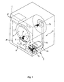
Figure 1 schematically shows a laundry dryer according to the present invention; -
Figure 2 schematically shows a detail of a dewatering unit used in the dryer offigure 1 ; -
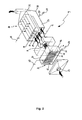
Figure 3 schematically shows a second embodiment of a ionization section; - With reference to
figure 1 , a laundry dryer according to the invention comprise acabinet 1 within which it is rotatably mounted a drum 2 defining achamber 4 adapted to receive articles 3 to be dried. Anair circuit 5 is provided for recirculating cyclically drying air through thechamber 4. An intake manifold 6 extracts a moist airflow from thechamber 4 and drives it through afilter 7 where lint and/or fluff are trapped. Moist air fromchamber 4 is extracted by afan 8 placed in theair circuit 5. After being filtered, air from thechamber 4 is passed through a dewatering unit 9 in which moisture grade in the moist airflow is progressively reduced. - Said dewatering unit 9 comprises a
ionization section 10 provided for maintaining a corona electric discharge that electrically charges water droplets dispersed in the moist airflow promoting their precipitation, thereby causing the airflow to be dried. - According to a first embodiment shown in greater detail in
figure 2 , theionization section 10 comprises corona discharge means 11 comprising a grid-like cathode 12 facing a moist air inlet opening 13 so as to be invested by the moist airflow coming from thedrying chamber 4. Cathode 12 is provided with a plurality of wire tips 14 serving for concentration of electric field and reduction of discharge ignition voltage. Cathode 12 is powered by suitable high voltage generating means 15. Anode is performed by grounded walls of theair circuit 5. Water extracted from the moist airflow is collected in a bottom part 16 of theionization section 10 and drained by atube 17 and pumping means 18. Said water is stored in a compartment 19 (seefigure 1 ) that must be periodically emptied by a user. - In
figure 3 it is shown a second embodiment of aionization section 210 to be used in a dewatering unit 9. Theionization section 210 comprise afirst bottom compartment 220 having an air inlet opening 213 for receiving moist air from thechamber 4 and a second upper compartment 221 (electric discharge compartment).Compartments aperture 222 on which amesh structure 223 is mounted. Corona discharge means 211 are provided and comprise acathode 212, in the form of awire 224 which is mounted in and extend within thedischarge compartment 221 for electrically charging water droplets dispersed in the moist airflow entering thebottom compartment 220, causing the airflow to be dried.Wire 224 is displaced so as to face themesh structure 223 and it is powered by suitable high voltage generating means 15. - A
ionization section 210 can be used in the laundry dryer shown infigure 1 as alternative to thefirst embodiment 10 depicted therein. - A
fan 8 is preferably placed downstream of theionization section air circuit 5.Fan 8 can be of axial or centrifugal type according to the design needs. - In order to improve water removal from the moist airflow, a laundry dryer according to the present invention can be provided with a dewatering unit 9 further comprising a
precipitation section 25 shown infigures 1 and, in grater detail, also infigure 2 . - A
precipitation section 25 is displaced downstream of theionization section fan 8.Precipitation section 25 receives air exiting theionization section Precipitation section 25 is provided with electric field generating means 26 comprising a plurality ofplates plates 28 are powered by suitable high-voltage generating means 15 and form a plurality of cathodes, while a second group ofplates 27 are grounded and form a plurality of anodes.Plates cathode plate 28 is spaced apart and parallel to at least aanode plate 27.Plates ionization section plates ionization section grounded plates 27. Precipitated water is collected in abottom portion 33 of theprecipitation section 25 and it is drained by atube 17 and pumping means 18 that can be the same used for draining water from theionization section precipitation section 25 is stored in a compartment 19 (seefigure 1 ) that must be periodically emptied by a user. - Dewatered air exiting the
precipitation section 25 is received by amanifold 31 that drives the air to a rear bulkhead 32 (seefigure 1 ) having air diffusion means for introducing air inside thechamber 4. - The use of a
precipitation section 25 may be optional and reserved for dryers where the amount of moisture in the airflow is very high. In case theprecipitation section 25 is not used,manifold 31 receives air discharged by theionization section bulkhead 32. In case theprecipitation section 25 is used, the latter can be displaced just downstream of theionization section precipitation section 25, afan 8 is mounted. - The air circulation within the
circuit 5 continues cyclically without exhausting air outside the appliance until the drying process is completed. Heating means of known type (not shown in the drawings) are provided in theair circuit 5 for heating the airflow circulating therein. - According to experimental results it has been found that in a moist airflow having a relative humidity grade grater than 100% the humidity grade is reduced up to 70% in about 3 minutes when the
ionization section 10, depicted infigures 1 and2 , is used and theprecipitation section 25 is inactive, i.e. allplates precipitation section 25 inactive, experiments made with use of aionization section 210 of the type depicted infigure 3 have shown that the humidity grade is reduced up to 73% in about 5 minutes. With the same type ofionization section 210, when theprecipitation section 25 is turned on (plates 28 are powered by a high voltage generating means 15), the humidity grade is reduced to about 62% in about 7 minutes. - The first embodiment of the
ionization section 10 illustrated infigures 1 and2 has shown a great efficiency in charging the water droplet dispersed in the moist airflow, while thesecond embodiment 210 depicted infigure 3 provides better discharge stability, higher electric strength and lower air flow disturbance. - Conclusively, the present invention allows a laundry dryer to efficiently remove water from a moist airflow by means of a compact and reliable dewatering device. The latter has a size which is smaller than that of a condenser normally used for a laundry dryer of known type and therefore the inner volume of a laundry cabinet can be used for displacing the appliance components in a more rationalized manner.
- It can also be stated that performances of a laundry dryer according to the invention are improved compared to laundry dryers of known type both considering the amount of moisture removed by the appliance both in term of power consuming.
Claims (10)
- Laundry dryer comprising a chamber (4) for receiving articles to be dried, an air circuit (5) for recirculating cyclically drying air through said chamber (4) and a dewatering unit (9) for reducing moisture content in moist airflow exiting said chamber (4) characterised in that said dewatering unit (9) comprises a ionization section (10, 210) for electrical charging water dispersed in said airflow and water exhausting means (17, 18).
- Laundry dryer according to claim 1 wherein said ionization section (10) is placed in the air circuit (5) downstream of said chamber (4).
- Laundry dryer according to claim 1 or 2 wherein said ionization section (10, 210) comprises corona discharge means (11, 211).
- Laundry dryer according to claim 3 wherein said corona discharge means (11) comprises a grid-like cathode (12) arranged so as to intercept the moist airflow, said grid-like cathode (12) being provided with a plurality of wire tips (14).
- Laundry dryer according to claim 3 wherein said corona discharge means (211) comprise a discharge compartment (221) separated from said airflow by a mesh structure (223) and further comprise a wire cathode (224) contained in said compartment (221) and facing said mesh structure (223).
- Laundry dryer according to any preceding claim wherein said dewatering unit (9) further comprises a water precipitation section (25) displaced downstream of said ionization section (10, 210) provided with electric field generating means (26).
- Laundry dryer according to claim 6 wherein said electric field generating means (26) comprise a plurality of alternately arranged grounded and high-potential plates (27, 28).
- Laundry dryer according to claim 7 wherein said plurality of plates (27, 28) are spaced apart and parallel one another forming a plurality of channels (29) adapted to receive said moist airflow.
- Laundry dryer according to any of claims 6 to 8 wherein said precipitation section (25) comprises water exhausting means (17, 18).
- Laundry dryer according to any preceding claim wherein said water exhausting means (17, 18) comprises a tube (17) and pumping means (18).
Applications Claiming Priority (1)
| Application Number | Priority Date | Filing Date | Title |
|---|---|---|---|
| EP07117158A EP2042641A1 (en) | 2007-09-25 | 2007-09-25 | Laundry dryer |
Related Parent Applications (1)
| Application Number | Title | Priority Date | Filing Date |
|---|---|---|---|
| EP07117158.1 Division | 2007-09-25 |
Publications (1)
| Publication Number | Publication Date |
|---|---|
| EP2423374A1 true EP2423374A1 (en) | 2012-02-29 |
Family
ID=39100068
Family Applications (2)
| Application Number | Title | Priority Date | Filing Date |
|---|---|---|---|
| EP07117158A Withdrawn EP2042641A1 (en) | 2007-09-25 | 2007-09-25 | Laundry dryer |
| EP11187915A Withdrawn EP2423374A1 (en) | 2007-09-25 | 2007-09-25 | Laundry dryer |
Family Applications Before (1)
| Application Number | Title | Priority Date | Filing Date |
|---|---|---|---|
| EP07117158A Withdrawn EP2042641A1 (en) | 2007-09-25 | 2007-09-25 | Laundry dryer |
Country Status (2)
| Country | Link |
|---|---|
| EP (2) | EP2042641A1 (en) |
| RU (1) | RU2466228C2 (en) |
Families Citing this family (4)
| Publication number | Priority date | Publication date | Assignee | Title |
|---|---|---|---|---|
| JP7578947B2 (en) * | 2020-12-28 | 2024-11-07 | 青島海爾洗衣机有限公司 | Dryer |
| JP7578948B2 (en) * | 2020-12-28 | 2024-11-07 | 青島海爾洗衣机有限公司 | Dryer |
| JP2023095502A (en) * | 2021-12-24 | 2023-07-06 | 青島海爾洗衣机有限公司 | Dehumidifier and dryer |
| CN121161577A (en) * | 2024-06-19 | 2025-12-19 | 青岛海尔洗衣机有限公司 | Drying equipment |
Citations (4)
| Publication number | Priority date | Publication date | Assignee | Title |
|---|---|---|---|---|
| US5435837A (en) * | 1993-12-06 | 1995-07-25 | Lewis; Keith B. | Ion generation structure in environmental systems |
| JPH10118593A (en) * | 1996-10-16 | 1998-05-12 | Koasu Corp:Kk | Method and apparatus for removing, drying and sterilizing clothes and accessories for clean rooms |
| JP2004065427A (en) * | 2002-08-05 | 2004-03-04 | Matsushita Electric Ind Co Ltd | Washing machine |
| EP1445367A1 (en) * | 2001-11-08 | 2004-08-11 | Sharp Kabushiki Kaisha | Drying/washing machine |
Family Cites Families (3)
| Publication number | Priority date | Publication date | Assignee | Title |
|---|---|---|---|---|
| SU1533726A1 (en) * | 1987-11-20 | 1990-01-07 | Государственный Научно-Исследовательский И Проектный Институт Нефтяной И Газовой Промышленности Им.В.А.Муравленко | Electric dehydrator |
| SU1587093A1 (en) * | 1988-03-23 | 1990-08-23 | В.П.Алешин | Drying machine for linen |
| CA2116761A1 (en) * | 1994-03-01 | 1995-09-02 | Keith B. Lewis | Ion generation structure in environmental systems |
-
2007
- 2007-09-25 EP EP07117158A patent/EP2042641A1/en not_active Withdrawn
- 2007-09-25 EP EP11187915A patent/EP2423374A1/en not_active Withdrawn
-
2008
- 2008-09-24 RU RU2008138092/12A patent/RU2466228C2/en not_active IP Right Cessation
Patent Citations (4)
| Publication number | Priority date | Publication date | Assignee | Title |
|---|---|---|---|---|
| US5435837A (en) * | 1993-12-06 | 1995-07-25 | Lewis; Keith B. | Ion generation structure in environmental systems |
| JPH10118593A (en) * | 1996-10-16 | 1998-05-12 | Koasu Corp:Kk | Method and apparatus for removing, drying and sterilizing clothes and accessories for clean rooms |
| EP1445367A1 (en) * | 2001-11-08 | 2004-08-11 | Sharp Kabushiki Kaisha | Drying/washing machine |
| JP2004065427A (en) * | 2002-08-05 | 2004-03-04 | Matsushita Electric Ind Co Ltd | Washing machine |
Also Published As
| Publication number | Publication date |
|---|---|
| RU2008138092A (en) | 2010-03-27 |
| RU2466228C2 (en) | 2012-11-10 |
| EP2042641A1 (en) | 2009-04-01 |
Similar Documents
| Publication | Publication Date | Title |
|---|---|---|
| EP2037034B1 (en) | Ductless type clothes drier | |
| US9803312B2 (en) | Dryer with heat pump | |
| US12221742B2 (en) | Tumble dryer | |
| EP2796615B1 (en) | Clothes dryer and method of cleaning evaporator in clothes dryer | |
| CN101981247A (en) | Laundry treating machine and control method of the same | |
| KR20090050620A (en) | Clothing processing device | |
| EP2042641A1 (en) | Laundry dryer | |
| EP3342922A1 (en) | Dryer | |
| KR100964692B1 (en) | Clothing processing device and control method | |
| KR20090050621A (en) | Clothing processing device | |
| CN211060569U (en) | Textile processing oven | |
| CN113957682A (en) | Condensing unit and clothes treatment equipment with same | |
| CN220489580U (en) | Dryer with tail gas recovery function | |
| EP3138952B1 (en) | A laundry dryer | |
| CN220236823U (en) | Water-steam separation device, dish washer inner bag and dish washer | |
| CN216171248U (en) | Drying device for excitation cabinet | |
| CN219557223U (en) | Shoe drier | |
| CN213740051U (en) | Jia ji cloth drying equipment | |
| KR20070013449A (en) | Clothes Dryer | |
| CN216338596U (en) | Drying device | |
| KR20100099432A (en) | Laundry treating machine | |
| EP4560067A1 (en) | Laundry device comprising a control | |
| CN212409305U (en) | Cloth is drip proof device for drying cylinder | |
| CN121629742A (en) | A garment processing device and its lint filtering assembly | |
| WO2025198554A1 (en) | A combined system including condenser dryer |
Legal Events
| Date | Code | Title | Description |
|---|---|---|---|
| AC | Divisional application: reference to earlier application |
Ref document number: 2042641 Country of ref document: EP Kind code of ref document: P |
|
| AK | Designated contracting states |
Kind code of ref document: A1 Designated state(s): AT BE BG CH CY CZ DE DK EE ES FI FR GB GR HU IE IS IT LI LT LU LV MC MT NL PL PT RO SE SI SK TR |
|
| PUAI | Public reference made under article 153(3) epc to a published international application that has entered the european phase |
Free format text: ORIGINAL CODE: 0009012 |
|
| 17P | Request for examination filed |
Effective date: 20120829 |
|
| STAA | Information on the status of an ep patent application or granted ep patent |
Free format text: STATUS: THE APPLICATION IS DEEMED TO BE WITHDRAWN |
|
| 18D | Application deemed to be withdrawn |
Effective date: 20150331 |
|
| R18D | Application deemed to be withdrawn (corrected) |
Effective date: 20150401 |