EP2423301A1 - Cell isolation apparatus - Google Patents
Cell isolation apparatus Download PDFInfo
- Publication number
- EP2423301A1 EP2423301A1 EP11178751A EP11178751A EP2423301A1 EP 2423301 A1 EP2423301 A1 EP 2423301A1 EP 11178751 A EP11178751 A EP 11178751A EP 11178751 A EP11178751 A EP 11178751A EP 2423301 A1 EP2423301 A1 EP 2423301A1
- Authority
- EP
- European Patent Office
- Prior art keywords
- chamber body
- cell isolation
- isolation apparatus
- tissue
- cell
- Prior art date
- Legal status (The legal status is an assumption and is not a legal conclusion. Google has not performed a legal analysis and makes no representation as to the accuracy of the status listed.)
- Granted
Links
Images




Classifications
-
- G—PHYSICS
- G01—MEASURING; TESTING
- G01N—INVESTIGATING OR ANALYSING MATERIALS BY DETERMINING THEIR CHEMICAL OR PHYSICAL PROPERTIES
- G01N1/00—Sampling; Preparing specimens for investigation
- G01N1/28—Preparing specimens for investigation including physical details of (bio-)chemical methods covered elsewhere, e.g. G01N33/50, C12Q
- G01N1/286—Preparing specimens for investigation including physical details of (bio-)chemical methods covered elsewhere, e.g. G01N33/50, C12Q involving mechanical work, e.g. chopping, disintegrating, compacting, homogenising
-
- C—CHEMISTRY; METALLURGY
- C12—BIOCHEMISTRY; BEER; SPIRITS; WINE; VINEGAR; MICROBIOLOGY; ENZYMOLOGY; MUTATION OR GENETIC ENGINEERING
- C12M—APPARATUS FOR ENZYMOLOGY OR MICROBIOLOGY; APPARATUS FOR CULTURING MICROORGANISMS FOR PRODUCING BIOMASS, FOR GROWING CELLS OR FOR OBTAINING FERMENTATION OR METABOLIC PRODUCTS, i.e. BIOREACTORS OR FERMENTERS
- C12M41/00—Means for regulation, monitoring, measurement or control, e.g. flow regulation
- C12M41/02—Means for regulation, monitoring, measurement or control, e.g. flow regulation of foam
-
- C—CHEMISTRY; METALLURGY
- C12—BIOCHEMISTRY; BEER; SPIRITS; WINE; VINEGAR; MICROBIOLOGY; ENZYMOLOGY; MUTATION OR GENETIC ENGINEERING
- C12M—APPARATUS FOR ENZYMOLOGY OR MICROBIOLOGY; APPARATUS FOR CULTURING MICROORGANISMS FOR PRODUCING BIOMASS, FOR GROWING CELLS OR FOR OBTAINING FERMENTATION OR METABOLIC PRODUCTS, i.e. BIOREACTORS OR FERMENTERS
- C12M45/00—Means for pre-treatment of biological substances
- C12M45/02—Means for pre-treatment of biological substances by mechanical forces; Stirring; Trituration; Comminuting
-
- C—CHEMISTRY; METALLURGY
- C12—BIOCHEMISTRY; BEER; SPIRITS; WINE; VINEGAR; MICROBIOLOGY; ENZYMOLOGY; MUTATION OR GENETIC ENGINEERING
- C12M—APPARATUS FOR ENZYMOLOGY OR MICROBIOLOGY; APPARATUS FOR CULTURING MICROORGANISMS FOR PRODUCING BIOMASS, FOR GROWING CELLS OR FOR OBTAINING FERMENTATION OR METABOLIC PRODUCTS, i.e. BIOREACTORS OR FERMENTERS
- C12M47/00—Means for after-treatment of the produced biomass or of the fermentation or metabolic products, e.g. storage of biomass
- C12M47/04—Cell isolation or sorting
-
- G—PHYSICS
- G01—MEASURING; TESTING
- G01N—INVESTIGATING OR ANALYSING MATERIALS BY DETERMINING THEIR CHEMICAL OR PHYSICAL PROPERTIES
- G01N1/00—Sampling; Preparing specimens for investigation
- G01N1/28—Preparing specimens for investigation including physical details of (bio-)chemical methods covered elsewhere, e.g. G01N33/50, C12Q
- G01N1/286—Preparing specimens for investigation including physical details of (bio-)chemical methods covered elsewhere, e.g. G01N33/50, C12Q involving mechanical work, e.g. chopping, disintegrating, compacting, homogenising
- G01N2001/2866—Grinding or homogeneising
Definitions
- the present invention relates to a cell isolation apparatus which is used in the field of clinics/research of regenerative medicine, or that of cell culture, and more particularly to a cell isolation apparatus which can isolate cells from tissue (body tissue) with a high survival rate.
- tissue is minced with a sharp blade, and the minced tissue is subjected to enzymatic treatment with collagenase or the like to digest the extracellular matrix, thereby obtaining isolated cells.
- the related-art technique in the enzymatic treatment with collagenase solution, procedures of enzymatic treatment and cell retrieving are repeated. Therefore, the related-art technique requires a very long time period.
- the related-art technique has further problems such as that the cell retrieving rate is dispersed because of differences in the mincing process with using a blade, the permeation rate in the enzymatic treatment, etc.
- a related-art tissue dissociation device in which tissue is dissociated by rotation includes a container having a sterile interior for holding the tissue to be dissociated and a liquid medium, and also a dissociation element, inside the container, for engaging the tissue to cause dissociation of the tissue.
- the device further includes a resistive element, inside the container, for resisting movement of the tissue in response to the engagement by the dissociation element.
- a powered tissue dissociation device includes a power source operatively connected to the dissociation element for causing the dissociation element to move into engagement with the tissue (see JP-T-2007-505631 ).
- the resistance provided by the resistive element allows the dissociation element to effectively dissociate the tissue, and hence cells collide with the resistive element, thereby causing the possibility that the survival rate of cells is lowered.
- It is another object of the invention is to provide a cell isolation apparatus in which the operation time period can be remarkably shortened.
- a cell isolation apparatus comprising: a chamber body which includes a chamber into which tissue is to be introduced; an isolation member which is moved in the chamber and which is to collide with the tissue to isolate a cell; and a controlling portion which controls an operation of the isolation member in the chamber body.
- the isolation member may include a plurality of blade members.
- the cell isolation apparatus may further include a liquid level sensor which detects a level of a solution in the chamber.
- the controlling portion may control the operation of the isolation member based on a result of detection by the liquid level sensor.
- the cell isolation apparatus may further include a temperature controlling unit which controls one of a temperature in the chamber body and a temperature of the cell isolation apparatus.
- the cell isolation apparatus may further include a liquid introducing portion which introduces liquid into the chamber body.
- the isolation member may include a shaft member, a plurality of blade members which are attached to the shaft member, and a supporting unit which supports the plurality of blade members in the shaft member.
- the shaft member may be rotated by a magnetic rotation driving portion which is not in contact with the isolation member.
- a bearing which receives the shaft member may be provided in the chamber body.
- Fig. 1 is an assembly perspective view a cell isolation apparatus of a first embodiment
- Fig. 2 is a view of an assembled state, as viewed from a lateral side.
- the cell isolation apparatus includes a cup-shaped chamber body 11, a lid member 12 for the chamber body 11, an isolation member 20, and a control device 30.
- the chamber body 11 has a chamber 13 into which tissue is to be introduced, and in which the isolation member 20 is moved.
- a step 14 is formed in the inner peripheral wall of an opening portion of the chamber body 11.
- a peripheral edge portion 15a of a lid plate 15 of the lid member 12 is butted against and placed on the step 14.
- a flange 16 is disposed in a lower portion of the chamber body 11 so that the cell isolation apparatus can be stably installed.
- the isolation member 20 includes: a shaft member 21 which is a rotation shaft; a plurality of blade members 22 which are coupled to the shaft member 21; and a supporting unit which supports the plurality of blade members 22 in the shaft member 21.
- Each of the blade members 22 is formed so as to be gradually narrowed in width as advancing from a basal portion 22a to a tip end portion 22b.
- the blade member 22 has a planar shape of an acute isosceles triangle. A blade is formed in one or both of the long sides. In the basal portion 22a, a hole 24 is opened in the thickness direction.
- a recess 25 which houses the basal portions 22a of the blade members 22 is formed in the vicinity of a lower end portion of the shaft member 21.
- a screw hole 25a is formed from the recess 25 into the shaft member 21 in the axial direction.
- four blade members 22 are alternately stacked on one another through spacers 26, and tip end portions 22b of two of the blade members are in direction separated by 180 degrees from those of the other two blade members.
- the blade members 22 which are stacked in this state are supported by screwing a screw 27 through the holes 24 of the blade members 22 and the spacers 26 into the screw hole 25a of the shaft member 21.
- the recess 25, the screw hole 25a, the spacers 26, and the screw 27 constitute a supporting unit which supports the plurality of blade members 22.
- the isolation member may include blade members 22 which are projected in directions separated by 90 degrees.
- An upper end portion of the shaft member 21 is formed as a rectangular columnar coupling portion 29 which is coupled to a bearing hole 34 coupled to a motor 33 of the control device 30.
- a through hole 17 through which the shaft member 21 is passed is formed in a middle portion of the lid member 12. The coupling portion 29 of the shaft member 21 is coupled to the bearing hole 34 through the through hole 17.
- a recess 18 which constitutes a bearing that receives a lower end portion 28 of the shaft member 21 is formed in a middle portion of the bottom surface of the chamber 13 of the chamber body 11.
- the lower end portion 28 of the shaft member 21 is rotatably supported by the recess 18.
- the blade members 22 are at positions which are slightly upward separated from the bottom surface of the chamber 13 of the chamber body 11, and, when rotated, collide with tissue so that the tissue can be adequately isolated.
- a hole 19 which constitutes a liquid introducing portion for introducing liquid into the chamber body 11 is formed.
- a lid piece 19A which is configured by an elastic member, and which, when pressed from the outside, is moved to cause the outside to communicate with the interior of the chamber body 11 through the hole 19 is disposed on the side of the interior of the chamber body 11.
- the control device 30 includes a controlling portion 31 which is configured by a CPU for controlling the cell isolation apparatus.
- An operating portion 32 including various keys and the like, and an I/O 35 are connected to the controlling portion 31.
- the motor 33, a rotation sensor 33A, a temperature element 36 including a temperature sensor, and a liquid level sensor 37 are connected to the I/O 35.
- the rotation sensor 33A is connected to the motor 33, detects the number of rotations and the rotational direction, and transmits them to the controlling portion 31.
- the temperature element 36 is disposed on the outer or inner wall surface of the chamber body 11, and functions as a temperature controlling unit which transmits the temperature to the controlling portion 31, and which performs a heating or cooling operation to control the temperature in response to the control by the controlling portion 31.
- the liquid level sensor 37 is attached to a surface of the lid member 12 on the interior side of the chamber body 11, detects the level data (the distance from the attached position to the liquid level) of the liquid level on the side bottom surface of the chamber body 11, and transmits the data to the controlling portion 31.
- the thus configured cell isolation apparatus can perform the cell isolation process in the following manner.
- a predetermined amount of an enzyme solution which is previously heated to the activation temperature is introduced into the chamber body 11.
- tissue extracted from a living body is loaded into the chamber body 11.
- the isolation member 20, the lid member 12, and the control device 30 are set to predetermined positions to assemble the cell isolation apparatus.
- the stirring conditions (the number of rotations, the rotating method, the time, and the like), and the temperature conditions are set through the operating portion 32, and a key for starting the process is operated.
- right rotation for aa sec., stop for bb sec., left rotation for cc sec., and the like are set.
- the time period for repeating the method is input.
- the controlling portion 31 controls the rotation of the motor 33 in accordance with the above-described input, and the temperature element 36 in accordance with the temperature conditions to maintain a predetermined temperature.
- the adequate stirring state is realized by, for example, lowering the number of rotations, and cells are isolated with a high survival rate.
- the turbid solution which has been processed as described above is taken out from the chamber body 11, and then subjected to the mesh process to take out isolated cells.
- the main components of the cell isolation apparatus are a cup-shaped chamber body 11A, a lid member 12A of the chamber body 11A, an isolation member 20A, and a control device 30A.
- Fig. 5A is an assembly perspective view.
- a shaft member 21A of the isolation member 20A has a flat columnar shape, and includes a small columnar shaft 51 which is projected from the lower surface.
- a bearing 52 which rotatably supports the shaft 51, and which is configured by a bottomed hole is formed in a middle portion of the bottom surface of a chamber 13 of the chamber body 11A.
- Fig. 7 is an assembly perspective view of the isolation member 20A. Openings 53 into which the basal portions 22a of the blade members 22 are inserted are formed at positions in a side portion of the shaft member 21A which are paired in the diameter direction. A screw hole 54 which is not passed through the surface is formed in a middle portion of a top portion of the shaft member 21A.
- Two blade members 22 are inserted into each of the openings 53 while being stacked on each other through the spacer 26.
- a hole 55 which is passed through the surface is formed in a middle portion of a lower portion of the shaft member 21A.
- the screw 27 is passed through the holes 24 via the hole 55 to be screwed with the hole 24, thereby constituting a supporting unit which supports the plurality of blade members 22.
- the isolation member may include blade members 22 which are projected in directions separated by 90 degrees.
- a stirrer driving device 61 is disposed below the chamber body 11A.
- a configuration where the stirrer driving device 61 is incorporated in the control device 30A is shown.
- the components other than the stirrer driving device 61 may be disposed at other positions.
- a coupling groove 62 for the chamber body 11A is formed on the case of the control device 30A, and fitted with a projection (not shown) of the chamber body 11A to be fixed thereto.
- the control device 30A is configured in the same manner as that of the first embodiment except that a controlling portion 31A controls the stirrer driving device 61 to control the rotation of the shaft member 21A which constitutes a rotor of a stirrer. According to the configuration, the shaft member 21A is rotated as a rotor by the stirrer driving device 61 that is a magnetic rotation driving portion which is not in contact with the isolation member 20A.
- the thus configured cell isolation apparatus can perform the cell isolation process in the following manner.
- a predetermined amount of an enzyme solution which is previously heated to the activation temperature is introduced into the chamber body 11A.
- tissue extracted from a living body is loaded into the chamber body 11A.
- the isolation member 20A, the lid member 12A, and the control device 30A are set to predetermined positions to assemble the cell isolation apparatus.
- the chamber 13 of the chamber body 11A is isolated from the outside, and can be set to be in a hermetically-sealed state. As a result, the risk that unwanted substances enter the chamber body 11A is eliminated, and there is no possibility that the liquid or the like in the chamber body 11A is splashed out to the outside.
- the stirring conditions and the temperature conditions are set through the operating portion 32, and a key for starting the process is operated, the process is performed under control of the controlling portion 31A, and the turbid solution is taken out from the chamber body 11A, and then subjected to the mesh process to take out isolated cells.
- cells were isolated from tissue.
- cells which were obtained by a related-art technique, and those which were obtained by the invention were compared with each other.
- Cardiomyocyte tissue of a neonate rat was used as the tissue.
- the number of rotations was 200 rpm, and an intermittent operation of rotation for 0.5 sec. and stop of 1 sec. was performed for 30 min. A mesh of 40 ⁇ m was used.
- Fig. 9 shows a graph in which the mean value and the standard deviation of acquired amounts of cells that were acquired from the same amount of tissue were obtained by the technique of the invention and a related-art technique.
- Fig. 12 shows the mean value and the standard deviation in the form of numerals. As apparent from Figs. 9 and 12 , the technique of the invention can obtain cells with very high efficiency.
- Fig. 10 shows a graph in which the mean value and the standard deviation of the CK activity value per unit number of cells immediately after acquisition of isolated cells were obtained by the technique of the invention and a related-art technique.
- Fig. 12 shows the mean value and the standard deviation in the form of numerals.
- the rate of cardiomyocyte cells per unit number of cells can be known.
- damage to cells can be reduced, and therefore it is known that living cardiomyocyte cells can be easily acquired in a more excellent manner as compared with the related-art technique.
- Fig. 11 shows a graph in which the mean value and the standard deviation of the survival rate of cells on the fourth day after acquisition of isolated cells were obtained by the technique of the invention and a related-art technique.
- Fig. 12 shows the mean value and the standard deviation in the form of numerals. As apparent from Figs. 11 and 12 , it is known that, in the technique of the invention, less damage is imparted to cells, and cells can be acquired with a higher survival rate as compared with the related-art technique.
- the cell isolation apparatus includes the chamber body having the chamber into which tissue is to be introduced, and in which the isolation member is moved, and the operation of the isolation member in the chamber body is controlled. Therefore, the survival rate of cells can be enhanced.
- the isolation member has a plurality of blade members, and hence isolation of cells can be efficiently performed.
- the cell isolation apparatus includes the liquid level sensor which detects the level of the solution in the chamber, and the controlling portion controls the operation of the isolation member based on a result of detection by the liquid level sensor. Therefore, stirring can be adequately performed without causing the solution in the chamber to bubble, and the survival rate of cells can be enhanced.
- the cell isolation apparatus includes the temperature controlling unit which controls the temperature in the chamber body, or that of the apparatus. Therefore, activation/deactivation of enzyme can be controlled.
- the cell isolation apparatus includes the liquid introducing portion for introducing liquid into the chamber body.
- necessary liquid introduction such as introduction of an inhibitor can be performed.
- the isolation member includes the shaft member, the plurality of blade members which are coupled to the shaft member, and the supporting unit which supports the plurality of blade members in the shaft member. Therefore, an adequate stirred state can be realized by necessary rotation, and the survival rate of cells can be enhanced.
- the shaft member is rotated by the magnetic rotation driving portion which is not in contact with the isolation member. Therefore, stirring can be performed while the chamber body is covered by a lid, and there is an effect that it is possible to prevent unwanted substances from entering the chamber body from the outside, and also to prevent the outside from being contaminated.
- the bearing for receiving the rotation shaft is formed in the chamber body. Therefore, stable rotation can be ensured in the chamber body.
Landscapes
- Life Sciences & Earth Sciences (AREA)
- Health & Medical Sciences (AREA)
- Engineering & Computer Science (AREA)
- Chemical & Material Sciences (AREA)
- Organic Chemistry (AREA)
- Zoology (AREA)
- Wood Science & Technology (AREA)
- Bioinformatics & Cheminformatics (AREA)
- General Health & Medical Sciences (AREA)
- Biotechnology (AREA)
- Biochemistry (AREA)
- Genetics & Genomics (AREA)
- Biomedical Technology (AREA)
- General Engineering & Computer Science (AREA)
- Microbiology (AREA)
- Sustainable Development (AREA)
- Molecular Biology (AREA)
- Analytical Chemistry (AREA)
- Physics & Mathematics (AREA)
- Immunology (AREA)
- Mechanical Engineering (AREA)
- Pathology (AREA)
- General Physics & Mathematics (AREA)
- Cell Biology (AREA)
- Apparatus Associated With Microorganisms And Enzymes (AREA)
- Micro-Organisms Or Cultivation Processes Thereof (AREA)
Abstract
Description
- The present invention relates to a cell isolation apparatus which is used in the field of clinics/research of regenerative medicine, or that of cell culture, and more particularly to a cell isolation apparatus which can isolate cells from tissue (body tissue) with a high survival rate.
- In order to obtain living cells, tissue is minced with a sharp blade, and the minced tissue is subjected to enzymatic treatment with collagenase or the like to digest the extracellular matrix, thereby obtaining isolated cells.
- In the related-art technique, in the enzymatic treatment with collagenase solution, procedures of enzymatic treatment and cell retrieving are repeated. Therefore, the related-art technique requires a very long time period. The related-art technique has further problems such as that the cell retrieving rate is dispersed because of differences in the mincing process with using a blade, the permeation rate in the enzymatic treatment, etc.
- A related-art tissue dissociation device in which tissue is dissociated by rotation includes a container having a sterile interior for holding the tissue to be dissociated and a liquid medium, and also a dissociation element, inside the container, for engaging the tissue to cause dissociation of the tissue. The device further includes a resistive element, inside the container, for resisting movement of the tissue in response to the engagement by the dissociation element. In the device, relative motion between the dissociation element and the resistive element, and resistance provided by the resistive element as a result of the motion allow the dissociation element to effectively dissociate the tissue. A powered tissue dissociation device includes a power source operatively connected to the dissociation element for causing the dissociation element to move into engagement with the tissue (see
JP-T-2007-505631 - In the related-art device, however, the resistance provided by the resistive element allows the dissociation element to effectively dissociate the tissue, and hence cells collide with the resistive element, thereby causing the possibility that the survival rate of cells is lowered.
- It is therefore an object of the invention to provide a cell isolation apparatus which can isolate cells from tissue (body tissue) with a high survival rate.
- It is another object of the invention is to provide a cell isolation apparatus in which the operation time period can be remarkably shortened.
- In order to achieve the object, according to the invention, there is provided a cell isolation apparatus comprising: a chamber body which includes a chamber into which tissue is to be introduced; an isolation member which is moved in the chamber and which is to collide with the tissue to isolate a cell; and a controlling portion which controls an operation of the isolation member in the chamber body.
- The isolation member may include a plurality of blade members.
- The cell isolation apparatus may further include a liquid level sensor which detects a level of a solution in the chamber. The controlling portion may control the operation of the isolation member based on a result of detection by the liquid level sensor.
- The cell isolation apparatus may further include a temperature controlling unit which controls one of a temperature in the chamber body and a temperature of the cell isolation apparatus.
- The cell isolation apparatus may further include a liquid introducing portion which introduces liquid into the chamber body.
- The isolation member may include a shaft member, a plurality of blade members which are attached to the shaft member, and a supporting unit which supports the plurality of blade members in the shaft member.
- The shaft member may be rotated by a magnetic rotation driving portion which is not in contact with the isolation member.
- A bearing which receives the shaft member may be provided in the chamber body.
-
-
Fig. 1 is an assembly perspective view showing a first embodiment of the cell isolation apparatus of the invention. -
Fig. 2 is a view showing the first embodiment of the cell isolation apparatus of the invention, as viewed from a lateral side. -
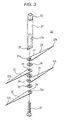
Fig. 3 is an assembly perspective view showing an isolation member in the first embodiment of the cell isolation apparatus of the invention. -
Fig. 4 is a perspective view showing a modification of the isolation member in the first embodiment of the cell isolation apparatus of the invention. -
Fig. 5A is an assembly perspective view showing a second embodiment of the cell isolation apparatus of the invention, andFig. 5B is a view showing the second embodiment of the cell isolation apparatus of the invention, as viewed from a lateral side. -
Fig. 6 is a view showing the second embodiment of the cell isolation apparatus of the invention, as viewed from a lateral side. -
Fig. 7 is an assembly perspective view showing an isolation member in the second embodiment of the cell isolation apparatus of the invention. -
Fig. 8 is a perspective view showing a modification of the isolation member in the second embodiment of the cell isolation apparatus of the invention. -
Fig. 9 is a view showing a graph of the acquired amount of cells which were obtained by the technique of the invention and a related-art technique. -
Fig. 10 is a view showing a graph of the activity value of creatin kinase (CK) per unit number of cells immediately after acquisition of isolated cells which were obtained by the technique of the invention and a related-art technique. -
Fig. 11 is a view showing a graph of the survival rate of cells on the fourth day after acquisition of isolated cells which were obtained by the technique of the invention and a related-art technique. -
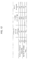
Fig. 12 is a view showing the graphs ofFigs. 9 to 11 by means of numerals. - Hereinafter, embodiments of the cell isolation apparatus of the invention will be described with reference to the accompanying drawings. In the figures, the identical components are denoted by the same reference numerals, and duplicated description will be omitted.
Fig. 1 is an assembly perspective view a cell isolation apparatus of a first embodiment, andFig. 2 is a view of an assembled state, as viewed from a lateral side. The cell isolation apparatus includes a cup-shaped chamber body 11, alid member 12 for thechamber body 11, anisolation member 20, and acontrol device 30. - The
chamber body 11 has achamber 13 into which tissue is to be introduced, and in which theisolation member 20 is moved. Astep 14 is formed in the inner peripheral wall of an opening portion of thechamber body 11. Aperipheral edge portion 15a of alid plate 15 of thelid member 12 is butted against and placed on thestep 14. Aflange 16 is disposed in a lower portion of thechamber body 11 so that the cell isolation apparatus can be stably installed. - As shown in
Fig. 3 , theisolation member 20 includes: ashaft member 21 which is a rotation shaft; a plurality ofblade members 22 which are coupled to theshaft member 21; and a supporting unit which supports the plurality ofblade members 22 in theshaft member 21. Each of theblade members 22 is formed so as to be gradually narrowed in width as advancing from abasal portion 22a to atip end portion 22b. Theblade member 22 has a planar shape of an acute isosceles triangle. A blade is formed in one or both of the long sides. In thebasal portion 22a, ahole 24 is opened in the thickness direction. - A
recess 25 which houses thebasal portions 22a of theblade members 22 is formed in the vicinity of a lower end portion of theshaft member 21. Ascrew hole 25a is formed from therecess 25 into theshaft member 21 in the axial direction. In the embodiment, fourblade members 22 are alternately stacked on one another throughspacers 26, and tipend portions 22b of two of the blade members are in direction separated by 180 degrees from those of the other two blade members. Theblade members 22 which are stacked in this state are supported by screwing ascrew 27 through theholes 24 of theblade members 22 and thespacers 26 into thescrew hole 25a of theshaft member 21. As described above, therecess 25, thescrew hole 25a, thespacers 26, and thescrew 27 constitute a supporting unit which supports the plurality ofblade members 22. - The above-described number and projected directions of the
blade members 22 are mere examples. As shown inFig. 4 , therefore, the isolation member may includeblade members 22 which are projected in directions separated by 90 degrees. - An upper end portion of the
shaft member 21 is formed as a rectangularcolumnar coupling portion 29 which is coupled to abearing hole 34 coupled to amotor 33 of thecontrol device 30. A throughhole 17 through which theshaft member 21 is passed is formed in a middle portion of thelid member 12. Thecoupling portion 29 of theshaft member 21 is coupled to thebearing hole 34 through thethrough hole 17. - A
recess 18 which constitutes a bearing that receives alower end portion 28 of theshaft member 21 is formed in a middle portion of the bottom surface of thechamber 13 of thechamber body 11. In a state where the apparatus is assembled, thelower end portion 28 of theshaft member 21 is rotatably supported by therecess 18. In this state, theblade members 22 are at positions which are slightly upward separated from the bottom surface of thechamber 13 of thechamber body 11, and, when rotated, collide with tissue so that the tissue can be adequately isolated. - In the
lid member 12, ahole 19 which constitutes a liquid introducing portion for introducing liquid into thechamber body 11 is formed. In thehole 19, alid piece 19A which is configured by an elastic member, and which, when pressed from the outside, is moved to cause the outside to communicate with the interior of thechamber body 11 through thehole 19 is disposed on the side of the interior of thechamber body 11. When the action of enzyme is to be stopped, therefore, a dropper into which an inhibitor or the like is sucked is inserted into thehole 19 that is normally closed by thelid piece 19A, and necessary liquid introduction can be performed. - The
control device 30 includes a controllingportion 31 which is configured by a CPU for controlling the cell isolation apparatus. An operatingportion 32 including various keys and the like, and an I/O 35 are connected to the controllingportion 31. Themotor 33, arotation sensor 33A, atemperature element 36 including a temperature sensor, and aliquid level sensor 37 are connected to the I/O 35. - The
rotation sensor 33A is connected to themotor 33, detects the number of rotations and the rotational direction, and transmits them to the controllingportion 31. Thetemperature element 36 is disposed on the outer or inner wall surface of thechamber body 11, and functions as a temperature controlling unit which transmits the temperature to the controllingportion 31, and which performs a heating or cooling operation to control the temperature in response to the control by the controllingportion 31. For example, theliquid level sensor 37 is attached to a surface of thelid member 12 on the interior side of thechamber body 11, detects the level data (the distance from the attached position to the liquid level) of the liquid level on the side bottom surface of thechamber body 11, and transmits the data to the controllingportion 31. - The thus configured cell isolation apparatus can perform the cell isolation process in the following manner. A predetermined amount of an enzyme solution which is previously heated to the activation temperature is introduced into the
chamber body 11. Next, tissue extracted from a living body is loaded into thechamber body 11. Theisolation member 20, thelid member 12, and thecontrol device 30 are set to predetermined positions to assemble the cell isolation apparatus. The stirring conditions (the number of rotations, the rotating method, the time, and the like), and the temperature conditions are set through the operatingportion 32, and a key for starting the process is operated. In the rotating method, right rotation for aa sec., stop for bb sec., left rotation for cc sec., and the like are set. The time period for repeating the method is input. - The controlling
portion 31 controls the rotation of themotor 33 in accordance with the above-described input, and thetemperature element 36 in accordance with the temperature conditions to maintain a predetermined temperature. In the case where variation for a predetermined time period exceeds a predetermined threshold as a result of the detection by theliquid level sensor 37, the adequate stirring state is realized by, for example, lowering the number of rotations, and cells are isolated with a high survival rate. - The turbid solution which has been processed as described above is taken out from the
chamber body 11, and then subjected to the mesh process to take out isolated cells. - Next, the configuration of a cell isolation apparatus of a second embodiment will be described. The main components of the cell isolation apparatus are a cup-shaped
chamber body 11A, alid member 12A of thechamber body 11A, anisolation member 20A, and acontrol device 30A. -
Fig. 5A is an assembly perspective view. Ashaft member 21A of theisolation member 20A has a flat columnar shape, and includes a smallcolumnar shaft 51 which is projected from the lower surface. A bearing 52 which rotatably supports theshaft 51, and which is configured by a bottomed hole is formed in a middle portion of the bottom surface of achamber 13 of thechamber body 11A. -
Fig. 7 is an assembly perspective view of theisolation member 20A.Openings 53 into which thebasal portions 22a of theblade members 22 are inserted are formed at positions in a side portion of theshaft member 21A which are paired in the diameter direction. Ascrew hole 54 which is not passed through the surface is formed in a middle portion of a top portion of theshaft member 21A. - Two
blade members 22 are inserted into each of theopenings 53 while being stacked on each other through thespacer 26. Ahole 55 which is passed through the surface is formed in a middle portion of a lower portion of theshaft member 21A. In the total of fourblade members 22 which are inserted through the twoopenings 53, thescrew 27 is passed through theholes 24 via thehole 55 to be screwed with thehole 24, thereby constituting a supporting unit which supports the plurality ofblade members 22. - The above-described number and projected directions of the
blade members 22 are mere examples. As shown inFig. 8 , therefore, the isolation member may includeblade members 22 which are projected in directions separated by 90 degrees. - As shown in
Fig. 5B andFig. 6 , astirrer driving device 61 is disposed below thechamber body 11A. In the embodiment, a configuration where thestirrer driving device 61 is incorporated in thecontrol device 30A is shown. However, the components other than thestirrer driving device 61 may be disposed at other positions. Acoupling groove 62 for thechamber body 11A is formed on the case of thecontrol device 30A, and fitted with a projection (not shown) of thechamber body 11A to be fixed thereto. - The
control device 30A is configured in the same manner as that of the first embodiment except that a controllingportion 31A controls thestirrer driving device 61 to control the rotation of theshaft member 21A which constitutes a rotor of a stirrer. According to the configuration, theshaft member 21A is rotated as a rotor by thestirrer driving device 61 that is a magnetic rotation driving portion which is not in contact with theisolation member 20A. - The thus configured cell isolation apparatus can perform the cell isolation process in the following manner. A predetermined amount of an enzyme solution which is previously heated to the activation temperature is introduced into the
chamber body 11A. Next, tissue extracted from a living body is loaded into thechamber body 11A. Theisolation member 20A, thelid member 12A, and thecontrol device 30A are set to predetermined positions to assemble the cell isolation apparatus. In this state, thechamber 13 of thechamber body 11A is isolated from the outside, and can be set to be in a hermetically-sealed state. As a result, the risk that unwanted substances enter thechamber body 11A is eliminated, and there is no possibility that the liquid or the like in thechamber body 11A is splashed out to the outside. - In the same manner as the first embodiment, the stirring conditions and the temperature conditions are set through the operating
portion 32, and a key for starting the process is operated, the process is performed under control of the controllingportion 31A, and the turbid solution is taken out from thechamber body 11A, and then subjected to the mesh process to take out isolated cells. - By using the cell isolation apparatus of the above-described first or second embodiment, cells were isolated from tissue. In this case, cells which were obtained by a related-art technique, and those which were obtained by the invention were compared with each other. Cardiomyocyte tissue of a neonate rat was used as the tissue. With respect to the stirring conditions, the number of rotations was 200 rpm, and an intermittent operation of rotation for 0.5 sec. and stop of 1 sec. was performed for 30 min. A mesh of 40 µm was used.
-
Fig. 9 shows a graph in which the mean value and the standard deviation of acquired amounts of cells that were acquired from the same amount of tissue were obtained by the technique of the invention and a related-art technique.Fig. 12 shows the mean value and the standard deviation in the form of numerals. As apparent fromFigs. 9 and12 , the technique of the invention can obtain cells with very high efficiency. -
Fig. 10 shows a graph in which the mean value and the standard deviation of the CK activity value per unit number of cells immediately after acquisition of isolated cells were obtained by the technique of the invention and a related-art technique.Fig. 12 shows the mean value and the standard deviation in the form of numerals. As apparent fromFigs. 10 and12 , the rate of cardiomyocyte cells per unit number of cells can be known. In the technique of the invention, damage to cells can be reduced, and therefore it is known that living cardiomyocyte cells can be easily acquired in a more excellent manner as compared with the related-art technique. -
Fig. 11 shows a graph in which the mean value and the standard deviation of the survival rate of cells on the fourth day after acquisition of isolated cells were obtained by the technique of the invention and a related-art technique.Fig. 12 shows the mean value and the standard deviation in the form of numerals. As apparent fromFigs. 11 and12 , it is known that, in the technique of the invention, less damage is imparted to cells, and cells can be acquired with a higher survival rate as compared with the related-art technique. - According to an aspect of the invention, the cell isolation apparatus includes the chamber body having the chamber into which tissue is to be introduced, and in which the isolation member is moved, and the operation of the isolation member in the chamber body is controlled. Therefore, the survival rate of cells can be enhanced.
- According to an aspect of the invention, the isolation member has a plurality of blade members, and hence isolation of cells can be efficiently performed.
- According to an aspect of the invention, the cell isolation apparatus includes the liquid level sensor which detects the level of the solution in the chamber, and the controlling portion controls the operation of the isolation member based on a result of detection by the liquid level sensor. Therefore, stirring can be adequately performed without causing the solution in the chamber to bubble, and the survival rate of cells can be enhanced.
- According to an aspect of the invention, the cell isolation apparatus includes the temperature controlling unit which controls the temperature in the chamber body, or that of the apparatus. Therefore, activation/deactivation of enzyme can be controlled.
- According to an aspect of the invention, the cell isolation apparatus includes the liquid introducing portion for introducing liquid into the chamber body. When the action of enzyme is to be stopped, therefore, necessary liquid introduction such as introduction of an inhibitor can be performed.
- According to an aspect of the invention, the isolation member includes the shaft member, the plurality of blade members which are coupled to the shaft member, and the supporting unit which supports the plurality of blade members in the shaft member. Therefore, an adequate stirred state can be realized by necessary rotation, and the survival rate of cells can be enhanced.
- According to an aspect of the invention, the shaft member is rotated by the magnetic rotation driving portion which is not in contact with the isolation member. Therefore, stirring can be performed while the chamber body is covered by a lid, and there is an effect that it is possible to prevent unwanted substances from entering the chamber body from the outside, and also to prevent the outside from being contaminated.
- According to an aspect of the invention, the bearing for receiving the rotation shaft is formed in the chamber body. Therefore, stable rotation can be ensured in the chamber body.
Claims (8)
- A cell isolation apparatus comprising:a chamber body which includes a chamber into which tissue is to be introduced;an isolation member which is moved in the chamber and which is to collide with the tissue to isolate a cell; anda controlling portion which controls an operation of the isolation member in the chamber body.
- The cell isolation apparatus according to claim 1, wherein the isolation member includes a plurality of blade members.
- The cell isolation apparatus according to claim 1, further comprising:a liquid level sensor which detects a level of a solution in the chamber, whereinthe controlling portion controls the operation of the isolation member based on a result of detection by the liquid level sensor.
- The cell isolation apparatus according to claim 1, further comprising:a temperature controlling unit which controls one of a temperature in the chamber body and a temperature of the cell isolation apparatus.
- The cell isolation apparatus according to claim 1, further comprising:a liquid introducing portion which introduces liquid into the chamber body.
- The cell isolation apparatus according to claim 1, wherein
the isolation member includes a shaft member, a plurality of blade members which are attached to the shaft member, and a supporting unit which supports the plurality of blade members in the shaft member. - The cell isolation apparatus according to claim 6, wherein the shaft member is rotated by a magnetic rotation driving portion which is not in contact with the isolation member.
- The cell isolation apparatus according to claim 6, wherein a bearing which receives the shaft member is provided in the chamber body.
Applications Claiming Priority (1)
| Application Number | Priority Date | Filing Date | Title |
|---|---|---|---|
| JP2010191035A JP5837742B2 (en) | 2010-08-27 | 2010-08-27 | Cell isolation device |
Publications (2)
| Publication Number | Publication Date |
|---|---|
| EP2423301A1 true EP2423301A1 (en) | 2012-02-29 |
| EP2423301B1 EP2423301B1 (en) | 2017-10-18 |
Family
ID=44509002
Family Applications (1)
| Application Number | Title | Priority Date | Filing Date |
|---|---|---|---|
| EP11178751.1A Active EP2423301B1 (en) | 2010-08-27 | 2011-08-25 | Apparatus for isolating cells from tissue |
Country Status (4)
| Country | Link |
|---|---|
| US (1) | US8882012B2 (en) |
| EP (1) | EP2423301B1 (en) |
| JP (1) | JP5837742B2 (en) |
| CN (1) | CN102382757A (en) |
Cited By (5)
| Publication number | Priority date | Publication date | Assignee | Title |
|---|---|---|---|---|
| EP2674481A1 (en) * | 2012-06-12 | 2013-12-18 | Nihon Kohden Corporation | Cell isolation apparatus |
| EP3239286A1 (en) * | 2016-04-26 | 2017-11-01 | Ludwig Boltzmann Gesellschaft | Non-enzymatic method and milling device |
| CN109759211A (en) * | 2017-12-05 | 2019-05-17 | 微思行(北京)科技有限公司 | Automatic grinder |
| CN111902528A (en) * | 2018-01-24 | 2020-11-06 | 弗劳恩霍夫应用研究促进协会 | Device and method for tissue dissociation |
| WO2023209039A3 (en) * | 2022-04-27 | 2023-12-07 | Gerlach, Jörg C. | Tissue structure isolation using a micro-cutting device and uses of resulting micro-cubes of tissue |
Families Citing this family (10)
| Publication number | Priority date | Publication date | Assignee | Title |
|---|---|---|---|---|
| CN103343086B (en) * | 2013-06-28 | 2016-02-03 | 科晶(宁波)生物科技有限公司 | A kind of integrated system for tissue processing and cell harvesting |
| CN103469309B (en) * | 2013-09-12 | 2015-12-23 | 博雅干细胞科技有限公司 | A kind of tissue homogenate method is separated the method that viable cell builds cell bank |
| JP6592781B2 (en) * | 2014-04-23 | 2019-10-23 | 株式会社カネカ | Shredding device |
| KR101813678B1 (en) | 2016-09-20 | 2017-12-29 | 주식회사 아이쎌 | Cell extracting decive and cell extracting method |
| EP3521413A4 (en) * | 2016-09-29 | 2020-06-17 | Kaohsiung Medical University | Device for isolating cells from tissue |
| CN106902930B (en) * | 2017-02-16 | 2019-01-25 | 中南大学 | A sludge biological cell wall breaking device and method for the sludge biological cell wall breaking |
| CN110799826B (en) | 2017-06-01 | 2023-02-28 | 贝克顿·迪金森公司 | Device for dissociating biological tissue samples and method of use thereof |
| CN108753611B (en) * | 2018-06-06 | 2023-03-24 | 青岛农业大学 | Soft tissue digestion device for primary cell culture |
| WO2021207177A1 (en) * | 2020-04-06 | 2021-10-14 | University Of Miami | Device and method for tissue processing |
| KR102823287B1 (en) * | 2022-06-20 | 2025-06-20 | 주식회사 셀랩시스 | Non-contact type ultrasonic device for separating stromal vascular fraction from skin tissue and separating method stromal vascular fraction using the same |
Citations (5)
| Publication number | Priority date | Publication date | Assignee | Title |
|---|---|---|---|---|
| US3666187A (en) * | 1970-05-13 | 1972-05-30 | Us Health Education & Welfare | Laboratory homogenizer |
| WO2005012480A2 (en) * | 2003-06-25 | 2005-02-10 | Macropore Biosurgery Inc. | Systems and methods for separating and concentrating regenerative cells from tissue |
| WO2005030936A1 (en) * | 2003-09-22 | 2005-04-07 | Battelle Memorial Institute | Tissue dissociation device |
| WO2005047866A1 (en) * | 2003-11-14 | 2005-05-26 | Enfer Technology | Sample homogeniser |
| WO2009103868A1 (en) * | 2007-12-18 | 2009-08-27 | Bertin Technologies | Device for grinding a biological sample |
Family Cites Families (14)
| Publication number | Priority date | Publication date | Assignee | Title |
|---|---|---|---|---|
| GB1500417A (en) | 1974-11-07 | 1978-02-08 | Merck & Co Inc | Apparatus for producing cell suspensions from tissue and a process for extracting cells from tissue |
| US5064124A (en) * | 1991-02-13 | 1991-11-12 | Chang Wu Shan | Medical waste disposal system |
| JPH04340969A (en) * | 1991-05-17 | 1992-11-27 | Sharp Corp | Production of electrophotographic sensitive material |
| US5261612A (en) * | 1991-10-09 | 1993-11-16 | Newman-Ftaiha, Inc. | Method and apparatus for extracting injectable collagen from adipose tissue |
| JPH06341938A (en) * | 1993-06-02 | 1994-12-13 | Hitachi Ltd | Liquid stirring device |
| JPH0853198A (en) * | 1994-08-10 | 1996-02-27 | Kyokuto Sanki Co Ltd | Apparatus for supplying liquid |
| FR2729398A1 (en) * | 1995-01-17 | 1996-07-19 | Hospal R & D Int | ORGAN DIGESTION DEVICE AND METHOD FOR ISOLATING CELLS OR AMAS FROM CELLS OF BIOLOGICAL INTEREST FROM AN ORGAN |
| US5786207A (en) * | 1997-05-28 | 1998-07-28 | University Of Pittsburgh | Tissue dissociating system and method |
| US6906172B2 (en) * | 1998-03-10 | 2005-06-14 | Large Scale Biology Corporation | Flexible processing apparatus for isolating and purifying viruses, soluble proteins and peptides from plant sources |
| AU780073B2 (en) * | 1999-05-28 | 2005-02-24 | Cepheid | Apparatus and method for cell disruption |
| IT1320860B1 (en) * | 2000-12-13 | 2003-12-10 | Consul T S S R L | EQUIPMENT FOR THE DISGREGATION TREATMENT OF BIOLOGICAL SAMPLES AND DISGREGATOR DEVICE FOR USE |
| US9144583B2 (en) | 2002-03-29 | 2015-09-29 | Tissue Genesis, Inc. | Cell separation apparatus and methods of use |
| JP5057860B2 (en) * | 2007-06-27 | 2012-10-24 | 野村ユニソン株式会社 | Cell separation device and oxygen lysis device |
| JP2010158203A (en) * | 2009-01-08 | 2010-07-22 | Olympus Corp | Agitator, and device for separating cell |
-
2010
- 2010-08-27 JP JP2010191035A patent/JP5837742B2/en active Active
-
2011
- 2011-08-25 US US13/217,437 patent/US8882012B2/en active Active
- 2011-08-25 EP EP11178751.1A patent/EP2423301B1/en active Active
- 2011-08-29 CN CN2011102526130A patent/CN102382757A/en active Pending
Patent Citations (6)
| Publication number | Priority date | Publication date | Assignee | Title |
|---|---|---|---|---|
| US3666187A (en) * | 1970-05-13 | 1972-05-30 | Us Health Education & Welfare | Laboratory homogenizer |
| WO2005012480A2 (en) * | 2003-06-25 | 2005-02-10 | Macropore Biosurgery Inc. | Systems and methods for separating and concentrating regenerative cells from tissue |
| WO2005030936A1 (en) * | 2003-09-22 | 2005-04-07 | Battelle Memorial Institute | Tissue dissociation device |
| JP2007505631A (en) | 2003-09-22 | 2007-03-15 | バッテル メモリアル インスティテュート | Tissue dissociation device |
| WO2005047866A1 (en) * | 2003-11-14 | 2005-05-26 | Enfer Technology | Sample homogeniser |
| WO2009103868A1 (en) * | 2007-12-18 | 2009-08-27 | Bertin Technologies | Device for grinding a biological sample |
Cited By (8)
| Publication number | Priority date | Publication date | Assignee | Title |
|---|---|---|---|---|
| EP2674481A1 (en) * | 2012-06-12 | 2013-12-18 | Nihon Kohden Corporation | Cell isolation apparatus |
| EP3239286A1 (en) * | 2016-04-26 | 2017-11-01 | Ludwig Boltzmann Gesellschaft | Non-enzymatic method and milling device |
| WO2017186795A1 (en) * | 2016-04-26 | 2017-11-02 | Ludwig Boltzmann Gesellschaft | Non-enzymatic method and milling device |
| US11634683B2 (en) | 2016-04-26 | 2023-04-25 | Liporegena Gmbh | Non-enzymatic method and milling device |
| CN109759211A (en) * | 2017-12-05 | 2019-05-17 | 微思行(北京)科技有限公司 | Automatic grinder |
| CN109759211B (en) * | 2017-12-05 | 2021-09-28 | 微思行(北京)科技有限公司 | Full-automatic grinding instrument |
| CN111902528A (en) * | 2018-01-24 | 2020-11-06 | 弗劳恩霍夫应用研究促进协会 | Device and method for tissue dissociation |
| WO2023209039A3 (en) * | 2022-04-27 | 2023-12-07 | Gerlach, Jörg C. | Tissue structure isolation using a micro-cutting device and uses of resulting micro-cubes of tissue |
Also Published As
| Publication number | Publication date |
|---|---|
| JP2012044936A (en) | 2012-03-08 |
| US20120052559A1 (en) | 2012-03-01 |
| US8882012B2 (en) | 2014-11-11 |
| EP2423301B1 (en) | 2017-10-18 |
| JP5837742B2 (en) | 2015-12-24 |
| CN102382757A (en) | 2012-03-21 |
Similar Documents
| Publication | Publication Date | Title |
|---|---|---|
| US8882012B2 (en) | Cell isolation apparatus | |
| US10883077B2 (en) | Methods for controlling the growth of prokaryotic and eukaryotic cells | |
| US20070148756A1 (en) | Tissue dissociation device | |
| US8168443B2 (en) | Instrument for cassette for sample preparation | |
| AU2017302615B2 (en) | Self-contained nucleic acid processing | |
| KR20200118416A (en) | Bioreactor and related methods | |
| JP2018525009A (en) | Improvements in and relating to bio-manufacturing devices | |
| EP1551948A1 (en) | Culture dish and bioreactor system | |
| WO2015172882A1 (en) | Modular incubator system | |
| JP2018528770A (en) | Improvements in and relating to bio-manufacturing devices | |
| KR102325573B1 (en) | Microbe reactor | |
| US20240376419A1 (en) | Duty cycle for cell culture systems | |
| CN120603927A (en) | System for automatically preparing epidermal regeneration suspension and related use method | |
| EP1580261B1 (en) | Modular system comprising multiple automated mini-bioreactors for high-throughput screening (hts) in biotechnology | |
| KR102324318B1 (en) | A cell culture device | |
| CN203890348U (en) | Biochemical culture box | |
| CN103764292A (en) | Device for fragmenting molecules in a sample by ultrasound | |
| JP2025541113A (en) | Apparatus and method for processing biological samples | |
| CN113980780A (en) | Incubator of constant temperature and humidity | |
| WO2022090021A1 (en) | Tissue disaggregation | |
| WO2025166414A1 (en) | Low flow microfluidic device | |
| HK1233671A1 (en) | Modular incubator system |
Legal Events
| Date | Code | Title | Description |
|---|---|---|---|
| AK | Designated contracting states |
Kind code of ref document: A1 Designated state(s): AL AT BE BG CH CY CZ DE DK EE ES FI FR GB GR HR HU IE IS IT LI LT LU LV MC MK MT NL NO PL PT RO RS SE SI SK SM TR |
|
| AX | Request for extension of the european patent |
Extension state: BA ME |
|
| PUAI | Public reference made under article 153(3) epc to a published international application that has entered the european phase |
Free format text: ORIGINAL CODE: 0009012 |
|
| 17P | Request for examination filed |
Effective date: 20120828 |
|
| 17Q | First examination report despatched |
Effective date: 20121210 |
|
| REG | Reference to a national code |
Ref country code: DE Ref legal event code: R079 Ref document number: 602011042461 Country of ref document: DE Free format text: PREVIOUS MAIN CLASS: C12M0003080000 Ipc: C12M0001210000 |
|
| GRAP | Despatch of communication of intention to grant a patent |
Free format text: ORIGINAL CODE: EPIDOSNIGR1 |
|
| STAA | Information on the status of an ep patent application or granted ep patent |
Free format text: STATUS: GRANT OF PATENT IS INTENDED |
|
| RIC1 | Information provided on ipc code assigned before grant |
Ipc: C12M 1/21 20060101AFI20170502BHEP Ipc: C12M 1/00 20060101ALI20170502BHEP Ipc: G01N 1/28 20060101ALI20170502BHEP Ipc: C12M 1/33 20060101ALI20170502BHEP |
|
| INTG | Intention to grant announced |
Effective date: 20170519 |
|
| RAP1 | Party data changed (applicant data changed or rights of an application transferred) |
Owner name: NIHON KOHDEN CORPORATION Owner name: TOKYO WOMEN'S MEDICAL UNIVERSITY |
|
| RIN1 | Information on inventor provided before grant (corrected) |
Inventor name: SHIOYAMA, TAKAHIRO Inventor name: HARAGUCHI, YUJI Inventor name: SHIMIZU, TATSUYA Inventor name: OKANO, TERUO Inventor name: TAKEDA, SUNAO Inventor name: SUZUKI, AKANE |
|
| GRAS | Grant fee paid |
Free format text: ORIGINAL CODE: EPIDOSNIGR3 |
|
| GRAA | (expected) grant |
Free format text: ORIGINAL CODE: 0009210 |
|
| STAA | Information on the status of an ep patent application or granted ep patent |
Free format text: STATUS: THE PATENT HAS BEEN GRANTED |
|
| AK | Designated contracting states |
Kind code of ref document: B1 Designated state(s): AL AT BE BG CH CY CZ DE DK EE ES FI FR GB GR HR HU IE IS IT LI LT LU LV MC MK MT NL NO PL PT RO RS SE SI SK SM TR |
|
| REG | Reference to a national code |
Ref country code: GB Ref legal event code: FG4D |
|
| REG | Reference to a national code |
Ref country code: CH Ref legal event code: EP |
|
| REG | Reference to a national code |
Ref country code: AT Ref legal event code: REF Ref document number: 937965 Country of ref document: AT Kind code of ref document: T Effective date: 20171115 Ref country code: IE Ref legal event code: FG4D |
|
| REG | Reference to a national code |
Ref country code: DE Ref legal event code: R096 Ref document number: 602011042461 Country of ref document: DE |
|
| REG | Reference to a national code |
Ref country code: NL Ref legal event code: MP Effective date: 20171018 |
|
| REG | Reference to a national code |
Ref country code: LT Ref legal event code: MG4D |
|
| REG | Reference to a national code |
Ref country code: AT Ref legal event code: MK05 Ref document number: 937965 Country of ref document: AT Kind code of ref document: T Effective date: 20171018 |
|
| PG25 | Lapsed in a contracting state [announced via postgrant information from national office to epo] |
Ref country code: NL Free format text: LAPSE BECAUSE OF FAILURE TO SUBMIT A TRANSLATION OF THE DESCRIPTION OR TO PAY THE FEE WITHIN THE PRESCRIBED TIME-LIMIT Effective date: 20171018 |
|
| PG25 | Lapsed in a contracting state [announced via postgrant information from national office to epo] |
Ref country code: ES Free format text: LAPSE BECAUSE OF FAILURE TO SUBMIT A TRANSLATION OF THE DESCRIPTION OR TO PAY THE FEE WITHIN THE PRESCRIBED TIME-LIMIT Effective date: 20171018 Ref country code: LT Free format text: LAPSE BECAUSE OF FAILURE TO SUBMIT A TRANSLATION OF THE DESCRIPTION OR TO PAY THE FEE WITHIN THE PRESCRIBED TIME-LIMIT Effective date: 20171018 Ref country code: FI Free format text: LAPSE BECAUSE OF FAILURE TO SUBMIT A TRANSLATION OF THE DESCRIPTION OR TO PAY THE FEE WITHIN THE PRESCRIBED TIME-LIMIT Effective date: 20171018 Ref country code: NO Free format text: LAPSE BECAUSE OF FAILURE TO SUBMIT A TRANSLATION OF THE DESCRIPTION OR TO PAY THE FEE WITHIN THE PRESCRIBED TIME-LIMIT Effective date: 20180118 Ref country code: SE Free format text: LAPSE BECAUSE OF FAILURE TO SUBMIT A TRANSLATION OF THE DESCRIPTION OR TO PAY THE FEE WITHIN THE PRESCRIBED TIME-LIMIT Effective date: 20171018 |
|
| PG25 | Lapsed in a contracting state [announced via postgrant information from national office to epo] |
Ref country code: IS Free format text: LAPSE BECAUSE OF FAILURE TO SUBMIT A TRANSLATION OF THE DESCRIPTION OR TO PAY THE FEE WITHIN THE PRESCRIBED TIME-LIMIT Effective date: 20180218 Ref country code: HR Free format text: LAPSE BECAUSE OF FAILURE TO SUBMIT A TRANSLATION OF THE DESCRIPTION OR TO PAY THE FEE WITHIN THE PRESCRIBED TIME-LIMIT Effective date: 20171018 Ref country code: LV Free format text: LAPSE BECAUSE OF FAILURE TO SUBMIT A TRANSLATION OF THE DESCRIPTION OR TO PAY THE FEE WITHIN THE PRESCRIBED TIME-LIMIT Effective date: 20171018 Ref country code: AT Free format text: LAPSE BECAUSE OF FAILURE TO SUBMIT A TRANSLATION OF THE DESCRIPTION OR TO PAY THE FEE WITHIN THE PRESCRIBED TIME-LIMIT Effective date: 20171018 Ref country code: RS Free format text: LAPSE BECAUSE OF FAILURE TO SUBMIT A TRANSLATION OF THE DESCRIPTION OR TO PAY THE FEE WITHIN THE PRESCRIBED TIME-LIMIT Effective date: 20171018 Ref country code: BG Free format text: LAPSE BECAUSE OF FAILURE TO SUBMIT A TRANSLATION OF THE DESCRIPTION OR TO PAY THE FEE WITHIN THE PRESCRIBED TIME-LIMIT Effective date: 20180118 Ref country code: GR Free format text: LAPSE BECAUSE OF FAILURE TO SUBMIT A TRANSLATION OF THE DESCRIPTION OR TO PAY THE FEE WITHIN THE PRESCRIBED TIME-LIMIT Effective date: 20180119 |
|
| REG | Reference to a national code |
Ref country code: DE Ref legal event code: R097 Ref document number: 602011042461 Country of ref document: DE |
|
| PG25 | Lapsed in a contracting state [announced via postgrant information from national office to epo] |
Ref country code: EE Free format text: LAPSE BECAUSE OF FAILURE TO SUBMIT A TRANSLATION OF THE DESCRIPTION OR TO PAY THE FEE WITHIN THE PRESCRIBED TIME-LIMIT Effective date: 20171018 Ref country code: DK Free format text: LAPSE BECAUSE OF FAILURE TO SUBMIT A TRANSLATION OF THE DESCRIPTION OR TO PAY THE FEE WITHIN THE PRESCRIBED TIME-LIMIT Effective date: 20171018 Ref country code: CZ Free format text: LAPSE BECAUSE OF FAILURE TO SUBMIT A TRANSLATION OF THE DESCRIPTION OR TO PAY THE FEE WITHIN THE PRESCRIBED TIME-LIMIT Effective date: 20171018 Ref country code: SK Free format text: LAPSE BECAUSE OF FAILURE TO SUBMIT A TRANSLATION OF THE DESCRIPTION OR TO PAY THE FEE WITHIN THE PRESCRIBED TIME-LIMIT Effective date: 20171018 |
|
| PLBE | No opposition filed within time limit |
Free format text: ORIGINAL CODE: 0009261 |
|
| STAA | Information on the status of an ep patent application or granted ep patent |
Free format text: STATUS: NO OPPOSITION FILED WITHIN TIME LIMIT |
|
| PG25 | Lapsed in a contracting state [announced via postgrant information from national office to epo] |
Ref country code: SM Free format text: LAPSE BECAUSE OF FAILURE TO SUBMIT A TRANSLATION OF THE DESCRIPTION OR TO PAY THE FEE WITHIN THE PRESCRIBED TIME-LIMIT Effective date: 20171018 Ref country code: IT Free format text: LAPSE BECAUSE OF FAILURE TO SUBMIT A TRANSLATION OF THE DESCRIPTION OR TO PAY THE FEE WITHIN THE PRESCRIBED TIME-LIMIT Effective date: 20171018 Ref country code: RO Free format text: LAPSE BECAUSE OF FAILURE TO SUBMIT A TRANSLATION OF THE DESCRIPTION OR TO PAY THE FEE WITHIN THE PRESCRIBED TIME-LIMIT Effective date: 20171018 Ref country code: PL Free format text: LAPSE BECAUSE OF FAILURE TO SUBMIT A TRANSLATION OF THE DESCRIPTION OR TO PAY THE FEE WITHIN THE PRESCRIBED TIME-LIMIT Effective date: 20171018 |
|
| 26N | No opposition filed |
Effective date: 20180719 |
|
| PG25 | Lapsed in a contracting state [announced via postgrant information from national office to epo] |
Ref country code: SI Free format text: LAPSE BECAUSE OF FAILURE TO SUBMIT A TRANSLATION OF THE DESCRIPTION OR TO PAY THE FEE WITHIN THE PRESCRIBED TIME-LIMIT Effective date: 20171018 |
|
| PG25 | Lapsed in a contracting state [announced via postgrant information from national office to epo] |
Ref country code: MC Free format text: LAPSE BECAUSE OF FAILURE TO SUBMIT A TRANSLATION OF THE DESCRIPTION OR TO PAY THE FEE WITHIN THE PRESCRIBED TIME-LIMIT Effective date: 20171018 |
|
| REG | Reference to a national code |
Ref country code: CH Ref legal event code: PL |
|
| PG25 | Lapsed in a contracting state [announced via postgrant information from national office to epo] |
Ref country code: CH Free format text: LAPSE BECAUSE OF NON-PAYMENT OF DUE FEES Effective date: 20180831 Ref country code: LI Free format text: LAPSE BECAUSE OF NON-PAYMENT OF DUE FEES Effective date: 20180831 Ref country code: LU Free format text: LAPSE BECAUSE OF NON-PAYMENT OF DUE FEES Effective date: 20180825 |
|
| REG | Reference to a national code |
Ref country code: BE Ref legal event code: MM Effective date: 20180831 |
|
| PG25 | Lapsed in a contracting state [announced via postgrant information from national office to epo] |
Ref country code: BE Free format text: LAPSE BECAUSE OF NON-PAYMENT OF DUE FEES Effective date: 20180831 Ref country code: FR Free format text: LAPSE BECAUSE OF NON-PAYMENT OF DUE FEES Effective date: 20180831 |
|
| PG25 | Lapsed in a contracting state [announced via postgrant information from national office to epo] |
Ref country code: MT Free format text: LAPSE BECAUSE OF NON-PAYMENT OF DUE FEES Effective date: 20180825 |
|
| PG25 | Lapsed in a contracting state [announced via postgrant information from national office to epo] |
Ref country code: TR Free format text: LAPSE BECAUSE OF FAILURE TO SUBMIT A TRANSLATION OF THE DESCRIPTION OR TO PAY THE FEE WITHIN THE PRESCRIBED TIME-LIMIT Effective date: 20171018 |
|
| PG25 | Lapsed in a contracting state [announced via postgrant information from national office to epo] |
Ref country code: HU Free format text: LAPSE BECAUSE OF FAILURE TO SUBMIT A TRANSLATION OF THE DESCRIPTION OR TO PAY THE FEE WITHIN THE PRESCRIBED TIME-LIMIT; INVALID AB INITIO Effective date: 20110825 Ref country code: PT Free format text: LAPSE BECAUSE OF FAILURE TO SUBMIT A TRANSLATION OF THE DESCRIPTION OR TO PAY THE FEE WITHIN THE PRESCRIBED TIME-LIMIT Effective date: 20171018 |
|
| PG25 | Lapsed in a contracting state [announced via postgrant information from national office to epo] |
Ref country code: MK Free format text: LAPSE BECAUSE OF NON-PAYMENT OF DUE FEES Effective date: 20171018 Ref country code: IE Free format text: LAPSE BECAUSE OF NON-PAYMENT OF DUE FEES Effective date: 20180825 Ref country code: CY Free format text: LAPSE BECAUSE OF FAILURE TO SUBMIT A TRANSLATION OF THE DESCRIPTION OR TO PAY THE FEE WITHIN THE PRESCRIBED TIME-LIMIT Effective date: 20171018 |
|
| PG25 | Lapsed in a contracting state [announced via postgrant information from national office to epo] |
Ref country code: AL Free format text: LAPSE BECAUSE OF FAILURE TO SUBMIT A TRANSLATION OF THE DESCRIPTION OR TO PAY THE FEE WITHIN THE PRESCRIBED TIME-LIMIT Effective date: 20171018 |
|
| PGFP | Annual fee paid to national office [announced via postgrant information from national office to epo] |
Ref country code: DE Payment date: 20250702 Year of fee payment: 15 |
|
| PGFP | Annual fee paid to national office [announced via postgrant information from national office to epo] |
Ref country code: GB Payment date: 20250703 Year of fee payment: 15 |