EP2422924B1 - Automatic tool storage mechanism - Google Patents
Automatic tool storage mechanism Download PDFInfo
- Publication number
- EP2422924B1 EP2422924B1 EP10767187.7A EP10767187A EP2422924B1 EP 2422924 B1 EP2422924 B1 EP 2422924B1 EP 10767187 A EP10767187 A EP 10767187A EP 2422924 B1 EP2422924 B1 EP 2422924B1
- Authority
- EP
- European Patent Office
- Prior art keywords
- pot
- tool
- magazine
- moving arm
- guide
- Prior art date
- Legal status (The legal status is an assumption and is not a legal conclusion. Google has not performed a legal analysis and makes no representation as to the accuracy of the status listed.)
- Active
Links
Images




Classifications
-
- B—PERFORMING OPERATIONS; TRANSPORTING
- B23—MACHINE TOOLS; METAL-WORKING NOT OTHERWISE PROVIDED FOR
- B23Q—DETAILS, COMPONENTS, OR ACCESSORIES FOR MACHINE TOOLS, e.g. ARRANGEMENTS FOR COPYING OR CONTROLLING; MACHINE TOOLS IN GENERAL CHARACTERISED BY THE CONSTRUCTION OF PARTICULAR DETAILS OR COMPONENTS; COMBINATIONS OR ASSOCIATIONS OF METAL-WORKING MACHINES, NOT DIRECTED TO A PARTICULAR RESULT
- B23Q3/00—Devices holding, supporting, or positioning work or tools, of a kind normally removable from the machine
- B23Q3/155—Arrangements for automatic insertion or removal of tools, e.g. combined with manual handling
- B23Q3/1552—Arrangements for automatic insertion or removal of tools, e.g. combined with manual handling parts of devices for automatically inserting or removing tools
- B23Q3/15526—Storage devices; Drive mechanisms therefor
- B23Q3/15539—Plural magazines, e.g. involving tool transfer from one magazine to another
-
- B—PERFORMING OPERATIONS; TRANSPORTING
- B23—MACHINE TOOLS; METAL-WORKING NOT OTHERWISE PROVIDED FOR
- B23Q—DETAILS, COMPONENTS, OR ACCESSORIES FOR MACHINE TOOLS, e.g. ARRANGEMENTS FOR COPYING OR CONTROLLING; MACHINE TOOLS IN GENERAL CHARACTERISED BY THE CONSTRUCTION OF PARTICULAR DETAILS OR COMPONENTS; COMBINATIONS OR ASSOCIATIONS OF METAL-WORKING MACHINES, NOT DIRECTED TO A PARTICULAR RESULT
- B23Q3/00—Devices holding, supporting, or positioning work or tools, of a kind normally removable from the machine
- B23Q3/155—Arrangements for automatic insertion or removal of tools, e.g. combined with manual handling
- B23Q3/157—Arrangements for automatic insertion or removal of tools, e.g. combined with manual handling of rotary tools
- B23Q3/15713—Arrangements for automatic insertion or removal of tools, e.g. combined with manual handling of rotary tools a transfer device taking a single tool from a storage device and inserting it in a spindle
- B23Q3/1572—Arrangements for automatic insertion or removal of tools, e.g. combined with manual handling of rotary tools a transfer device taking a single tool from a storage device and inserting it in a spindle the storage device comprising rotating or circulating storing means
- B23Q3/15724—Chains or belts
-
- B—PERFORMING OPERATIONS; TRANSPORTING
- B23—MACHINE TOOLS; METAL-WORKING NOT OTHERWISE PROVIDED FOR
- B23Q—DETAILS, COMPONENTS, OR ACCESSORIES FOR MACHINE TOOLS, e.g. ARRANGEMENTS FOR COPYING OR CONTROLLING; MACHINE TOOLS IN GENERAL CHARACTERISED BY THE CONSTRUCTION OF PARTICULAR DETAILS OR COMPONENTS; COMBINATIONS OR ASSOCIATIONS OF METAL-WORKING MACHINES, NOT DIRECTED TO A PARTICULAR RESULT
- B23Q3/00—Devices holding, supporting, or positioning work or tools, of a kind normally removable from the machine
- B23Q3/155—Arrangements for automatic insertion or removal of tools, e.g. combined with manual handling
- B23Q3/157—Arrangements for automatic insertion or removal of tools, e.g. combined with manual handling of rotary tools
- B23Q3/15713—Arrangements for automatic insertion or removal of tools, e.g. combined with manual handling of rotary tools a transfer device taking a single tool from a storage device and inserting it in a spindle
- B23Q3/1572—Arrangements for automatic insertion or removal of tools, e.g. combined with manual handling of rotary tools a transfer device taking a single tool from a storage device and inserting it in a spindle the storage device comprising rotating or circulating storing means
- B23Q3/15753—Arrangements for automatic insertion or removal of tools, e.g. combined with manual handling of rotary tools a transfer device taking a single tool from a storage device and inserting it in a spindle the storage device comprising rotating or circulating storing means the storage means rotating or circulating in a plane perpendicular to the axis of the spindle
- B23Q3/15766—Arrangements for automatic insertion or removal of tools, e.g. combined with manual handling of rotary tools a transfer device taking a single tool from a storage device and inserting it in a spindle the storage device comprising rotating or circulating storing means the storage means rotating or circulating in a plane perpendicular to the axis of the spindle the axis of the stored tools being arranged perpendicularly to the rotating or circulating plane of the storage means
-
- B—PERFORMING OPERATIONS; TRANSPORTING
- B23—MACHINE TOOLS; METAL-WORKING NOT OTHERWISE PROVIDED FOR
- B23Q—DETAILS, COMPONENTS, OR ACCESSORIES FOR MACHINE TOOLS, e.g. ARRANGEMENTS FOR COPYING OR CONTROLLING; MACHINE TOOLS IN GENERAL CHARACTERISED BY THE CONSTRUCTION OF PARTICULAR DETAILS OR COMPONENTS; COMBINATIONS OR ASSOCIATIONS OF METAL-WORKING MACHINES, NOT DIRECTED TO A PARTICULAR RESULT
- B23Q3/00—Devices holding, supporting, or positioning work or tools, of a kind normally removable from the machine
- B23Q3/155—Arrangements for automatic insertion or removal of tools, e.g. combined with manual handling
- B23Q3/157—Arrangements for automatic insertion or removal of tools, e.g. combined with manual handling of rotary tools
- B23Q3/15773—Arrangements for automatic insertion or removal of tools, e.g. combined with manual handling of rotary tools a transfer device taking the tool from a storage device and passing it on to other transfer devices, which insert it in a spindle
-
- B—PERFORMING OPERATIONS; TRANSPORTING
- B23—MACHINE TOOLS; METAL-WORKING NOT OTHERWISE PROVIDED FOR
- B23Q—DETAILS, COMPONENTS, OR ACCESSORIES FOR MACHINE TOOLS, e.g. ARRANGEMENTS FOR COPYING OR CONTROLLING; MACHINE TOOLS IN GENERAL CHARACTERISED BY THE CONSTRUCTION OF PARTICULAR DETAILS OR COMPONENTS; COMBINATIONS OR ASSOCIATIONS OF METAL-WORKING MACHINES, NOT DIRECTED TO A PARTICULAR RESULT
- B23Q3/00—Devices holding, supporting, or positioning work or tools, of a kind normally removable from the machine
- B23Q3/155—Arrangements for automatic insertion or removal of tools, e.g. combined with manual handling
- B23Q3/1552—Arrangements for automatic insertion or removal of tools, e.g. combined with manual handling parts of devices for automatically inserting or removing tools
- B23Q3/15526—Storage devices; Drive mechanisms therefor
- B23Q2003/15532—Storage devices; Drive mechanisms therefor the storage device including tool pots, adaptors or the like
-
- Y—GENERAL TAGGING OF NEW TECHNOLOGICAL DEVELOPMENTS; GENERAL TAGGING OF CROSS-SECTIONAL TECHNOLOGIES SPANNING OVER SEVERAL SECTIONS OF THE IPC; TECHNICAL SUBJECTS COVERED BY FORMER USPC CROSS-REFERENCE ART COLLECTIONS [XRACs] AND DIGESTS
- Y10—TECHNICAL SUBJECTS COVERED BY FORMER USPC
- Y10T—TECHNICAL SUBJECTS COVERED BY FORMER US CLASSIFICATION
- Y10T483/00—Tool changing
- Y10T483/17—Tool changing including machine tool or component
- Y10T483/1733—Rotary spindle machine tool [e.g., milling machine, boring, machine, grinding machine, etc.]
- Y10T483/1748—Tool changer between spindle and matrix
- Y10T483/175—Plural matrices
-
- Y—GENERAL TAGGING OF NEW TECHNOLOGICAL DEVELOPMENTS; GENERAL TAGGING OF CROSS-SECTIONAL TECHNOLOGIES SPANNING OVER SEVERAL SECTIONS OF THE IPC; TECHNICAL SUBJECTS COVERED BY FORMER USPC CROSS-REFERENCE ART COLLECTIONS [XRACs] AND DIGESTS
- Y10—TECHNICAL SUBJECTS COVERED BY FORMER USPC
- Y10T—TECHNICAL SUBJECTS COVERED BY FORMER US CLASSIFICATION
- Y10T483/00—Tool changing
- Y10T483/17—Tool changing including machine tool or component
- Y10T483/1733—Rotary spindle machine tool [e.g., milling machine, boring, machine, grinding machine, etc.]
- Y10T483/1748—Tool changer between spindle and matrix
- Y10T483/1752—Tool changer between spindle and matrix including tool holder pivotable about axis
- Y10T483/1779—Linearly movable tool holder
-
- Y—GENERAL TAGGING OF NEW TECHNOLOGICAL DEVELOPMENTS; GENERAL TAGGING OF CROSS-SECTIONAL TECHNOLOGIES SPANNING OVER SEVERAL SECTIONS OF THE IPC; TECHNICAL SUBJECTS COVERED BY FORMER USPC CROSS-REFERENCE ART COLLECTIONS [XRACs] AND DIGESTS
- Y10—TECHNICAL SUBJECTS COVERED BY FORMER USPC
- Y10T—TECHNICAL SUBJECTS COVERED BY FORMER US CLASSIFICATION
- Y10T483/00—Tool changing
- Y10T483/17—Tool changing including machine tool or component
- Y10T483/1733—Rotary spindle machine tool [e.g., milling machine, boring, machine, grinding machine, etc.]
- Y10T483/1748—Tool changer between spindle and matrix
- Y10T483/1783—Tool changer between spindle and matrix including linearly translatable tool changer [e.g., shuttle, ram, etc.]
- Y10T483/1788—Orthogonally translatable
-
- Y—GENERAL TAGGING OF NEW TECHNOLOGICAL DEVELOPMENTS; GENERAL TAGGING OF CROSS-SECTIONAL TECHNOLOGIES SPANNING OVER SEVERAL SECTIONS OF THE IPC; TECHNICAL SUBJECTS COVERED BY FORMER USPC CROSS-REFERENCE ART COLLECTIONS [XRACs] AND DIGESTS
- Y10—TECHNICAL SUBJECTS COVERED BY FORMER USPC
- Y10T—TECHNICAL SUBJECTS COVERED BY FORMER US CLASSIFICATION
- Y10T483/00—Tool changing
- Y10T483/18—Tool transfer to or from matrix
- Y10T483/1818—Matrix including means to project tool for transfer
- Y10T483/1827—Rectilinear
-
- Y—GENERAL TAGGING OF NEW TECHNOLOGICAL DEVELOPMENTS; GENERAL TAGGING OF CROSS-SECTIONAL TECHNOLOGIES SPANNING OVER SEVERAL SECTIONS OF THE IPC; TECHNICAL SUBJECTS COVERED BY FORMER USPC CROSS-REFERENCE ART COLLECTIONS [XRACs] AND DIGESTS
- Y10—TECHNICAL SUBJECTS COVERED BY FORMER USPC
- Y10T—TECHNICAL SUBJECTS COVERED BY FORMER US CLASSIFICATION
- Y10T483/00—Tool changing
- Y10T483/18—Tool transfer to or from matrix
- Y10T483/1845—Plural matrices
-
- Y—GENERAL TAGGING OF NEW TECHNOLOGICAL DEVELOPMENTS; GENERAL TAGGING OF CROSS-SECTIONAL TECHNOLOGIES SPANNING OVER SEVERAL SECTIONS OF THE IPC; TECHNICAL SUBJECTS COVERED BY FORMER USPC CROSS-REFERENCE ART COLLECTIONS [XRACs] AND DIGESTS
- Y10—TECHNICAL SUBJECTS COVERED BY FORMER USPC
- Y10T—TECHNICAL SUBJECTS COVERED BY FORMER US CLASSIFICATION
- Y10T483/00—Tool changing
- Y10T483/18—Tool transfer to or from matrix
- Y10T483/1864—Tool transfer to or from matrix including tool pot or adapter
-
- Y—GENERAL TAGGING OF NEW TECHNOLOGICAL DEVELOPMENTS; GENERAL TAGGING OF CROSS-SECTIONAL TECHNOLOGIES SPANNING OVER SEVERAL SECTIONS OF THE IPC; TECHNICAL SUBJECTS COVERED BY FORMER USPC CROSS-REFERENCE ART COLLECTIONS [XRACs] AND DIGESTS
- Y10—TECHNICAL SUBJECTS COVERED BY FORMER USPC
- Y10T—TECHNICAL SUBJECTS COVERED BY FORMER US CLASSIFICATION
- Y10T483/00—Tool changing
- Y10T483/18—Tool transfer to or from matrix
- Y10T483/1873—Indexing matrix
- Y10T483/1891—Chain or belt
Definitions
- the present invention relates to an automatic tool storing mechanism equipped with a magazine to store a large number of tools and pots.
- an automatic tool exchanging device as disclosed in Japanese Patent Laid-open Nos. 2003-291046 and 2008-155343 . It is composed of a magazine holding a large number of tools and pots, means for taking out a tool (held in a particular pot) from the magazine and transporting it to a waiting position, and a tool exchanging arm which exchanges the unused tool (which is waiting at the waiting position) for the used tool (which is attached to the main spindle).
- the conventional automatic tool exchanging device is so designed as to take out a selected tool from those which are arranged in the magazine. This action is accomplished by grabbing the tool with claws by its V-shaped flange. The pot from which the tool has been taken out is left in the magazine, and only the tool is transported from the magazine to the waiting position.
- tool transportation is accomplished by separating a tool from the pot and grabbing it with claws by its V-shaped flange.
- the disadvantage of this method is that a heavy or long cutting tool is liable to lean during transportation, thereby causing instability in long or fast transportation.
- the claws need high rigidity to firmly grab the tool by its V-shaped flange.
- JPS50-112874 discloses tool storing mechanism wherein tools are stored and transported in guiding blocks, according to the preamble of claim 1.
- an automatic tool storing mechanism comprises: at least one magazine holding a number of pots each provided with tools; transporting means to transport the pot provided with tools one by one between the position close to the magazine and the waiting position close to the main spindle; and a tool exchanging arm to take out an unused tool from the pot waiting at the waiting position and attach it to the main spindle and remove a used tool from the main spindle and place it in the pot.
- the transporting means possesses: a guide installed between the magazine-side position and the waiting position close to the main spindle; and pot moving means to move the pot provided with tools along the guide.
- the guide possesses: a first guide part close to the magazine; and a second guide part which guides the tool-mounted pot between the first guide part and the waiting position.
- the pot moving means further possesses a pot moving arm to move the tool-mounted pot between the first guide part and the second guide part.
- a plurality of magazines are arranged side by side along the guide for the pot moving arm and which has a means to drive the pot moving arm on the guide for the pot moving arm, such that it stops the pot moving arm at one selected magazine and moves the tool-mounted pot between the magazine and the first guide part, and in which the total number of the pots housed in the magazines is several hundreds.
- the pot moving means possesses: a hydraulic cylinder to move the tool-mounted pot between the first guide part and the magazine; and a ball screw and a servo motor to move the tool-mounted pot.
- the pot moving arm runs along the guide for the pot moving arm with the help of belts, and possesses claws to grab the pot and claws to grab the tool.
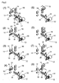
- Fig. 1 is a diagram showing how the automatic tool storing mechanism according to the present invention takes out an unused tool and a pot together from one magazine, transfers them to the waiting position, and exchanges the unused tool for the used tool attached to the main spindle.
- Fig. 2 is a diagram showing how the automatic tool storing mechanism returns, after exchange, the used tool and the pot together to another magazine.
- the pot also called tool pot
- the pot is common to all the tools (also called tool holder).
- the first magazine 10 stores the tools 12 numbered 1 to 50 and the pot 14. ( Figs. 1 and 2 show only one tool out of 50.)
- the second magazine 16 stores the tools 18 numbered 51 to 100 and the pot 14. ( Figs. 1 and 2 show only one tool out of 50.)
- Figs. 1 and 2 show only the first and second magazines.
- Fig. 1(1) shows one example of the initial state.
- the tool 12 numbered 1 which is stored in the first magazine 10, is called out by the control means (not shown).
- Fig. 1(2) the tool 12 numbered 1 (which has been called out) and the pot 14 for it are taken out together from the first magazine 10. They are transferred rightward in Fig. 1 and positioned under the pot moving arm 22.
- the pot moving arm 22 goes down and grabs the tool 12 numbered 1 (by its V-shaped flange) and the pot 14 with its claws.
- the tool exchanging arm 28 exchanges the unused tool 12 numbered 1 for the used tool 18 numbered 51, which is attached to the main spindle 30.
- Fig. 1(8) shows the state in which the tool exchange has been completed.
- the pot moving arm 22 grabs the tool 18 numbered 51 (by its V-shaped flange) and the pot 14 with its claws.
- the pot moving arm 22 goes up to its initial position while it grabs the tool 18 numbered 51 (by its V-shaped flange) and the pot 14 with its claws.
- the pot moving arm 22 moves to the position for the second magazine 16 while it is grabbing the tool 18 and the pot 14.
- the pot moving arm 22 goes down to the returning position for the tool 18 numbered 51 in the second magazine 16 while it is grabbing the tool 18 and the pot 14.
- Figs. 3 to 8 show one example of the automatic tool storing mechanism which has been illustrated in Figs. 1 and 2 .
- It has a plurality of magazines (say, five magazines numbered 10, 16, 40, 46, and 50) of the same structure, which are arranged in a line in the longitudinal direction.
- Each magazine (10, 16, 40, 46, and 50) is rotatably arranged so that the pots 14, which are common to them, make a circle endlessly.
- Each pot 14 is provided with a variety of tools 12 and 18 (only for illustration in Figs. 1 and 2 ).
- the total number of the pots 14 that can be stored in all the magazines may be several hundreds (say, 300).
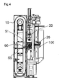
- the specific pot 14 provided with the tools 12 and 18 is selected (or called out) by the control device (not shown), and then it is transferred from the position 90 close to the magazine (shown in Fig. 4 ) to the waiting position 100 close to the main spindle by the transporting means (mentioned later).
- the guide for pot transportation is comprised of the first guide part 51 and the second guide part 26.
- the former which is close to the magazine, is positioned in front of each magazine, and the latter is positioned between the former and the waiting position 100.
- the pot moving means has first driving means and second driving means, and the pot moving arm 22.
- the first driving means 55 (which is preferably a hydraulic cylinder) moves the pot provided with tools horizontally between the first guide part 51 and each magazine.
- the second driving means 101 (which preferably includes a ball screw and a servo motor) moves the pot provided with tools horizontally along the second guide part 26.
- the pot moving arm 22 moves the pot provided with tools vertically between the first guide part 51 and the second guide part 26.
- the automatic tool storing mechanism has the two rail-like guides 61 for the pot moving arm which run parallel horizontally on both sides thereof. Along the guide 61 are arranged in a line other magazines.
- the pot moving arm 22 is moved up and down by the vertical driving part 71.
- the running driving part 77 (which preferably contains a reducer and a servo motor) through the two belts 73 and 75 extending on both side of the automatic tool storing mechanism.
- the first guide part 51 is positioned as desired in the longitudinal and lateral directions by the two guides 61 for the pot moving arm and the pot moving arm 22.
- the tool 12 numbered 1 is selected (called out) by the control device (not shown).
- the tool 12 numbered 1 and the pot 14 for it are pushed out together from the first magazine 10 by the hydraulic cylinder 55 installed at the pot entrance and exit of the magazine 10. It is transferred rightward (in Fig. 6 ) along the first guide part 51.
- the pot 14 is held by the pot holding part 59 by the action of the pot lock cylinder 57 until the tool 12 numbered 1 and the pot 14 for it reaches the position under the pot moving arm 22.
- the symbol 103 denotes the pot lock cylinder to lock and hold the tool and the pot 14 with the claws 22a, 22b, and 22c.
- the pot holding part 65 holds the pot 14 by the action of the pot lock cylinder 105. With the pot 14 held, the pot 14 and the tool 12 contained therein are transferred to the waiting position 100 by the second driving means 101.
- the tool exchanging arm 28 is activated.
- the paired holding parts 28a and 28b turn to exchange the unused tool 12 numbered 1 for the used tool 18 numbered 51 attached to the main spindle 30. In other words, it detaches the tool 12 numbered 1 from the pot 14 and removes the tool 18 numbered 51 from the main spindle 30 and then it turns them through 180° and attaches the tool 12 numbered 1 to the main spindle 30 and places the tool 18 numbered 51 in the pot 18.
- the used tool 18 numbered 51 and the pot 14 are transferred to the prescribed magazine along the guide, as shown in Fig. 2 .
- the pot lock cylinders 103 and 105, the pot moving arm 22, the holding parts 59 and 65, the hydraulic cylinder 55, and others are activated in the order which is reverse to the order in which the pot 14 is transported to the waiting position 100.
- the tool and the pot are moved together between the magazine and the waiting position 100, and the pot is supported.
Landscapes
- Engineering & Computer Science (AREA)
- Mechanical Engineering (AREA)
- Automatic Tool Replacement In Machine Tools (AREA)
- Warehouses Or Storage Devices (AREA)
Description
- The present invention relates to an automatic tool storing mechanism equipped with a magazine to store a large number of tools and pots.
- Most machine tools, especially machining centers, are equipped with an automatic tool exchanging mechanism, and they recently need a large number of tools and they are provided with more than one magazine to store the increased tools. Each magazine includes a large number of pots which are connected by chains and each pot is provided with a variety of tools.
- There is known an automatic tool exchanging device, as disclosed in Japanese Patent Laid-open Nos.
2003-291046 2008-155343 - The conventional automatic tool exchanging device is so designed as to take out a selected tool from those which are arranged in the magazine. This action is accomplished by grabbing the tool with claws by its V-shaped flange. The pot from which the tool has been taken out is left in the magazine, and only the tool is transported from the magazine to the waiting position.
- According to the conventional method, tool transportation is accomplished by separating a tool from the pot and grabbing it with claws by its V-shaped flange. The disadvantage of this method is that a heavy or long cutting tool is liable to lean during transportation, thereby causing instability in long or fast transportation.
- Moreover, the claws need high rigidity to firmly grab the tool by its V-shaped flange.
- JPS50-112874 discloses tool storing mechanism wherein tools are stored and transported in guiding blocks, according to the preamble of
claim 1. - It is an object of the present invention to provide an automatic tool storing mechanism which ensures stable tool transportation without tools leaning even in the case of heavy or long cutting tools.
- According to a mode of the present invention, an automatic tool storing mechanism comprises: at least one magazine holding a number of pots each provided with tools; transporting means to transport the pot provided with tools one by one between the position close to the magazine and the waiting position close to the main spindle; and a tool exchanging arm to take out an unused tool from the pot waiting at the waiting position and attach it to the main spindle and remove a used tool from the main spindle and place it in the pot.
- The transporting means possesses: a guide installed between the magazine-side position and the waiting position close to the main spindle; and
pot moving means to move the pot provided with tools along the guide. - The guide possesses: a first guide part close to the magazine; and a second guide part which guides the tool-mounted pot between the first guide part and the waiting position.
- The pot moving means further possesses a pot moving arm to move the tool-mounted pot between the first guide part and the second guide part.
- Also, a plurality of magazines are arranged side by side along the guide for the pot moving arm and which has a means to drive the pot moving arm on the guide for the pot moving arm, such that it stops the pot moving arm at one selected magazine and moves the tool-mounted pot between the magazine and the first guide part, and in which the total number of the pots housed in the magazines is several hundreds.
- In addition, it is preferable that the pot moving means possesses: a hydraulic cylinder to move the tool-mounted pot between the first guide part and the magazine; and a ball screw and a servo motor to move the tool-mounted pot.
- Preferably, the pot moving arm runs along the guide for the pot moving arm with the help of belts, and possesses claws to grab the pot and claws to grab the tool.
- Embodiments of the present invention will be described in detail based on the following figures, wherein:
-
Fig. 1 is a diagram illustrating how the automatic tool storing mechanism according to one example of the present invention transfers the tool and pot from the first magazine to the waiting position; -
Fig. 2 is a diagram illustrating how the automatic tool storing mechanism shown inFig. 1 transfers the tool and pot from the waiting position to the second magazine; -
Fig. 3 is a schematic perspective view of the automatic tool storing mechanism according to a preferred example of the present invention; -
Fig. 4 is a diagram illustrating the relation between one magazine and the transporting means of the automatic tool storing mechanism shown inFig. 3 ; -
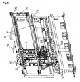
Fig. 5 is a slightly enlarged schematic perspective view of the automatic tool storing mechanism shown inFig. 3 ; -
Fig. 6 is a slightly enlarged schematic view of the automatic tool storing mechanism shown inFig. 3 ; -
Fig. 7 is a diagram showing the relation between the pot moving arm and the claws and between the tool and the pot in the automatic tool storing mechanism shown inFig. 3 ; -
Fig. 8 shows the paired claws of the pot moving arm shown inFig. 7 ; -
Fig. 9 is a schematic top view showing the three pairs of claws of the pot moving arm shown inFig. 7 ; and -
Fig. 10 is a schematic side view showing the three pairs of the pot moving arm shown inFig. 7 . - The preferred embodiments of the present invention will be described in more detail with reference to the accompanying drawings.
-
Fig. 1 is a diagram showing how the automatic tool storing mechanism according to the present invention takes out an unused tool and a pot together from one magazine, transfers them to the waiting position, and exchanges the unused tool for the used tool attached to the main spindle. -
Fig. 2 is a diagram showing how the automatic tool storing mechanism returns, after exchange, the used tool and the pot together to another magazine. - The pot (also called tool pot) is common to all the tools (also called tool holder).
- In the embodiments shown in
Figs. 1 and2 , thefirst magazine 10 stores thetools 12 numbered 1 to 50 and thepot 14. (Figs. 1 and2 show only one tool out of 50.) Thesecond magazine 16 stores thetools 18 numbered 51 to 100 and thepot 14. (Figs. 1 and2 show only one tool out of 50.)Figs. 1 and2 show only the first and second magazines. -
Fig. 1(1) shows one example of the initial state. Thetool 12 numbered 1, which is stored in thefirst magazine 10, is called out by the control means (not shown). - In
Fig. 1(2) , thetool 12 numbered 1 (which has been called out) and thepot 14 for it are taken out together from thefirst magazine 10. They are transferred rightward inFig. 1 and positioned under thepot moving arm 22. - In
Fig. 1(3) , thepot moving arm 22 goes down and grabs thetool 12 numbered 1 (by its V-shaped flange) and thepot 14 with its claws. - In
Fig. 1(4) , thepot moving arm 22 goes up so that thetool 12 numbered 1 and thepot 14 are moved to the entrance of theguide 26. - In
Fig. 1(5) , thetool 12 numbered 1 and thepot 14, which are held by the claws, remain at the entrance of theguide 26, and only thepot moving arm 22 goes up so that the initial state is restored. - In
Fig. 1(6) , thetool 12 numbered 1 and thepot 14 are moved together to the waiting position along theguide 26 while they are being held. - In
Fig. 1(7) , thetool exchanging arm 28 exchanges theunused tool 12 numbered 1 for the usedtool 18 numbered 51, which is attached to themain spindle 30. -
Fig. 1(8) shows the state in which the tool exchange has been completed. - In
Fig. 2(1) , the usedtool 18 numbered 51 (which has been exchanged) and thepot 14 for it are moved together leftward to the entrance of theguide 26. - In
Fig. 2(2) , the usedtool 18 numbered 51 and thepot 14 are positioned under thepot moving arm 22. - In
Fig. 2(3) , thepot moving arm 22 grabs thetool 18 numbered 51 (by its V-shaped flange) and thepot 14 with its claws. - In
Fig. 2(4) , thepot moving arm 22 goes up to its initial position while it grabs thetool 18 numbered 51 (by its V-shaped flange) and thepot 14 with its claws. - In
Fig. 2(5) , thepot moving arm 22 moves to the position for thesecond magazine 16 while it is grabbing thetool 18 and thepot 14. - In
Fig. 2(6) , thepot moving arm 22 goes down to the returning position for thetool 18 numbered 51 in thesecond magazine 16 while it is grabbing thetool 18 and thepot 14. - In
Fig. 2(7) , only thepot moving arm 22 goes up, away from thetool 18 and thepot 14, to the position for the initial state. - In
Fig. 2(8) , thetool 18 numbered 51 is returned, together with thepot 14, to thesecond magazine 16. As the result, the entire system restores its initial state. -
Figs. 3 to 8 show one example of the automatic tool storing mechanism which has been illustrated inFigs. 1 and2 . - It has a plurality of magazines (say, five magazines numbered 10, 16, 40, 46, and 50) of the same structure, which are arranged in a line in the longitudinal direction.
- Each magazine (10, 16, 40, 46, and 50) is rotatably arranged so that the
pots 14, which are common to them, make a circle endlessly. Eachpot 14 is provided with a variety oftools 12 and 18 (only for illustration inFigs. 1 and2 ). - The total number of the
pots 14 that can be stored in all the magazines may be several hundreds (say, 300). - The
specific pot 14 provided with thetools position 90 close to the magazine (shown inFig. 4 ) to the waitingposition 100 close to the main spindle by the transporting means (mentioned later). - The guide for pot transportation is comprised of the
first guide part 51 and thesecond guide part 26. The former, which is close to the magazine, is positioned in front of each magazine, and the latter is positioned between the former and the waitingposition 100. - The pot moving means has first driving means and second driving means, and the
pot moving arm 22. The first driving means 55 (which is preferably a hydraulic cylinder) moves the pot provided with tools horizontally between thefirst guide part 51 and each magazine. The second driving means 101 (which preferably includes a ball screw and a servo motor) moves the pot provided with tools horizontally along thesecond guide part 26. Thepot moving arm 22 moves the pot provided with tools vertically between thefirst guide part 51 and thesecond guide part 26. - As shown in
Fig. 5 , the automatic tool storing mechanism has the two rail-like guides 61 for the pot moving arm which run parallel horizontally on both sides thereof. Along theguide 61 are arranged in a line other magazines. - The
pot moving arm 22 is moved up and down by the vertical drivingpart 71. - It is moved horizontally to the position of the selected magazine along the two
guides 61 for the pot moving arm by the running driving part 77 (which preferably contains a reducer and a servo motor) through the twobelts - The
first guide part 51 is positioned as desired in the longitudinal and lateral directions by the twoguides 61 for the pot moving arm and thepot moving arm 22. - This is explained with reference to
Fig. 6 . - Of the many tools stored in the
first magazine 10, thetool 12 numbered 1 is selected (called out) by the control device (not shown). Thetool 12 numbered 1 and thepot 14 for it are pushed out together from thefirst magazine 10 by thehydraulic cylinder 55 installed at the pot entrance and exit of themagazine 10. It is transferred rightward (inFig. 6 ) along thefirst guide part 51. At this time, thepot 14 is held by thepot holding part 59 by the action of thepot lock cylinder 57 until thetool 12 numbered 1 and thepot 14 for it reaches the position under thepot moving arm 22. - Then, the
pot moving arm 22 is lowered. The V-shaped flange part of thetool 12 numbered 1 is grabbed by theclaw 22a and two parts of thepot 14 are grabbed by theclaws - The
symbol 103 denotes the pot lock cylinder to lock and hold the tool and thepot 14 with theclaws - With the
pot lock cylinder 103 activated (in its lock state), thepot moving arm 22 is raised and thetool 12 numbered 1 and thepot 14 are moved together to the entrance of thesecond guide part 26. - At the entrance of the
second guide part 26, thepot holding part 65 holds thepot 14 by the action of thepot lock cylinder 105. With thepot 14 held, thepot 14 and thetool 12 contained therein are transferred to the waitingposition 100 by the second driving means 101. - After the
unused tool 12 numbered 1 and thepot 14 have reached the waitingposition 100, thetool exchanging arm 28 is activated. The paired holdingparts unused tool 12 numbered 1 for the usedtool 18 numbered 51 attached to themain spindle 30. In other words, it detaches thetool 12 numbered 1 from thepot 14 and removes thetool 18 numbered 51 from themain spindle 30 and then it turns them through 180° and attaches thetool 12 numbered 1 to themain spindle 30 and places thetool 18 numbered 51 in thepot 18. - The used
tool 18 numbered 51 and thepot 14 are transferred to the prescribed magazine along the guide, as shown inFig. 2 . At this time, thepot lock cylinders pot moving arm 22, the holdingparts hydraulic cylinder 55, and others are activated in the order which is reverse to the order in which thepot 14 is transported to the waitingposition 100. - According to the above-mentioned embodiments, the tool and the pot are moved together between the magazine and the waiting
position 100, and the pot is supported.
Claims (5)
- An automatic tool storing mechanism comprising:- at least one magazine (10, 16, 40, 46, 50) holding a number of pots (14) each provided with a tool (12, 18);- transporting means for transporting one of the pots (14) provided with a tool (12, 18), one by one, between a magazine-side position (90) close to the magazine (10, 16, 40, 46, 50) and a waiting position (100) close to a main spindle (30); and- a tool exchanging arm (28) to take out an unused tool (12, 18) from the one pot (14), when it is waiting at the waiting position (100), and attach the unused tool (12, 18) to the main spindle (30) and remove a used tool (12, 18) from the main spindle (30) and place it in the pot (14);
wherein the transporting means possesses:- a pot guide (51, 26) installed between the magazine-side position (90) close to the magazine (10, 16, 40, 46, 50) and the waiting position (100) close to the main spindle (30); and- pot moving means for moving the pots (14) provided with a tool (12, 18) one by one along the guide;
wherein the pot guide (51, 26) possesses:- a first guide part (51) positioned close to the magazine (10, 16, 40, 46, 50); and- a second guide part (26) which guides the pot (14) provided with the tool (12, 18) between the first guide part (51) and the waiting position (100);
wherein the pot moving means possesses:- a pot moving arm (22) to move the pot (14) provided with a tool (12, 18) between the first guide part (51) and the second guide part (26),
characterized in that a plurality of magazines (10, 16, 40, 46, 50) are arranged side by side along a guide for the pot moving arm (22) and in that it has a means to drive the pot moving arm (22) on the guide for the pot moving arm (22), such that it stops the pot moving arm (22) at one selected magazine and moves the pot (14) provided with a tool (12, 18) between the magazine (10, 16, 40, 46, 50) and the first guide part (51). - The automatic tool storing mechanism according to Claim 1, wherein the pot moving means possesses:- a hydraulic cylinder (55) to move the pot (14) provided with a tool (12, 18) between the first guide part (51) and the magazine(10, 16, 40, 46, 50) ; and- a ball screw and a servo motor (101) to move the pot (14) provided with a tool (12,18).
- The automatic tool storing mechanism according to Claim 1 or 2, in which the total number of the pots (14) housed in the magazines (10, 16, 40, 46, 50) is several hundreds.
- The automatic tool storing mechanism according to Claim 1 or 3, wherein the pot moving arm (22) runs along the guide for the pot moving arm (22) with the help of belts (73, 75).
- The automatic tool storing mechanism according to any of Claims 1 to 4, wherein the pot moving arm (22) possesses claws (22b, 22c) to grab the pot (14) and claws (22a) to grab the tool (12,18).
Applications Claiming Priority (2)
| Application Number | Priority Date | Filing Date | Title |
|---|---|---|---|
| JP2009104249A JP4972120B2 (en) | 2009-04-22 | 2009-04-22 | Automatic tool storage mechanism |
| PCT/JP2010/057321 WO2010123135A1 (en) | 2009-04-22 | 2010-04-20 | Automatic tool storage mechanism |
Publications (3)
| Publication Number | Publication Date |
|---|---|
| EP2422924A1 EP2422924A1 (en) | 2012-02-29 |
| EP2422924A4 EP2422924A4 (en) | 2013-05-29 |
| EP2422924B1 true EP2422924B1 (en) | 2014-07-23 |
Family
ID=43011246
Family Applications (1)
| Application Number | Title | Priority Date | Filing Date |
|---|---|---|---|
| EP10767187.7A Active EP2422924B1 (en) | 2009-04-22 | 2010-04-20 | Automatic tool storage mechanism |
Country Status (7)
| Country | Link |
|---|---|
| US (1) | US8360945B2 (en) |
| EP (1) | EP2422924B1 (en) |
| JP (1) | JP4972120B2 (en) |
| KR (1) | KR101232007B1 (en) |
| CN (1) | CN102099152B (en) |
| TW (1) | TWI392559B (en) |
| WO (1) | WO2010123135A1 (en) |
Families Citing this family (9)
| Publication number | Priority date | Publication date | Assignee | Title |
|---|---|---|---|---|
| KR101788865B1 (en) * | 2010-12-13 | 2017-10-20 | 두산공작기계 주식회사 | the tool carrier unit of the tool magazine |
| DE102011006811A1 (en) * | 2011-04-05 | 2012-10-11 | Deckel Maho Pfronten Gmbh | Tool handling device for machine tools |
| TW201302376A (en) * | 2011-07-13 | 2013-01-16 | Jian Xue Qin | Automatic tool changing mechanism of CNC machining center |
| KR101383442B1 (en) * | 2012-06-14 | 2014-04-08 | 주식회사 성산암데코 | High speed and automatic tool changer for manufacturing calliper housing of break system |
| JP5667254B1 (en) * | 2013-08-02 | 2015-02-12 | キタムラ機械株式会社 | Automatic tool storage mechanism |
| CN104191290B (en) * | 2014-08-25 | 2016-03-30 | 无锡众望四维科技有限公司 | Lock core Special clamping device |
| JP6525737B2 (en) | 2015-05-29 | 2019-06-05 | 東芝機械株式会社 | Machine Tools |
| JP6342940B2 (en) | 2016-04-19 | 2018-06-13 | キタムラ機械株式会社 | Automatic tool change system for machine tools |
| JP6998158B2 (en) * | 2017-09-07 | 2022-01-18 | 株式会社ディスコ | Cutting blade feeder |
Family Cites Families (25)
| Publication number | Priority date | Publication date | Assignee | Title |
|---|---|---|---|---|
| JPS50112874A (en) * | 1974-02-18 | 1975-09-04 | ||
| JPS5726897B2 (en) * | 1974-04-30 | 1982-06-07 | ||
| IT1037252B (en) * | 1975-04-14 | 1979-11-10 | Mandelli Spa | MACHINE TOOL CONTAINING A SINGLE SPINDLE SUITABLE TO AUTOMATICALLY ASSUME THE HORIZONTAL POSITION THE VERTICAL POSITION AND A SINGLE DEVICE FOR AUTOMATIC CHANGE OF TOOLS |
| AR225485A1 (en) * | 1980-02-08 | 1982-03-31 | Oerlikon Buehrle Ag | A MACHINE-TOOL |
| JPS56157935A (en) * | 1980-05-09 | 1981-12-05 | Kurashiki Kikai Kk | Tool magazine at machining center |
| JPS61142038A (en) * | 1984-12-12 | 1986-06-28 | Toshiba Mach Co Ltd | Attachment-tool replacing apparatus |
| JPS62199333A (en) * | 1986-02-26 | 1987-09-03 | Okuma Mach Works Ltd | Tool replacing method in machine tool |
| JPH01240244A (en) * | 1988-03-18 | 1989-09-25 | Nkk Corp | Tool changing method and device for NC machine tool |
| JPH0438335A (en) | 1990-06-05 | 1992-02-07 | Mitsubishi Electric Corp | Outdoor water piping antifreezing device |
| JPH0438335U (en) * | 1990-07-31 | 1992-03-31 | ||
| JP3642069B2 (en) * | 1994-03-09 | 2005-04-27 | 豊田工機株式会社 | Automatic tool changer |
| JP3246647B2 (en) * | 1996-03-12 | 2002-01-15 | キタムラ機械株式会社 | Tool magazine for automatic tool change |
| JP3177766B2 (en) * | 1996-04-18 | 2001-06-18 | オークマ株式会社 | Tool transfer device |
| GB2331946B (en) * | 1997-12-02 | 1999-10-20 | Nippei Toyama Corp | Tool change method and tool change device |
| JP4401482B2 (en) * | 1999-07-27 | 2010-01-20 | 東芝機械株式会社 | Matrix-type tool magazine |
| JP2002355728A (en) * | 2001-05-30 | 2002-12-10 | Howa Mach Ltd | Tool magazine equipment for machine tools |
| JP2002355729A (en) * | 2001-05-30 | 2002-12-10 | Hitachi Seiki Co Ltd | Automatic tool changer for machine tools |
| JP2003291046A (en) | 2002-03-29 | 2003-10-14 | Toyoda Mach Works Ltd | Automatic tool changer |
| JP2004276161A (en) * | 2003-03-14 | 2004-10-07 | Kitamura Mach Co Ltd | Tool holder replacement mechanism |
| JP4330413B2 (en) * | 2003-09-26 | 2009-09-16 | 株式会社牧野フライス製作所 | Automatic tool changer |
| AT504172B1 (en) * | 2006-09-14 | 2009-08-15 | Miguel Muser | DEVICE FOR LOADING AND UNLOADING A MACHINE TOOL |
| JP2008149416A (en) * | 2006-12-19 | 2008-07-03 | Nisshinbo Ind Inc | Machining center |
| JP2008155343A (en) * | 2006-12-26 | 2008-07-10 | Kitamura Mach Co Ltd | Tool changing method and machining center |
| JP5082591B2 (en) * | 2007-05-31 | 2012-11-28 | ブラザー工業株式会社 | Tool changer |
| US7635327B1 (en) * | 2009-04-02 | 2009-12-22 | Quaser Machine Tools, Inc. | Multi-layered tool magazine of CNC machine |
-
2009
- 2009-04-22 JP JP2009104249A patent/JP4972120B2/en active Active
- 2009-11-19 TW TW098139367A patent/TWI392559B/en not_active IP Right Cessation
-
2010
- 2010-04-20 US US13/055,050 patent/US8360945B2/en active Active
- 2010-04-20 CN CN2010800021313A patent/CN102099152B/en not_active Expired - Fee Related
- 2010-04-20 EP EP10767187.7A patent/EP2422924B1/en active Active
- 2010-04-20 WO PCT/JP2010/057321 patent/WO2010123135A1/en not_active Ceased
- 2010-04-20 KR KR1020117003676A patent/KR101232007B1/en active Active
Also Published As
| Publication number | Publication date |
|---|---|
| US8360945B2 (en) | 2013-01-29 |
| KR101232007B1 (en) | 2013-02-08 |
| JP2010253588A (en) | 2010-11-11 |
| TWI392559B (en) | 2013-04-11 |
| KR20120014549A (en) | 2012-02-17 |
| EP2422924A4 (en) | 2013-05-29 |
| TW201038356A (en) | 2010-11-01 |
| WO2010123135A1 (en) | 2010-10-28 |
| CN102099152B (en) | 2013-11-06 |
| EP2422924A1 (en) | 2012-02-29 |
| US20120028771A1 (en) | 2012-02-02 |
| CN102099152A (en) | 2011-06-15 |
| JP4972120B2 (en) | 2012-07-11 |
Similar Documents
| Publication | Publication Date | Title |
|---|---|---|
| US8360945B2 (en) | Automatic tool storing mechanism | |
| EP2832492B1 (en) | Automatic tool storing mechanism | |
| US20100204028A1 (en) | System for Changing and Inserting or Placing Tools on a Machine Tool and Tool Magazine for Storing Tools | |
| CN103303675A (en) | Automatic core box uncoding disk system and core box uncoding disk method | |
| JPH02147131A (en) | Punching machine with replaceable punching tool and workpiece feeder | |
| KR102004471B1 (en) | Multi type tool changer and multi-spindle type machining center with the same | |
| JP2010253588A5 (en) | ||
| US5354153A (en) | Machine tool part loading and unloading method and device particularly for machining printed circuit boards | |
| KR102057727B1 (en) | Machining center with multi-spindle | |
| CN110625423A (en) | Two side cylinders release tool magazine | |
| JP2023547546A5 (en) | ||
| KR20130030928A (en) | Device for transporting a tool in the tool magazine of a machine tool | |
| EP0038158A2 (en) | Machine tool including a tool transfer mechanism | |
| CN111591658B (en) | A knife storage and matching system | |
| US20250345891A1 (en) | Machine tool and method of operating the machine tool | |
| US4528742A (en) | Tool-change device for a machine tool | |
| WO2021048730A1 (en) | Automated system for composing or disassembling a cutting formation | |
| EP4480633A1 (en) | Manipulating device for extracting workpieces from cnc lathe and placing them on pallets | |
| JPS6161936B2 (en) | ||
| JP5283683B2 (en) | Machine Tools | |
| CN223643304U (en) | Overturning buckle cover mechanism, cutter box switching device and new cutter warehousing system | |
| CN224129228U (en) | A matrix tool magazine for use in horizontal machining centers | |
| KR100600895B1 (en) | Automatic tool transmission for dual type tool magazines | |
| JP5198545B2 (en) | Exchange device | |
| CN120363008A (en) | Matrix type tool magazine applied to horizontal machining center |
Legal Events
| Date | Code | Title | Description |
|---|---|---|---|
| PUAI | Public reference made under article 153(3) epc to a published international application that has entered the european phase |
Free format text: ORIGINAL CODE: 0009012 |
|
| 17P | Request for examination filed |
Effective date: 20101123 |
|
| AK | Designated contracting states |
Kind code of ref document: A1 Designated state(s): AT BE BG CH CY CZ DE DK EE ES FI FR GB GR HR HU IE IS IT LI LT LU LV MC MK MT NL NO PL PT RO SE SI SK SM TR |
|
| DAX | Request for extension of the european patent (deleted) | ||
| A4 | Supplementary search report drawn up and despatched |
Effective date: 20130429 |
|
| RIC1 | Information provided on ipc code assigned before grant |
Ipc: B23Q 3/157 20060101AFI20130423BHEP |
|
| 17Q | First examination report despatched |
Effective date: 20131212 |
|
| GRAP | Despatch of communication of intention to grant a patent |
Free format text: ORIGINAL CODE: EPIDOSNIGR1 |
|
| INTG | Intention to grant announced |
Effective date: 20140425 |
|
| GRAS | Grant fee paid |
Free format text: ORIGINAL CODE: EPIDOSNIGR3 |
|
| GRAA | (expected) grant |
Free format text: ORIGINAL CODE: 0009210 |
|
| AK | Designated contracting states |
Kind code of ref document: B1 Designated state(s): AT BE BG CH CY CZ DE DK EE ES FI FR GB GR HR HU IE IS IT LI LT LU LV MC MK MT NL NO PL PT RO SE SI SK SM TR |
|
| REG | Reference to a national code |
Ref country code: GB Ref legal event code: FG4D |
|
| REG | Reference to a national code |
Ref country code: CH Ref legal event code: EP |
|
| REG | Reference to a national code |
Ref country code: IE Ref legal event code: FG4D |
|
| REG | Reference to a national code |
Ref country code: AT Ref legal event code: REF Ref document number: 678580 Country of ref document: AT Kind code of ref document: T Effective date: 20140815 |
|
| REG | Reference to a national code |
Ref country code: CH Ref legal event code: NV Representative=s name: DR. LUSUARDI AG, CH |
|
| REG | Reference to a national code |
Ref country code: DE Ref legal event code: R096 Ref document number: 602010017752 Country of ref document: DE Effective date: 20140904 |
|
| REG | Reference to a national code |
Ref country code: NL Ref legal event code: T3 |
|
| REG | Reference to a national code |
Ref country code: AT Ref legal event code: MK05 Ref document number: 678580 Country of ref document: AT Kind code of ref document: T Effective date: 20140723 |
|
| REG | Reference to a national code |
Ref country code: LT Ref legal event code: MG4D |
|
| PG25 | Lapsed in a contracting state [announced via postgrant information from national office to epo] |
Ref country code: BG Free format text: LAPSE BECAUSE OF FAILURE TO SUBMIT A TRANSLATION OF THE DESCRIPTION OR TO PAY THE FEE WITHIN THE PRESCRIBED TIME-LIMIT Effective date: 20141023 Ref country code: LT Free format text: LAPSE BECAUSE OF FAILURE TO SUBMIT A TRANSLATION OF THE DESCRIPTION OR TO PAY THE FEE WITHIN THE PRESCRIBED TIME-LIMIT Effective date: 20140723 Ref country code: SE Free format text: LAPSE BECAUSE OF FAILURE TO SUBMIT A TRANSLATION OF THE DESCRIPTION OR TO PAY THE FEE WITHIN THE PRESCRIBED TIME-LIMIT Effective date: 20140723 Ref country code: ES Free format text: LAPSE BECAUSE OF FAILURE TO SUBMIT A TRANSLATION OF THE DESCRIPTION OR TO PAY THE FEE WITHIN THE PRESCRIBED TIME-LIMIT Effective date: 20140723 Ref country code: FI Free format text: LAPSE BECAUSE OF FAILURE TO SUBMIT A TRANSLATION OF THE DESCRIPTION OR TO PAY THE FEE WITHIN THE PRESCRIBED TIME-LIMIT Effective date: 20140723 Ref country code: GR Free format text: LAPSE BECAUSE OF FAILURE TO SUBMIT A TRANSLATION OF THE DESCRIPTION OR TO PAY THE FEE WITHIN THE PRESCRIBED TIME-LIMIT Effective date: 20141024 Ref country code: NO Free format text: LAPSE BECAUSE OF FAILURE TO SUBMIT A TRANSLATION OF THE DESCRIPTION OR TO PAY THE FEE WITHIN THE PRESCRIBED TIME-LIMIT Effective date: 20141023 Ref country code: PT Free format text: LAPSE BECAUSE OF FAILURE TO SUBMIT A TRANSLATION OF THE DESCRIPTION OR TO PAY THE FEE WITHIN THE PRESCRIBED TIME-LIMIT Effective date: 20141124 |
|
| PG25 | Lapsed in a contracting state [announced via postgrant information from national office to epo] |
Ref country code: AT Free format text: LAPSE BECAUSE OF FAILURE TO SUBMIT A TRANSLATION OF THE DESCRIPTION OR TO PAY THE FEE WITHIN THE PRESCRIBED TIME-LIMIT Effective date: 20140723 Ref country code: IS Free format text: LAPSE BECAUSE OF FAILURE TO SUBMIT A TRANSLATION OF THE DESCRIPTION OR TO PAY THE FEE WITHIN THE PRESCRIBED TIME-LIMIT Effective date: 20141123 Ref country code: LV Free format text: LAPSE BECAUSE OF FAILURE TO SUBMIT A TRANSLATION OF THE DESCRIPTION OR TO PAY THE FEE WITHIN THE PRESCRIBED TIME-LIMIT Effective date: 20140723 Ref country code: HR Free format text: LAPSE BECAUSE OF FAILURE TO SUBMIT A TRANSLATION OF THE DESCRIPTION OR TO PAY THE FEE WITHIN THE PRESCRIBED TIME-LIMIT Effective date: 20140723 Ref country code: CY Free format text: LAPSE BECAUSE OF FAILURE TO SUBMIT A TRANSLATION OF THE DESCRIPTION OR TO PAY THE FEE WITHIN THE PRESCRIBED TIME-LIMIT Effective date: 20140723 Ref country code: PL Free format text: LAPSE BECAUSE OF FAILURE TO SUBMIT A TRANSLATION OF THE DESCRIPTION OR TO PAY THE FEE WITHIN THE PRESCRIBED TIME-LIMIT Effective date: 20140723 |
|
| REG | Reference to a national code |
Ref country code: DE Ref legal event code: R097 Ref document number: 602010017752 Country of ref document: DE |
|
| PG25 | Lapsed in a contracting state [announced via postgrant information from national office to epo] |
Ref country code: RO Free format text: LAPSE BECAUSE OF FAILURE TO SUBMIT A TRANSLATION OF THE DESCRIPTION OR TO PAY THE FEE WITHIN THE PRESCRIBED TIME-LIMIT Effective date: 20140723 Ref country code: DK Free format text: LAPSE BECAUSE OF FAILURE TO SUBMIT A TRANSLATION OF THE DESCRIPTION OR TO PAY THE FEE WITHIN THE PRESCRIBED TIME-LIMIT Effective date: 20140723 Ref country code: SK Free format text: LAPSE BECAUSE OF FAILURE TO SUBMIT A TRANSLATION OF THE DESCRIPTION OR TO PAY THE FEE WITHIN THE PRESCRIBED TIME-LIMIT Effective date: 20140723 Ref country code: EE Free format text: LAPSE BECAUSE OF FAILURE TO SUBMIT A TRANSLATION OF THE DESCRIPTION OR TO PAY THE FEE WITHIN THE PRESCRIBED TIME-LIMIT Effective date: 20140723 Ref country code: CZ Free format text: LAPSE BECAUSE OF FAILURE TO SUBMIT A TRANSLATION OF THE DESCRIPTION OR TO PAY THE FEE WITHIN THE PRESCRIBED TIME-LIMIT Effective date: 20140723 |
|
| PLBE | No opposition filed within time limit |
Free format text: ORIGINAL CODE: 0009261 |
|
| STAA | Information on the status of an ep patent application or granted ep patent |
Free format text: STATUS: NO OPPOSITION FILED WITHIN TIME LIMIT |
|
| 26N | No opposition filed |
Effective date: 20150424 |
|
| PG25 | Lapsed in a contracting state [announced via postgrant information from national office to epo] |
Ref country code: LU Free format text: LAPSE BECAUSE OF FAILURE TO SUBMIT A TRANSLATION OF THE DESCRIPTION OR TO PAY THE FEE WITHIN THE PRESCRIBED TIME-LIMIT Effective date: 20150420 Ref country code: MC Free format text: LAPSE BECAUSE OF FAILURE TO SUBMIT A TRANSLATION OF THE DESCRIPTION OR TO PAY THE FEE WITHIN THE PRESCRIBED TIME-LIMIT Effective date: 20140723 Ref country code: SI Free format text: LAPSE BECAUSE OF FAILURE TO SUBMIT A TRANSLATION OF THE DESCRIPTION OR TO PAY THE FEE WITHIN THE PRESCRIBED TIME-LIMIT Effective date: 20140723 |
|
| REG | Reference to a national code |
Ref country code: CH Ref legal event code: PL |
|
| REG | Reference to a national code |
Ref country code: NL Ref legal event code: MM Effective date: 20150501 |
|
| REG | Reference to a national code |
Ref country code: IE Ref legal event code: MM4A |
|
| PG25 | Lapsed in a contracting state [announced via postgrant information from national office to epo] |
Ref country code: LI Free format text: LAPSE BECAUSE OF NON-PAYMENT OF DUE FEES Effective date: 20150430 Ref country code: CH Free format text: LAPSE BECAUSE OF NON-PAYMENT OF DUE FEES Effective date: 20150430 |
|
| PG25 | Lapsed in a contracting state [announced via postgrant information from national office to epo] |
Ref country code: NL Free format text: LAPSE BECAUSE OF NON-PAYMENT OF DUE FEES Effective date: 20150501 |
|
| REG | Reference to a national code |
Ref country code: FR Ref legal event code: PLFP Year of fee payment: 7 |
|
| PG25 | Lapsed in a contracting state [announced via postgrant information from national office to epo] |
Ref country code: IE Free format text: LAPSE BECAUSE OF NON-PAYMENT OF DUE FEES Effective date: 20150420 |
|
| PG25 | Lapsed in a contracting state [announced via postgrant information from national office to epo] |
Ref country code: BE Free format text: LAPSE BECAUSE OF FAILURE TO SUBMIT A TRANSLATION OF THE DESCRIPTION OR TO PAY THE FEE WITHIN THE PRESCRIBED TIME-LIMIT Effective date: 20140723 |
|
| PG25 | Lapsed in a contracting state [announced via postgrant information from national office to epo] |
Ref country code: MT Free format text: LAPSE BECAUSE OF FAILURE TO SUBMIT A TRANSLATION OF THE DESCRIPTION OR TO PAY THE FEE WITHIN THE PRESCRIBED TIME-LIMIT Effective date: 20140723 |
|
| REG | Reference to a national code |
Ref country code: FR Ref legal event code: PLFP Year of fee payment: 8 |
|
| PG25 | Lapsed in a contracting state [announced via postgrant information from national office to epo] |
Ref country code: SM Free format text: LAPSE BECAUSE OF FAILURE TO SUBMIT A TRANSLATION OF THE DESCRIPTION OR TO PAY THE FEE WITHIN THE PRESCRIBED TIME-LIMIT Effective date: 20140723 Ref country code: HU Free format text: LAPSE BECAUSE OF FAILURE TO SUBMIT A TRANSLATION OF THE DESCRIPTION OR TO PAY THE FEE WITHIN THE PRESCRIBED TIME-LIMIT; INVALID AB INITIO Effective date: 20100420 |
|
| PG25 | Lapsed in a contracting state [announced via postgrant information from national office to epo] |
Ref country code: TR Free format text: LAPSE BECAUSE OF FAILURE TO SUBMIT A TRANSLATION OF THE DESCRIPTION OR TO PAY THE FEE WITHIN THE PRESCRIBED TIME-LIMIT Effective date: 20140723 |
|
| REG | Reference to a national code |
Ref country code: FR Ref legal event code: PLFP Year of fee payment: 9 |
|
| PG25 | Lapsed in a contracting state [announced via postgrant information from national office to epo] |
Ref country code: MK Free format text: LAPSE BECAUSE OF FAILURE TO SUBMIT A TRANSLATION OF THE DESCRIPTION OR TO PAY THE FEE WITHIN THE PRESCRIBED TIME-LIMIT Effective date: 20140723 |
|
| P01 | Opt-out of the competence of the unified patent court (upc) registered |
Effective date: 20230517 |
|
| PGFP | Annual fee paid to national office [announced via postgrant information from national office to epo] |
Ref country code: GB Payment date: 20260327 Year of fee payment: 17 |
|
| PGFP | Annual fee paid to national office [announced via postgrant information from national office to epo] |
Ref country code: IT Payment date: 20260430 Year of fee payment: 17 |
|
| PGFP | Annual fee paid to national office [announced via postgrant information from national office to epo] |
Ref country code: DE Payment date: 20260422 Year of fee payment: 17 |
|
| PGFP | Annual fee paid to national office [announced via postgrant information from national office to epo] |
Ref country code: FR Payment date: 20260422 Year of fee payment: 17 |