EP2422909A1 - Structure for preventing falling off of riving knife fastener for rotary saw - Google Patents
Structure for preventing falling off of riving knife fastener for rotary saw Download PDFInfo
- Publication number
- EP2422909A1 EP2422909A1 EP10766937A EP10766937A EP2422909A1 EP 2422909 A1 EP2422909 A1 EP 2422909A1 EP 10766937 A EP10766937 A EP 10766937A EP 10766937 A EP10766937 A EP 10766937A EP 2422909 A1 EP2422909 A1 EP 2422909A1
- Authority
- EP
- European Patent Office
- Prior art keywords
- splitter
- removal
- fixing
- loosened
- threaded shaft
- Prior art date
- Legal status (The legal status is an assumption and is not a legal conclusion. Google has not performed a legal analysis and makes no representation as to the accuracy of the status listed.)
- Withdrawn
Links
- 238000005520 cutting process Methods 0.000 claims description 25
- 230000002265 prevention Effects 0.000 claims description 17
- 230000006866 deterioration Effects 0.000 abstract description 2
- 230000000669 biting effect Effects 0.000 description 4
- 238000010276 construction Methods 0.000 description 4
- 230000006872 improvement Effects 0.000 description 3
- 238000003780 insertion Methods 0.000 description 2
- 230000037431 insertion Effects 0.000 description 2
- 230000002093 peripheral effect Effects 0.000 description 2
- 239000004677 Nylon Substances 0.000 description 1
- 230000008859 change Effects 0.000 description 1
- 238000007796 conventional method Methods 0.000 description 1
- 230000004048 modification Effects 0.000 description 1
- 238000012986 modification Methods 0.000 description 1
- 229920001778 nylon Polymers 0.000 description 1
Images


Classifications
-
- B—PERFORMING OPERATIONS; TRANSPORTING
- B27—WORKING OR PRESERVING WOOD OR SIMILAR MATERIAL; NAILING OR STAPLING MACHINES IN GENERAL
- B27B—SAWS FOR WOOD OR SIMILAR MATERIAL; COMPONENTS OR ACCESSORIES THEREFOR
- B27B5/00—Sawing machines working with circular or cylindrical saw blades; Components or equipment therefor
- B27B5/16—Saw benches
- B27B5/22—Saw benches with non-feedable circular saw blade
- B27B5/222—Saw benches with non-feedable circular saw blade the saw blade being arranged underneath the work-table; Guiding arrangements for the work-table
-
- B—PERFORMING OPERATIONS; TRANSPORTING
- B27—WORKING OR PRESERVING WOOD OR SIMILAR MATERIAL; NAILING OR STAPLING MACHINES IN GENERAL
- B27G—ACCESSORY MACHINES OR APPARATUS FOR WORKING WOOD OR SIMILAR MATERIALS; TOOLS FOR WORKING WOOD OR SIMILAR MATERIALS; SAFETY DEVICES FOR WOOD WORKING MACHINES OR TOOLS
- B27G19/00—Safety guards or devices specially adapted for wood saws; Auxiliary devices facilitating proper operation of wood saws
- B27G19/08—Accessories for keeping open the saw kerf, e.g. riving knives or wedge plates
-
- F—MECHANICAL ENGINEERING; LIGHTING; HEATING; WEAPONS; BLASTING
- F16—ENGINEERING ELEMENTS AND UNITS; GENERAL MEASURES FOR PRODUCING AND MAINTAINING EFFECTIVE FUNCTIONING OF MACHINES OR INSTALLATIONS; THERMAL INSULATION IN GENERAL
- F16B—DEVICES FOR FASTENING OR SECURING CONSTRUCTIONAL ELEMENTS OR MACHINE PARTS TOGETHER, e.g. NAILS, BOLTS, CIRCLIPS, CLAMPS, CLIPS OR WEDGES; JOINTS OR JOINTING
- F16B41/00—Measures against loss of bolts, nuts, or pins; Measures against unauthorised operation of bolts, nuts or pins
-
- F—MECHANICAL ENGINEERING; LIGHTING; HEATING; WEAPONS; BLASTING
- F16—ENGINEERING ELEMENTS AND UNITS; GENERAL MEASURES FOR PRODUCING AND MAINTAINING EFFECTIVE FUNCTIONING OF MACHINES OR INSTALLATIONS; THERMAL INSULATION IN GENERAL
- F16B—DEVICES FOR FASTENING OR SECURING CONSTRUCTIONAL ELEMENTS OR MACHINE PARTS TOGETHER, e.g. NAILS, BOLTS, CIRCLIPS, CLAMPS, CLIPS OR WEDGES; JOINTS OR JOINTING
- F16B5/00—Joining sheets or plates, e.g. panels, to one another or to strips or bars parallel to them
- F16B5/02—Joining sheets or plates, e.g. panels, to one another or to strips or bars parallel to them by means of fastening members using screw-thread
- F16B5/0216—Joining sheets or plates, e.g. panels, to one another or to strips or bars parallel to them by means of fastening members using screw-thread the position of the plates to be connected being adjustable
- F16B5/0225—Joining sheets or plates, e.g. panels, to one another or to strips or bars parallel to them by means of fastening members using screw-thread the position of the plates to be connected being adjustable allowing for adjustment parallel to the plane of the plates
-
- F—MECHANICAL ENGINEERING; LIGHTING; HEATING; WEAPONS; BLASTING
- F16—ENGINEERING ELEMENTS AND UNITS; GENERAL MEASURES FOR PRODUCING AND MAINTAINING EFFECTIVE FUNCTIONING OF MACHINES OR INSTALLATIONS; THERMAL INSULATION IN GENERAL
- F16B—DEVICES FOR FASTENING OR SECURING CONSTRUCTIONAL ELEMENTS OR MACHINE PARTS TOGETHER, e.g. NAILS, BOLTS, CIRCLIPS, CLAMPS, CLIPS OR WEDGES; JOINTS OR JOINTING
- F16B35/00—Screw-bolts; Stay-bolts; Screw-threaded studs; Screws; Set screws
- F16B35/04—Screw-bolts; Stay-bolts; Screw-threaded studs; Screws; Set screws with specially-shaped head or shaft in order to fix the bolt on or in an object
- F16B35/041—Specially-shaped shafts
-
- F—MECHANICAL ENGINEERING; LIGHTING; HEATING; WEAPONS; BLASTING
- F16—ENGINEERING ELEMENTS AND UNITS; GENERAL MEASURES FOR PRODUCING AND MAINTAINING EFFECTIVE FUNCTIONING OF MACHINES OR INSTALLATIONS; THERMAL INSULATION IN GENERAL
- F16B—DEVICES FOR FASTENING OR SECURING CONSTRUCTIONAL ELEMENTS OR MACHINE PARTS TOGETHER, e.g. NAILS, BOLTS, CIRCLIPS, CLAMPS, CLIPS OR WEDGES; JOINTS OR JOINTING
- F16B39/00—Locking of screws, bolts or nuts
- F16B39/22—Locking of screws, bolts or nuts in which the locking takes place during screwing down or tightening
- F16B39/28—Locking of screws, bolts or nuts in which the locking takes place during screwing down or tightening by special members on, or shape of, the nut or bolt
- F16B39/34—Locking by deformable inserts or like parts
-
- Y—GENERAL TAGGING OF NEW TECHNOLOGICAL DEVELOPMENTS; GENERAL TAGGING OF CROSS-SECTIONAL TECHNOLOGIES SPANNING OVER SEVERAL SECTIONS OF THE IPC; TECHNICAL SUBJECTS COVERED BY FORMER USPC CROSS-REFERENCE ART COLLECTIONS [XRACs] AND DIGESTS
- Y10—TECHNICAL SUBJECTS COVERED BY FORMER USPC
- Y10T—TECHNICAL SUBJECTS COVERED BY FORMER US CLASSIFICATION
- Y10T83/00—Cutting
- Y10T83/202—With product handling means
- Y10T83/2074—Including means to divert one portion of product from another
- Y10T83/2077—By kerf entering guide
Definitions
- This invention relates to a structure for preventing a fixing tool, which is used for fixing a splitter for preventing so-called kickback to a splitter mounting base, from being removed from the mounting base when loosened, for example, in a cutting machine called a table saw
- a stationary cutting machine generally referred to as a table saw has a table on which a workpiece to be cut is placed, and a cutting machine main body is supported on the lower surface side of the table, with an upper portion of a circular saw blade protruding on the upper surface side of the table; the workpiece on the table is moved in a surface direction, so that the rotating saw blade relatively cuts into the workpiece, thereby performing a cutting operation.
- the saw blade protruding on the upper surface side of the table, rotates such that, on the near side as seen from the user, the blade edge dives in downwards from the upper surface of the table, and that, on the front side with respect to the direction in which the cutting proceeds (i.e., on the side opposite the side near the user), the blade edge is rotated so as to be displaced upwardly from the upper surface of the table.
- the blade edge on the front side with respect to the cutting proceeding direction of the saw blade comes into contact with the cut portion immediately after cut, with the result that there is generated, in some cases, a phenomenon called kickback; there have been devised various contrivances to help to prevent generation of this kickback.
- the splitter is a flat plate of substantially the same thickness as the saw blade, and is arranged on the front side with respect to the cutting proceeding direction of the saw blade so as to be flush with the saw blade. Due to this splitter, a gap of a size substantially corresponding to the thickness of the saw blade is secured at the cut portion immediately after cut, whereby the cut portion is prevented from coming into contact with the saw blade, thereby preventing kickback.
- a conventional technique regarding a mounting structure for this splitter is disclosed in patent documents mentioned below.
- the splitter is supported by a splitter mounting section of the cutting machine main body.
- the splitter is supported so as to extend upwards from the splitter mounting section, and the upper portion thereof protrudes upwards from the table upper surface, with the protruding portion being arranged to extend along the blade edge on the front side with respect to the cutting proceeding direction of the saw blade.
- a splitter mounting section disclosed in Patent Document 1 is configured such that a fixing screw is fastened to the mounting base provided on the cutting machine main body side, whereby the splitter is supported in an upright state.
- the splitter is configured such it can be adjusted in position by loosening the fixing screw of the splitter mounting section, or can be removed from the mounting base.
- the positional adjustment of the splitter is performed not by a fixing screw but by the operation of pushing a lock pin, so that the problem as mentioned above is not involved; this lock pin system, however, has a problem in that the construction of the splitter mounting section is rather complicated.
- the present invention is aimed to prevent the fixing tool from being inadvertently removed from the mounting base when loosening the fixing tool in order to perform the positional adjustment of the splitter, etc., thereby achieving an improvement in terms of workability in the operation of positional adjustment of the splitter, etc.
- the present invention provides removal prevention structures configured as defined in the claims.
- the removal prevention structure defined in claim 1 when loosening the fixing member in order to perform splitter position adjustment, etc., it is possible to prevent the fixing member from being completely removed from the mounting base by virtue of a removal preventing member even if it is accidentally excessively loosened, so that hindrance of the subsequent operations as in the case of occurrence of removal may not be caused, thus making it possible to achieve an improvement in terms of workability.
- the fixing tool it is possible to employ, for example, a screw (bolt) and a nut.
- a screw is fastened to a threaded hole of the mounting base, or a nut is fastened to a threaded shaft portion (stud bolt) fixed to the mounting base, whereby the splitter is fixed to the mounting base in an uprise state.
- Removal of the fixing tool from the mounting base means complete removal of the fixing screw from the threaded hole, or complete removal of the nut from the threaded shaft portion.
- the fixing tool is regarded as having removed from the mounting base.
- the removal prevention structure of claim 2 there is used as the fixing tool a fixing screw that can be fastened and loosened with respect to the threaded hole of the mounting base mainly through rotation, whereby it is possible to provide an inexpensive and reliable mounting structure.
- the mounting base is provided with a threaded hole extending therethrough; and in the case that when fastening is effected at one end of this threaded hole, a front end portion of the threaded shaft portion protrudes from the other end thereof, mounting a nut with a loosening preventing function to the front end portion as a removal preventing member can prevent removal of the fixing screw from the threaded hole.
- the nut with a loosening preventing function there may be used, for example, a so-called double nut, which is completely fixed to the threaded shaft portion; other than this, it is also possible to use a single nut (a so-called nylon nut) having an elastic biting portion imparting a rotational resistance to the threaded shaft portion.
- a so-called nylon nut having an elastic biting portion imparting a rotational resistance to the threaded shaft portion.
- FIG. 1 is a general view of a cutting machine 1 according to the embodiments.
- the embodiments are characterized by a structure for preventing fixing tools 13, which fix a splitter 5 to a splitter mounting section 8, from being removed from the splitter mounting section 8; apart from this, regarding the basic construction of the table saw, a conventionally adopted one suffices, and no particular modification is required in the embodiments.
- the overall construction of the cutting machine 1 will be briefly described.
- This cutting machine 1 has a table 2, on which workpiece W to be cut is placed, and a cutting machine main body 10 supported under the table 2.
- the table 2 is supported horizontally by a base 4.
- the user is positioned on the right side of the table 2 as seen in the drawing.
- the cutting machine main body 10 has an ascent/descent base 9 supported so as to be capable of vertical parallel ascent/descent movement via slide shafts 6 provided on the base 4 along the vertical direction, an electric motor 7 mounted to the ascent/descent base 9, and a saw blade 3 rotating by the electric motor 7 as the drive source.
- the upper portion of the saw blade 3 protrudes upwards from substantially the center of the table 2.
- the splitter 5 is a flat plate of substantially the same thickness as the saw blade 3, and is supported so as to be flush with the saw blade 3.
- the splitter 5 is held in the kerf of the workpiece W immediately after cut so as to maintain a fixed width of the kerf, whereby the kerf is prevented from coming into contact with the saw blade 3 to thereby prevent kickback (a phenomenon in which the kerf of the workpiece W is raised upwards).
- the splitter 5 is mounted to the splitter mounting section 8 provided on a lateral side of the ascent/descent base 9. Like the saw blade 3, the splitter 5 protrudes from the lower surface side to the upper surface side of the table 2.
- the splitter mounting section 8 is illustrated in detail in Fig. 2 and its subsequent figures.
- the splitter mounting section 8 has a splitter mounting base 11 mounted on the ascent/descent base 9, a pressure plate 12, and two fixing tools 13.
- the splitter mounting base 11 is an L-shaped member having a horizontal base portion 11a and a vertical base portion 11b; the horizontal base portion 11a is fixed to the ascent/descent base 9, and the vertical base portion 11b is fixed in position in a state of being raised upward.
- the lower portion of the splitter 5 is held between the vertical base portion 11b and the pressure plate 12.
- the fixing tools 13 there are used hexagonal bolts each having a hexagonal head portion 13a and a threaded shaft portion 13b.
- two fixing tools 13 there are provided two insertion holes 12a in the pressure plate 12, and two threaded holes 11c are provided in the vertical base portion 11b of the splitter mounting base 11.
- the two threaded holes 11c are formed so as to extend through the vertical base portion 11b in the thickness direction.
- a mounting hole 5a in the form of an elongated groove hole.
- the mounting hole 5a is open at the lower end of the splitter 5. The two fixing tools 13 are passed through the mounting hole 5a.
- the threaded shaft portions 13b of the fixing tools 13 are passed through the insertion holes 12a of the pressure plate 12 and the mounting hole 5a of the splitter 5, and are fastened to the threaded holes 11c of the vertical base portion 11b, whereby the lower portion of the splitter 5 is firmly held between the vertical base portion 11b and the pressure plate 13, so that the splitter 5 is supported in an uprise state.
- the two fixing tools 13 are loosened through rotation in the loosening direction, the holding by the pressure plate 12 is loosened, so that it is possible to adjust the vertical position of the splitter 5; further, it is possible to remove the splitter 5 from the splitter mounting section 8 by pulling it upwards from between the pressure plate 12 and the vertical base portion 11b.
- the threaded shaft portions 13b of the fixing tools 13 are long enough to extend through the threaded holes 11c of the vertical base portion 11b to protrude therefrom.
- Attached to the protruding ends of the threaded shaft portions 13b are nuts 14 with a loosening preventing function as removal preventing members.
- Elastic biting members 14a are mounted to the inner peripheral sides (female screw portions) of the nuts 14. Due to their biting action owing to their elasticity, the biting members 14a exert a loosening preventing function on the threaded shaft portions 13b.
- the nuts 14 when the two fixing tools 13 are loosened, the nuts 14 come into contact with the side surface of the vertical base portion 11b, whereby the rotation in the loosening direction of the fixing tools 13 is restricted. In this way, because the rotating operation amount in the loosening direction of the two fixing tools 13 is restricted, removal of the fixing tools from the threaded holes 11c of the vertical base portion 11b is prevented, and therefore, the fixing tools may not be removed from the threaded holes 11c by being excessively loosened.
- the nuts 14 with a loosening preventing function are attached to the fixing tools 13 to restrict the rotating operation amount in the loosening direction, whereby removal of the fixing tools from the threaded holes 11c is prevented.
- the fixing tools may not be accidentally excessively loosened, so that the fixing tools 13 may not be removed from the threaded holes 11c, whereby it is possible, for example, to quickly perform the subsequent fastening operation, thus enabling an improvement in terms of the workability in the position adjusting operation.
- the removal prevention structure according to the first embodiment described above may be modified in various ways.
- Figs. 4 and 5 show a removal prevention structure according to a second embodiment.
- Fixing tools 16 according to the second embodiment differ from those of the first embodiment in that stop rings 15 are attached thereto instead of the nuts 14 of the first embodiment.
- the other respects of this embodiment may be the same as the first embodiment, so the description will be omitted by using the same reference numerals.
- the fixing tool removal prevention structure according to the second embodiment also employs two fixing tools 16 each employing a hexagon bolt having a hexagonal head portion 16a and a threaded shaft portion 16b.
- the stop rings 15 serving as the removal preventing members are attached to the end portions of the threaded shaft portions 16b protruding from the threaded holes 11c.
- the stop rings 15 are attached to the threaded shaft portions 16b so as not to be displaced in the axial direction.
- the fixing tools 16 with the snap rings 15 attached thereto when they are fastened as shown in Fig. 4 , they firmly hold the lower portion of the splitter 5 between the pressure plate 12 and the vertical base portion 11b, making it possible to support the splitter 5 in an uprise state. Conversely, when the two fixing tools 16 are loosened as shown in Fig. 5 , the holding by the pressure plate 12 is released, making it possible to adjust the position of the splitter 5.
- the rotating operation amounts in the loosening direction of the two fixing tools 16 are restricted by the respective stop rings 15. As a result, the user may not rotate the fixing tools accidentally excessively in the loosening direction, so that removal of the two fixing tools 16 from the threaded holes 11c is reliably prevented, thereby securing the workability in the position adjusting operation of the splitter 5, etc.
- Figs. 6 and 7 show a fixing tool removal prevention structure according to a third embodiment.
- Fixing tools 17 according to the third embodiment differ from those of the first and second embodiments in that they have unthreaded portions 17c instead of the nuts 14 and the stop rings 15.
- the other respects of this embodiment may be the same as the first and second embodiments, so the description will be omitted by using the same reference numerals.
- the fixing tool removal prevention structure according to the third embodiment also employs two fixing tools 17.
- hexagon bolts each having a hexagonal head portion 17a and a threaded shaft portion 17b are employed.
- the threaded shaft portions 17b are provided with unthreaded portions 17c devoid of threads.
- the unthreaded portions 17c function as the removal preventing members.
- the unthreaded portion 17c is provided in a predetermined axial range in a midway of the threaded shaft portion 17b.
- a thread is left at the end portion within the range protruding from the threaded hole 11c, with the threaded shaft portions 17b being situated on both sides of the unthreaded portion 17c.
- the unthreaded portions 17c are provided so as to protrude from the threaded holes 11c in a state in which the fixing tools 17 have been firmly fastened.
- the unthreaded portions 17c are provided in a length range larger than the thickness of the vertical base portion 11b of the splitter mounting base 11.
- the removal prevention structure having the fixing tools 17 constructed as described above, when the two fixing tools 17 are firmly fastened to the threaded holes 11c as shown in Fig. 6 , the lower portion of the splitter 5 is firmly held between the pressure plate 12 and the vertical base portion 11b, and the splitter 5 is supported so as to be raised upward. Conversely, as shown in Fig. 7 , when the two fixing tools 17 are rotated in the loosening direction, the holding by the pressure plate 12 is released, so that it is possible to perform position adjustment of the splitter 5, etc.
- the unthreaded portions 17c are respectively provided on the threaded shaft portions 17b of the two fixing tools 17.
- the splitter 5 is fixed in position by using two fixing tools 13 (16, 17), it is also applicable to the case where the fixing is effected by using one or three or more fixing tools.
- the constructions using hexagon bolts as the fixing tools 13, 16, 17 have been exemplified, it is also possible to use screws of some other forms.
- fixing tools it is also possible to use, fixing means, such as nuts, other than screws, which allow fastening and loosening through rotation.
- two nuts with no special loosening preventing function may be mutually fastened, thus making it possible to achieve the same operation and advantages by so-called double nuts with a loosening preventing function.
Landscapes
- Engineering & Computer Science (AREA)
- Life Sciences & Earth Sciences (AREA)
- Mechanical Engineering (AREA)
- General Engineering & Computer Science (AREA)
- Wood Science & Technology (AREA)
- Forests & Forestry (AREA)
- Sawing (AREA)
- Details Of Cutting Devices (AREA)
Abstract
Description
- This invention relates to a structure for preventing a fixing tool, which is used for fixing a splitter for preventing so-called kickback to a splitter mounting base, from being removed from the mounting base when loosened, for example, in a cutting machine called a table saw
- A stationary cutting machine generally referred to as a table saw has a table on which a workpiece to be cut is placed, and a cutting machine main body is supported on the lower surface side of the table, with an upper portion of a circular saw blade protruding on the upper surface side of the table; the workpiece on the table is moved in a surface direction, so that the rotating saw blade relatively cuts into the workpiece, thereby performing a cutting operation.
Normally, in a cutting machine of this type, the saw blade, protruding on the upper surface side of the table, rotates such that, on the near side as seen from the user, the blade edge dives in downwards from the upper surface of the table, and that, on the front side with respect to the direction in which the cutting proceeds (i.e., on the side opposite the side near the user), the blade edge is rotated so as to be displaced upwardly from the upper surface of the table. Thus, the blade edge on the front side with respect to the cutting proceeding direction of the saw blade comes into contact with the cut portion immediately after cut, with the result that there is generated, in some cases, a phenomenon called kickback; there have been devised various contrivances to help to prevent generation of this kickback.
Conventionally, as a countermeasure against this kickback, there has been employed a splitter. The splitter is a flat plate of substantially the same thickness as the saw blade, and is arranged on the front side with respect to the cutting proceeding direction of the saw blade so as to be flush with the saw blade. Due to this splitter, a gap of a size substantially corresponding to the thickness of the saw blade is secured at the cut portion immediately after cut, whereby the cut portion is prevented from coming into contact with the saw blade, thereby preventing kickback.
A conventional technique regarding a mounting structure for this splitter is disclosed in patent documents mentioned below. The splitter is supported by a splitter mounting section of the cutting machine main body. The splitter is supported so as to extend upwards from the splitter mounting section, and the upper portion thereof protrudes upwards from the table upper surface, with the protruding portion being arranged to extend along the blade edge on the front side with respect to the cutting proceeding direction of the saw blade.
A splitter mounting section disclosed in Patent Document 1 is configured such that a fixing screw is fastened to the mounting base provided on the cutting machine main body side, whereby the splitter is supported in an upright state. Normally, in order to adjust the gap between this splitter and the saw blade, the splitter is configured such it can be adjusted in position by loosening the fixing screw of the splitter mounting section, or can be removed from the mounting base. -
- Patent Document 1: Japanese Laid-Open Patent Publication No.
2005-262520 - Patent Document 2: Japanese Laid-Open Patent Publication No.
2005-262337 - In the prior art, when, in the splitter mounting section, the fixing screw is loosened in order to perform positional adjustment of the splitter, etc., it can happen that the fixing screw is loosened excessively, resulting in the fixing screw being removed from the mounting base. If the fixing screw is removed from the mounting base, a lot of time is required in performing the operation of adjusting the position of the splitter, the operation of fixing the same, etc., resulting in deterioration in workability.
On the other hand, in the splitter mounting structure disclosed inPatent Document 2, the positional adjustment of the splitter is performed not by a fixing screw but by the operation of pushing a lock pin, so that the problem as mentioned above is not involved; this lock pin system, however, has a problem in that the construction of the splitter mounting section is rather complicated.
In view of this, the present invention is aimed to prevent the fixing tool from being inadvertently removed from the mounting base when loosening the fixing tool in order to perform the positional adjustment of the splitter, etc., thereby achieving an improvement in terms of workability in the operation of positional adjustment of the splitter, etc. - For this purpose, the present invention provides removal prevention structures configured as defined in the claims.
According to the removal prevention structure defined in claim 1, when loosening the fixing member in order to perform splitter position adjustment, etc., it is possible to prevent the fixing member from being completely removed from the mounting base by virtue of a removal preventing member even if it is accidentally excessively loosened, so that hindrance of the subsequent operations as in the case of occurrence of removal may not be caused, thus making it possible to achieve an improvement in terms of workability.
As the fixing tool, it is possible to employ, for example, a screw (bolt) and a nut. A screw is fastened to a threaded hole of the mounting base, or a nut is fastened to a threaded shaft portion (stud bolt) fixed to the mounting base, whereby the splitter is fixed to the mounting base in an uprise state. Removal of the fixing tool from the mounting base means complete removal of the fixing screw from the threaded hole, or complete removal of the nut from the threaded shaft portion. Thus, even in a case where the fixing tool is anchored to the mounting base side by a string or a wire, if the fixing tool is removed from the threaded hole or the threaded shaft portion, the fixing tool is regarded as having removed from the mounting base.
According to the removal prevention structure ofclaim 2, there is used as the fixing tool a fixing screw that can be fastened and loosened with respect to the threaded hole of the mounting base mainly through rotation, whereby it is possible to provide an inexpensive and reliable mounting structure.
According to the removal prevention structure ofclaim 3, the mounting base is provided with a threaded hole extending therethrough; and in the case that when fastening is effected at one end of this threaded hole, a front end portion of the threaded shaft portion protrudes from the other end thereof, mounting a nut with a loosening preventing function to the front end portion as a removal preventing member can prevent removal of the fixing screw from the threaded hole. As the nut with a loosening preventing function, there may be used, for example, a so-called double nut, which is completely fixed to the threaded shaft portion; other than this, it is also possible to use a single nut (a so-called nylon nut) having an elastic biting portion imparting a rotational resistance to the threaded shaft portion.
According to the removal prevention structure ofclaim 4, when the threaded shaft portion is rotated to be loosened with respect to the threaded hole, the fixing screw rotates idle with respect to the threaded hole via an unthreaded portion, whereby removal of the fixing screw from the threaded hole is prevented. -
- [
Fig. 1 ] A side view of an entire cutting machine having a splitter removal prevention structure according to an embodiment of the present invention. - [
Fig. 2 ] A vertical sectional view of a splitter mounting section according to a first embodiment. This figure shows a state in which fixing tools have been fastened. - [
Fig. 3 ] A vertical sectional view of the splitter mounting section according to the first embodiment. This figure shows a state in which the fixing tools have been loosened. - [
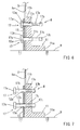
Fig. 4 ] A vertical sectional view of a splitter mounting section according to a second embodiment. This figure shows a state in which fixing tools have been fastened. - [
Fig. 5 ] A vertical sectional view of the splitter mounting section according to the second embodiment. This figure shows a state in which the fixing tools have been loosened. - [
Fig. 6 ] A vertical sectional view of a splitter mounting section according to a third embodiment. This figure shows a state in which fixing tools have been fastened. - [
Fig. 7 ] A vertical sectional view of the splitter mounting section according to the third embodiment. The drawing shows a state in which the fixing tools have been loosened. - Next, embodiments of the present invention will be described with reference to
Figs. 1 through 7 . In the embodiments, a so-called table saw is exemplified as an example of a cutting machine.Fig. 1 is a general view of a cutting machine 1 according to the embodiments. The embodiments are characterized by a structure for preventingfixing tools 13, which fix asplitter 5 to asplitter mounting section 8, from being removed from thesplitter mounting section 8; apart from this, regarding the basic construction of the table saw, a conventionally adopted one suffices, and no particular modification is required in the embodiments. Thus, the overall construction of the cutting machine 1 will be briefly described.
This cutting machine 1 has a table 2, on which workpiece W to be cut is placed, and a cutting machinemain body 10 supported under the table 2. The table 2 is supported horizontally by abase 4. The user is positioned on the right side of the table 2 as seen in the drawing.
The cutting machinemain body 10 has an ascent/descent base 9 supported so as to be capable of vertical parallel ascent/descent movement viaslide shafts 6 provided on thebase 4 along the vertical direction, an electric motor 7 mounted to the ascent/descent base 9, and asaw blade 3 rotating by the electric motor 7 as the drive source. The upper portion of thesaw blade 3 protrudes upwards from substantially the center of the table 2. Through ascent/descent movement of the ascent/descent base 9, it is possible to change the dimension by which thesaw blade 3 protrudes from the upper surface of the table 2 (the cut-in depth with respect to the workpiece W). As indicated by an outline arrow inFig. 1 , thesaw blade 3 rotates clockwise. Thus, the blade edge on the front side in the cutting proceeding direction of the portion of thesaw blade 3 protruding on the upper surface side of the table 2 is displaced upwardly.
The workpiece W is moved in the direction as indicated by the outline arrow (the cutting proceeding direction) with respect to thesaw blade 3 protruding from the upper surface of the table 2, whereby the front side blade edge of thesaw blade 3 is relatively cut into the workpiece W, whereby the workpiece W is cut. A so-called splitter 5 (riving knife) is arranged so as to extend along the blade edge on the front side in the cutting proceeding direction (the left side inFig. 1 ) of thesaw blade 3. - The
splitter 5 is a flat plate of substantially the same thickness as thesaw blade 3, and is supported so as to be flush with thesaw blade 3. Thesplitter 5 is held in the kerf of the workpiece W immediately after cut so as to maintain a fixed width of the kerf, whereby the kerf is prevented from coming into contact with thesaw blade 3 to thereby prevent kickback (a phenomenon in which the kerf of the workpiece W is raised upwards).
Thesplitter 5 is mounted to thesplitter mounting section 8 provided on a lateral side of the ascent/descent base 9. Like thesaw blade 3, thesplitter 5 protrudes from the lower surface side to the upper surface side of the table 2. Thesplitter mounting section 8 is illustrated in detail inFig. 2 and its subsequent figures.
Thesplitter mounting section 8 has asplitter mounting base 11 mounted on the ascent/descent base 9, apressure plate 12, and twofixing tools 13. Thesplitter mounting base 11 is an L-shaped member having ahorizontal base portion 11a and avertical base portion 11b; thehorizontal base portion 11a is fixed to the ascent/descent base 9, and thevertical base portion 11b is fixed in position in a state of being raised upward. The lower portion of thesplitter 5 is held between thevertical base portion 11b and thepressure plate 12.
As thefixing tools 13, there are used hexagonal bolts each having ahexagonal head portion 13a and a threadedshaft portion 13b. In correspondence with the twofixing tools 13, there are provided twoinsertion holes 12a in thepressure plate 12, and two threadedholes 11c are provided in thevertical base portion 11b of thesplitter mounting base 11. The two threadedholes 11c are formed so as to extend through thevertical base portion 11b in the thickness direction.
Further, in the lower portion of thesplitter 5, there is provided a mountinghole 5a in the form of an elongated groove hole. The mountinghole 5a is open at the lower end of thesplitter 5. The twofixing tools 13 are passed through the mountinghole 5a.
The threadedshaft portions 13b of thefixing tools 13 are passed through theinsertion holes 12a of thepressure plate 12 and the mountinghole 5a of thesplitter 5, and are fastened to the threadedholes 11c of thevertical base portion 11b, whereby the lower portion of thesplitter 5 is firmly held between thevertical base portion 11b and thepressure plate 13, so that thesplitter 5 is supported in an uprise state.
Conversely, when the twofixing tools 13 are loosened through rotation in the loosening direction, the holding by thepressure plate 12 is loosened, so that it is possible to adjust the vertical position of thesplitter 5; further, it is possible to remove thesplitter 5 from thesplitter mounting section 8 by pulling it upwards from between thepressure plate 12 and thevertical base portion 11b. - The threaded
shaft portions 13b of thefixing tools 13 are long enough to extend through the threadedholes 11c of thevertical base portion 11b to protrude therefrom. Attached to the protruding ends of the threadedshaft portions 13b are nuts 14 with a loosening preventing function as removal preventing members. Elastic bitingmembers 14a are mounted to the inner peripheral sides (female screw portions) of the nuts 14. Due to their biting action owing to their elasticity, the bitingmembers 14a exert a loosening preventing function on the threadedshaft portions 13b. Thus, as shown inFig. 3 , when the twofixing tools 13 are loosened, the nuts 14 come into contact with the side surface of thevertical base portion 11b, whereby the rotation in the loosening direction of thefixing tools 13 is restricted. In this way, because the rotating operation amount in the loosening direction of the twofixing tools 13 is restricted, removal of the fixing tools from the threadedholes 11c of thevertical base portion 11b is prevented, and therefore, the fixing tools may not be removed from the threadedholes 11c by being excessively loosened.
According to the fixing tool removal prevention structure of the first embodiment constructed as described above, the nuts 14 with a loosening preventing function are attached to thefixing tools 13 to restrict the rotating operation amount in the loosening direction, whereby removal of the fixing tools from the threadedholes 11c is prevented. Thus, for example, in the case that the twofixing tools 13 are loosened in order to perform position adjustment of thesplitter 5, etc., the fixing tools may not be accidentally excessively loosened, so that thefixing tools 13 may not be removed from the threadedholes 11c, whereby it is possible, for example, to quickly perform the subsequent fastening operation, thus enabling an improvement in terms of the workability in the position adjusting operation. - The removal prevention structure according to the first embodiment described above may be modified in various ways. For example, instead of the nuts 14, it is possible to adopt removal preventing means of some other form.
Figs. 4 and 5 show a removal prevention structure according to a second embodiment. Fixingtools 16 according to the second embodiment differ from those of the first embodiment in that stop rings 15 are attached thereto instead of thenuts 14 of the first embodiment. The other respects of this embodiment may be the same as the first embodiment, so the description will be omitted by using the same reference numerals.
The fixing tool removal prevention structure according to the second embodiment also employs twofixing tools 16 each employing a hexagon bolt having ahexagonal head portion 16a and a threadedshaft portion 16b. The stop rings 15 serving as the removal preventing members are attached to the end portions of the threadedshaft portions 16b protruding from the threadedholes 11c. The stop rings 15 are attached to the threadedshaft portions 16b so as not to be displaced in the axial direction.
Also with thefixing tools 16 with the snap rings 15 attached thereto, when they are fastened as shown inFig. 4 , they firmly hold the lower portion of thesplitter 5 between thepressure plate 12 and thevertical base portion 11b, making it possible to support thesplitter 5 in an uprise state. Conversely, when the twofixing tools 16 are loosened as shown inFig. 5 , the holding by thepressure plate 12 is released, making it possible to adjust the position of thesplitter 5. The rotating operation amounts in the loosening direction of the twofixing tools 16 are restricted by the respective stop rings 15. As a result, the user may not rotate the fixing tools accidentally excessively in the loosening direction, so that removal of the twofixing tools 16 from the threadedholes 11c is reliably prevented, thereby securing the workability in the position adjusting operation of thesplitter 5, etc. -
Figs. 6 and 7 show a fixing tool removal prevention structure according to a third embodiment. Fixingtools 17 according to the third embodiment differ from those of the first and second embodiments in that they have unthreadedportions 17c instead of the nuts 14 and the stop rings 15. The other respects of this embodiment may be the same as the first and second embodiments, so the description will be omitted by using the same reference numerals.
The fixing tool removal prevention structure according to the third embodiment also employs twofixing tools 17. As the twofixing tools 17, hexagon bolts each having ahexagonal head portion 17a and a threadedshaft portion 17b are employed. The threadedshaft portions 17b are provided with unthreadedportions 17c devoid of threads. In the third embodiment, the unthreadedportions 17c function as the removal preventing members. The unthreadedportion 17c is provided in a predetermined axial range in a midway of the threadedshaft portion 17b. Thus, a thread is left at the end portion within the range protruding from the threadedhole 11c, with the threadedshaft portions 17b being situated on both sides of the unthreadedportion 17c. As shown inFig. 6 , the unthreadedportions 17c are provided so as to protrude from the threadedholes 11c in a state in which thefixing tools 17 have been firmly fastened.
Further, the unthreadedportions 17c are provided in a length range larger than the thickness of thevertical base portion 11b of thesplitter mounting base 11.
According to the removal prevention structure having the fixingtools 17 constructed as described above, when the twofixing tools 17 are firmly fastened to the threadedholes 11c as shown inFig. 6 , the lower portion of thesplitter 5 is firmly held between thepressure plate 12 and thevertical base portion 11b, and thesplitter 5 is supported so as to be raised upward. Conversely, as shown inFig. 7 , when the twofixing tools 17 are rotated in the loosening direction, the holding by thepressure plate 12 is released, so that it is possible to perform position adjustment of thesplitter 5, etc. The unthreadedportions 17c are respectively provided on the threadedshaft portions 17b of the twofixing tools 17. Therefore, when thefixing tools 17 are rotated in the loosening direction, the unthreadedportions 17c are situated on the inner peripheral sides of the threadedholes 11c, so that the threadedshaft portion 17b are brought not to engage. In this state, thefixing tools 17 rotate idle with respect to the threadedholes 11c, whereby removal of thefixing tools 17 from the threadedholes 11c is prevented. - The embodiments described above may be further modified in various ways. For example, while in the above-described examples the
splitter 5 is fixed in position by using two fixing tools 13 (16, 17), it is also applicable to the case where the fixing is effected by using one or three or more fixing tools.
Further, while the constructions using hexagon bolts as thefixing tools loosening preventing nuts 14, the stop rings 15, or the unthreadedportions 17c. In the case where nuts are used as the fixing tools, it is possible to omit the threadedholes 11c of thevertical base portion 11b.
Further, in the first embodiment, instead of the nuts 14 with a loosening preventing function, two nuts with no special loosening preventing function may be mutually fastened, thus making it possible to achieve the same operation and advantages by so-called double nuts with a loosening preventing function.
Claims (4)
- A removal prevention structure for a cutting machine having a table on which a workpiece to be cut is placed, and a cutting machine main body supported under the table,
wherein the cutting machine main body has a circular saw blade rotated by an electric motor, and a splitter for preventing kickback caused by the saw blade, with an upper portion of the saw blade and an upper portion of the splitter being supported while protruding from an upper surface of the table,
wherein the splitter is supported by a splitter mounting section provided on the cutting machine main body, the splitter mounting section can fix the splitter in an uprise state by by fastening a fixing tool to a splitter mounting base, and the fixing tool can be loosened to allow positional adjustment of the splitter, and
wherein the fixing tool can be fastened and loosened through rotation and has a removal preventing member for preventing removal from the splitter mounting base when loosened. - The removal prevention structure according to claim 1, wherein a fixing screw having a threaded shaft portion is used as the fixing tool.
- The removal prevention structure according to claim 2, wherein the fixing screw has the threaded shaft portion longer than a threaded hole formed in the mounting base to extend therethrough, and wherein a nut with a loosening preventing function is attached to an end portion of the threaded shaft portion protruding from the threaded hole to thereby configure the removal preventing member.
- The removal prevention structure according to claim 2, wherein the fixing screw has a threaded shaft portion longer than a threaded hole formed in the mounting base to extend therethrough, and wherein an unthreaded portion devoid of threads is provided in a midway of the threaded shaft portion over a range longer than the threaded hole to thereby provide the removal preventing member.
Applications Claiming Priority (2)
| Application Number | Priority Date | Filing Date | Title |
|---|---|---|---|
| JP2009102801A JP2010253572A (en) | 2009-04-21 | 2009-04-21 | Structure for preventing falling of fixture of split edge in cutter |
| PCT/JP2010/055666 WO2010122878A1 (en) | 2009-04-21 | 2010-03-30 | Structure for preventing falling off of riving knife fastener for rotary saw |
Publications (2)
| Publication Number | Publication Date |
|---|---|
| EP2422909A1 true EP2422909A1 (en) | 2012-02-29 |
| EP2422909A4 EP2422909A4 (en) | 2015-06-24 |
Family
ID=43011001
Family Applications (1)
| Application Number | Title | Priority Date | Filing Date |
|---|---|---|---|
| EP10766937.6A Withdrawn EP2422909A4 (en) | 2009-04-21 | 2010-03-30 | Structure for preventing falling off of riving knife fastener for rotary saw |
Country Status (5)
| Country | Link |
|---|---|
| US (1) | US20120055302A1 (en) |
| EP (1) | EP2422909A4 (en) |
| JP (1) | JP2010253572A (en) |
| CN (1) | CN202555901U (en) |
| WO (1) | WO2010122878A1 (en) |
Cited By (2)
| Publication number | Priority date | Publication date | Assignee | Title |
|---|---|---|---|---|
| WO2018141512A1 (en) * | 2017-01-31 | 2018-08-09 | Robert Bosch Gmbh | Circular saw, in particular hand-held circular saw |
| US11629319B2 (en) | 2016-06-15 | 2023-04-18 | Mimetas, B.V. | Cell culture device and methods |
Families Citing this family (10)
| Publication number | Priority date | Publication date | Assignee | Title |
|---|---|---|---|---|
| EP2976195B1 (en) * | 2012-12-31 | 2017-08-02 | Robert Bosch GmbH | Table saw with a kickback detection system |
| TWI682821B (en) * | 2015-03-12 | 2020-01-21 | 德商羅伯特博斯奇股份有限公司 | Drop arm reset method |
| US10322522B2 (en) | 2015-03-12 | 2019-06-18 | Robert Bosch Tool Corporation | Electrical configuration for object detection system in a saw |
| US10821529B2 (en) | 2015-03-12 | 2020-11-03 | Robert Bosch Tool Corporation | Power tool with improved belt tensioning |
| US10799964B2 (en) | 2015-03-12 | 2020-10-13 | Robert Bosch Tool Corporation | Table saw with pulley alignment mechanism |
| US10758989B2 (en) | 2015-03-12 | 2020-09-01 | Robert Bosch Tool Corporation | System and method for sensing cable fault detection in a saw |
| US10786854B2 (en) | 2015-03-12 | 2020-09-29 | Robert Bosch Tool Corporation | Table saw with electrically isolated arbor shaft |
| US9969015B2 (en) | 2015-03-12 | 2018-05-15 | Robert Bosch Tool Corporation | Power tool with protected coupling plate |
| CN111237321A (en) * | 2019-12-18 | 2020-06-05 | 深圳巴斯巴科技发展有限公司 | Disassembly-free structure for fixing functional screws |
| DE102020132928A1 (en) | 2020-12-10 | 2022-06-15 | Otto Ganter Gmbh & Co. Kg Normteilefabrik | Spring-loaded indexing bolt |
Family Cites Families (19)
| Publication number | Priority date | Publication date | Assignee | Title |
|---|---|---|---|---|
| US2352235A (en) * | 1941-09-10 | 1944-06-27 | Delta Mfg Co | Saw guard |
| US2530867A (en) * | 1949-03-28 | 1950-11-21 | Galanga Charles | Spreaders for circular saw wood cutting machines |
| US3583450A (en) * | 1969-03-03 | 1971-06-08 | Hartzell Industries | Saw splitter and tipper assembly |
| JPS58111408U (en) * | 1982-01-26 | 1983-07-29 | 株式会社神戸製鋼所 | Detachable device for remote control |
| DE3403762A1 (en) * | 1984-02-03 | 1985-08-14 | Festo KG, 7300 Esslingen | Device for releasably fastening a splitting wedge to a saw |
| US4721023A (en) * | 1986-06-20 | 1988-01-26 | Shopsmith, Inc. | Saw guard system |
| JPH0689770B2 (en) * | 1992-02-20 | 1994-11-14 | 智廣 芳ケ迫 | Male screw removal prevention device |
| JPH0646901U (en) * | 1992-12-11 | 1994-06-28 | ヤマハ株式会社 | Circular saw machine |
| JP2002061626A (en) * | 2000-08-21 | 2002-02-28 | Ishikawajima Harima Heavy Ind Co Ltd | Screw drop prevention mechanism |
| US6840144B2 (en) * | 2002-07-17 | 2005-01-11 | Durq Machinery Corp. | Quick-detachable blade guard mounting structure |
| JP4511853B2 (en) | 2004-03-17 | 2010-07-28 | 株式会社マキタ | Cutting machine riving knife |
| JP4617091B2 (en) * | 2004-03-16 | 2011-01-19 | 株式会社マキタ | Rive knife attachment in a cutting machine |
| US7540223B2 (en) * | 2004-03-12 | 2009-06-02 | Makita Corporation | Mountings for riving knives of table saws |
| JP2007076235A (en) * | 2005-09-15 | 2007-03-29 | Makita Corp | Cutting machine |
| JP4794984B2 (en) * | 2005-11-01 | 2011-10-19 | 株式会社マキタ | Cutting machine |
| US7210386B1 (en) * | 2005-11-02 | 2007-05-01 | Kingsand Machinery Ltd. | Quickly detachable protective cover unit of a table sawing machine |
| US7621204B2 (en) * | 2006-07-25 | 2009-11-24 | Black & Decker Inc. | Riving knife system for table saw |
| US20080276780A1 (en) * | 2007-05-11 | 2008-11-13 | Bor-Yann Chuang | Combining device for the chopper set of a table sawing machine |
| DE102010042016A1 (en) * | 2010-10-06 | 2012-04-12 | Robert Bosch Gmbh | Splitting wedge unit, has fastening unit for releasable fastening at circular saw and formed by screw, which is connected with base body in loss-proof manner, and securing element securing fastening unit at base body |
-
2009
- 2009-04-21 JP JP2009102801A patent/JP2010253572A/en active Pending
-
2010
- 2010-03-30 CN CN2010900008070U patent/CN202555901U/en not_active Expired - Fee Related
- 2010-03-30 WO PCT/JP2010/055666 patent/WO2010122878A1/en not_active Ceased
- 2010-03-30 US US13/263,925 patent/US20120055302A1/en not_active Abandoned
- 2010-03-30 EP EP10766937.6A patent/EP2422909A4/en not_active Withdrawn
Non-Patent Citations (1)
| Title |
|---|
| See references of WO2010122878A1 * |
Cited By (3)
| Publication number | Priority date | Publication date | Assignee | Title |
|---|---|---|---|---|
| US11629319B2 (en) | 2016-06-15 | 2023-04-18 | Mimetas, B.V. | Cell culture device and methods |
| WO2018141512A1 (en) * | 2017-01-31 | 2018-08-09 | Robert Bosch Gmbh | Circular saw, in particular hand-held circular saw |
| US10967537B2 (en) | 2017-01-31 | 2021-04-06 | Robert Bosch Gmbh | Circular saw, in particular hand-held circular saw |
Also Published As
| Publication number | Publication date |
|---|---|
| JP2010253572A (en) | 2010-11-11 |
| CN202555901U (en) | 2012-11-28 |
| WO2010122878A1 (en) | 2010-10-28 |
| US20120055302A1 (en) | 2012-03-08 |
| EP2422909A4 (en) | 2015-06-24 |
Similar Documents
| Publication | Publication Date | Title |
|---|---|---|
| EP2422909A1 (en) | Structure for preventing falling off of riving knife fastener for rotary saw | |
| US8037792B2 (en) | Mountings for riving knives of table saws | |
| RU2557033C2 (en) | Structure for prevention of safety element fastener fallout in cutter | |
| JP5047199B2 (en) | Insert chip and chamfering machine using the same | |
| JP5633007B2 (en) | Cutting machine | |
| TW200615068A (en) | Milling cutter tool, screw thread milling cutter in particular | |
| KR20080095259A (en) | Lock nuts | |
| US20100319509A1 (en) | Quick release device for a chopper in a workbench sawing machine | |
| JP6173627B1 (en) | Cutting tool | |
| CN101875205B (en) | Bench saw | |
| CN109865872B (en) | Milling cutter | |
| CN201483580U (en) | Bench saw | |
| CN210361531U (en) | Knife roller and chopping device with same | |
| CN109604728B (en) | A kind of edge trimming knife, knife holder and photovoltaic edge trimming machine | |
| CN216573449U (en) | Crushing shaft for crusher | |
| KR101624690B1 (en) | Portable corner cutter | |
| KR101088393B1 (en) | Cutter for Pipe Cutting Machine | |
| KR20110010379U (en) | Steel cutting machine | |
| US20100206153A1 (en) | Spreader mounting structure for saw machine | |
| KR0112709Y1 (en) | Cutter clamping device | |
| CN216990175U (en) | Bolt blooming fastening device for carburetor of small gasoline engine | |
| KR200421749Y1 (en) | Tapping device | |
| CN102166762A (en) | Cutting knife device of paper cutter with adjustable cutting knife position | |
| KR100692709B1 (en) | Insert Tip Assembly Structure of Milling Cutter | |
| CN214134163U (en) | A firmly installed milling cutter for CNC machining |
Legal Events
| Date | Code | Title | Description |
|---|---|---|---|
| PUAI | Public reference made under article 153(3) epc to a published international application that has entered the european phase |
Free format text: ORIGINAL CODE: 0009012 |
|
| 17P | Request for examination filed |
Effective date: 20111012 |
|
| AK | Designated contracting states |
Kind code of ref document: A1 Designated state(s): AT BE BG CH CY CZ DE DK EE ES FI FR GB GR HR HU IE IS IT LI LT LU LV MC MK MT NL NO PL PT RO SE SI SK SM TR |
|
| DAX | Request for extension of the european patent (deleted) | ||
| RA4 | Supplementary search report drawn up and despatched (corrected) |
Effective date: 20150521 |
|
| RIC1 | Information provided on ipc code assigned before grant |
Ipc: B27B 5/22 20060101ALI20150515BHEP Ipc: B27G 19/08 20060101ALI20150515BHEP Ipc: F16B 41/00 20060101ALI20150515BHEP Ipc: B23D 45/06 20060101ALI20150515BHEP Ipc: F16B 5/02 20060101ALI20150515BHEP Ipc: B23D 47/00 20060101AFI20150515BHEP Ipc: F16B 39/34 20060101ALI20150515BHEP Ipc: F16B 35/04 20060101ALI20150515BHEP |
|
| 17Q | First examination report despatched |
Effective date: 20170123 |
|
| STAA | Information on the status of an ep patent application or granted ep patent |
Free format text: STATUS: THE APPLICATION IS DEEMED TO BE WITHDRAWN |
|
| 18D | Application deemed to be withdrawn |
Effective date: 20171206 |