EP2422646B1 - Folding camping table - Google Patents
Folding camping table Download PDFInfo
- Publication number
- EP2422646B1 EP2422646B1 EP11170428.4A EP11170428A EP2422646B1 EP 2422646 B1 EP2422646 B1 EP 2422646B1 EP 11170428 A EP11170428 A EP 11170428A EP 2422646 B1 EP2422646 B1 EP 2422646B1
- Authority
- EP
- European Patent Office
- Prior art keywords
- legs
- configuration
- leg
- table top
- folding camp
- Prior art date
- Legal status (The legal status is an assumption and is not a legal conclusion. Google has not performed a legal analysis and makes no representation as to the accuracy of the status listed.)
- Active
Links
Images


Classifications
-
- A—HUMAN NECESSITIES
- A47—FURNITURE; DOMESTIC ARTICLES OR APPLIANCES; COFFEE MILLS; SPICE MILLS; SUCTION CLEANERS IN GENERAL
- A47B—TABLES; DESKS; OFFICE FURNITURE; CABINETS; DRAWERS; GENERAL DETAILS OF FURNITURE
- A47B3/00—Folding or stowable tables
- A47B3/02—Folding or stowable tables with foldable cross legs
-
- A—HUMAN NECESSITIES
- A47—FURNITURE; DOMESTIC ARTICLES OR APPLIANCES; COFFEE MILLS; SPICE MILLS; SUCTION CLEANERS IN GENERAL
- A47B—TABLES; DESKS; OFFICE FURNITURE; CABINETS; DRAWERS; GENERAL DETAILS OF FURNITURE
- A47B13/00—Details of tables or desks
- A47B13/003—Connecting table tops to underframes
Definitions
- the present invention relates to a folding table, particularly but without limitation a camp table as defined in the preamble of claim 1.
- a folding table is disclosed for instance in US 1, 608,924 A .
- Camp tables which have a table top and a frame with two pairs of X-shaped (crossed) legs adapted to support the table top.
- these tables are adapted to be folded, which means that they can be changed from an operating configuration to a rest configuration.
- such tables have pivoting means, at the crossing point of each pair of legs, that can allow the pairs of legs to be folded for size reduction and easier transportation and storage of the table when the latter is not being used. While these tables have undoubted advantages, such as light weight, compact size, etc., they still suffer from certain drawbacks, especially the one concerning stability during use.
- the object of the present invention is to provide a folding table that can solve the above mentioned prior art drawback.
- this object is fulfilled by a folding table as defined in claim 1.
- the present invention provides a folding table that can be used for outdoor activities, such as camping and picnicking but also for indoor activities.
- numeral 1 generally designates a folding table when it is in a first configuration, i.e. in a configuration that is typically suitable for proper operation thereof.
- this table 1 is adapted for use in outdoor activities, such as camping, but it can be also used for indoor activities.
- the table 1 comprises a table top 2 having a first side 2A and a second side 2B at the larger opposed surfaces.
- the first 2A and second 2B sides of the table top 2 are joined by a shoulder 2C.
- the table top 2 preferably consists of a substantially rectangular surface, where the linear extension of the shoulder 2C is considerably smaller than the linear extension of the first side 2A or the second side 2B.
- the first side 2A is the side designed as an object supporting shelf.
- the table 1 comprises a frame 3 having:
- the support elements 4, 5 are preferably arranged along one edge of the first side 2A or the second side 2B and preferably, if the table top 2 consists of a rectangular surface, along the edge with the larger linear dimension. Therefore, such support elements 4, 5 at least partially delimit the perimeter of the top plane 2.
- each set of crossed legs 6, 7 comprises two legs 6A, 6B and 7A, 7B respectively, preferably made of aluminum.
- the crossing portion of the two legs 6A, 6B and/or 7A, 7B of each set of crossed legs 6, 7 comprises first pivoting means 9 which are adapted to change the table 1 from the first operating configuration ( Figure 1 ) to a second rest configuration ( Figure 7 ).
- one of the two legs (the one referenced 6B or 7B) is formed of one piece, whereas the other leg (the one referenced 6A or 7A) is made up of two portions, which are joined together by the first pivoting means 9.
- the pivoting means 9 comprise:
- the pair of connecting rods 9A, 9B has a S shape, since the axes along which the two portions 6A', 6A" of the leg 6A (or the portions 7A', 7A" of the leg 7A) extend are parallel but not coincident.
- each support element 4, 5 comprises:
- the angle of inclination ⁇ is an obtuse angle falling within a range from 130° to 140°, and is preferably 135°.
- the first portion 4A, 5A ends with a first side 10 which is adapted to support the table top 2, i.e. the side opposed to the one designed to support the objects required for camping, e.g. the side 2B.
- the second portion 4B, 5B ends with a second side 11, which is adapted to abut against a leading end 6', 7' of each set of crossed legs 6, 7 when said table 1 is in the first configuration or operating configuration ( Figure 1 ) .
- the second side 11 extends in a direction of extension X-X substantially normal to the direction of extension Z-Z of the second portion 4B, 5B.
- the second side 11 has a flat surface.
- the second portion 4B, 5B extends or projects from the first portion 4A, 5A.
- each leg 6A, 6B and 7A, 7B abuts against the second side 11 to create a form fit, as the leading end 6', 7' also ends by a flat surface.
- the second portion 4B, 5B is inclined at an angle ⁇ of 135°, then the side 11 is inclined at an angle ⁇ of 45°. This ensures that the release of forces causes no torque between the ends 6', 7' of the legs 6A, 6B and 7A, 7B and the support elements 4, 5 when the table 1 is loaded. Furthermore, also preferably, the first portion 4A, 5A and the second portion 4B, 5B of each support element 6, 7 are formed of one piece.
- the support element consists of a hollow tubular member, preferably formed by extrusion of aluminum.
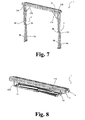
- the table 1 may comprise second pivoting means 12 for changing the table from the second configuration ( Figure 7 ) to a third configuration ( Figure 8 ) in which the legs 6A, 6B and 7A, 7B of each set of crossed legs 6, 7 extend substantially parallel to the larger opposed surfaces of the first 2A and second 2B sides of the table top 2.
- the second pivoting means 12 include a pair of L-shaped connecting rods 12A, 12b and a pivot pin 12C for each leg 6A, 6B, 7A and/or 7B of said set of crossed legs 6, 7.
- the long side of the L shape is coupled by said pivot pin 12C to the second portion 4B, 5B of the support element to pivot about the axis of said pin 12C and the short side of the L shape is coupled by retaining means 12D to the corresponding leg.
- the short side of the L shape is located proximate to the leading end 6', 7' of each leg 6A, 7A, 6B and/or 7B.
- the retaining means 12D consist of bolts or rivets or similar elements.
- first side 11 of the first portion comprises a seat 13 which is configured to support the table top 2.
- the seat 13 comprises:
- connection/disconnection means 14 ( Figure 2 ) are provided, which can hold the table top 2 when the table 1 is being used, and can allow removal of the table top 2 when the table 1 changes to the second or rest configuration ( Figure 7 ).
- connection/disconnection means 14 consist, for instance, of a pin that engages at one end the support element 4, 5 (preferably the first portion 4A, 5A of the support element) and at the other end the table top 2 (preferably the shoulder 2C of the table top) .
- connection/disconnection means 14 is designed to be controlled, for instance, by a button 14B pressed by the user; such button 14B is operably connected to the pin through an elastic member, such as a spring (not shown).
- connection/disconnection means 14 hold the table top 2 in the seat 13 whereas, as the user presses the button 14B, the elastic load of the elastic elements is overcome, the table top 2 is released from any restraint and may be removed from the seat.
- the table top 2 consists of a shutter that is preferably of the folding type ( Figure 6 ) .
- connection/disconnection means 14 preferably acts upon a shutter element that is the one at one leading end of the shutter.
- the shutter comprises a plurality of independent elements, preferably having identical shapes and sizes, and joined together by a fine cord that ensures retention thereof.
- the plurality of elements that form the shutter are formed in such a manner as to leave no gap between elements, and create a perfectly smooth table top 2.
- the shutter is made of aluminum.
- a table 1 may comprise a height adjustment device 15 located at least at one trailing end of a leg 6A, 6B, 7A, 7B, said trailing end being opposite to the leading end 6', 7' .
- Such height adjustment device 15 allows compensation for any flatness imperfection in the floor surface, to prevent any undesirable leaning of the table 1 when the latter is in the first configuration ( Figure 1 ) and is under dynamic load.
- the table 1 may include a cross member 16 extending between the two crossing areas of the pairs of legs 6, 7. Such cross member 16 imparts better stability to the table 1.
- the table 1 may comprise a pair of articulated elements 17A, 17B, each extending between the leading end 6', 7' of each leg 6A, 6B, 7A, 7B and the first portion 4A, 5A of the support element 4 or 5 respectively.
- the pair of articulated elements 17A, 17B are located at the apices of a diagonal of the table top 2.
- Each articulated element 17A, 17B comprises a pivot pin 17C.
- Such articulated elements 17A, 17B assist the change from the second configuration to the third configuration of the table 1 and increase the stability of the table, when the latter is in the first configuration.
- connection/disconnection means 14 shall be operated to release the pin from engagement with the support element 4, 5, and lift the cross member 16 in a removal direction substantially perpendicular to the floor surface.
- the table top 2 so folded may be removed and placed outside the frame 3, e.g. on the floor surface ( Figure 6 ) .
- leg 6A or 7A will pivot about the axis of the pivot pin 9D relative to the leg 6B or 7B respectively ( Figure 7 ), to reach the second configuration of the table 1.
- each pair of legs 6, 7 is further moved towards the support elements 4, 5, it will rotate about the axis of the pivot pin 12C to reach the third configuration in which said pairs of legs 6, 7 extend substantially parallel to the first and/or the second side 2A, 2B.
Landscapes
- Tables And Desks Characterized By Structural Shape (AREA)
- Motorcycle And Bicycle Frame (AREA)
Description
- The present invention relates to a folding table, particularly but without limitation a camp table as defined in the preamble of claim 1.
- A folding table is disclosed for instance in
US 1, 608,924 A . - Camp tables are known which have a table top and a frame with two pairs of X-shaped (crossed) legs adapted to support the table top.
- Particularly, these tables are adapted to be folded, which means that they can be changed from an operating configuration to a rest configuration. For this purpose, such tables have pivoting means, at the crossing point of each pair of legs, that can allow the pairs of legs to be folded for size reduction and easier transportation and storage of the table when the latter is not being used. While these tables have undoubted advantages, such as light weight, compact size, etc., they still suffer from certain drawbacks, especially the one concerning stability during use.
- In the light of the above prior art, the object of the present invention is to provide a folding table that can solve the above mentioned prior art drawback.
- According to the present invention, this object is fulfilled by a folding table as defined in claim 1.
- The present invention provides a folding table that can be used for outdoor activities, such as camping and picnicking but also for indoor activities.
- The characteristics and advantages of the invention will appear from the following detailed description of one practical embodiment, which is illustrated without limitation in the annexed drawings, in which:
-
Figure 1 shows a perspective view of the table of the present invention; -
Figure 2 shows a partial side view of a portion of the table ofFigure 1 ; -
Figure 3 shows a lateral section of a of a portion of a support element for supporting the table ofFigure 1 ; -
Figures 4 to 8 show the steps required for changing the table ofFigure 1 from the first (operating) configuration to a third (minimum size) configuration (Figure 8 ) through a second (rest) configuration (Figure 7 ) . - Referring to the accompanying figures, numeral 1 generally designates a folding table when it is in a first configuration, i.e. in a configuration that is typically suitable for proper operation thereof. Preferably, this table 1 is adapted for use in outdoor activities, such as camping, but it can be also used for indoor activities.
- The table 1 comprises a
table top 2 having afirst side 2A and asecond side 2B at the larger opposed surfaces. The first 2A and second 2B sides of thetable top 2 are joined by ashoulder 2C. - The
table top 2 preferably consists of a substantially rectangular surface, where the linear extension of theshoulder 2C is considerably smaller than the linear extension of thefirst side 2A or thesecond side 2B. - For instance, the
first side 2A is the side designed as an object supporting shelf. - The table 1 comprises a
frame 3 having: - two
support elements table top 2 and - two sets of
crossed legs support elements Figure 1 ). - The
support elements first side 2A or thesecond side 2B and preferably, if thetable top 2 consists of a rectangular surface, along the edge with the larger linear dimension. Therefore,such support elements top plane 2. - Particularly, each set of
crossed legs legs - In one preferred embodiment, the crossing portion of the two
legs crossed legs Figure 1 ) to a second rest configuration (Figure 7 ). - It will be immediately noted, as explained in greater detail with reference to
Figures 4 to 8 , that removal of thetable top 2 is required to change from the first operating configuration, as shown inFigure 1 , to the second rest configuration, as shown inFigure 7 . - For instance, one of the two legs (the one referenced 6B or 7B) is formed of one piece, whereas the other leg (the one referenced 6A or 7A) is made up of two portions, which are joined together by the first pivoting means 9. Thus, for each
leg portions 6A', 6A" or 7A', 7A" , the pivoting means 9 comprise: - a pair of connecting
rods leg - a pivot pin 9D for allowing rotation of said
leg leg - The pair of connecting
rods portions 6A', 6A" of theleg 6A (or theportions 7A', 7A" of theleg 7A) extend are parallel but not coincident. - Advantageously, also referring to
Figure 3 , eachsupport element - a
first portion 4A, 5A that extends in a direction of extension Y-Y substantially perpendicular to the opposed larger surfaces of the first orsecond side table top 2 and - a
second portion 4B, 5B that extends in a direction of extension Z-Z which is inclined at an angle of inclination α to the direction of extension Y-Y of thefirst portion 4A, 5A. - According to a preferred embodiment, the angle of inclination α is an obtuse angle falling within a range from 130° to 140°, and is preferably 135°.
- Particularly, the
first portion 4A, 5A ends with afirst side 10 which is adapted to support thetable top 2, i.e. the side opposed to the one designed to support the objects required for camping, e.g. theside 2B. - It shall be noted that, also referring to
Figure 2 , thesecond portion 4B, 5B ends with asecond side 11, which is adapted to abut against a leading end 6', 7' of each set ofcrossed legs Figure 1 ) . - Preferably, the
second side 11 extends in a direction of extension X-X substantially normal to the direction of extension Z-Z of thesecond portion 4B, 5B. - In a preferred embodiment, the
second side 11 has a flat surface. - Preferably, the
second portion 4B, 5B extends or projects from thefirst portion 4A, 5A. - In other words, the leading end 6', 7' of each
leg second side 11 to create a form fit, as the leading end 6', 7' also ends by a flat surface. - If the
second portion 4B, 5B is inclined at an angle α of 135°, then theside 11 is inclined at an angle β of 45°. This ensures that the release of forces causes no torque between the ends 6', 7' of thelegs support elements first portion 4A, 5A and thesecond portion 4B, 5B of eachsupport element - In other words, the support element consists of a hollow tubular member, preferably formed by extrusion of aluminum.
- The table 1 may comprise second pivoting means 12 for changing the table from the second configuration (
Figure 7 ) to a third configuration (Figure 8 ) in which thelegs crossed legs table top 2. Particularly, the second pivoting means 12 include a pair of L-shaped connectingrods 12A, 12b and apivot pin 12C for eachleg crossed legs - Preferably, for each
leg pivot pin 12C to thesecond portion 4B, 5B of the support element to pivot about the axis of saidpin 12C and the short side of the L shape is coupled byretaining means 12D to the corresponding leg. - It shall be noted that the short side of the L shape is located proximate to the leading end 6', 7' of each
leg - The retaining means 12D consist of bolts or rivets or similar elements.
- Still referring to
Figure 3 , it shall be noted that thefirst side 11 of the first portion comprises aseat 13 which is configured to support thetable top 2. - In the embodiment as shown in
Figure 2 , theseat 13 comprises: - a bottom 13A, e.g. having a flat surface and
- a
shoulder 13B, preferably orthogonal to such bottom 13A, for firm support of theside 2B of the top 2 (if theside 2A of thetable top 2 is the one designed to support the objects). - In order to secure the
table top 2 to theseat 13 connection/disconnection means 14 (Figure 2 ) are provided, which can hold thetable top 2 when the table 1 is being used, and can allow removal of thetable top 2 when the table 1 changes to the second or rest configuration (Figure 7 ). - For this purpose, the connection/disconnection means 14 consist, for instance, of a pin that engages at one end the
support element 4, 5 (preferably thefirst portion 4A, 5A of the support element) and at the other end the table top 2 (preferably theshoulder 2C of the table top) . - The pin of the connection/disconnection means 14 is designed to be controlled, for instance, by a
button 14B pressed by the user;such button 14B is operably connected to the pin through an elastic member, such as a spring (not shown). - In other words, when the elastic member exerts its action on the pin, the connection/disconnection means 14 hold the
table top 2 in theseat 13 whereas, as the user presses thebutton 14B, the elastic load of the elastic elements is overcome, thetable top 2 is released from any restraint and may be removed from the seat. - In a preferred embodiment, the
table top 2 consists of a shutter that is preferably of the folding type (Figure 6 ) . - Particularly, the pin of the connection/disconnection means 14 preferably acts upon a shutter element that is the one at one leading end of the shutter.
- It shall be noted that the shutter comprises a plurality of independent elements, preferably having identical shapes and sizes, and joined together by a fine cord that ensures retention thereof.
- It shall be noted that in the first operating configuration of the table 1, the plurality of elements that form the shutter are formed in such a manner as to leave no gap between elements, and create a perfectly
smooth table top 2. - Preferably, the shutter is made of aluminum.
- A table 1 may comprise a
height adjustment device 15 located at least at one trailing end of aleg - Such
height adjustment device 15 allows compensation for any flatness imperfection in the floor surface, to prevent any undesirable leaning of the table 1 when the latter is in the first configuration (Figure 1 ) and is under dynamic load. - The table 1 may include a
cross member 16 extending between the two crossing areas of the pairs oflegs Such cross member 16 imparts better stability to the table 1. - The table 1 may comprise a pair of articulated
elements leg first portion 4A, 5A of thesupport element - Preferably, the pair of articulated
elements table top 2. Each articulatedelement pivot pin 17C. - Such articulated
elements - Referring now to
Figures 4 to 8 , it shall be noted that the change of the table 1 from the first configuration to the second configuration requires first removal of thetable top 2 and then removal of thecross member 16. - For this purpose, the connection/disconnection means 14 shall be operated to release the pin from engagement with the
support element cross member 16 in a removal direction substantially perpendicular to the floor surface. - Once the
table top 2 has been released from theframe 3, the elements of thetable top 2 may be packed together; therefore, the shutter will be folded as shown inFigure 5 . - Then, the
table top 2 so folded may be removed and placed outside theframe 3, e.g. on the floor surface (Figure 6 ) . - Now, as the two
support elements leg leg Figure 7 ), to reach the second configuration of the table 1. - Finally, as each pair of
legs support elements pivot pin 12C to reach the third configuration in which said pairs oflegs second side - Those skilled in the art will obviously appreciate that a number of changes and variants may be made to the arrangements as described hereinbefore to meet specific needs, without departure from the scope of the invention, as defined in the following claims.
Claims (10)
- A folding camp table (1) comprising:- a table top (2) having a first side (2A) and a second side (2B) at the larger opposed surfaces,- a frame (3) having:characterized in that, when said table (1) is in said first configuration, each support element (4, 5) comprises a first portion (4A, 5A) that extends in a direction of extension (Y-Y) substantially perpendicular to the surfaces of said first (2A) or second side (2B) and a second portion (4B, 5B), that extends in a transverse direction of extension (Z-Z), with an angle of inclination (α) to the direction of extension (Y-Y) of said first portion (4A, 5A), said first portion (4A, 5A) ending by a first side (10) adapted to support said table top (2) and said second portion (4B, 5B) ending by a second side (11) adapted to abut against a corresponding leading end (6', 7') of each leg of said set of crossed legs, said second side (11) extending in a direction of extension (X-X) substantially normal to the direction of extension (Z-Z) of said second portion (4B, 5B).- two support elements (4,5) for supporting said table top (2)- two sets of crossed legs (6, 7) for supporting said two support elements (4, 5) at a preset height, when said table (1) is in a first configuration, each set of crossed legs (6, 7) being composed of two legs (6A, 6B, 7A, 7B),- first pivoting means (9) adapted to move said table (1) from said first configuration to a second configuration, said first pivoting means (9) being located near the crossing portion of said two legs (6A, 6B, 7A, 7B) of each set of legs (6, 7);
- A folding camp table as claimed in claim 1, wherein said angle of inclination (α) is an obtuse angle falling within a range from 130° to 140°, and is preferably 135°.
- A folding camp table as claimed in claim 1 or 2, wherein said first side (10) of said first portion (4A, 5A) comprises a seat (13) which is configured to support said table top (2) and said second side (11) of said second portion (4B, 5B) has a flat surface.
- A folding camp table as claimed in claim 1 or 3, wherein said second portion (4B, 5B) extends from said first portion (4A, 5A), and said first portion (4A, 5A) and said second portion (4B, 5B) of each support element are formed of one piece.
- A folding camp table as claimed in any preceding claim, comprising second pivoting means (12) adapted to move said table (1) from said second configuration to a third configuration in which said two legs (6A, 6B, 7A, 7B) of each set of legs (6, 7) extend substantially parallel to the opposed larger surfaces of said table top (2).
- A folding camp table as claimed in claim 4, wherein said second pivoting means (12) comprise, for each leg (6A, 6B, 7A, 7B) of each set of legs (6, 7) :- a pair of L-shaped connecting rods (12A, 12B) and- a pivot pin (12C),wherein the long side of the L is coupled by said pivot pin (12C) to the second portion (4B, 5B) of said support element (4, 5) to pivot about the axis of said pivot pin and the short side of the L is coupled by retaining means (12D) to the leading end (6', 7') of the corresponding leg (6A, 6B, 7A, 7B).
- A folding camp table as claimed in claim 1, wherein said table top (2) comprises a collapsible shutter.
- A folding camp table as claimed in claim 1, comprising a height adjustment device (15) located at least at one trailing end of a leg (6A, 6B, 7A, 7B), said trailing end being opposite to the leading end.
- A folding camp table as claimed in claim 1, comprising a crossbar (16) extending between said crossing areas of said two sets of crossed legs (6, 7).
- A folding camp table as claimed in claim 1, comprising a pair of articulated elements (17A, 17B), each extending between the leading end (6', 7') of each leg (6A, 6B, 7A, 7B) and the first portion (4A, 5A) of each support element (4, 5).
Applications Claiming Priority (1)
| Application Number | Priority Date | Filing Date | Title |
|---|---|---|---|
| ITMI2010A001568A IT1401534B1 (en) | 2010-08-24 | 2010-08-24 | FOLDABLE CAMPING TABLE |
Publications (2)
| Publication Number | Publication Date |
|---|---|
| EP2422646A1 EP2422646A1 (en) | 2012-02-29 |
| EP2422646B1 true EP2422646B1 (en) | 2015-07-29 |
Family
ID=43739536
Family Applications (1)
| Application Number | Title | Priority Date | Filing Date |
|---|---|---|---|
| EP11170428.4A Active EP2422646B1 (en) | 2010-08-24 | 2011-06-17 | Folding camping table |
Country Status (2)
| Country | Link |
|---|---|
| EP (1) | EP2422646B1 (en) |
| IT (1) | IT1401534B1 (en) |
Cited By (1)
| Publication number | Priority date | Publication date | Assignee | Title |
|---|---|---|---|---|
| US9848695B1 (en) | 2017-01-09 | 2017-12-26 | Gsi Outdoors, Inc. | Spring table |
Family Cites Families (3)
| Publication number | Priority date | Publication date | Assignee | Title |
|---|---|---|---|---|
| US1608924A (en) * | 1921-09-06 | 1926-11-30 | Gold Medal Camp Furniture Mfg | Folding table and the like |
| US1833177A (en) * | 1929-07-15 | 1931-11-24 | Leon J Baker | Adjustable nursery and camp table |
| US4210085A (en) * | 1977-06-14 | 1980-07-01 | Mclravy Robert C Ii | Folding article of furniture |
-
2010
- 2010-08-24 IT ITMI2010A001568A patent/IT1401534B1/en active
-
2011
- 2011-06-17 EP EP11170428.4A patent/EP2422646B1/en active Active
Cited By (1)
| Publication number | Priority date | Publication date | Assignee | Title |
|---|---|---|---|---|
| US9848695B1 (en) | 2017-01-09 | 2017-12-26 | Gsi Outdoors, Inc. | Spring table |
Also Published As
| Publication number | Publication date |
|---|---|
| ITMI20101568A1 (en) | 2012-02-25 |
| EP2422646A1 (en) | 2012-02-29 |
| IT1401534B1 (en) | 2013-07-26 |
Similar Documents
| Publication | Publication Date | Title |
|---|---|---|
| US8182032B2 (en) | Table and seating apparatus | |
| US8820826B2 (en) | Table and seating apparatus | |
| US20160324327A1 (en) | Foldable Bed Frame | |
| US20170340100A1 (en) | Foldable Banquet Table and Bench Set | |
| US8814261B2 (en) | Adirondack chair with double fulcrum | |
| MX2008013417A (en) | Table and seating arrangement. | |
| US7168372B2 (en) | Expandable and collapsible table | |
| AU4158796A (en) | Mobile folding stage | |
| WO1998024342A1 (en) | Folding table | |
| US7584575B2 (en) | Variable height fold and roll staging and method of assembling same | |
| US10986961B2 (en) | Collapsible support stand | |
| KR101510292B1 (en) | Simply portable table | |
| EP2422646A1 (en) | Folding camping table | |
| US20210045538A1 (en) | Bed frame | |
| US6865985B2 (en) | Foldable panel supporter | |
| KR101691057B1 (en) | Table-chair | |
| US11330906B1 (en) | Folding chair | |
| EP3445208B1 (en) | Collapsible table | |
| CN213281952U (en) | Folding table | |
| US6955396B2 (en) | Self stabilizing and shock absorbing folding picnic table support structure | |
| KR102124294B1 (en) | Folding table | |
| US20230397718A1 (en) | Folding Table | |
| KR20130038273A (en) | Folding table frame | |
| CN221204464U (en) | Folding supporting mechanism and folding table | |
| GB2194732A (en) | Table |
Legal Events
| Date | Code | Title | Description |
|---|---|---|---|
| AK | Designated contracting states |
Kind code of ref document: A1 Designated state(s): AL AT BE BG CH CY CZ DE DK EE ES FI FR GB GR HR HU IE IS IT LI LT LU LV MC MK MT NL NO PL PT RO RS SE SI SK SM TR |
|
| AX | Request for extension of the european patent |
Extension state: BA ME |
|
| PUAI | Public reference made under article 153(3) epc to a published international application that has entered the european phase |
Free format text: ORIGINAL CODE: 0009012 |
|
| 17P | Request for examination filed |
Effective date: 20120308 |
|
| GRAP | Despatch of communication of intention to grant a patent |
Free format text: ORIGINAL CODE: EPIDOSNIGR1 |
|
| RIC1 | Information provided on ipc code assigned before grant |
Ipc: A47B 13/00 20060101ALI20150325BHEP Ipc: A47B 3/02 20060101AFI20150325BHEP Ipc: A47B 37/04 20060101ALI20150325BHEP |
|
| INTG | Intention to grant announced |
Effective date: 20150424 |
|
| GRAS | Grant fee paid |
Free format text: ORIGINAL CODE: EPIDOSNIGR3 |
|
| GRAA | (expected) grant |
Free format text: ORIGINAL CODE: 0009210 |
|
| AK | Designated contracting states |
Kind code of ref document: B1 Designated state(s): AL AT BE BG CH CY CZ DE DK EE ES FI FR GB GR HR HU IE IS IT LI LT LU LV MC MK MT NL NO PL PT RO RS SE SI SK SM TR |
|
| REG | Reference to a national code |
Ref country code: GB Ref legal event code: FG4D |
|
| REG | Reference to a national code |
Ref country code: CH Ref legal event code: EP |
|
| REG | Reference to a national code |
Ref country code: AT Ref legal event code: REF Ref document number: 738586 Country of ref document: AT Kind code of ref document: T Effective date: 20150815 |
|
| REG | Reference to a national code |
Ref country code: IE Ref legal event code: FG4D |
|
| REG | Reference to a national code |
Ref country code: DE Ref legal event code: R096 Ref document number: 602011018162 Country of ref document: DE |
|
| REG | Reference to a national code |
Ref country code: AT Ref legal event code: MK05 Ref document number: 738586 Country of ref document: AT Kind code of ref document: T Effective date: 20150729 |
|
| REG | Reference to a national code |
Ref country code: LT Ref legal event code: MG4D |
|
| REG | Reference to a national code |
Ref country code: NL Ref legal event code: MP Effective date: 20150729 |
|
| PG25 | Lapsed in a contracting state [announced via postgrant information from national office to epo] |
Ref country code: NO Free format text: LAPSE BECAUSE OF FAILURE TO SUBMIT A TRANSLATION OF THE DESCRIPTION OR TO PAY THE FEE WITHIN THE PRESCRIBED TIME-LIMIT Effective date: 20151029 Ref country code: LV Free format text: LAPSE BECAUSE OF FAILURE TO SUBMIT A TRANSLATION OF THE DESCRIPTION OR TO PAY THE FEE WITHIN THE PRESCRIBED TIME-LIMIT Effective date: 20150729 Ref country code: GR Free format text: LAPSE BECAUSE OF FAILURE TO SUBMIT A TRANSLATION OF THE DESCRIPTION OR TO PAY THE FEE WITHIN THE PRESCRIBED TIME-LIMIT Effective date: 20151030 Ref country code: LT Free format text: LAPSE BECAUSE OF FAILURE TO SUBMIT A TRANSLATION OF THE DESCRIPTION OR TO PAY THE FEE WITHIN THE PRESCRIBED TIME-LIMIT Effective date: 20150729 Ref country code: FI Free format text: LAPSE BECAUSE OF FAILURE TO SUBMIT A TRANSLATION OF THE DESCRIPTION OR TO PAY THE FEE WITHIN THE PRESCRIBED TIME-LIMIT Effective date: 20150729 |
|
| PG25 | Lapsed in a contracting state [announced via postgrant information from national office to epo] |
Ref country code: AT Free format text: LAPSE BECAUSE OF FAILURE TO SUBMIT A TRANSLATION OF THE DESCRIPTION OR TO PAY THE FEE WITHIN THE PRESCRIBED TIME-LIMIT Effective date: 20150729 Ref country code: RS Free format text: LAPSE BECAUSE OF FAILURE TO SUBMIT A TRANSLATION OF THE DESCRIPTION OR TO PAY THE FEE WITHIN THE PRESCRIBED TIME-LIMIT Effective date: 20150729 Ref country code: PL Free format text: LAPSE BECAUSE OF FAILURE TO SUBMIT A TRANSLATION OF THE DESCRIPTION OR TO PAY THE FEE WITHIN THE PRESCRIBED TIME-LIMIT Effective date: 20150729 Ref country code: PT Free format text: LAPSE BECAUSE OF FAILURE TO SUBMIT A TRANSLATION OF THE DESCRIPTION OR TO PAY THE FEE WITHIN THE PRESCRIBED TIME-LIMIT Effective date: 20151130 Ref country code: HR Free format text: LAPSE BECAUSE OF FAILURE TO SUBMIT A TRANSLATION OF THE DESCRIPTION OR TO PAY THE FEE WITHIN THE PRESCRIBED TIME-LIMIT Effective date: 20150729 Ref country code: ES Free format text: LAPSE BECAUSE OF FAILURE TO SUBMIT A TRANSLATION OF THE DESCRIPTION OR TO PAY THE FEE WITHIN THE PRESCRIBED TIME-LIMIT Effective date: 20150729 Ref country code: SE Free format text: LAPSE BECAUSE OF FAILURE TO SUBMIT A TRANSLATION OF THE DESCRIPTION OR TO PAY THE FEE WITHIN THE PRESCRIBED TIME-LIMIT Effective date: 20150729 Ref country code: IS Free format text: LAPSE BECAUSE OF FAILURE TO SUBMIT A TRANSLATION OF THE DESCRIPTION OR TO PAY THE FEE WITHIN THE PRESCRIBED TIME-LIMIT Effective date: 20151129 |
|
| PG25 | Lapsed in a contracting state [announced via postgrant information from national office to epo] |
Ref country code: NL Free format text: LAPSE BECAUSE OF FAILURE TO SUBMIT A TRANSLATION OF THE DESCRIPTION OR TO PAY THE FEE WITHIN THE PRESCRIBED TIME-LIMIT Effective date: 20150729 |
|
| PG25 | Lapsed in a contracting state [announced via postgrant information from national office to epo] |
Ref country code: EE Free format text: LAPSE BECAUSE OF FAILURE TO SUBMIT A TRANSLATION OF THE DESCRIPTION OR TO PAY THE FEE WITHIN THE PRESCRIBED TIME-LIMIT Effective date: 20150729 Ref country code: CZ Free format text: LAPSE BECAUSE OF FAILURE TO SUBMIT A TRANSLATION OF THE DESCRIPTION OR TO PAY THE FEE WITHIN THE PRESCRIBED TIME-LIMIT Effective date: 20150729 Ref country code: DK Free format text: LAPSE BECAUSE OF FAILURE TO SUBMIT A TRANSLATION OF THE DESCRIPTION OR TO PAY THE FEE WITHIN THE PRESCRIBED TIME-LIMIT Effective date: 20150729 Ref country code: SK Free format text: LAPSE BECAUSE OF FAILURE TO SUBMIT A TRANSLATION OF THE DESCRIPTION OR TO PAY THE FEE WITHIN THE PRESCRIBED TIME-LIMIT Effective date: 20150729 |
|
| REG | Reference to a national code |
Ref country code: DE Ref legal event code: R097 Ref document number: 602011018162 Country of ref document: DE |
|
| PG25 | Lapsed in a contracting state [announced via postgrant information from national office to epo] |
Ref country code: RO Free format text: LAPSE BECAUSE OF FAILURE TO SUBMIT A TRANSLATION OF THE DESCRIPTION OR TO PAY THE FEE WITHIN THE PRESCRIBED TIME-LIMIT Effective date: 20150729 |
|
| PLBE | No opposition filed within time limit |
Free format text: ORIGINAL CODE: 0009261 |
|
| STAA | Information on the status of an ep patent application or granted ep patent |
Free format text: STATUS: NO OPPOSITION FILED WITHIN TIME LIMIT |
|
| REG | Reference to a national code |
Ref country code: FR Ref legal event code: PLFP Year of fee payment: 6 |
|
| 26N | No opposition filed |
Effective date: 20160502 |
|
| PG25 | Lapsed in a contracting state [announced via postgrant information from national office to epo] |
Ref country code: SI Free format text: LAPSE BECAUSE OF FAILURE TO SUBMIT A TRANSLATION OF THE DESCRIPTION OR TO PAY THE FEE WITHIN THE PRESCRIBED TIME-LIMIT Effective date: 20150729 |
|
| PG25 | Lapsed in a contracting state [announced via postgrant information from national office to epo] |
Ref country code: BE Free format text: LAPSE BECAUSE OF FAILURE TO SUBMIT A TRANSLATION OF THE DESCRIPTION OR TO PAY THE FEE WITHIN THE PRESCRIBED TIME-LIMIT Effective date: 20150729 |
|
| PG25 | Lapsed in a contracting state [announced via postgrant information from national office to epo] |
Ref country code: MC Free format text: LAPSE BECAUSE OF FAILURE TO SUBMIT A TRANSLATION OF THE DESCRIPTION OR TO PAY THE FEE WITHIN THE PRESCRIBED TIME-LIMIT Effective date: 20150729 |
|
| REG | Reference to a national code |
Ref country code: CH Ref legal event code: PL |
|
| REG | Reference to a national code |
Ref country code: IE Ref legal event code: MM4A |
|
| PG25 | Lapsed in a contracting state [announced via postgrant information from national office to epo] |
Ref country code: LI Free format text: LAPSE BECAUSE OF NON-PAYMENT OF DUE FEES Effective date: 20160630 Ref country code: CH Free format text: LAPSE BECAUSE OF NON-PAYMENT OF DUE FEES Effective date: 20160630 |
|
| PG25 | Lapsed in a contracting state [announced via postgrant information from national office to epo] |
Ref country code: IE Free format text: LAPSE BECAUSE OF NON-PAYMENT OF DUE FEES Effective date: 20160617 |
|
| REG | Reference to a national code |
Ref country code: FR Ref legal event code: PLFP Year of fee payment: 7 |
|
| PG25 | Lapsed in a contracting state [announced via postgrant information from national office to epo] |
Ref country code: SM Free format text: LAPSE BECAUSE OF FAILURE TO SUBMIT A TRANSLATION OF THE DESCRIPTION OR TO PAY THE FEE WITHIN THE PRESCRIBED TIME-LIMIT Effective date: 20150729 Ref country code: HU Free format text: LAPSE BECAUSE OF FAILURE TO SUBMIT A TRANSLATION OF THE DESCRIPTION OR TO PAY THE FEE WITHIN THE PRESCRIBED TIME-LIMIT; INVALID AB INITIO Effective date: 20110617 Ref country code: CY Free format text: LAPSE BECAUSE OF FAILURE TO SUBMIT A TRANSLATION OF THE DESCRIPTION OR TO PAY THE FEE WITHIN THE PRESCRIBED TIME-LIMIT Effective date: 20150729 |
|
| REG | Reference to a national code |
Ref country code: FR Ref legal event code: PLFP Year of fee payment: 8 |
|
| PG25 | Lapsed in a contracting state [announced via postgrant information from national office to epo] |
Ref country code: MK Free format text: LAPSE BECAUSE OF FAILURE TO SUBMIT A TRANSLATION OF THE DESCRIPTION OR TO PAY THE FEE WITHIN THE PRESCRIBED TIME-LIMIT Effective date: 20150729 Ref country code: LU Free format text: LAPSE BECAUSE OF NON-PAYMENT OF DUE FEES Effective date: 20160617 Ref country code: MT Free format text: LAPSE BECAUSE OF NON-PAYMENT OF DUE FEES Effective date: 20160630 Ref country code: TR Free format text: LAPSE BECAUSE OF FAILURE TO SUBMIT A TRANSLATION OF THE DESCRIPTION OR TO PAY THE FEE WITHIN THE PRESCRIBED TIME-LIMIT Effective date: 20150729 |
|
| PG25 | Lapsed in a contracting state [announced via postgrant information from national office to epo] |
Ref country code: BG Free format text: LAPSE BECAUSE OF FAILURE TO SUBMIT A TRANSLATION OF THE DESCRIPTION OR TO PAY THE FEE WITHIN THE PRESCRIBED TIME-LIMIT Effective date: 20150729 |
|
| PG25 | Lapsed in a contracting state [announced via postgrant information from national office to epo] |
Ref country code: AL Free format text: LAPSE BECAUSE OF FAILURE TO SUBMIT A TRANSLATION OF THE DESCRIPTION OR TO PAY THE FEE WITHIN THE PRESCRIBED TIME-LIMIT Effective date: 20150729 |
|
| P01 | Opt-out of the competence of the unified patent court (upc) registered |
Effective date: 20230602 |
|
| P02 | Opt-out of the competence of the unified patent court (upc) changed |
Effective date: 20230726 |
|
| P02 | Opt-out of the competence of the unified patent court (upc) changed |
Effective date: 20230816 |
|
| PGFP | Annual fee paid to national office [announced via postgrant information from national office to epo] |
Ref country code: DE Payment date: 20250618 Year of fee payment: 15 |
|
| PGFP | Annual fee paid to national office [announced via postgrant information from national office to epo] |
Ref country code: GB Payment date: 20250618 Year of fee payment: 15 |
|
| PGFP | Annual fee paid to national office [announced via postgrant information from national office to epo] |
Ref country code: FR Payment date: 20250624 Year of fee payment: 15 |
|
| PGFP | Annual fee paid to national office [announced via postgrant information from national office to epo] |
Ref country code: IT Payment date: 20250619 Year of fee payment: 15 |