EP2421307A1 - Method, apparatus and device for selecting relay user and allocating downlink resource - Google Patents
Method, apparatus and device for selecting relay user and allocating downlink resource Download PDFInfo
- Publication number
- EP2421307A1 EP2421307A1 EP09843192A EP09843192A EP2421307A1 EP 2421307 A1 EP2421307 A1 EP 2421307A1 EP 09843192 A EP09843192 A EP 09843192A EP 09843192 A EP09843192 A EP 09843192A EP 2421307 A1 EP2421307 A1 EP 2421307A1
- Authority
- EP
- European Patent Office
- Prior art keywords
- base station
- mobile terminal
- relay station
- relay
- frequency band
- Prior art date
- Legal status (The legal status is an assumption and is not a legal conclusion. Google has not performed a legal analysis and makes no representation as to the accuracy of the status listed.)
- Withdrawn
Links
- 238000000034 method Methods 0.000 title claims abstract description 28
- 238000004891 communication Methods 0.000 claims abstract description 25
- 238000013468 resource allocation Methods 0.000 claims abstract description 23
- 230000005540 biological transmission Effects 0.000 claims description 18
- 238000001514 detection method Methods 0.000 description 17
- 238000010586 diagram Methods 0.000 description 15
- 238000001914 filtration Methods 0.000 description 4
- 230000001419 dependent effect Effects 0.000 description 2
- 238000009795 derivation Methods 0.000 description 2
- 230000009191 jumping Effects 0.000 description 2
- 230000000593 degrading effect Effects 0.000 description 1
- 238000005516 engineering process Methods 0.000 description 1
- 238000005562 fading Methods 0.000 description 1
- 238000012986 modification Methods 0.000 description 1
- 230000004048 modification Effects 0.000 description 1
Images



Classifications
-
- H—ELECTRICITY
- H04—ELECTRIC COMMUNICATION TECHNIQUE
- H04W—WIRELESS COMMUNICATION NETWORKS
- H04W72/00—Local resource management
- H04W72/04—Wireless resource allocation
- H04W72/044—Wireless resource allocation based on the type of the allocated resource
-
- H—ELECTRICITY
- H04—ELECTRIC COMMUNICATION TECHNIQUE
- H04B—TRANSMISSION
- H04B7/00—Radio transmission systems, i.e. using radiation field
- H04B7/24—Radio transmission systems, i.e. using radiation field for communication between two or more posts
- H04B7/26—Radio transmission systems, i.e. using radiation field for communication between two or more posts at least one of which is mobile
- H04B7/2603—Arrangements for wireless physical layer control
- H04B7/2606—Arrangements for base station coverage control, e.g. by using relays in tunnels
-
- H—ELECTRICITY
- H04—ELECTRIC COMMUNICATION TECHNIQUE
- H04L—TRANSMISSION OF DIGITAL INFORMATION, e.g. TELEGRAPHIC COMMUNICATION
- H04L27/00—Modulated-carrier systems
- H04L27/26—Systems using multi-frequency codes
-
- H—ELECTRICITY
- H04—ELECTRIC COMMUNICATION TECHNIQUE
- H04L—TRANSMISSION OF DIGITAL INFORMATION, e.g. TELEGRAPHIC COMMUNICATION
- H04L5/00—Arrangements affording multiple use of the transmission path
- H04L5/003—Arrangements for allocating sub-channels of the transmission path
- H04L5/0044—Allocation of payload; Allocation of data channels, e.g. PDSCH or PUSCH
-
- H—ELECTRICITY
- H04—ELECTRIC COMMUNICATION TECHNIQUE
- H04L—TRANSMISSION OF DIGITAL INFORMATION, e.g. TELEGRAPHIC COMMUNICATION
- H04L5/00—Arrangements affording multiple use of the transmission path
- H04L5/003—Arrangements for allocating sub-channels of the transmission path
- H04L5/0048—Allocation of pilot signals, i.e. of signals known to the receiver
-
- H—ELECTRICITY
- H04—ELECTRIC COMMUNICATION TECHNIQUE
- H04L—TRANSMISSION OF DIGITAL INFORMATION, e.g. TELEGRAPHIC COMMUNICATION
- H04L5/00—Arrangements affording multiple use of the transmission path
- H04L5/003—Arrangements for allocating sub-channels of the transmission path
- H04L5/0058—Allocation criteria
- H04L5/0073—Allocation arrangements that take into account other cell interferences
-
- H—ELECTRICITY
- H04—ELECTRIC COMMUNICATION TECHNIQUE
- H04W—WIRELESS COMMUNICATION NETWORKS
- H04W48/00—Access restriction; Network selection; Access point selection
- H04W48/20—Selecting an access point
-
- H—ELECTRICITY
- H04—ELECTRIC COMMUNICATION TECHNIQUE
- H04W—WIRELESS COMMUNICATION NETWORKS
- H04W84/00—Network topologies
- H04W84/02—Hierarchically pre-organised networks, e.g. paging networks, cellular networks, WLAN [Wireless Local Area Network] or WLL [Wireless Local Loop]
- H04W84/04—Large scale networks; Deep hierarchical networks
- H04W84/042—Public Land Mobile systems, e.g. cellular systems
- H04W84/047—Public Land Mobile systems, e.g. cellular systems using dedicated repeater stations
Definitions
- the present invention relates to a relay communication system and in particular to a technology of relay user selection and downlink resource allocation in a relay communication system.
- An existing LTE system uses a Cell-specific Reference Signal (CRS) for detection and demodulation of a downlink channel.
- CRS Cell-specific Reference Signal
- the cell-specific reference signal covers the entire bandwidth of a cell and is transmitted at the same power, and all the users served by the cell know the cell-specific reference signal of the cell. Therefore, the users generally can use the cell-specific reference signal as channel estimation.
- a cell-specific reference signal used by a user for channel detection includes both a cell-specific reference signal in a resource block thereof and a cell-specific reference signal beyond the resource block thereof as a part of a reception demodulation scheme in order to improve the quality of data reception.
- a white blank square box represents a resource unit of data
- a square box with netted patterns represents a resource unit of a cell-specific reference signal
- a gray zone represents a resource block allocated to a user
- a square box denoted with 1 represents a resource unit of a cell-specific reference signal in the resource block
- square boxes denoted with 2 represent resource units of cell-specific reference signals adjacent to the resource block.
- a set of cell-specific reference signals that can be used by the user for channel estimation includes signals of the resource units denoted with 1 and 2, signals of the resource units denoted with 1 and 3, signals of the resource units denoted with 1, 2 and 3, signals of the resource units denoted with 1, 2, 3 and 4, etc.
- a corresponding two-dimension filtering algorithm can be found in the article Robust Channel Estimation for OFDM Systems with Rapid Dispersive Fading Channels by Ye Li, L.J. Cimini, and N R. Sollenberger in IEEE Trans. Commun., vol. 46, No. 7, pp. 902-915, July 1998 .
- channel estimation may suffer from an error when the resource unit of the cell-specific reference signal beyond the resource block is corrupted by a cell-specific reference signal transmitted from a relay station.
- a transparent relay will be included in the LTE-A specification, that is, the relay will transmit a cell-specific reference signal in the same resource unit as a base station.
- the relay station will transmit a cell-specific reference signal and a physical downlink control channel over the entire bandwidth for demodulation at a relay user.
- a cell-specific reference signal used by a user for channel estimation typically includes a cell-specific reference signal in a resource block thereof and a cell-specific reference signal beyond the resource block thereof in order to improve the performance of channel estimation.
- a user of a base station receives both a cell-specific reference signal from the base station and a cell-specific reference signal from a relay station.
- a cell-specific reference signal used by the user to demodulate received data may include the cell-specific reference signal transmitted from the base station and the cell-specific reference signal transmitted from the relay station, both of which overlap with each other, thus degrading the performance of reception demodulation.
- a general object of the invention is to address the foregoing problem present in the prior art.
- a user served directly by a base station is referred to as a base station user
- a user served by a relay station is referred to as a relay user or a relay station user
- a cell-specific reference signal transmitted from the base station is referred simply to as a cell-specific reference signal of the base station
- a cell-specific reference signal transmitted from the relay station is referred simply to as a cell-specific reference signal of the relay station.
- the base station will transmit the cell-specific reference signal over the entire frequency band, and there are a number of candidate schemes for a bandwidth occupied by the cell-specific reference signal transmitted from the relay station.
- the data signal of the relay station occupies the entire bandwidth, and the cell-specific reference signal of the relay station also occupies the entire bandwidth;
- the data signal of the relay station occupies a part of the bandwidth
- the cell-specific reference signal of the relay station occupies the entire bandwidth
- the cell-specific reference signal of the relay station also occupies the entire bandwidths of the base station and the relay station overlap over the entire bandwidth so that the relay user can perform channel estimation over the entire bandwidth
- both the data signal and the cell-specific reference signal of the relay station occupy only the part of the bandwidth allocated to the relay station.
- the data signal of the relay station occupies the entire frequency band, and the cell-specific reference signal of the relay station also occupies the entire frequency band;
- the data signal of the relay station occupies a part of the frequency band, and the cell-specific reference signal of the relay station occupies the entire frequency band;
- both the data signal and the cell-specific reference signal of the relay station occupy only the part of the frequency band allocated to the relay station.
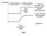
- the level of the cell-specific reference signal received by the base station user over the frequency band of the relay station will be significantly enhanced because the cell-specific reference signal of the base station and the cell-specific reference signal of the relay station overlap as illustrated in the curve 1 of Fig.3 . Therefore "a jump frequency point" of a channel parameter will be detected in the cell-specific reference signals at the edges of the frequency band of the base station and of the frequency band of the relay station and spread to a "jump frequency band" after two-dimension filtering as illustrated in the curve 2 of Fig.3 . Therefore both the base station user and the relay station user will be influenced while detecting data over the "jump frequency band".
- the relay user use the overlapping cell-specific reference signals for channel estimation and detection, and interference will not occur if the base station and the relay station are coordinated to transmit downlink data for the relay user or will occur if the base station transmits no coordinated data.
- interference will not be very significant because the user is close to the relay station and the power of the cell-specific reference signal of the base station is lower than that of the cell-specific reference signal of the relay station.
- the invention proposes a method for relay user selection and downlink resource allocation in a relay communication system.
- a method for relay user selection and downlink resource allocation in a base station of a relay communication system wherein the base station determines a relay user and performs downlink resource allocation according to a pattern of a cell-specific reference signal thereof and/or a reception demodulation scheme of a mobile terminal.
- a processing apparatus for relay user selection and downlink resource allocation in a base station of a relay communication system, wherein the processing apparatus determines a relay user and performs downlink resource allocation according to a pattern of a cell-specific reference signal thereof and/or a reception demodulation scheme of a mobile terminal.
- a base station for a relay communication system which includes the processing apparatus according to the second aspect of the invention.
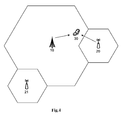
- Fig.4 illustrates a schematic diagram of a relay communication system according to an embodiment of the invention.
- the relay communication system includes a base station 10, a relay station 20, a relay station 21 and a mobile terminal 30.
- the relay stations 20 and 21 are located in a service area of the base station 10. Since the transmission power of a relay station is typically lower than that of a base station, service areas of both the relay stations 20 and 21 are smaller than that of the base station 10.
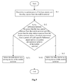
- Fig.5 illustrates a flow chart of a method, in a base station of a relay communication system, for selecting from the base station and a relay station thereof a serving device for a mobile terminal according to an embodiment of the invention. The embodiment will be described below based upon the base station 10, the relay station 20 and the mobile terminal 30 with reference to Fig.5 .
- the base station 10 will determine reception power thereof from the mobile terminal 30 and reception power of the relay station 20 from the mobile terminal 30, where the base station 10 acquires the reception power of the relay station 20 from the mobile terminal 30 by exchanging control information with the relay station 20.
- the base station 12 compares the difference between the power that it receives from the mobile terminal 30 and the power that the relay station 20 receives from the mobile terminal 30 with a threshold.
- the threshold here is determined from a pattern of a cell-specific reference signal of the base station 10 and/or a reception demodulation scheme of the mobile terminal 30.
- a relay user may be selected in view of the reception power of the base station 10 and the relay station 20 from the mobile terminal 30.
- the relay user is selected taking into no account the pattern of the cell-specific reference signal of the base station 10 and/or the reception demodulation scheme of the mobile terminal 30, particularly a channel detection scheme used based upon a cell-specific reference signal by the mobile terminal 30 during reception demodulation and possibly consequential interference due to the cell-specific reference signal transmitted from the base station 10 overlapping with a cell-specific reference signal transmitted from the relay station 20.
- the threshold in the step S12 includes a tolerance item determined from the pattern of the cell-specific reference signal of the base station 10 and/or the reception demodulation scheme of the mobile terminal 30.
- the tolerance item is related to the reception demodulation scheme of the mobile terminal 30, particularly to the channel detection scheme used based upon a cell-specific reference signal by the mobile terminal 30.
- the tolerance item can be introduced so that the service area of the relay station 20 is larger than that in the prior art, thereby reducing interference to a base station user close to the service area of the relay station due to the overlapping cell-specific reference signals.
- the base station 10 will select a serving device of the mobile terminal 30 according to the result of comparison in the step S12. Specifically in the sub-step S131, if the difference between the power that the base station 10 receives from the mobile terminal 30 and the power that the relay station 20 receives from the mobile terminal 30 is above the threshold, then the base station 10 is selected as a serving device of the mobile terminal 30; and in the sub-step S132, if the difference between the power that the base station 10 receives from the mobile terminal 30 and the power that the relay station 20 receives from the mobile terminal 30 is below or equal to the threshold, then the relay station 20 is selected as a serving device of the mobile terminal 30.
- the base station 10 will further perform the step of comparing power that a plurality of relay stations thereof receive from the mobile terminal 30 with each other and determine one of the relay stations that receives the highest power from the mobile terminal 30. Specifically, the base station 10 acquires the reception power of the relay station 20 from the mobile terminal 30 and reception power of the relay station 21 from the mobile terminal 30 by exchanging control information with the relay stations 20 and 21 and determines from comparison thereof that the reception power of the relay station 20 from the mobile terminal 30 is higher than the reception power of the relay station 21 from the mobile terminal 30. With the steps S11 to S13, the base station 10 will select a serving device of the mobile terminal 30 from the base station 10 and the one of the relay stations that receives the highest power from the mobile terminal 30.
- the present embodiment further includes such a step that the base station 10 will transmit a control instruction to the relay station 20 to instruct the relay station 20 to transmit the cell-specific reference signal in a downlink resource block thereof in the same pattern as the pattern of the cell-specific reference signal of the base station 10.
- the reception power of the base station 10 from the mobile terminal 30 is derived from downlink transmission power at which the base station 10 transmits a downlink signal to the mobile terminal 30, and the reception power of the relay station 20 from the mobile terminal 30 is derived from downlink transmission power at which the relay station 20 transmits a downlink signal to the mobile terminal 30.
- inversion derivation can be used in a TDD system because parameters, e.g., a channel response, a path loss, etc., in the uplink, can be considered the same as a channel response, a path loss, etc., in the downlink in the TDD system.
- Fig.6 illustrates a flow chart of a method for downlink resource allocation in a base station of a relay communication system according to an embodiment of the invention.
- Fig.7 illustrates a schematic diagram of a cell-specific reference signal in a downlink frequency band of a relay station according to an embodiment of the invention, where a white blank square box represents a resource unit of data, a square box with netted patterns represents a resource unit of a cell-specific reference signal, a square box with dotted patterns represents a blank resource unit, and a square box with vertical strips represents a resource unit of a relay station-specific reference signal.
- the embodiment will be described below based upon the base station 10 and the relay station 20 with reference to Fig.6 and Fig.7 .
- the base station 10 allocates a downlink frequency band to the base station 20 as illustrated in Fig.7 , for example.
- the base station 10 determines in the downlink frequency band of the base station 20 a guard frequency band from a pattern of a cell-specific reference signal of the base station 10 and/or a reception demodulation scheme of a mobile terminal in the cell.
- the guard frequency band is located at the edge of the downlink frequency band of the base station 20.
- the base station 10 instructs the relay station 20 to remove in the guard frequency band thereof the cell-specific reference signal of the base station 10 while forwarding a downlink signal.
- square boxes with dotted patterns and denoted with 2 in the guard frequency band of the relay station 20 represent white blank resource units originally used for transmission of a cell-specific reference signal, and the base station 10 will instruct the relay station 20 to remove patterns of cell-specific reference signals of these resource units while forwarding downlink data.
- the relay station 20 will not transmit any signal in these resource units denoted with 2 while forwarding downlink data in response to the instruction of the base station 10.
- a cell-specific reference signal used for channel detection in the reception demodulation scheme of the base station user includes cell-specific reference signals in the resource units denoted with 1, 2 and 3, then curves 1 and 2 in Fig.8 illustrate a channel parameter detected at the location of the cell-specific reference signal and the channel parameter subject to two-dimension filtering respectively, which show that the channel parameter derived by the base station user will still suffer somewhat from influence due to the overlapping cell-specific reference signals over a jump frequency band; and if the cell-specific reference signal used for channel detection in a reception demodulation scheme of the base station user includes the cell-specific reference signals in the resource units denoted with 1 and 2 but not the cell-specific reference signal in the resource unit denoted with 3, then the channel parameter derived by the base station user will
- the base station 10 will further determine a minimum guard bandwidth from the reception demodulation scheme used for the mobile terminal in the cell, and the bandwidth of the guard frequency band in the downlink frequency band of the relay station 20 will not be smaller than this minimum guard bandwidth.
- the minimum guard bandwidth is equal to the maximum frequency interval between a cell-specific reference signal used by a user for channel detection beyond a downlink resource block thereof and the downlink resource block thereof, for example.
- the base station 10 will further perform the step of instructing the relay station 20 to transmit a relay station-specific reference signal for downlink data demodulation of the relay station over the guard frequency band in a different pattern from the pattern of the cell-specific reference signal of the base station 10.
- the relay station 20 transmits, in the resource units denoted with vertical strips over the guard frequency band thereof, relay station-specific reference signals used by the mobile terminal for reception demodulation on data over the guard frequency band.
- the relay station 20 can alternatively transmit a relay station-specific reference signal over the entire downlink frequency band thereof in a different pattern from the pattern of the cell-specific reference signal of the base station 10.
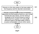
- Fig.9 illustrates a flow chart of a method for downlink resource allocation in a base station of a relay communication system according to an embodiment of the invention.
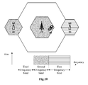
- Fig.10 illustrates a schematic diagram of downlink resource allocation according to an embodiment of the invention. The embodiment will be described below based upon the base station 10, the relay station 20, the relay station 21 and the mobile terminal 30 with reference to Fig.9 and Fig.10 .
- the base station 10 allocates to its first relay station, e.g., the relay station 20, a first frequency band for downlink transmission.
- a first frequency band for downlink transmission As illustrated in Fig.10 , for example, the first frequency band denoted with horizontal strips is allocated to the relay station 20 for downlink transmission.
- the base station 10 allocates a second frequency band immediately adjacent to the first frequency band to a user remote from the first relay station, and the minimum width of the second frequency band is determined from a pattern of a cell-specific reference signal of the base station 10 and/or a reception demodulation scheme of the mobile terminal in the cell.
- the second frequency band denoted with slanted strips is allocated to the user remote from the relay station 20.
- the minimum bandwidth of the second frequency band is equal to the maximum frequency interval between a cell-specific reference signal used for channel detection in a reception demodulation scheme of a user beyond a downlink resource block of the user and the downlink resource block thereof, for example.
- the user for which the second frequency band is used is remote from the relay station 20, so the user and a user served by the relay station 20 will suffer from little interference due to the overlapping cell-specific reference signals during reception demodulation. Also the minimum bandwidth of the second frequency band is determined from the reception demodulation scheme of the user in the cell so that a cell-specific reference signal used for channel detection of the user for which the first frequency band is used will not go beyond the first and second frequency bands.
- a third frequency band is immediately adjacent to the second frequency band on the other side opposite to the first frequency band, and no matter whichever user the third frequency band is allocated, a user for which the third frequency band is used and the user for which the first frequency band is used will not suffer from any interference due to their cell-specific reference signals overlapping with each other during reception demodulation.
- the user to which the second frequency band is allocated for use can be a base station user or a relay station user.
- the step S32 will particularly be performed differently dependent upon the different user to which the second frequency band is allocated for use.
- the base station 10 allocates the second frequency band directly to the relay station serving the user.
- the base station 10 allocates the second frequency band to the second relay station.
- the distance threshold here is for the purpose of ensuring sufficiently small influence of the cell-specific reference signal of the relay stations 20 and 21 upon the performance of reception demodulation of the user served by the other relay station.
- the base station 10 will further judge a condition of the user.
- the distance of a mobile terminal, e.g., the mobile terminal 30, to the base station 10 is below a distance threshold or power that the base station 10 receives from the mobile terminal is above a power threshold, then the base station 10 allocates the second frequency band to the mobile terminal.
- Both the distance threshold and the power threshold are for the purpose of ensuring sufficiently small influence of the cell-specific reference signal of the relay station 20 upon the performance of reception demodulation of the user to which the second frequency band is allocated. More particularly, both the distance threshold and the power threshold here are determined from the cell-specific reference signal of the base station 10 and/or the reception demodulation scheme of the mobile terminal 30.
- Fig.11 illustrates a structural block diagram of a processing apparatus in a base station of a relay communication system according to an embodiment of the invention.
- the processing apparatus 100 according to the embodiment includes first determination means 101, first comparison means 102 and selection means 103.
- the processing apparatus 100 is arranged in the base station 10. The embodiment will be described below based upon the base station 10, the relay station 20, the mobile terminal 30 and the processing apparatus 100 with reference to Fig.11 .
- the first determination means 101 in the processing apparatus 100 will determine reception power of the base station 10 from the mobile terminal 30 and reception power of the relay station 20 from the mobile terminal 30, where the first determination means 101 acquires the reception power of the relay station 20 from the mobile terminal 30 by exchanging control information with the relay station 20.
- the first comparison means 102 in the processing apparatus 100 compares the difference between the power that the base station 100 receives from the mobile terminal 30 and the power that the relay station 20 receives from the mobile terminal 30, both of which are determined by the first determination means 101, with a threshold.
- the threshold here is determined from a pattern of a cell-specific reference signal of the base station 10 and/or a reception demodulation scheme of the mobile terminal 30.
- a relay user may be selected in view of the reception power of the base station 10 and the relay station 20 from the mobile terminal 30.
- the relay user is selected taking into no account the pattern of the cell-specific reference signal of the base station 10 and/or the reception demodulation scheme of the mobile terminal 30, particularly a channel detection scheme used based upon a cell-specific reference signal by the mobile terminal 30 during reception demodulation and possibly consequential interference due to the cell-specific reference signal transmitted from the base station 10 overlapping with a cell-specific reference signal transmitted from the relay station 20.
- the threshold used in the first comparison means 102 includes a tolerance item determined from the pattern of the cell-specific reference signal of the base station 10 and/or the reception demodulation scheme of the mobile terminal 30.
- the tolerance item is related to the reception demodulation scheme of the mobile terminal 30, particularly to the channel detection scheme used based upon a cell-specific reference signal by the mobile terminal 30.
- the tolerance item can be introduced so that the service area of the relay station 20 is larger than that in the prior art, thereby reducing interference to a base station user close to the service area of the relay station due to the overlapping cell-specific reference signals.
- the selection means 103 in the processing apparatus 100 will select a serving device of the mobile terminal 30 according to the result of comparison of the first comparison means 102. Specifically, if the difference between the power that the base station 10 receives from the mobile terminal 30 and the power that the relay station 20 receives from the mobile terminal 30 is above the threshold, then the selection means 103 selects the base station 10 as a serving device of the mobile terminal 30; and if the difference between the power that the base station 10 receives from the mobile terminal 30 and the power that the relay station 20 receives from the mobile terminal 30 is below or equal to the threshold, then the selection means 103 selects the relay station 20 as a serving device of the mobile terminal 30.
- the processing apparatus 100 is further configured to compare power that a plurality of relay stations of the base station 10 receive from the mobile terminal 30 with each other and to determine one of the relay stations that receives the highest power from the mobile terminal 30.
- the first determination means 101 acquires the reception power of the relay station 20 from the mobile terminal 30 and reception power of the relay station 21 from the mobile terminal 30 by exchanging control information with the relay stations 20 and 21 and determines from comparison thereof that the reception power of the relay station 20 from the mobile terminal 30 is higher than the reception power of the relay station 21 from the mobile terminal 30.
- the processing apparatus 100 will select a serving device of the mobile terminal 30 from the base station 10 and the one of the relay stations that receives the highest power from the mobile terminal 30.
- the processing apparatus 100 further includes first instruction means configured to transmit a control instruction to the relay station 20 to instruct the relay station 20 to transmit the cell-specific reference signal in its downlink resource block in the same pattern as the pattern of the cell-specific reference signal of the base station 10.
- the first determination means 101 derives, the reception power of the base station 10 from the mobile terminal 30, from downlink transmission power at which the base station 10 transmits a downlink signal to the mobile terminal 30, and derives, the reception power of the relay station 20 from the mobile terminal 30, from downlink transmission power at which the relay station 200 transmits a downlink signal to the mobile terminal 30.
- inversion derivation can be used in a TDD system because parameters, e.g., a channel response, a path loss, etc., in the uplink, can be considered the same as a channel response, a path loss, etc., in the downlink in the TDD system.
- Fig.12 illustrates a structural block diagram of a processing apparatus in a base station of a relay communication system according to an embodiment of the invention.
- the processing apparatus 200 according to the embodiment includes first allocation means 201, second determination means 202 and second instruction means 203.
- the processing apparatus 200 is arranged in the base station 10. The embodiment will be described below based upon the base station 10, the relay station 20 and the processing apparatus 200 with reference to Fig.7 and Fig.11 .
- the first allocation means 201 in the processing apparatus 200 allocates a downlink frequency band to the base station 20 as illustrated in Fig.7 , for example.
- the second determination means 202 in the processing apparatus 200 determines in the downlink frequency band of the base station 20 a guard frequency band from a pattern of a cell-specific reference signal of the base station 10 and/or a reception demodulation scheme of a mobile terminal in the cell.
- the guard frequency band is located at the edge of the downlink frequency band of the base station 20.
- the second instruction means 203 in the processing apparatus 200 instructs the relay station 20 to remove in its guard frequency band the cell-specific reference signal of the base station 10 while forwarding a downlink signal.
- square boxes with dotted patterns and denoted with 2 in the guard frequency band of the relay station 20 represent white blank resource units originally used for transmission of a cell-specific reference signal, and the second instruction means 203 will instruct the relay station 20 to remove patterns of cell-specific reference signals of these resource units while forwarding downlink data.
- the relay station 20 will not transmit any signal in these resource units denoted with 2 while forwarding downlink data in response to the instruction of the second instruction means 203.
- a cell-specific reference signal used for channel detection in the reception demodulation scheme of the base station user includes cell-specific reference signals in the resource units denoted with 1, 2 and 3, then curves 1 and 2 in Fig.8 illustrate a channel parameter detected at the location of the cell-specific reference signal and the channel parameter subject to two-dimension filtering respectively, which show that the channel parameter derived by the base station user will still suffer somewhat from influence due to the overlapping cell-specific reference signals over a jump frequency band; and if the cell-specific reference signal used for channel detection in a reception demodulation scheme of the base station user includes the cell-specific reference signals in the resource units denoted with 1 and 2 but not the cell-specific reference signal in the resource unit denoted with 3, then the channel parameter derived by the base station user will
- the second determination means 202 is further configured to determine a minimum guard bandwidth from the reception demodulation scheme used for the mobile terminal in the cell, and the bandwidth of the guard frequency band in the downlink frequency band of the relay station 20 will not be smaller than this minimum guard bandwidth.
- the minimum guard bandwidth is equal to the maximum frequency interval between a cell-specific reference signal used by a user for channel detection beyond a downlink resource block thereof and the downlink resource block thereof, for example.
- the processing apparatus 200 further includes third instruction means configured to instruct the relay station 20 to transmit a relay station-specific reference signal for downlink data demodulation of the relay station over the guard frequency band in a different pattern from the pattern of the cell-specific reference signal of the base station 10.
- the relay station 20 transmits, in the resource units denoted with vertical strips over its guard frequency band, relay station-specific reference signals used by the mobile terminal for reception demodulation on data over the guard frequency band.
- the relay station 20 can alternatively transmit a relay station-specific reference signal over its entire downlink frequency band in a different pattern from the pattern of the cell-specific reference signal of the base station 10.
- Fig.13 illustrates a structural block diagram of a processing apparatus in a base station of a relay communication system according to an embodiment of the invention.
- the processing apparatus 300 according to the embodiment includes second allocation means 301 and third allocation means 302.
- the processing apparatus 300 is arranged in the base station 10. The embodiment will be described below based upon the base station 10, the relay station 20, the base station 21, the mobile terminal 30 and the processing apparatus 300 with reference to Fig.10 and Fig.13 .
- the second allocation means 301 in the processing apparatus 300 allocates to a first relay station, e.g., the relay station 20, of the base station 10 a first frequency band for downlink transmission.
- a first relay station e.g., the relay station 20
- the first frequency band denoted with horizontal strips is allocated to the relay station 20 for downlink transmission.
- the third allocation means 302 in the processing apparatus 300 allocates a second frequency band immediately adjacent to the first frequency band to a user remote from the first relay station, and the minimum width of the second frequency band is determined from a pattern of a cell-specific reference signal of the base station 10 and/or a reception demodulation scheme of the mobile terminal in the cell.
- the second frequency band denoted with slanted strips is allocated to the user remote from the relay station 20.
- the minimum bandwidth of the second frequency band is equal to the maximum frequency interval between a cell-specific reference signal used for channel detection in a reception demodulation scheme of a user beyond a downlink resource block of the user and the downlink resource block thereof, for example.
- the user for which the second frequency band is used is remote from the relay station 20, so the user and a user served by the relay station 20 will suffer from little interference due to the overlapping cell-specific reference signals during reception demodulation. Also the minimum bandwidth of the second frequency band is determined from the reception demodulation scheme of the user in the cell so that a cell-specific reference signal used for channel detection of the user for which the first frequency band is used will not go beyond the first and second frequency bands.
- a third frequency band is immediately adjacent to the second frequency band on the other side opposite to the first frequency band, and no matter whichever user the third frequency band is allocated, a user for which the third frequency band is used and the user for which the first frequency band is used will not suffer from any interference due to their cell-specific reference signals overlapping with each other during reception demodulation.
- the user to which the second frequency band is allocated for use can be a base station user or a relay station user.
- the third allocation means 302 also performs a specific operation dependent upon the different user to which the second frequency band is allocated for use.
- the third allocation means 302 allocates the second frequency band directly to the relay station serving the user.
- the third allocation means 302 will make judgment so that if the distance of a second relay station of the base station 10 to the first relay station is above a threshold, then the second frequency band is allocated to the second relay station. For example, the distance of the relay station 21 to the relay station 20 is above a threshold, and the third allocation means 302 allocates the second frequency band to the relay station 21.
- This threshold is for the purpose of ensuring sufficiently small influence of the cell-specific reference signals transmitted from the two relay stations upon the performance of reception demodulation of opposite users.
- the third allocation means 302 allocates the second frequency band directly to a relay station serving the user.
- the third allocation means 302 will further judge a condition of the user. If the distance of a mobile terminal, e.g., the mobile terminal 30, to the base station 10 is below a distance threshold or power that the base station 10 receives from the mobile terminal is above a power threshold, then the third allocation means 302 allocates the second frequency band to the mobile terminal.
- Both the distance threshold and the power threshold here are for the purpose of ensuring sufficiently small influence of the cell-specific reference signal of the relay station 20 upon the performance of reception demodulation of the user to which the second frequency band is allocated. More particularly, both the distance threshold and the power threshold here are determined from the cell-specific reference signal of the base station 10 and/or the reception demodulation scheme of the mobile terminal 30.
- the respective means as referred to in the invention can be implemented with hardware means, with functional modules in software or with hardware means integrated with functional modules in software.
- the respective means can be merged, decomposed and recombined according to mutual relationships between the functions performed by the respective means.
- the second allocation means 301 and the third allocation means 302 in the processing apparatus 300 can be combined into one means.
- selection of a relay user is decided by an evolved Node B, i.e., a base station, and therefore the method, apparatus and device according to the invention can be applicable particularly to the LTE-A specification.
- a relay base station or a mobile terminal can initiate on its own initiative execution of the user selection function or the downlink resource allocation function.
Landscapes
- Engineering & Computer Science (AREA)
- Signal Processing (AREA)
- Computer Networks & Wireless Communication (AREA)
- Computer Security & Cryptography (AREA)
- Mobile Radio Communication Systems (AREA)
- Radio Relay Systems (AREA)
Abstract
Description
- The present invention relates to a relay communication system and in particular to a technology of relay user selection and downlink resource allocation in a relay communication system.
- An existing LTE system uses a Cell-specific Reference Signal (CRS) for detection and demodulation of a downlink channel. As described in the 3GPP TS36.211 (v8.5.0) protocol, the cell-specific reference signal covers the entire bandwidth of a cell and is transmitted at the same power, and all the users served by the cell know the cell-specific reference signal of the cell. Therefore, the users generally can use the cell-specific reference signal as channel estimation.
- Generally a cell-specific reference signal used by a user for channel detection includes both a cell-specific reference signal in a resource block thereof and a cell-specific reference signal beyond the resource block thereof as a part of a reception demodulation scheme in order to improve the quality of data reception. As illustrated in
Fig.1 , a white blank square box represents a resource unit of data, a square box with netted patterns represents a resource unit of a cell-specific reference signal, a gray zone represents a resource block allocated to a user, and a square box denoted with 1 represents a resource unit of a cell-specific reference signal in the resource block, square boxes denoted with 2, 3 and 4 represent resource units of cell-specific reference signals adjacent to the resource block. For data demodulation, a set of cell-specific reference signals that can be used by the user for channel estimation includes signals of the resource units denoted with 1 and 2, signals of the resource units denoted with 1 and 3, signals of the resource units denoted with 1, 2 and 3, signals of the resource units denoted with 1, 2, 3 and 4, etc. A corresponding two-dimension filtering algorithm can be found in the article Robust Channel Estimation for OFDM Systems with Rapid Dispersive Fading Channels by Ye Li, L.J. Cimini, and N R. Sollenberger in IEEE Trans. Commun., vol. 46, No. 7, pp. 902-915, July 1998. However, channel estimation may suffer from an error when the resource unit of the cell-specific reference signal beyond the resource block is corrupted by a cell-specific reference signal transmitted from a relay station. - As specified in the latest relay protocol, a transparent relay will be included in the LTE-A specification, that is, the relay will transmit a cell-specific reference signal in the same resource unit as a base station. The relay station will transmit a cell-specific reference signal and a physical downlink control channel over the entire bandwidth for demodulation at a relay user.
- As described previously, a cell-specific reference signal used by a user for channel estimation typically includes a cell-specific reference signal in a resource block thereof and a cell-specific reference signal beyond the resource block thereof in order to improve the performance of channel estimation. As illustrated in
Fig.2 , a user of a base station receives both a cell-specific reference signal from the base station and a cell-specific reference signal from a relay station. When downlink frequency bands of the base station and the relay station are adjacent, a cell-specific reference signal used by the user to demodulate received data may include the cell-specific reference signal transmitted from the base station and the cell-specific reference signal transmitted from the relay station, both of which overlap with each other, thus degrading the performance of reception demodulation. - A general object of the invention is to address the foregoing problem present in the prior art.
- In the invention, a user served directly by a base station is referred to as a base station user, and a user served by a relay station is referred to as a relay user or a relay station user. A cell-specific reference signal transmitted from the base station is referred simply to as a cell-specific reference signal of the base station, and a cell-specific reference signal transmitted from the relay station is referred simply to as a cell-specific reference signal of the relay station.
- For a downlink shared physical channel, the base station will transmit the cell-specific reference signal over the entire frequency band, and there are a number of candidate schemes for a bandwidth occupied by the cell-specific reference signal transmitted from the relay station.
- There may be the following three scenarios for bandwidths occupied for the cell-specific reference signal and a data signal of the relay station which are transmitted at a single carrier frequency:
- In a first scenario, the data signal of the relay station occupies the entire bandwidth, and the cell-specific reference signal of the relay station also occupies the entire bandwidth;
- In a second scenario, the data signal of the relay station occupies a part of the bandwidth, and the cell-specific reference signal of the relay station occupies the entire bandwidth; and at this time the cell-specific reference signal of the relay station also occupies the entire bandwidths of the base station and the relay station overlap over the entire bandwidth so that the relay user can perform channel estimation over the entire bandwidth; and
- In a third scenario, both the data signal and the cell-specific reference signal of the relay station occupy only the part of the bandwidth allocated to the relay station.
- Also there may be the following three scenarios for bandwidths occupied for the cell-specific reference signal and the data signal of the relay station when being extended to transmission at multiple carrier frequencies:
- In a fourth scenario, the data signal of the relay station occupies the entire frequency band, and the cell-specific reference signal of the relay station also occupies the entire frequency band;
- In a fifth scenario, the data signal of the relay station occupies a part of the frequency band, and the cell-specific reference signal of the relay station occupies the entire frequency band; and
- In a sixth scenario, both the data signal and the cell-specific reference signal of the relay station occupy only the part of the frequency band allocated to the relay station.
- When the frequency bands/bandwidths occupied by the cell-specific reference signal and the data signal of the relay station satisfy the foregoing third and sixth scenarios, if the base station user is close to a service area of the relay station, the level of the cell-specific reference signal received by the base station user over the frequency band of the relay station will be significantly enhanced because the cell-specific reference signal of the base station and the cell-specific reference signal of the relay station overlap as illustrated in the
curve 1 ofFig.3 . Therefore "a jump frequency point" of a channel parameter will be detected in the cell-specific reference signals at the edges of the frequency band of the base station and of the frequency band of the relay station and spread to a "jump frequency band" after two-dimension filtering as illustrated in thecurve 2 ofFig.3 . Therefore both the base station user and the relay station user will be influenced while detecting data over the "jump frequency band". - When the frequency bands/bandwidths occupied by the cell-specific reference signal and the data signal of the relay station satisfy the foregoing second, fifth and sixth scenarios, a user close to the service area of the relay station will suffer from interference due to the cell-specific reference signal of the base station overlapping with the cell-specific reference signal of the relay station.
- For the relay user, the relay user use the overlapping cell-specific reference signals for channel estimation and detection, and interference will not occur if the base station and the relay station are coordinated to transmit downlink data for the relay user or will occur if the base station transmits no coordinated data. However interference will not be very significant because the user is close to the relay station and the power of the cell-specific reference signal of the base station is lower than that of the cell-specific reference signal of the relay station.
- For the base station user, the channel parameter derived by the base station user is h = h1 + h2, where h1 and h2 represent a parameter of a channel from the base station to the base station user and a parameter of a channel from the relay station to the base station user respectively. Data received by the base station user is y = h1s, where y and s represent a transmitted signal and a receive signal respectively. When the base station user is close to the service area of the relay station, h2 can not be neglected, and an unacceptable error will arise if the transmitted data s is recovered with h.
- In order to address the foregoing problems, the invention proposes a method for relay user selection and downlink resource allocation in a relay communication system.
- According to a first aspect of the invention, there is provided a method for relay user selection and downlink resource allocation in a base station of a relay communication system, wherein the base station determines a relay user and performs downlink resource allocation according to a pattern of a cell-specific reference signal thereof and/or a reception demodulation scheme of a mobile terminal.
- According to a second aspect of the invention, there is provided a processing apparatus for relay user selection and downlink resource allocation in a base station of a relay communication system, wherein the processing apparatus determines a relay user and performs downlink resource allocation according to a pattern of a cell-specific reference signal thereof and/or a reception demodulation scheme of a mobile terminal.
- According to a third aspect of the invention, there is provided a base station for a relay communication system, which includes the processing apparatus according to the second aspect of the invention.
- With the method, apparatus or device according to the invention, it is possible to alleviate and even eliminate influence of overlapping cell-specific reference signals upon the performance of reception demodulation at a user terminal.
- The other features, objects and advantages of the invention will become more apparent upon reading the following detailed description of non-limiting embodiments with reference to the drawings in which:
-
Fig.1 illustrates an illustrative pattern of a cell-specific reference signal for channel estimation; -
Fig.2 illustrates a schematic diagram of a mobile terminal receiving cell-specific reference signals from a base station and a relay station; -
Fig.3 illustrates a schematic diagram of a channel parameter derived by a mobile terminal jumping between a frequency band of a base station and a frequency band of a relay station; -
Fig.4 illustrates a schematic diagram of a relay communication system according to an embodiment of the invention; -
Fig.5 illustrates a flow chart of a method, in a base station of a relay communication system, for selecting from the base station and a relay station thereof a serving device for a mobile terminal according to an embodiment of the invention; -
Fig.6 illustrates a flow chart of a method for downlink resource allocation in a base station of a relay communication system according to an embodiment of the invention; -
Fig.7 illustrates a schematic diagram of a cell-specific reference signal in a downlink frequency band of a relay station according to an embodiment of the invention; -
Fig.8 illustrates a schematic diagram of a channel parameter derived by a mobile terminal jumping between the frequency band of a base station and a frequency band of a relay station according to an embodiment of the invention; -
Fig.9 illustrates a flow chart of a method for downlink resource allocation in a base station of a relay communication system according to an embodiment of the invention; -
Fig.10 illustrates a schematic diagram of downlink resource allocation according to an embodiment of the invention; -
Fig.11 illustrates a structural block diagram of a processing apparatus in a base station of a relay communication system according to an embodiment of the invention; -
Fig.12 illustrates a structural block diagram of a processing apparatus in a base station of a relay communication system according to an embodiment of the invention; and -
Fig.13 illustrates a structural block diagram of a processing apparatus in a base station of a relay communication system according to an embodiment of the invention. - Identical or like reference numerals will denote identical or like step features or means (modules).
-
Fig.4 illustrates a schematic diagram of a relay communication system according to an embodiment of the invention. As illustrated inFig.4 , the relay communication system according to the present embodiment includes abase station 10, arelay station 20, arelay station 21 and amobile terminal 30. Therelay stations base station 10. Since the transmission power of a relay station is typically lower than that of a base station, service areas of both therelay stations base station 10. - Respective illustrative embodiments of the invention will be described hereinafter with reference to
Fig.4 . -
Fig.5 illustrates a flow chart of a method, in a base station of a relay communication system, for selecting from the base station and a relay station thereof a serving device for a mobile terminal according to an embodiment of the invention. The embodiment will be described below based upon thebase station 10, therelay station 20 and themobile terminal 30 with reference toFig.5 . - Firstly in the step S11, the
base station 10 will determine reception power thereof from themobile terminal 30 and reception power of therelay station 20 from themobile terminal 30, where thebase station 10 acquires the reception power of therelay station 20 from themobile terminal 30 by exchanging control information with therelay station 20. - Then in the step S12, the base station 12 compares the difference between the power that it receives from the
mobile terminal 30 and the power that therelay station 20 receives from themobile terminal 30 with a threshold. The threshold here is determined from a pattern of a cell-specific reference signal of thebase station 10 and/or a reception demodulation scheme of themobile terminal 30. - In the prior art, a relay user may be selected in view of the reception power of the
base station 10 and therelay station 20 from themobile terminal 30. However in the prior art, the relay user is selected taking into no account the pattern of the cell-specific reference signal of thebase station 10 and/or the reception demodulation scheme of themobile terminal 30, particularly a channel detection scheme used based upon a cell-specific reference signal by themobile terminal 30 during reception demodulation and possibly consequential interference due to the cell-specific reference signal transmitted from thebase station 10 overlapping with a cell-specific reference signal transmitted from therelay station 20. - In view of the foregoing problem in the prior art, the threshold in the step S12 includes a tolerance item determined from the pattern of the cell-specific reference signal of the
base station 10 and/or the reception demodulation scheme of themobile terminal 30. The tolerance item is related to the reception demodulation scheme of themobile terminal 30, particularly to the channel detection scheme used based upon a cell-specific reference signal by themobile terminal 30. The tolerance item can be introduced so that the service area of therelay station 20 is larger than that in the prior art, thereby reducing interference to a base station user close to the service area of the relay station due to the overlapping cell-specific reference signals. - In the step S13, the
base station 10 will select a serving device of themobile terminal 30 according to the result of comparison in the step S12. Specifically in the sub-step S131, if the difference between the power that thebase station 10 receives from themobile terminal 30 and the power that therelay station 20 receives from themobile terminal 30 is above the threshold, then thebase station 10 is selected as a serving device of themobile terminal 30; and in the sub-step S132, if the difference between the power that thebase station 10 receives from themobile terminal 30 and the power that therelay station 20 receives from themobile terminal 30 is below or equal to the threshold, then therelay station 20 is selected as a serving device of themobile terminal 30. - According to a variation of the present embodiment, the
base station 10 will further perform the step of comparing power that a plurality of relay stations thereof receive from themobile terminal 30 with each other and determine one of the relay stations that receives the highest power from themobile terminal 30. Specifically, thebase station 10 acquires the reception power of therelay station 20 from themobile terminal 30 and reception power of therelay station 21 from themobile terminal 30 by exchanging control information with therelay stations relay station 20 from themobile terminal 30 is higher than the reception power of therelay station 21 from themobile terminal 30. With the steps S11 to S13, thebase station 10 will select a serving device of the mobile terminal 30 from thebase station 10 and the one of the relay stations that receives the highest power from themobile terminal 30. - Some relay stations only amplify and forward a received signal. Other relay stations will demodulate, modulate again and forward a received signal. Therefore preferably the present embodiment further includes such a step that the
base station 10 will transmit a control instruction to therelay station 20 to instruct therelay station 20 to transmit the cell-specific reference signal in a downlink resource block thereof in the same pattern as the pattern of the cell-specific reference signal of thebase station 10. - Optionally in the step S11, the reception power of the
base station 10 from themobile terminal 30 is derived from downlink transmission power at which thebase station 10 transmits a downlink signal to themobile terminal 30, and the reception power of therelay station 20 from themobile terminal 30 is derived from downlink transmission power at which therelay station 20 transmits a downlink signal to themobile terminal 30. Typically such inversion derivation can be used in a TDD system because parameters, e.g., a channel response, a path loss, etc., in the uplink, can be considered the same as a channel response, a path loss, etc., in the downlink in the TDD system. -
Fig.6 illustrates a flow chart of a method for downlink resource allocation in a base station of a relay communication system according to an embodiment of the invention.Fig.7 illustrates a schematic diagram of a cell-specific reference signal in a downlink frequency band of a relay station according to an embodiment of the invention, where a white blank square box represents a resource unit of data, a square box with netted patterns represents a resource unit of a cell-specific reference signal, a square box with dotted patterns represents a blank resource unit, and a square box with vertical strips represents a resource unit of a relay station-specific reference signal. The embodiment will be described below based upon thebase station 10 and therelay station 20 with reference toFig.6 andFig.7 . - Firstly in the step S21, the
base station 10 allocates a downlink frequency band to thebase station 20 as illustrated inFig.7 , for example. - In the step S22, the
base station 10 determines in the downlink frequency band of the base station 20 a guard frequency band from a pattern of a cell-specific reference signal of thebase station 10 and/or a reception demodulation scheme of a mobile terminal in the cell. As illustrated inFig.7 , for example, the guard frequency band is located at the edge of the downlink frequency band of thebase station 20. - In the step S23, the
base station 10 instructs therelay station 20 to remove in the guard frequency band thereof the cell-specific reference signal of thebase station 10 while forwarding a downlink signal. As illustrated inFig.7 , for example, square boxes with dotted patterns and denoted with 2 in the guard frequency band of therelay station 20 represent white blank resource units originally used for transmission of a cell-specific reference signal, and thebase station 10 will instruct therelay station 20 to remove patterns of cell-specific reference signals of these resource units while forwarding downlink data. Therelay station 20 will not transmit any signal in these resource units denoted with 2 while forwarding downlink data in response to the instruction of thebase station 10. - With an application of the method according to the present embodiment, for a base station user with a downlink frequency band located in the frequency band of the base station illustrated in
Fig.7 , when therelay station 20 transmits the cell-specific reference signal only over the downlink frequency band, if a cell-specific reference signal used for channel detection in the reception demodulation scheme of the base station user includes cell-specific reference signals in the resource units denoted with 1, 2 and 3, then curves 1 and 2 inFig.8 illustrate a channel parameter detected at the location of the cell-specific reference signal and the channel parameter subject to two-dimension filtering respectively, which show that the channel parameter derived by the base station user will still suffer somewhat from influence due to the overlapping cell-specific reference signals over a jump frequency band; and if the cell-specific reference signal used for channel detection in a reception demodulation scheme of the base station user includes the cell-specific reference signals in the resource units denoted with 1 and 2 but not the cell-specific reference signal in the resource unit denoted with 3, then the channel parameter derived by the base station user will not suffer from any influence due to the overlapping cell-specific reference signals. Therefore optionally in the step S22, thebase station 10 will further determine a minimum guard bandwidth from the reception demodulation scheme used for the mobile terminal in the cell, and the bandwidth of the guard frequency band in the downlink frequency band of therelay station 20 will not be smaller than this minimum guard bandwidth. Specifically, the minimum guard bandwidth is equal to the maximum frequency interval between a cell-specific reference signal used by a user for channel detection beyond a downlink resource block thereof and the downlink resource block thereof, for example. - Optionally following the step S22, the
base station 10 will further perform the step of instructing therelay station 20 to transmit a relay station-specific reference signal for downlink data demodulation of the relay station over the guard frequency band in a different pattern from the pattern of the cell-specific reference signal of thebase station 10. As illustrated inFig.7 , for example, therelay station 20 transmits, in the resource units denoted with vertical strips over the guard frequency band thereof, relay station-specific reference signals used by the mobile terminal for reception demodulation on data over the guard frequency band. Those skilled in the art shall appreciate that therelay station 20 can alternatively transmit a relay station-specific reference signal over the entire downlink frequency band thereof in a different pattern from the pattern of the cell-specific reference signal of thebase station 10. -
Fig.9 illustrates a flow chart of a method for downlink resource allocation in a base station of a relay communication system according to an embodiment of the invention.Fig.10 illustrates a schematic diagram of downlink resource allocation according to an embodiment of the invention. The embodiment will be described below based upon thebase station 10, therelay station 20, therelay station 21 and themobile terminal 30 with reference toFig.9 andFig.10 . - Firstly in the step S31, the
base station 10 allocates to its first relay station, e.g., therelay station 20, a first frequency band for downlink transmission. As illustrated inFig.10 , for example, the first frequency band denoted with horizontal strips is allocated to therelay station 20 for downlink transmission. - In the step S32, the
base station 10 allocates a second frequency band immediately adjacent to the first frequency band to a user remote from the first relay station, and the minimum width of the second frequency band is determined from a pattern of a cell-specific reference signal of thebase station 10 and/or a reception demodulation scheme of the mobile terminal in the cell. As illustrated inFig.10 , for example, the second frequency band denoted with slanted strips is allocated to the user remote from therelay station 20. Specifically, the minimum bandwidth of the second frequency band is equal to the maximum frequency interval between a cell-specific reference signal used for channel detection in a reception demodulation scheme of a user beyond a downlink resource block of the user and the downlink resource block thereof, for example. - When the respective relay stations transmit cell-specific reference signals only over their respective downlink frequency bands, the user for which the second frequency band is used is remote from the
relay station 20, so the user and a user served by therelay station 20 will suffer from little interference due to the overlapping cell-specific reference signals during reception demodulation. Also the minimum bandwidth of the second frequency band is determined from the reception demodulation scheme of the user in the cell so that a cell-specific reference signal used for channel detection of the user for which the first frequency band is used will not go beyond the first and second frequency bands. As illustrated inFig.10 , for example, a third frequency band is immediately adjacent to the second frequency band on the other side opposite to the first frequency band, and no matter whichever user the third frequency band is allocated, a user for which the third frequency band is used and the user for which the first frequency band is used will not suffer from any interference due to their cell-specific reference signals overlapping with each other during reception demodulation. - The user to which the second frequency band is allocated for use can be a base station user or a relay station user. The step S32 will particularly be performed differently dependent upon the different user to which the second frequency band is allocated for use.
- If the user to which the second frequency band is allocated for use is a relay station user, then the
base station 10 allocates the second frequency band directly to the relay station serving the user. In the step S32, if the distance of a second relay station to a first relay station of thebase station 10 is below a distance threshold, then thebase station 10 allocates the second frequency band to the second relay station. For example, the distance of therelay station 21 to therelay station 20 is above a threshold, thebase station 10 allocates the second frequency band to therelay station 21. The distance threshold here is for the purpose of ensuring sufficiently small influence of the cell-specific reference signal of therelay stations - If the user to which the second frequency band is allocated for use is a base station user, then the
base station 10 will further judge a condition of the user. In the step S32, if the distance of a mobile terminal, e.g., themobile terminal 30, to thebase station 10 is below a distance threshold or power that thebase station 10 receives from the mobile terminal is above a power threshold, then thebase station 10 allocates the second frequency band to the mobile terminal. Both the distance threshold and the power threshold here are for the purpose of ensuring sufficiently small influence of the cell-specific reference signal of therelay station 20 upon the performance of reception demodulation of the user to which the second frequency band is allocated. More particularly, both the distance threshold and the power threshold here are determined from the cell-specific reference signal of thebase station 10 and/or the reception demodulation scheme of themobile terminal 30. -
Fig.11 illustrates a structural block diagram of a processing apparatus in a base station of a relay communication system according to an embodiment of the invention. As illustrated inFig.11 , the processing apparatus 100 according to the embodiment includes first determination means 101, first comparison means 102 and selection means 103. Typically the processing apparatus 100 is arranged in thebase station 10. The embodiment will be described below based upon thebase station 10, therelay station 20, themobile terminal 30 and the processing apparatus 100 with reference toFig.11 . - Firstly the first determination means 101 in the processing apparatus 100 will determine reception power of the
base station 10 from themobile terminal 30 and reception power of therelay station 20 from themobile terminal 30, where the first determination means 101 acquires the reception power of therelay station 20 from themobile terminal 30 by exchanging control information with therelay station 20. - Then the first comparison means 102 in the processing apparatus 100 compares the difference between the power that the base station 100 receives from the
mobile terminal 30 and the power that therelay station 20 receives from themobile terminal 30, both of which are determined by the first determination means 101, with a threshold. The threshold here is determined from a pattern of a cell-specific reference signal of thebase station 10 and/or a reception demodulation scheme of themobile terminal 30. - In the prior art, a relay user may be selected in view of the reception power of the
base station 10 and therelay station 20 from themobile terminal 30. However in the prior art, the relay user is selected taking into no account the pattern of the cell-specific reference signal of thebase station 10 and/or the reception demodulation scheme of themobile terminal 30, particularly a channel detection scheme used based upon a cell-specific reference signal by themobile terminal 30 during reception demodulation and possibly consequential interference due to the cell-specific reference signal transmitted from thebase station 10 overlapping with a cell-specific reference signal transmitted from therelay station 20. - In view of the foregoing problem in the prior art, the threshold used in the first comparison means 102 includes a tolerance item determined from the pattern of the cell-specific reference signal of the
base station 10 and/or the reception demodulation scheme of themobile terminal 30. The tolerance item is related to the reception demodulation scheme of themobile terminal 30, particularly to the channel detection scheme used based upon a cell-specific reference signal by themobile terminal 30. The tolerance item can be introduced so that the service area of therelay station 20 is larger than that in the prior art, thereby reducing interference to a base station user close to the service area of the relay station due to the overlapping cell-specific reference signals. - Next, the selection means 103 in the processing apparatus 100 will select a serving device of the
mobile terminal 30 according to the result of comparison of the first comparison means 102. Specifically, if the difference between the power that thebase station 10 receives from themobile terminal 30 and the power that therelay station 20 receives from themobile terminal 30 is above the threshold, then the selection means 103 selects thebase station 10 as a serving device of themobile terminal 30; and if the difference between the power that thebase station 10 receives from themobile terminal 30 and the power that therelay station 20 receives from themobile terminal 30 is below or equal to the threshold, then the selection means 103 selects therelay station 20 as a serving device of themobile terminal 30. - According to a variation of the present embodiment, the processing apparatus 100 is further configured to compare power that a plurality of relay stations of the
base station 10 receive from themobile terminal 30 with each other and to determine one of the relay stations that receives the highest power from themobile terminal 30. Specifically, the first determination means 101 acquires the reception power of therelay station 20 from themobile terminal 30 and reception power of therelay station 21 from themobile terminal 30 by exchanging control information with therelay stations relay station 20 from themobile terminal 30 is higher than the reception power of therelay station 21 from themobile terminal 30. With the operations performed by the first determination means 101, the first comparison means 102 and the selection means 103, the processing apparatus 100 will select a serving device of the mobile terminal 30 from thebase station 10 and the one of the relay stations that receives the highest power from themobile terminal 30. - Some relay stations only amplify and forward a received signal. Other relay stations will demodulate, modulate again and forward a received signal. Therefore preferably the processing apparatus 100 according to the present embodiment further includes first instruction means configured to transmit a control instruction to the
relay station 20 to instruct therelay station 20 to transmit the cell-specific reference signal in its downlink resource block in the same pattern as the pattern of the cell-specific reference signal of thebase station 10. - Optionally, the first determination means 101 derives, the reception power of the
base station 10 from themobile terminal 30, from downlink transmission power at which thebase station 10 transmits a downlink signal to themobile terminal 30, and derives, the reception power of therelay station 20 from themobile terminal 30, from downlink transmission power at which therelay station 200 transmits a downlink signal to themobile terminal 30. Typically such inversion derivation can be used in a TDD system because parameters, e.g., a channel response, a path loss, etc., in the uplink, can be considered the same as a channel response, a path loss, etc., in the downlink in the TDD system. -
Fig.12 illustrates a structural block diagram of a processing apparatus in a base station of a relay communication system according to an embodiment of the invention. As illustrated in Fig.l2, theprocessing apparatus 200 according to the embodiment includes first allocation means 201, second determination means 202 and second instruction means 203. Typically theprocessing apparatus 200 is arranged in thebase station 10. The embodiment will be described below based upon thebase station 10, therelay station 20 and theprocessing apparatus 200 with reference toFig.7 andFig.11 . - Firstly, the first allocation means 201 in the
processing apparatus 200 allocates a downlink frequency band to thebase station 20 as illustrated inFig.7 , for example. - Then, the second determination means 202 in the
processing apparatus 200 determines in the downlink frequency band of the base station 20 a guard frequency band from a pattern of a cell-specific reference signal of thebase station 10 and/or a reception demodulation scheme of a mobile terminal in the cell. As illustrated inFig.7 , for example, the guard frequency band is located at the edge of the downlink frequency band of thebase station 20. - Next, the second instruction means 203 in the
processing apparatus 200 instructs therelay station 20 to remove in its guard frequency band the cell-specific reference signal of thebase station 10 while forwarding a downlink signal. As illustrated inFig.7 , for example, square boxes with dotted patterns and denoted with 2 in the guard frequency band of therelay station 20 represent white blank resource units originally used for transmission of a cell-specific reference signal, and the second instruction means 203 will instruct therelay station 20 to remove patterns of cell-specific reference signals of these resource units while forwarding downlink data. Therelay station 20 will not transmit any signal in these resource units denoted with 2 while forwarding downlink data in response to the instruction of the second instruction means 203. - With an application of the device according to the present embodiment, for a base station user with a downlink frequency band located in the frequency band of the base station illustrated in
Fig.7 , when therelay station 20 transmits the cell-specific reference signal only over its downlink frequency band, if a cell-specific reference signal used for channel detection in the reception demodulation scheme of the base station user includes cell-specific reference signals in the resource units denoted with 1, 2 and 3, then curves 1 and 2 inFig.8 illustrate a channel parameter detected at the location of the cell-specific reference signal and the channel parameter subject to two-dimension filtering respectively, which show that the channel parameter derived by the base station user will still suffer somewhat from influence due to the overlapping cell-specific reference signals over a jump frequency band; and if the cell-specific reference signal used for channel detection in a reception demodulation scheme of the base station user includes the cell-specific reference signals in the resource units denoted with 1 and 2 but not the cell-specific reference signal in the resource unit denoted with 3, then the channel parameter derived by the base station user will not suffer from any influence due to the overlapping cell-specific reference signals. Therefore optionally, the second determination means 202 is further configured to determine a minimum guard bandwidth from the reception demodulation scheme used for the mobile terminal in the cell, and the bandwidth of the guard frequency band in the downlink frequency band of therelay station 20 will not be smaller than this minimum guard bandwidth. Specifically, the minimum guard bandwidth is equal to the maximum frequency interval between a cell-specific reference signal used by a user for channel detection beyond a downlink resource block thereof and the downlink resource block thereof, for example. - Optionally, the
processing apparatus 200 further includes third instruction means configured to instruct therelay station 20 to transmit a relay station-specific reference signal for downlink data demodulation of the relay station over the guard frequency band in a different pattern from the pattern of the cell-specific reference signal of thebase station 10. As illustrated inFig.7 , for example, therelay station 20 transmits, in the resource units denoted with vertical strips over its guard frequency band, relay station-specific reference signals used by the mobile terminal for reception demodulation on data over the guard frequency band. Those skilled in the art shall appreciate that therelay station 20 can alternatively transmit a relay station-specific reference signal over its entire downlink frequency band in a different pattern from the pattern of the cell-specific reference signal of thebase station 10. -
Fig.13 illustrates a structural block diagram of a processing apparatus in a base station of a relay communication system according to an embodiment of the invention. As illustrated in Fib.13, theprocessing apparatus 300 according to the embodiment includes second allocation means 301 and third allocation means 302. Typically theprocessing apparatus 300 is arranged in thebase station 10. The embodiment will be described below based upon thebase station 10, therelay station 20, thebase station 21, themobile terminal 30 and theprocessing apparatus 300 with reference toFig.10 andFig.13 . - Firstly the second allocation means 301 in the
processing apparatus 300 allocates to a first relay station, e.g., therelay station 20, of the base station 10 a first frequency band for downlink transmission. As illustrated inFig.10 , for example, the first frequency band denoted with horizontal strips is allocated to therelay station 20 for downlink transmission. - Then the third allocation means 302 in the
processing apparatus 300 allocates a second frequency band immediately adjacent to the first frequency band to a user remote from the first relay station, and the minimum width of the second frequency band is determined from a pattern of a cell-specific reference signal of thebase station 10 and/or a reception demodulation scheme of the mobile terminal in the cell. As illustrated inFig.10 , for example, the second frequency band denoted with slanted strips is allocated to the user remote from therelay station 20. Specifically, the minimum bandwidth of the second frequency band is equal to the maximum frequency interval between a cell-specific reference signal used for channel detection in a reception demodulation scheme of a user beyond a downlink resource block of the user and the downlink resource block thereof, for example. - When the respective relay stations transmit cell-specific reference signals only over their respective downlink frequency bands, the user for which the second frequency band is used is remote from the
relay station 20, so the user and a user served by therelay station 20 will suffer from little interference due to the overlapping cell-specific reference signals during reception demodulation. Also the minimum bandwidth of the second frequency band is determined from the reception demodulation scheme of the user in the cell so that a cell-specific reference signal used for channel detection of the user for which the first frequency band is used will not go beyond the first and second frequency bands. As illustrated inFig.10 , for example, a third frequency band is immediately adjacent to the second frequency band on the other side opposite to the first frequency band, and no matter whichever user the third frequency band is allocated, a user for which the third frequency band is used and the user for which the first frequency band is used will not suffer from any interference due to their cell-specific reference signals overlapping with each other during reception demodulation. - The user to which the second frequency band is allocated for use can be a base station user or a relay station user. The third allocation means 302 also performs a specific operation dependent upon the different user to which the second frequency band is allocated for use.
- If the user to which the second frequency band is allocated for use is a relay station user, then the third allocation means 302 allocates the second frequency band directly to the relay station serving the user. The third allocation means 302 will make judgment so that if the distance of a second relay station of the
base station 10 to the first relay station is above a threshold, then the second frequency band is allocated to the second relay station. For example, the distance of therelay station 21 to therelay station 20 is above a threshold, and the third allocation means 302 allocates the second frequency band to therelay station 21. This threshold is for the purpose of ensuring sufficiently small influence of the cell-specific reference signals transmitted from the two relay stations upon the performance of reception demodulation of opposite users. - If the user to which the second frequency band is allocated for use is a base station user, then the third allocation means 302 allocates the second frequency band directly to a relay station serving the user. The third allocation means 302 will further judge a condition of the user. If the distance of a mobile terminal, e.g., the
mobile terminal 30, to thebase station 10 is below a distance threshold or power that thebase station 10 receives from the mobile terminal is above a power threshold, then the third allocation means 302 allocates the second frequency band to the mobile terminal. Both the distance threshold and the power threshold here are for the purpose of ensuring sufficiently small influence of the cell-specific reference signal of therelay station 20 upon the performance of reception demodulation of the user to which the second frequency band is allocated. More particularly, both the distance threshold and the power threshold here are determined from the cell-specific reference signal of thebase station 10 and/or the reception demodulation scheme of themobile terminal 30. - Those skilled in the art shall appreciate that the respective means as referred to in the invention can be implemented with hardware means, with functional modules in software or with hardware means integrated with functional modules in software. The respective means can be merged, decomposed and recombined according to mutual relationships between the functions performed by the respective means. For example, the second allocation means 301 and the third allocation means 302 in the
processing apparatus 300 can be combined into one means. - According to the LTE-A specification, selection of a relay user is decided by an evolved Node B, i.e., a base station, and therefore the method, apparatus and device according to the invention can be applicable particularly to the LTE-A specification. Of course, those skilled in the art shall appreciate that a relay base station or a mobile terminal can initiate on its own initiative execution of the user selection function or the downlink resource allocation function.
- The foregoing description is merely illustrative of the non-limiting embodiments of the invention, but the invention will not be limited to any specific system, device or protocol, and those skilled in the art can make various variations or modifications without departing from the scope of the invention as defined in the appended claims.
Claims (23)
- A method for relay user selection and downlink resource allocation in a base station of a relay communication system, wherein the base station determines a relay user and performs downlink resource allocation according to a pattern of a cell-specific reference signal thereof and/or a reception demodulation scheme of a mobile terminal.
- The method according to claim 1, wherein when the base station selects a serving device for a mobile terminal from the base station and a relay station thereof, the method comprises the steps of:determining reception power of the base station and the relay station from the mobile terminal;comparing the difference between the power that the base station receives from the mobile terminal and the power that the relay station receives from the mobile terminal with a threshold determined from the pattern of the cell-specific reference signal of the base station and/or the reception demodulation scheme of the mobile terminal; andif the difference is above the threshold, then selecting the base station as a serving device of the mobile terminal; otherwise, selecting the relay station as a serving device of the mobile terminal.
- The method according to claim 2, further comprising the step of:instructing the relay station to transmit a cell-specific reference signal in a downlink resource block thereof in the same pattern as the pattern of the cell-specific reference signal of the base station.
- The method according to claim 2, wherein the power that the relay station receives from the mobile terminal is higher than reception power that other relay stations of the base station receive from the mobile terminal.
- The method according to any one of claims 2 to 4, wherein in the determination step, the power that the base station receives from the mobile terminal and the power that the relay station receives from the mobile terminal is determined from downlink transmission power that the mobile terminal receives from the base station and downlink transmission power that the mobile terminal receives from the relay station.
- The method according to claim 1, wherein when the base station performs downlink resource allocation, the method comprises the steps of:allocating a downlink frequency band to a relay station;determining in the downlink frequency band of the relay station a guard frequency band from the pattern of the cell-specific reference signal and/or the reception demodulation scheme of the mobile terminal; andinstructing the relay station to remove the cell-specific reference signal of the base station in the guard frequency band while forwarding a downlink signal.
- The method according to claim 6, further comprising: after the determination step,
instructing the relay station to transmit a relay station-specific reference signal for downlink data demodulation of the relay station over the guard frequency band in a different pattern from the pattern of the cell-specific reference signal of the base station. - The method according to claim 6 or 7, wherein the determination step comprises:determining a minimum guard bandwidth from the reception demodulation scheme of the mobile terminal, and the bandwidth of the guard frequency band is not smaller than the minimum guard bandwidth.
- The method according to claim 1, wherein when the base station performs downlink resource allocation, the method comprises the steps of:A. allocating to a first relay station of the base station a first frequency band for downlink transmission; andB. allocating a second frequency band immediately adjacent to the first frequency band to a user remote from the first relay station, and the minimum width of the second frequency band is determined from the pattern of the cell-specific reference signal of the base station and/or the reception demodulation pattern of the mobile terminal.
- The method according to claim 9, wherein the step B comprises:if the distance of a second relay station of the base station to the first relay station is above a threshold, then allocating the second frequency band to the second relay station.
- The method according to claim 9, wherein the step B comprises:if the distance of a mobile terminal to the base station is below a threshold or power that the base station receives from the mobile terminal is above a threshold, then allocating the second frequency band to the mobile terminal.
- A processing apparatus for relay user selection and downlink resource allocation in a base station of a relay communication system, wherein the processing apparatus determines a relay user and performs downlink resource allocation according to a pattern of a cell-specific reference signal thereof and/or a reception demodulation scheme of a mobile terminal.
- The processing apparatus according to claim 12, wherein when the processing apparatus selects a serving device for a mobile terminal from the base station and a relay station thereof, the processing apparatus comprises:first determination means configured to determine reception power of the base station and the relay station from the mobile terminal;first comparison means configured to compare the difference between the power that the base station receives from the mobile terminal and the power that the relay station receives from the mobile terminal with a threshold determined from the pattern of the cell-specific reference signal of the base station and/or the reception demodulation scheme of the mobile terminal; andselection means configured to, if the difference is above the threshold, then select the base station as a serving device of the mobile terminal; otherwise, select the relay station as a serving device of the mobile terminal.
- The processing apparatus according to claim 13, further comprising:first instruction means configured to instruct the relay station to transmit a cell-specific reference signal in a downlink resource block thereof in the same pattern as the pattern of the cell-specific reference signal of the base station.
- The processing apparatus according to claim 13, wherein the power that the relay station receives from the mobile terminal is higher than reception power that other relay stations of the base station receive from the mobile terminal.
- The processing apparatus according to any one of claims 13 to 15, wherein the first determination means determines, the power that the base station receives from the mobile terminal and the power that the relay station receives from the mobile terminal, from downlink transmission power that the mobile terminal receives from the base station and downlink transmission power that the mobile terminal receives from the relay station.
- The processing apparatus according to claim 12, wherein when the base station performs downlink resource allocation, the processing apparatus comprises:first allocation means configured to allocate a downlink frequency band to a relay station;second determination means configured to determine in the downlink frequency band of the relay station a guard frequency band from the pattern of the cell-specific reference signal and/or the reception demodulation scheme of the mobile terminal; andsecond instruction means configured to instruct the relay station to remove the cell-specific reference signal of the base station in the guard frequency band while forwarding a downlink signal.
- The processing apparatus according to claim 17, further comprising:third instruction means configured to instruct the relay station to transmit a relay station-specific reference signal for downlink data demodulation of the relay station over the guard frequency band in a different pattern from the pattern of the cell-specific reference signal of the base station.
- The processing apparatus according to claim 17 or 18, wherein the second determination means is further configured to determine a minimum guard bandwidth from the reception demodulation scheme of the mobile terminal, and the bandwidth of the guard frequency band is not smaller than the minimum guard bandwidth.
- The processing apparatus according to claim 12, wherein when the base station performs downlink resource allocation, the processing apparatus comprises:second allocation means configured to allocate to a first relay station of the base station a first frequency band for downlink transmission; andthird allocation means configured to allocate a second frequency band immediately adjacent to the first frequency band to a user remote from the first relay station, and the minimum width of the second frequency band is determined from the pattern of the cell-specific reference signal of the base station and/or the reception demodulation pattern of the mobile terminal.
- The processing apparatus according to claim 20, wherein the third allocation means is further configured to, if the distance of a second relay station of the base station to the first relay station is above a threshold, then allocate the second frequency band to the second relay station.
- The processing apparatus according to claim 20, wherein the third allocation means is further configured to, if the distance of a mobile terminal to the base station is below a threshold or power that the base station receives from the mobile terminal is above a threshold, then allocate the second frequency band to the mobile terminal.
- A base station for a relay communication system, comprising the processing apparatus according to any one of claims 12 to 22.
Applications Claiming Priority (1)
| Application Number | Priority Date | Filing Date | Title |
|---|---|---|---|
| PCT/CN2009/000409 WO2010118558A1 (en) | 2009-04-17 | 2009-04-17 | Method, apparatus and device for selecting relay user and allocating downlink resource |
Publications (2)
| Publication Number | Publication Date |
|---|---|
| EP2421307A1 true EP2421307A1 (en) | 2012-02-22 |
| EP2421307A4 EP2421307A4 (en) | 2014-11-12 |
Family
ID=42982107
Family Applications (1)
| Application Number | Title | Priority Date | Filing Date |
|---|---|---|---|
| EP09843192.7A Withdrawn EP2421307A4 (en) | 2009-04-17 | 2009-04-17 | Method, apparatus and device for selecting relay user and allocating downlink resource |
Country Status (7)
| Country | Link |
|---|---|
| US (1) | US9094093B2 (en) |
| EP (1) | EP2421307A4 (en) |
| JP (1) | JP5814225B2 (en) |
| KR (1) | KR101274458B1 (en) |
| CN (1) | CN102301797B (en) |
| BR (1) | BRPI0925013B1 (en) |
| WO (1) | WO2010118558A1 (en) |
Cited By (10)
| Publication number | Priority date | Publication date | Assignee | Title |
|---|---|---|---|---|
| WO2017214228A1 (en) * | 2016-06-10 | 2017-12-14 | At&T Intellectual Property I, L.P. | Method and apparatus for use with a radio distributed antenna system having an in-band reference signal |
| WO2017214229A1 (en) * | 2016-06-10 | 2017-12-14 | At&T Intellectual Property I, L.P. | Method and apparatus for use with a radio distributed antenna system having a clock reference |
| US9912027B2 (en) | 2015-07-23 | 2018-03-06 | At&T Intellectual Property I, L.P. | Method and apparatus for exchanging communication signals |
| US9973242B2 (en) | 2015-09-16 | 2018-05-15 | At&T Intellectual Property I, L.P. | Method and apparatus for use with a radio distributed antenna system |
| US10009063B2 (en) | 2015-09-16 | 2018-06-26 | At&T Intellectual Property I, L.P. | Method and apparatus for use with a radio distributed antenna system having an out-of-band reference signal |
| US10009901B2 (en) | 2015-09-16 | 2018-06-26 | At&T Intellectual Property I, L.P. | Method, apparatus, and computer-readable storage medium for managing utilization of wireless resources between base stations |
| US10051629B2 (en) | 2015-09-16 | 2018-08-14 | At&T Intellectual Property I, L.P. | Method and apparatus for use with a radio distributed antenna system having an in-band reference signal |
| US10079661B2 (en) | 2015-09-16 | 2018-09-18 | At&T Intellectual Property I, L.P. | Method and apparatus for use with a radio distributed antenna system having a clock reference |
| US10136434B2 (en) | 2015-09-16 | 2018-11-20 | At&T Intellectual Property I, L.P. | Method and apparatus for use with a radio distributed antenna system having an ultra-wideband control channel |
| US10811767B2 (en) | 2016-10-21 | 2020-10-20 | At&T Intellectual Property I, L.P. | System and dielectric antenna with convex dielectric radome |
Families Citing this family (14)
| Publication number | Priority date | Publication date | Assignee | Title |
|---|---|---|---|---|
| CN102428722A (en) * | 2009-05-19 | 2012-04-25 | 富士通株式会社 | Base station, relay station, communication system, and communication method |
| KR101782640B1 (en) * | 2009-07-16 | 2017-09-28 | 엘지전자 주식회사 | Method and apparatus for performing harq in multiple carrier system |
| US9036584B2 (en) * | 2010-08-09 | 2015-05-19 | Panasonic Intellectual Property Corporation Of America | Base station, mobile station, method for transmitting calculation parameters for power headroom, and method for transmitting power headroom |
| JP6104812B2 (en) | 2010-12-03 | 2017-03-29 | サムスン エレクトロニクス カンパニー リミテッド | Method and apparatus for reference signal assignment and channel estimation in a distributed antenna system |
| JP5990586B2 (en) | 2011-08-19 | 2016-09-14 | エスシーエー アイピーエルエー ホールディングス インコーポレイテッド | Wireless communication system, method, computer program, storage medium, and apparatus |
| US20150004972A1 (en) * | 2012-02-03 | 2015-01-01 | Nokia Corporation | Method and apparatus for managing carriers |
| WO2013165062A1 (en) * | 2012-05-02 | 2013-11-07 | 엘지전자 주식회사 | Method for estimating channel in wireless access system and apparatus for same |
| CN103974374B (en) * | 2013-01-29 | 2018-02-23 | 中国移动通信集团公司 | A kind of connection control method and device |
| JP6222996B2 (en) * | 2013-05-29 | 2017-11-01 | 京セラ株式会社 | Communication system, base station, and communication control method |
| US10660094B2 (en) * | 2014-09-19 | 2020-05-19 | Sharp Kabushiki Kaisha | Terminal device, base station apparatus, and communication method |
| KR102294742B1 (en) * | 2015-03-09 | 2021-08-27 | 삼성전자 주식회사 | Method and apparatus for reference signal pattern design in multicarrier system |
| EP3284197B1 (en) * | 2015-05-08 | 2019-02-27 | Huawei Technologies Co., Ltd. | Apparatus and method for controlling resource allocation in a wireless communication network |
| CN107306417B (en) * | 2016-04-17 | 2019-09-06 | 上海朗帛通信技术有限公司 | Method and device in UE and base station of narrowband mobile communication |
| KR102520883B1 (en) * | 2016-07-26 | 2023-04-13 | 삼성전자주식회사 | Apparatus and method for mitigating interference in wirleess communicnation system |
Family Cites Families (13)
| Publication number | Priority date | Publication date | Assignee | Title |
|---|---|---|---|---|
| JP4027818B2 (en) | 2003-02-21 | 2007-12-26 | 株式会社エヌ・ティ・ティ・ドコモ | Multihop communication system, radio control station, radio station, and multihop communication method |
| BRPI0515957A (en) | 2004-09-29 | 2008-08-12 | Matsushita Electric Industrial Co Ltd | radio communication device and radio communication method |
| KR100871856B1 (en) | 2006-01-06 | 2008-12-03 | 삼성전자주식회사 | Apparatus and method for providing relay service in broadband wireless access communication system |
| CN101064901B (en) * | 2006-04-29 | 2010-09-15 | 上海贝尔阿尔卡特股份有限公司 | Access method, relay station, base station and system of wireless multi-hop relay access network |
| CN101119153B (en) * | 2006-08-03 | 2010-12-08 | 中兴通讯股份有限公司 | A wireless digital relay system and method for selecting transmission time interval |
| KR100950659B1 (en) * | 2006-09-06 | 2010-04-02 | 삼성전자주식회사 | Relay system and method in communication system |
| EP2059059B1 (en) | 2006-10-13 | 2013-12-25 | Fujitsu Limited | Radio base station and communication control method |
| KR101434585B1 (en) * | 2008-01-03 | 2014-08-27 | 삼성전자주식회사 | Communication system for transmitting data using cooperative communication relay |
| JP5038924B2 (en) * | 2008-01-25 | 2012-10-03 | 株式会社エヌ・ティ・ティ・ドコモ | Relay transmission system, base station, relay station and method |
| JP5251191B2 (en) | 2008-03-19 | 2013-07-31 | 富士通株式会社 | Mobile communication terminal device and communication control method |
| CN101304304A (en) | 2008-05-30 | 2008-11-12 | 北京北方烽火科技有限公司 | Dynamic cooperation transmission method for OFDM mobile relay network |
| US20100022184A1 (en) * | 2008-07-22 | 2010-01-28 | Sharp Laboratories Of America, Inc. | Systems and methods for selective relaying in wireless networks |
| CN106411384B (en) * | 2009-02-20 | 2019-10-18 | Lg电子株式会社 | The method of reference signal is received in wireless access system |
-
2009
- 2009-04-17 JP JP2012505024A patent/JP5814225B2/en not_active Expired - Fee Related
- 2009-04-17 WO PCT/CN2009/000409 patent/WO2010118558A1/en not_active Ceased
- 2009-04-17 EP EP09843192.7A patent/EP2421307A4/en not_active Withdrawn
- 2009-04-17 BR BRPI0925013-1A patent/BRPI0925013B1/en not_active IP Right Cessation
- 2009-04-17 CN CN200980155711.3A patent/CN102301797B/en active Active
- 2009-04-17 US US13/264,540 patent/US9094093B2/en active Active
- 2009-04-17 KR KR1020117027147A patent/KR101274458B1/en not_active Expired - Fee Related
Non-Patent Citations (4)
| Title |
|---|
| "3rd Generation Partnership Project; Technical Specification Group Radio Access Network; Evolved Universal Terrestrial Radio Access (E-UTRA); Physical Channels and Modulation (Release 8)", 3GPP STANDARD; 3GPP TS 36.211, 3RD GENERATION PARTNERSHIP PROJECT (3GPP), MOBILE COMPETENCE CENTRE ; 650, ROUTE DES LUCIOLES ; F-06921 SOPHIA-ANTIPOLIS CEDEX ; FRANCE, no. V8.5.0, 1 December 2008 (2008-12-01), pages 1-82, XP050377537, * |
| QUALCOMM EUROPE: "Time synchronization requirements for different LTE-A techniques", 3GPP DRAFT; R1-091471 SYNCHRONIZATION BENEFITS AND REQUIREMENTS, 3RD GENERATION PARTNERSHIP PROJECT (3GPP), MOBILE COMPETENCE CENTRE ; 650, ROUTE DES LUCIOLES ; F-06921 SOPHIA-ANTIPOLIS CEDEX ; FRANCE, no. Seoul, Korea; 20090318, 18 March 2009 (2009-03-18), XP050339036, [retrieved on 2009-03-18] * |
| See also references of WO2010118558A1 * |
| TEXAS INSTRUMENTS: "Decode and Forward Relays for E-UTRA enhancements", 3GPP DRAFT; R1-083533 TI RELAY, 3RD GENERATION PARTNERSHIP PROJECT (3GPP), MOBILE COMPETENCE CENTRE ; 650, ROUTE DES LUCIOLES ; F-06921 SOPHIA-ANTIPOLIS CEDEX ; FRANCE, no. Prague, Czech Republic; 20080924, 24 September 2008 (2008-09-24), XP050316897, [retrieved on 2008-09-24] * |
Cited By (22)
| Publication number | Priority date | Publication date | Assignee | Title |
|---|---|---|---|---|
| US9912027B2 (en) | 2015-07-23 | 2018-03-06 | At&T Intellectual Property I, L.P. | Method and apparatus for exchanging communication signals |
| US10396954B2 (en) | 2015-09-16 | 2019-08-27 | At&T Intellectual Property I, L.P. | Method and apparatus for use with a radio distributed antenna system having a clock reference |
| US10314047B2 (en) | 2015-09-16 | 2019-06-04 | At&T Intellectual Property I, L.P. | Method and apparatus for managing utilization of wireless resources |
| US9973242B2 (en) | 2015-09-16 | 2018-05-15 | At&T Intellectual Property I, L.P. | Method and apparatus for use with a radio distributed antenna system |
| US10009063B2 (en) | 2015-09-16 | 2018-06-26 | At&T Intellectual Property I, L.P. | Method and apparatus for use with a radio distributed antenna system having an out-of-band reference signal |
| US10009901B2 (en) | 2015-09-16 | 2018-06-26 | At&T Intellectual Property I, L.P. | Method, apparatus, and computer-readable storage medium for managing utilization of wireless resources between base stations |
| US10051629B2 (en) | 2015-09-16 | 2018-08-14 | At&T Intellectual Property I, L.P. | Method and apparatus for use with a radio distributed antenna system having an in-band reference signal |
| US10079661B2 (en) | 2015-09-16 | 2018-09-18 | At&T Intellectual Property I, L.P. | Method and apparatus for use with a radio distributed antenna system having a clock reference |
| US10136434B2 (en) | 2015-09-16 | 2018-11-20 | At&T Intellectual Property I, L.P. | Method and apparatus for use with a radio distributed antenna system having an ultra-wideband control channel |
| US10225842B2 (en) | 2015-09-16 | 2019-03-05 | At&T Intellectual Property I, L.P. | Method, device and storage medium for communications using a modulated signal and a reference signal |
| US10931330B2 (en) | 2015-09-16 | 2021-02-23 | At&T Intellectual Property I, L.P. | Method and apparatus for use with a radio distributed antenna system having an out-of- band reference signal |
| US10736117B2 (en) | 2015-09-16 | 2020-08-04 | At&T Intellectual Property I, L.P. | Method and base station for managing utilization of wireless resources using multiple carrier frequencies |
| US10349418B2 (en) | 2015-09-16 | 2019-07-09 | At&T Intellectual Property I, L.P. | Method and apparatus for managing utilization of wireless resources via use of a reference signal to reduce distortion |
| US10298371B2 (en) | 2015-09-16 | 2019-05-21 | At&T Intellectual Property I, L.P. | Method and apparatus for use with a radio distributed antenna system having an in-band reference signal |
| US10356786B2 (en) | 2015-09-16 | 2019-07-16 | At&T Intellectual Property I, L.P. | Method and apparatus for use with a radio distributed antenna system having an ultra-wideband control channel |
| US10547349B2 (en) | 2015-09-16 | 2020-01-28 | At&T Intellectual Property I, L.P. | Method and apparatus for use with a radio distributed antenna system having an out-of-band reference signal |
| US10512092B2 (en) | 2015-09-16 | 2019-12-17 | At&T Intellectual Property I, L.P. | Modulated signals in spectral segments for managing utilization of wireless resources |
| US10516515B2 (en) | 2015-09-16 | 2019-12-24 | At&T Intellectual Property I, L.P. | Method and apparatus for use with a radio distributed antenna system having an in-band reference signal |
| WO2017214228A1 (en) * | 2016-06-10 | 2017-12-14 | At&T Intellectual Property I, L.P. | Method and apparatus for use with a radio distributed antenna system having an in-band reference signal |
| WO2017214229A1 (en) * | 2016-06-10 | 2017-12-14 | At&T Intellectual Property I, L.P. | Method and apparatus for use with a radio distributed antenna system having a clock reference |
| CN109565898A (en) * | 2016-06-10 | 2019-04-02 | At&T知识产权部有限合伙公司 | Method and apparatus for radio distributed antenna system with in-band reference signal |
| US10811767B2 (en) | 2016-10-21 | 2020-10-20 | At&T Intellectual Property I, L.P. | System and dielectric antenna with convex dielectric radome |
Also Published As
| Publication number | Publication date |
|---|---|
| BRPI0925013A8 (en) | 2016-09-13 |
| US20120026936A1 (en) | 2012-02-02 |
| JP5814225B2 (en) | 2015-11-17 |
| JP2012524431A (en) | 2012-10-11 |
| CN102301797A (en) | 2011-12-28 |
| KR101274458B1 (en) | 2013-06-17 |
| BRPI0925013B1 (en) | 2021-01-12 |
| BRPI0925013A (en) | 2012-11-13 |
| WO2010118558A1 (en) | 2010-10-21 |
| US9094093B2 (en) | 2015-07-28 |
| EP2421307A4 (en) | 2014-11-12 |
| KR20120018325A (en) | 2012-03-02 |
| CN102301797B (en) | 2015-03-11 |
Similar Documents
| Publication | Publication Date | Title |
|---|---|---|
| US9094093B2 (en) | Method, apparatus and device for relay user selection and downlink resource allocation | |
| US10411871B2 (en) | Wireless communication method, device, and system | |
| EP3050397B1 (en) | Distributed processing in a centralized radio access network | |
| US9565582B2 (en) | In-device coexistence of wireless communication technologies | |
| US10277338B2 (en) | Efficient scheduling of beam quality measurement signals to multiple wireless devices | |
| JP5766801B2 (en) | Interference coordination for peer-to-peer (P2P) and wide area network (WAN) communications | |
| EP2475209A2 (en) | Radio communication method and radio base station | |
| US20110098072A1 (en) | Apparatus and method for cooperative transmission/reception in wireless communication system | |
| US20170055263A1 (en) | Base-station apparatus, terminal apparatus, and communication method | |
| US20090016291A1 (en) | Base station apparatus, mobile station apparatus, and method of assigning subscarriers | |
| KR102287526B1 (en) | Base station, control method and system for full duplex transmission | |
| US20200322977A1 (en) | User equipment and communication method | |
| US20170064561A1 (en) | Base-station apparatus, terminal apparatus, and communication method | |
| EP3065349B1 (en) | Method and station for data transmission in a wireless network | |
| KR102032212B1 (en) | Method and apparatus for cancelling an interference in wireless communication system | |
| EP2966788B1 (en) | Communication method, base station, user equipment, and system | |
| US20200196297A1 (en) | Resource determination method, base station, and mobile station | |
| KR20140145520A (en) | Method and apparatus for controlling an interference in wireless communication system | |
| CN105490788A (en) | Heterogeneous network-based sounding reference signal reuse method, device and system | |
| CN103314630B (en) | A signal processing method, device and base station controller | |
| JP4951567B2 (en) | Allocation method and base station apparatus using the same | |
| US9246556B2 (en) | Radio network control | |
| US11013012B2 (en) | Base station device and communication method thereof | |
| JP2013098709A (en) | Radio communication system | |
| WO2013105274A1 (en) | Wireless communication system and receiving device |
Legal Events
| Date | Code | Title | Description |
|---|---|---|---|
| PUAI | Public reference made under article 153(3) epc to a published international application that has entered the european phase |
Free format text: ORIGINAL CODE: 0009012 |
|
| 17P | Request for examination filed |
Effective date: 20111117 |
|
| AK | Designated contracting states |
Kind code of ref document: A1 Designated state(s): AT BE BG CH CY CZ DE DK EE ES FI FR GB GR HR HU IE IS IT LI LT LU LV MC MK MT NL NO PL PT RO SE SI SK TR |
|
| DAX | Request for extension of the european patent (deleted) | ||
| 111Z | Information provided on other rights and legal means of execution |
Free format text: AT BE BG CH CY CZ DE DK EE ES FI FR GB GR HR HU IE IS IT LI LT LU LV MC MK MT NL NO PL PT RO SE SI SK TR Effective date: 20130410 |
|
| RAP1 | Party data changed (applicant data changed or rights of an application transferred) |
Owner name: ALCATEL LUCENT |
|
| A4 | Supplementary search report drawn up and despatched |
Effective date: 20141015 |
|
| RIC1 | Information provided on ipc code assigned before grant |
Ipc: H04W 84/04 20090101ALN20141009BHEP Ipc: H04W 48/20 20090101AFI20141009BHEP Ipc: H04J 11/00 20060101ALI20141009BHEP Ipc: H04W 72/04 20090101ALN20141009BHEP Ipc: H04L 5/00 20060101ALN20141009BHEP Ipc: H04B 7/26 20060101ALI20141009BHEP |
|
| D11X | Information provided on other rights and legal means of execution (deleted) | ||
| 17Q | First examination report despatched |
Effective date: 20150903 |
|
| STAA | Information on the status of an ep patent application or granted ep patent |
Free format text: STATUS: THE APPLICATION IS DEEMED TO BE WITHDRAWN |
|
| 18D | Application deemed to be withdrawn |
Effective date: 20160114 |