EP2421299A1 - Resource scheduling method and system, base station and relay node - Google Patents
Resource scheduling method and system, base station and relay node Download PDFInfo
- Publication number
- EP2421299A1 EP2421299A1 EP10764118A EP10764118A EP2421299A1 EP 2421299 A1 EP2421299 A1 EP 2421299A1 EP 10764118 A EP10764118 A EP 10764118A EP 10764118 A EP10764118 A EP 10764118A EP 2421299 A1 EP2421299 A1 EP 2421299A1
- Authority
- EP
- European Patent Office
- Prior art keywords
- subframe
- backhaul link
- downlink
- uplink
- enb
- Prior art date
- Legal status (The legal status is an assumption and is not a legal conclusion. Google has not performed a legal analysis and makes no representation as to the accuracy of the status listed.)
- Granted
Links
Images

Classifications
-
- H—ELECTRICITY
- H04—ELECTRIC COMMUNICATION TECHNIQUE
- H04B—TRANSMISSION
- H04B7/00—Radio transmission systems, i.e. using radiation field
- H04B7/14—Relay systems
- H04B7/15—Active relay systems
- H04B7/155—Ground-based stations
- H04B7/15528—Control of operation parameters of a relay station to exploit the physical medium
- H04B7/15542—Selecting at relay station its transmit and receive resources
-
- H—ELECTRICITY
- H04—ELECTRIC COMMUNICATION TECHNIQUE
- H04B—TRANSMISSION
- H04B7/00—Radio transmission systems, i.e. using radiation field
- H04B7/14—Relay systems
- H04B7/15—Active relay systems
- H04B7/155—Ground-based stations
- H04B7/15528—Control of operation parameters of a relay station to exploit the physical medium
-
- H—ELECTRICITY
- H04—ELECTRIC COMMUNICATION TECHNIQUE
- H04L—TRANSMISSION OF DIGITAL INFORMATION, e.g. TELEGRAPHIC COMMUNICATION
- H04L1/00—Arrangements for detecting or preventing errors in the information received
- H04L1/12—Arrangements for detecting or preventing errors in the information received by using return channel
- H04L1/16—Arrangements for detecting or preventing errors in the information received by using return channel in which the return channel carries supervisory signals, e.g. repetition request signals
- H04L1/18—Automatic repetition systems, e.g. Van Duuren systems
- H04L1/1812—Hybrid protocols; Hybrid automatic repeat request [HARQ]
-
- H—ELECTRICITY
- H04—ELECTRIC COMMUNICATION TECHNIQUE
- H04L—TRANSMISSION OF DIGITAL INFORMATION, e.g. TELEGRAPHIC COMMUNICATION
- H04L1/00—Arrangements for detecting or preventing errors in the information received
- H04L1/12—Arrangements for detecting or preventing errors in the information received by using return channel
- H04L1/16—Arrangements for detecting or preventing errors in the information received by using return channel in which the return channel carries supervisory signals, e.g. repetition request signals
- H04L1/18—Automatic repetition systems, e.g. Van Duuren systems
- H04L1/1867—Arrangements specially adapted for the transmitter end
- H04L1/1887—Scheduling and prioritising arrangements
-
- H—ELECTRICITY
- H04—ELECTRIC COMMUNICATION TECHNIQUE
- H04L—TRANSMISSION OF DIGITAL INFORMATION, e.g. TELEGRAPHIC COMMUNICATION
- H04L5/00—Arrangements affording multiple use of the transmission path
- H04L5/003—Arrangements for allocating sub-channels of the transmission path
- H04L5/0078—Timing of allocation
-
- H—ELECTRICITY
- H04—ELECTRIC COMMUNICATION TECHNIQUE
- H04W—WIRELESS COMMUNICATION NETWORKS
- H04W4/00—Services specially adapted for wireless communication networks; Facilities therefor
- H04W4/06—Selective distribution of broadcast services, e.g. multimedia broadcast multicast service [MBMS]; Services to user groups; One-way selective calling services
-
- H—ELECTRICITY
- H04—ELECTRIC COMMUNICATION TECHNIQUE
- H04W—WIRELESS COMMUNICATION NETWORKS
- H04W72/00—Local resource management
- H04W72/12—Wireless traffic scheduling
- H04W72/1263—Mapping of traffic onto schedule, e.g. scheduled allocation or multiplexing of flows
- H04W72/1268—Mapping of traffic onto schedule, e.g. scheduled allocation or multiplexing of flows of uplink data flows
-
- H—ELECTRICITY
- H04—ELECTRIC COMMUNICATION TECHNIQUE
- H04W—WIRELESS COMMUNICATION NETWORKS
- H04W72/00—Local resource management
- H04W72/20—Control channels or signalling for resource management
- H04W72/23—Control channels or signalling for resource management in the downlink direction of a wireless link, i.e. towards a terminal
-
- H—ELECTRICITY
- H04—ELECTRIC COMMUNICATION TECHNIQUE
- H04W—WIRELESS COMMUNICATION NETWORKS
- H04W72/00—Local resource management
- H04W72/50—Allocation or scheduling criteria for wireless resources
- H04W72/535—Allocation or scheduling criteria for wireless resources based on resource usage policies
-
- H—ELECTRICITY
- H04—ELECTRIC COMMUNICATION TECHNIQUE
- H04L—TRANSMISSION OF DIGITAL INFORMATION, e.g. TELEGRAPHIC COMMUNICATION
- H04L1/00—Arrangements for detecting or preventing errors in the information received
- H04L2001/0092—Error control systems characterised by the topology of the transmission link
- H04L2001/0097—Relays
-
- H—ELECTRICITY
- H04—ELECTRIC COMMUNICATION TECHNIQUE
- H04W—WIRELESS COMMUNICATION NETWORKS
- H04W84/00—Network topologies
- H04W84/02—Hierarchically pre-organised networks, e.g. paging networks, cellular networks, WLAN [Wireless Local Area Network] or WLL [Wireless Local Loop]
- H04W84/04—Large scale networks; Deep hierarchical networks
- H04W84/042—Public Land Mobile systems, e.g. cellular systems
- H04W84/047—Public Land Mobile systems, e.g. cellular systems using dedicated repeater stations
Definitions
- the present invention relates to mobile communication technologies, and more particularly to a resource scheduling method and system, a Base Station (BS) and a Relay Node (RN).
- BS Base Station
- RN Relay Node
- Relay Node makes a Relay based mobile communication system have three radio links, i.e., an eNB-macro UE direct link, an eNB-RN backhaul link, and a RN-relay UE access link, which are respectively called a direct link, a backhaul link and an access link for short.
- the transceiver of the RN adopts a Time Division Dual (TDD) mode, i.e., in the TDD mode, the receiving and transmitting can not be performed at the same time.
- TDD Time Division Dual
- the backhaul link and the access link may use the same frequency, but the transmitter of the RN interferes with the receiver of the RN unless signals received by the receiver are completely separated from signals transmitted by the transmitter. And thus, a downlink backhaul link and a downlink access link usually can not use the same frequency resources at the same time, and an uplink backhaul link and an uplink access link also can not use the same frequency resources at the same time. In order to avoid the interference, a following processing mode is usually adopted in the prior art.
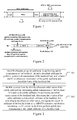
- FIG. 1 is a schematic diagram illustrating a procedure of performing downlink transmission of a relay link by using a MBFSN subframe in the prior art.
- the RN only receives data from the eNB, but does not transmit data to the UE; the "Ctrl” is used for transmitting control signaling to the UE by the RN, i.e., used for performing scheduling for the UE.
- FIG 2 is a schematic diagram illustrating a conventional resource scheduling mode.
- a UE receives Downlink Control Information (DCI) sent by a RN through a Physical Downlink Control Channel (PDCCH), where the DCI contains uplink scheduling information that the RN schedules the UE to perform uplink data transmission in a subfram n+k.
- the UE transmits uplink data to the RN in the subframe n+k through a Physical Uplink Shared Channel (PUSCH).
- DCI Downlink Control Information
- PDCCH Physical Downlink Control Channel
- PUSCH Physical Uplink Shared Channel
- the RN After transmitting the DCI to the UE, the RN receives a DCI sent by the eNB through a Relay Physical Downlink Control Channel (R-PDCCH), where the DCI received by the RN contains uplink scheduling information that the eNB schedules the RN to perform uplink data transmission in the subframe n+k.
- the RN transmits uplink data in the subframe n+k through a Relay Physical Uplink Shared Channel (R-PUSCH). Since the uplink data transmission of the backhaul link or the access link is performed in the whole subframe, in the same subframe, the RN performs a transmission operation for the eNB, and also performs a receiving operation for the UE, which results in uplink transmission conflict.
- R-PDCCH Relay Physical Downlink Control Channel
- R-PUSCH Relay Physical Uplink Shared Channel
- the mode shown in Figure 1 can solve the interference problem, it is unclear in the prior art that how the RN learns which subframe will be taken as a MBSFN subframe. Therefore, the RN can not learn when to receive the R-PDCCH containing the uplink scheduling information sent by the eNB, further it can not be determined when uplink transmission conflict occurs, and thus the uplink transmission conflict can not be solved.
- Examples of the present invention provide a resource scheduling method and system, an eNB and a RN, by which a MBSFN subframe can be indicated to the RN, and uplink transmission conflict can be avoided.
- a resource scheduling method includes:
- a resource scheduling method includes:
- a resource scheduling system includes:
- An eNB includes:
- a RN includes:
- a resource scheduling method includes:
- a resource scheduling method includes:
- a resource scheduling system includes:
- An eNB includes:
- a RN includes:
- the eNB informs the RN of the allocated uplink subframe for performing uplink transmission of the backhaul link and the allocated downlink subframe for performing downlink transmission of the backhaul link.
- the RN may configure the downlink subframe of the backhaul link as a MBSFN subframe in a subsequent procedure, and disables scheduling the UE served by the RN to perform uplink data transmission in the uplink subframe of the backhaul link, so as to avoid uplink transmission conflict.
- the eNB may only inform the RN of the allocated uplink subframe for performing uplink transmission of the backhaul link or the allocated downlink subframe for performing downlink transmission of the backhaul link, and then the RN may self-determine, according to the received informing message and the predefined timing relationship, a downlink subframe for performing downlink transmission of the backhaul link or an uplink subframe for performing uplink transmission of the backhaul link of which the eNB does not inform. In this way, the eNB does not need to inform the RN of the allocated uplink subframe and downlink subframe, so as to decrease signaling overhead.
- the examples of the present invention provide a new resource scheduling method, which includes that: when a RN begins to access a network and does not perform actual communication, an eNB informs the RN of an allocated uplink subframe for performing uplink transmission of a backhaul link and an allocated downlink subframe for performing downlink transmission of the backhaul link, and the RN disables scheduling a UE served by the RN to perform uplink data transmission in the uplink subframe of the backhaul link, and configures the downlink subframe of the backhaul link as a MBSFN subframe.
- the eNB may inform the RN of the uplink subframe for performing uplink transmission of the backhaul link and the downlink subframe for performing downlink transmission of the backhaul link, or only inform the RN of the uplink subframe for performing uplink transmission of the backhaul link or the downlink subframe for performing downlink transmission of the backhaul link.
- the RN determines, according to the uplink subframe of the backhaul link or the downlink subframe of the backhaul link of which the eNB informs and a predefined timing relationship, a downlink subframe or uplink subframe of the backhaul link of which the eNB does not inform.
- FIG. 3 is a schematic flowchart illustrating a resource scheduling method according to a first example of the present invention.
- the eNB informs the RN of the allocated uplink subframe and downlink subframe of the backhaul link.
- the method includes the following steps.
- Step 301 the eNB allocates an uplink subframe for performing uplink transmission of the backhaul link and a downlink subframe for performing downlink transmission of the backhaul link, and informs the RN of allocation information of the uplink subframe and downlink frame of the backhaul link.
- this step it is a conventional technology that how the eNB allocates the uplink subframe for performing uplink transmission of the backhaul link and the downlink subframe for performing downlink transmission of the backhaul link, and will not be described in detail.
- the mode of informing the RN will be described hereinafter in detail.
- One mode of informing the RN includes directly informing the RN of location information of the uplink subframe of the backhaul link and location information of the downlink subframe of the backhaul link.
- a perfect MBSFN subframe informing mode has been provided, but not applied between the eNB and the RN.
- the MBSFN subframe informing mode is a bitmap mode, and includes two cases.
- the bitmap mode may be used to inform the RN of the location of the uplink subframe of the backhaul link and the location of the downlink subframe of the backhaul link.
- a Frequency Division Dual (FDD) mode since an uplink operation and a downlink operation are performed in different frequency bands, two bitmaps are needed to inform the RN of the location of the uplink subframe of the backhaul link and the location of the downlink subframe of the backhaul link.
- downlink subframes 0, 4, 5 and 9 are used to transmit synchronous signals and broadcast messages, thus can not be configured as MBSFN subframes and can not be used to transmit downlink data of the backhaul link.
- the mode A) is adopted, the downlink subframe of the backhaul link is indicated by 6 bits.
- the allocation of the uplink subframe of the backhaul link is not limited, 10 bits are needed to indicate the uplink subframe of the backhaul link, and each bit corresponds to 0 or 1.
- the corresponding bit is configured as 1.
- the uplink subframe and downlink subframe of the backhaul link may be indicated by a uniform bitmap. Since the subframes 0, 1, 5 and 6 can not be configured as MBSFN subframes, in the single radio frame, the uplink subframe and downlink subframe of the backhaul link may be indicated by 6 bits.
- the eNB may inform the RN of the allocated uplink subframe for performing uplink transmission of the backhaul link and the allocated downlink subframe for performing downlink transmission of the backhaul link.
- Another informing mode is as follows. If the allocated subframes of the backhaul link are a subset of a predefined subframe allocation set, the eNB informs the RN of an index value of the subframes of the backhaul linke in the subframe allocation set. For example, for a certain TDD configuration, different subframe allocation may be predefined according to the proportion of different subframes, to form the subframe allocation set. If the subframes of the backhaul link allocated by the eNB are one kind of subframes in the subframe allocation set, it is only needed to inform the RN of the index value of the subframes of the backhaul linke in the subframe allocation set. The RN may determine the allocated subframes of the backhaul link according to a prestored subframe allocation set. The example will be illustrated hereinafter by taking a TDD configuration 1 as an example.
- a first allocation mode an uplink subframe 3 and a downlink subframe 9 are allocated as the subframes of the backhaul link.
- a second allocation mode a downlink subframe 4 and an uplink subframe 8 are allocated as the subframes of the backhaul link.
- a third allocation mode the uplink subframes 3 and 8 and the downlink subframes 4 and 9 are allocated as the subframes of the backhaul link.
- a fourth allocation mode the uplink subframe 3 and the downlink subframes 4 and 9 are allocated as the subframes of the backhaul link.
- a fifth allocation mode the uplink subframe 8 and the downlink subframes 4 and 9 are allocated as the subframes of the backhaul link.
- the index values of the above five allocation modes are 1-5 respectively. If the eNB allocates the downlink subframe 4 and the uplink subrame 8 as the subframes of the backhaul link, the eNB informs the RN of the index value 2. The RN may determine, according to the prestored subframe allocation set, that the downlink subframe 4 and the uplinik subrame 8 are the subframes of the backhaul link.
- the eNB may inform the RN of the location or index value of the subframes of the backhaul link through a broadcast message or a higher-layer signaling.
- the eNB may inform the RN through the broadcast message, so save singling overhead.
- the eNB respectively informs each RN through the higher-layer signaling.
- the higher-layer signaling includes, but is not limited to, a Radio Resourc Control (RRC) signaling.
- RRC Radio Resourc Control
- the eNB may reallocate, according to the quality of the backhaul link and the data quantity of the backhaul link to be transmitted, an uplink subframe for performing uplink transmission of the backhaul link and a downlink subframe for performing downlink transmission of the backhaul link to the RN.
- the reallocation may be triggered by the eNB, or may be triggered by the RN.
- the reallocation may be triggered by the eNB.
- the eNB counts Buffer States Reports (BSRs) which are reported by the RN in a predefined period of time, and adjusts, according to the BSRs, the number of uplink subframes for performing uplink transmission of the backhaul link which are allocated to the RN, i.e., if the buffer state indicates that the quantity of data to be transmitted to the eNB by the RN is large, the eNB increases the number of uplink subframes allocated to the RN; if the buffer state indicates that the quantity of data to be transmitted to the eNB by the RN is small, the eNB decreases the number of uplink subframes allocated to the RN.
- BSRs Buffer States Reports
- the eNB counts buffer states which are transmitted to the RN by the eNB in a predefined period of time, and adjusts, according to the buffer states, the number of downlink subframes for performing downlink transmission of the backhaul link which is allocated to the RN.
- the above procedure of adjusting the number of subframes may be taken as a procedure of reallocating the subframes of the backhaul link.
- the reallocation may be triggered by the RN.
- the RN transmits an adjusting request to the eNB according to the BSR which are reported to the eNB by the RN in a predefined period of time, to request to increase or decrease the number of needed subframes.
- the eNB adjusts, according to the adjusting request, the number of the uplink subframes for performing uplink transmission of the backhaul link which are allocated to the RN.
- the eNB counts buffer states which are transmitted to the RN by the eNB in a predefined period of time, and adjusts, according to the buffer states, the number of the downlink subframes for performing downlink transmission of the backhaul link which are allocated to the RN.
- the above procedure of adjusting the number of subframes may be taken as a procedure of reallocating the subframes of the backhaul link.
- Step 302 the RN receives from the eNB the allocation information of the uplink subframe for performing uplink transmission of the backhaul link and the downlink subframe for performing downlink transmission of the backhaul link, determines the location of the uplink subframe and downlink subframe of the backhaul link according to the allocation information, configures the downlink subframe of the backhaul link as an MBSFN subframe, and disables scheduling the UE served by the RN to perform uplink data transmission in the uplink subframe of the backhaul link.
- the RN after receiving the bitmap or the index value from the eNB, the RN respectively determines the location of the uplink subframe of the backhaul link and the location of the downlink subframe of the backhaul link according to the received information, configures the downlink subframe of the backhaul link as the MBSFN subframe, determines uplink scheduling information in advance according to the determined uplink subframe of the backhaul link, and disables scheduling the UE served by the RN to perform uplink data transmission in the uplink subframe of the backhaul link, so as to avoid uplink transmission conflict.
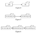
- Figure 4 is a schematic diagram illustrating the structure of a resource scheduling system according to the first example of the present invention. As shown in Figure 4 , the system includes:
- FIG. 5 is a schematic diagram illustrating the structure of an eNB according to the first example of the present invention. As shown in Figure 5 , the eNB includes:
- Figure 6 is a schematic diagram illustrating the structure of a RN according to the first example of the present invention. As shown in Figure 6 , the RN includes:
- the eNB informs the RN of the allocated uplink subframe for performing uplink transmission of the backhaul link and the allocated downlink subframe for performing downlink transmission of the backhaul link.
- the RN may configure the downlink subframe of the backhaul link as an MBSFN subframe, and disable scheduling the UE served by the RN to perform uplink data transmission in the uplink subframe of the backhaul link, so as to avoid uplink transmission conflict.
- the above solution has a problem in practical applications, i.e., since the eNB needs to inform the RN of the uplink subframe for performing uplink transmission of the backhaul link and the downlink subframe for performing downlink transmission of the backhaul link, signaling overhead is large, especially in an instance adopting the FDD mode.
- the eNB allocates the uplink subframe for performing uplink transmission of the backhaul link and the downlink subframe for performing downlink transmission of the backhaul link, and informs the RN of the allocation information of the uplink subframe or downlink subframe of the backhaul link, so that the RN determines, according to a predefined timing relationship, a downlink subframe or uplink subframe of the backhaul link of which the eNB does not inform.
- Figure 7 is a schematic flowchart illustrating a resource scheduling method according to a second example of the present invention. As shown in Figure 7 , the method includes the following steps.
- Step 701 the eNB allocates an uplink subframe for performing uplink transmission of a backhaul link and a downlink subframe for performing downlink transmission of the backhaul link, and informs the RN of the allocation information of the uplink subframe or downlink subframe of the backhaul link.
- the eNB only needs to inform the RN of one kind of subframes of the backhaul link, i.e. the eNB only needs to inform the RN of the allocation information of the uplink subframe for performing uplink transmission of the backhaul link or the downlink subframe for performing downlink transmission of the backhaul link.
- the eNB may inform the RN through a higher-layer signaling or a broadcast message.
- the higher-layer signaling includes, but is not limited to, an RRC signaling.
- Step 702 the RN receives the allocation information of the uplink subframe for performing uplink transmission of the backhaul link or the downlink subframe for performing downlink transmission of the backhaul link from the eNB, and determines the location of the uplink subframe or the downlink subframe of the backhaul link according to the received allocation information.
- the RN may determine that the location corresponding to a bit which is configured as 1 in the bitmap is the location of the uplink subframe or downlink subframe of the backhaul link.
- Step 703 the RN determines, according to the determined location of the uplink subframe or downlink subframe of the backhaul link and a predefined timing relationship, a downlink subframe or uplink subframe of the backhaul link of which the eNB does not inform.
- the predefined timing relationship mentioned herein includes a Hybrid Automatic Repeat Request (HARQ) timing relationship between a downlink subframe for transmitting uplink scheduling information and a corresponding uplink subframe for transmitting PUSCH, or a HARQ timing relationship between a downlink subframe for transmitting Physical Downlink Shared Channel (PDSCH) and a corresponding uplink subframe for transmitting uplink ACK/NACK, or a HARQ relationship between an uplink subframe for transmitting PUSCH and a corresponding downlink subframe for transmitting downlink ACK/NACK.
- HARQ Hybrid Automatic Repeat Request
- the uplink scheduling information is transmitted by the eNB in the downlink subframe, and correspondingly, the PUSCH is transmitted by the RN in the uplink subframe.
- the PDSCH is transmitted by the eNB in the downlink subframe, and correspondingly, the ACK/NACK is transmitted by the eNB in the uplink subframe.
- the PUSCH is transmitted by the RN in the uplink subframe, and correspondingly, the ACK/NACK is transmitted by the eNB in the downlink subframe.
- the RN may determine, according to any one of the above timing relationship, an uplink subframe for performing uplink transmission of the backhaul link or a downlink subframe for performing downlink transmission of the backhaul link of which the eNB does not inform.
- subframes 0, 4, 5 and 9 can not be configured as downlink subframes for performing downlink transmission of the backhaul link, i.e. MBSFN subframes.
- the response location of ACK/NACK and the uplink scheduling location are both related to the uplink and downlink time sequence configuration, for example, if the ACK/NACK is transmitted in the subframe n, a subframe for transmitting the PDSCH is a subframe n-k, where the value of k is as shown in Table 1.
- Table 1 a timing relation between ACK/NACK and PDSCH Uplink-Downlink (UL-DL) Configuration Subframe n 0 1 2 3 4 5 6 7 8 9 0 - - 6 - 4 - - 6 - 4 1 - - 7, 6 4 - - - 7,6 4 - 2 - - 8, 7, 4, 6 - - - - 8, 7, 4, 6 - - 3 - - 7, 6, 11 6, 5 5, 4 - - - - - 4 - 12, 8, 7, 11 6, 5, 4, 7 - - - - - - 5 - - 13, 12, 9, 8, 7, 5, 4,11, 6 - - - - - - - 6 - - 7 7 5 - - 7 7 -
- the PDSCH is transmitted in a subframe 2-6 (suppose the configuration mode 0 is adopted), i.e., the PDSCH is transmitted in the sixth subframe of a radio frame before a radio frame where the subframe 2 is located.
- Table 1 shows 7 configuration modes (the configuration modes 0 and 5 usually are not used). In practical applications, it can be determined, according to practical requirements, which configuration mode is selected. The subsequent similar instances will not be described in detail.
- a subframe for transmitting the PUSCH i.e., the scheduled uplink subframe
- k is as shown in Table 2.
- Table 2 a timing relation between a downlink subframe for transmitting uplink scheduling information and a scheduled uplink subframe TDD UL/DL Configuration DL subframe n 0 1 2 3 4 5 6 7 8 9 0 4 6 4 6 1 6 4 6 4 2 4 4 3 4 4 4 4 4 5 4 6 7 7 7 7 5
- Table 3 a timing relation between PUSCH and ACK/NACK TDD UL/DL Configuration UL subframe n 0 1 2 3 4 5 6 7 8 9 0 4 7 6 4 7 6 1 4 6 4 6 2 6 6 3 6 6 6 4 6 6 5 6 6 4 6 6 4 7
- one of the above three tables to be used may be stored in the RN, and then the RN searches the table according to the received information, to determine the downlink subframe for performing downlink transmission of the backhaul link or the uplink subframe for performing uplink transmission of the backhaul link.
- the RN may determine the downlink subframe for performing downlink transmission of the backhaul link of which the eNB does not inform, where the distance between the location of the uplink subframe for performing uplink transmission of the backhaul link of which the eNB informs and the location of the downlink subframe for performing downlink transmission of the backhaul link of which the eNB does not inform is four subframes.
- the RN may determine the uplink subframe for performing uplink transmission of the backhaul link of which the eNB does not inform, where the distance between the location of the downlink subframe for performing downlink transmission of the backhaul link of which the eNB informs and the location of the uplink subframe for performing uplink transmission of the backhaul link of which the eNB does not inform is four subframes.
- the RN In the TDD mode, the RN needs to search a specific table to determine the uplink subframe or the downlink subframe.
- subframes 0, 1, 5 and 6 can not be configured as downlink subframes for performing downlink transmission of the backhaul link, i.e., MBSFN subframes.
- the RN After determining the uplink subframe or downlink subframe of the backhaul link of which the eNB informs, the RN searches the selected table, and then determines the downlink subframe or uplink subframe of the backhaul link of which the eNB does not inform.
- the FDD mode suppose eNB allocates the downlink subframe 3 of each radio frame as the downlink subframe of the backhaul link, it can be determined, according to the HARQ timing relationship, that the subframe 7 of each radio frame is the uplink subframe of the backhaul link. This subframe configuration mode does not influence the HARQ timing relationship of the access link.
- the eNB allocates the subframe 4 of each radio frame as the downlink subframe of the backhaul link, it can be determined that the subframe 8 of each radio frame is the uplink subframe of the backhaul link according to the HARQ timing relationship between the downlink subframe for transmitting the uplink scheduling information and the uplink subframe for transmitting PUSCH or the HARQ timing relationship between the downlink subframe for transmitting PDSCH and the uplink subframe for transmitting uplink ACK/NACK.
- the uplink and downlink subframe allocation methods in the FDD mode and the TDD mode are only examples, and the specific allocation method includes, but is not limited to, the above two allocation methods.
- the example of the present invention also provides a resource scheduling system, which includes: an eNB, configured to allocate an uplink subframe for performing uplink transmission of a backhaul link and a downlink subframe for performing downlink transmission of the backhaul link, and inform a RN of the allocation information of the uplink subframe or the downlink subframe of the backhaul link; and the RN, configured to receive the allocation information of the uplink subframe for performing uplink transmission of the backhaul link or the downlink subframe for performing downlink transmission of the backhaul link from the eNB, determine the location of the uplink subframe or the downlink subframe of the backhaul link according to the received allocation information, and determine, according to a predefined timing relationship, a downlink subframe or uplink subframe of the backhaul link of which the eNB does not inform.
- a resource scheduling system which includes: an eNB, configured to allocate an uplink subframe for performing uplink transmission of a backhaul link and a downlink subframe for performing downlink
- FIG. 8 is a schematic diagram illustrating the structure of an eNB according to the second example of the present invention. As shown in Figure 8 , the eNB includes:
- Figure 9 is a schematic diagram illustrating the structure of a RN according to the second example of the present invention. As shown in Figure 9 , the RN includes:
- the eNB only informs the RN of the allocated uplink subframe for performing uplink transmission of the backhaul link or the allocated downlink subframe for performing downlink transmission of the backhaul link, and then the RN self-determines, according to the received informing message and the prestored timing relationship, a downlink subframe for performing downlink transmission of the backhaul link or an uplink subframe for performing uplink transmission of the backhaul link of which the eNB does not inform. In this way, the eNB does not need to inform the RN of both the allocated uplink subframe and the allocated downlink subframe at the same time, so as to decrease signaling overhead.
Landscapes
- Engineering & Computer Science (AREA)
- Signal Processing (AREA)
- Computer Networks & Wireless Communication (AREA)
- Multimedia (AREA)
- Mobile Radio Communication Systems (AREA)
Abstract
Description
- The present invention relates to mobile communication technologies, and more particularly to a resource scheduling method and system, a Base Station (BS) and a Relay Node (RN).
- The application of Relay Node (RN) makes a Relay based mobile communication system have three radio links, i.e., an eNB-macro UE direct link, an eNB-RN backhaul link, and a RN-relay UE access link, which are respectively called a direct link, a backhaul link and an access link for short. The transceiver of the RN adopts a Time Division Dual (TDD) mode, i.e., in the TDD mode, the receiving and transmitting can not be performed at the same time.
- The backhaul link and the access link may use the same frequency, but the transmitter of the RN interferes with the receiver of the RN unless signals received by the receiver are completely separated from signals transmitted by the transmitter. And thus, a downlink backhaul link and a downlink access link usually can not use the same frequency resources at the same time, and an uplink backhaul link and an uplink access link also can not use the same frequency resources at the same time. In order to avoid the interference, a following processing mode is usually adopted in the prior art. If the RN receives data from an eNB, the RN does not transmit data to a User Equipment (UE), i.e., a "gap" is created by using a Multicast/Broadcast over a Single Frequency Network (MBSFN) subframe in the transmission time of the downlink access link.
Figure 1 is a schematic diagram illustrating a procedure of performing downlink transmission of a relay link by using a MBFSN subframe in the prior art. As shown inFigure 1 , in the "gap", the RN only receives data from the eNB, but does not transmit data to the UE; the "Ctrl" is used for transmitting control signaling to the UE by the RN, i.e., used for performing scheduling for the UE. - The mode shown in
Figure 1 solves the interference problem, but results in a new problem, which will be illustrated hereinafter. -
Figure 2 is a schematic diagram illustrating a conventional resource scheduling mode. As shown inFigure 2 , in a subframe n, a UE receives Downlink Control Information (DCI) sent by a RN through a Physical Downlink Control Channel (PDCCH), where the DCI contains uplink scheduling information that the RN schedules the UE to perform uplink data transmission in a subfram n+k. Correspondingly, the UE transmits uplink data to the RN in the subframe n+k through a Physical Uplink Shared Channel (PUSCH). After transmitting the DCI to the UE, the RN receives a DCI sent by the eNB through a Relay Physical Downlink Control Channel (R-PDCCH), where the DCI received by the RN contains uplink scheduling information that the eNB schedules the RN to perform uplink data transmission in the subframe n+k. Correspondingly, the RN transmits uplink data in the subframe n+k through a Relay Physical Uplink Shared Channel (R-PUSCH). Since the uplink data transmission of the backhaul link or the access link is performed in the whole subframe, in the same subframe, the RN performs a transmission operation for the eNB, and also performs a receiving operation for the UE, which results in uplink transmission conflict. - In addition, though the mode shown in
Figure 1 can solve the interference problem, it is unclear in the prior art that how the RN learns which subframe will be taken as a MBSFN subframe. Therefore, the RN can not learn when to receive the R-PDCCH containing the uplink scheduling information sent by the eNB, further it can not be determined when uplink transmission conflict occurs, and thus the uplink transmission conflict can not be solved. - Examples of the present invention provide a resource scheduling method and system, an eNB and a RN, by which a MBSFN subframe can be indicated to the RN, and uplink transmission conflict can be avoided.
- In order to achieve the above object, the technical solution of the present invention is implemented as follows.
- A resource scheduling method includes:
- allocating, by an eNodeB (eNB), an uplink subframe for performing uplink transmission of a backhaul link and a downlink subframe for performing downlink transmission of the backhaul link, and informing a Relay Node (RN) of allocation information of the uplink subframe and the downlink frame of the backhaul link, so that the RN disable scheduling a User Equipment (UE) served by the RN to perform uplink data transmission in the uplink subframe of the backhaul link and configures the downlink subframe of the backhaul link as a Multicast/Broadcast over a Single Frequency Network (MBSFN) subframe.
- A resource scheduling method includes:
- receiving, by a Relay Node (RN), allocation information of an uplink subframe for performing uplink transmission of a backhaul link and a downlink subframe for performing downlink transmission of the backhaul link from an eNodeB (eNB);
- determining, location of the uplink subframe and the downlink subframe of the backhaul link according to the allocation information; and
- configuring the downlink subframe of the backhaul link as a Multicast/Broadcast over a Single Frequency Network (MBSFN) subframe, and disabling scheduling a User Equipment (UE) served by the RN to perform uplink data transmission in the uplink subframe of the backhaul link.
- A resource scheduling system includes:
- an eNodeB (eNB), configured to allocate an uplink subframe for performing uplink transmission of a backhaul link and a downlink subframe for performing downlink transmission of the backhaul link, and inform a Relay Node (RN) of allocation information of the uplink subframe and the downlink frame of the backhaul link;
- the RN, configured to receive the allocation information of the uplink subframe for performing uplink transmission of the backhaul link and the downlink subframe for performing downlink transmission of the backhaul link from an eNB, determine location of the uplink subframe and the downlink subframe of the backhaul link according to the allocation information, configure the downlink subframe of the backhaul link as a Multicast/Broadcast over a Single Frequency Network (MBSFN) subframe, and disable scheduling a User Equipment (UE) served by the RN to perform uplink data transmission in the uplink subframe of the backhaul link.
- An eNB includes:
- a first allocating unit, configured to allocate an uplink subframe for performing uplink transmission of a backhaul link and a downlink subframe for performing downlink transmission of the backhaul link;
- a first informing unit, configured to inform a Relay Node (RN) of allocation information of the uplink subframe and the downlink subframe of the backhaul link, so that the RN disables scheduling a User Equipment (UE) served by the RN to perform uplink data transmission in the uplink subframe of the backhaul link, and configures the downlink subframe of the backhaul link as a Multicast/Broadcast over a Single Frequency Network (MBSFN) subframe.
- A RN includes:
- a first receiving unit, configured to receive allocation information of an uplink subframe for performing uplink transmission of a backhaul link and a downlink subframe for performing uplink transmission of the backhaul link from an eNodeB (eNB);
- a first determining unit, configured to determine location of the uplink subframe and the downlink subframe of the backhaul link according to the received allocation information; and
- a first controlling unit, configured to configure the downlink subframe of the backhaul link as a Multicast/Broadcast over a Single Frequency Network (MBSFN) subframe, and disable scheduling a User Equipment (UE) served by the RN to perform uplink data transmission in the uplink subframe of the backhaul link.
- A resource scheduling method includes:
- allocating, by an eNodeB (eNB), an uplink subframe for performing uplink transmission of a backhaul link and a downlink subframe for performing downlink transmission of the backhaul link, and informing a Relay Node (RN) of allocation information of the uplink subframe or the downlink frame of the backhaul link, so that the RN determines an downlink subframe and an uplink subframe of the backhaul link of which the eNB does not inform.
- A resource scheduling method includes:
- receiving, by a Relay Node (RN), allocation information of an uplink subframe for performing uplink transmission of a backhaul link or a downlink subframe for performing downlink transmission of the backhaul link from an eNB, and determining, location of the uplink subframe or the downlink subframe of the backhaul link according to the allocation information;
- determing, by the RN, according to the determined uplink subframe or the downlink subframe of the backhaul link and a predefined timing relationship, an uplink subframe or a downlink subframe of the backhaul link of the eNB does not inform.
- A resource scheduling system includes:
- an eNodeB (eNB), configured to allocate an uplink subframe for performing uplink transmission of a backhaul link and a downlink subframe for performing downlink transmission of the backhaul link, and inform a Relay Node (RN) of allocation information of the uplink subframe or the downlink frame of the backhaul link;
- the RN, configured to receive the allocation information of the uplink subframe or the downlink subframe of the backhaul link from the eNB, determine location of the uplink subframe or the downlink subframe of the backhaul link according to the allocation information, and determine, according to a predefined timing relationship, an downlink subframe or an uplink subframe of the backhaul link of which the eNB does not inform.
- An eNB includes:
- a second allocating unit, configured to allocate an uplink subframe for performing uplink transmission of a backhaul link and a downlink subframe for performing downlink transmission of the backhaul link;
- a second informing unit, configured to inform a Relay Node (RN) of allocation information of the uplink subframe or the downlink frame of the backhaul link, so that the RN determines, according to a predefined timing relationship, an uplink subframe or a downlink subframe of the backhaul link of which the eNB does not inform.
- A RN includes:
- a second receiving unit, configured to receive allocation information of an uplink subframe or a downlink frame of a backhaul link from an eNodeB (eNB);
- a second determining unit, configured to determine location of the uplink subframe or the downlink subframe of the backhaul link according to the allocation information, and determine, according to a predefined timing relationship, a downlink subframe or an uplink subframe of the backhaul link of which the eNB does not inform.
- As can be seen, in the technical solution of the present invention, the eNB informs the RN of the allocated uplink subframe for performing uplink transmission of the backhaul link and the allocated downlink subframe for performing downlink transmission of the backhaul link. In this way, the RN may configure the downlink subframe of the backhaul link as a MBSFN subframe in a subsequent procedure, and disables scheduling the UE served by the RN to perform uplink data transmission in the uplink subframe of the backhaul link, so as to avoid uplink transmission conflict.
- Further, in the technical solution of the present invention, the eNB may only inform the RN of the allocated uplink subframe for performing uplink transmission of the backhaul link or the allocated downlink subframe for performing downlink transmission of the backhaul link, and then the RN may self-determine, according to the received informing message and the predefined timing relationship, a downlink subframe for performing downlink transmission of the backhaul link or an uplink subframe for performing uplink transmission of the backhaul link of which the eNB does not inform. In this way, the eNB does not need to inform the RN of the allocated uplink subframe and downlink subframe, so as to decrease signaling overhead.
- The schematic examples of the present invention will be illustrated hereinafter in detail with reference to the accompany drawings, so as to make those skilled in the art understand the above and other features and merits of the present invention clearly. In the drawings:
-
Figure 1 is a schematic diagram illustrating a procedure of performing downlink transmission of a relay link by using a MBFSN subframe in the prior art. -
Figure 2 is a schematic diagram illustrating a conventional resource scheduling mode. -
Figure 3 is a schematic flowchart illustrating a resource scheduling method according to a first example of the present invention. -
Figure 4 is a schematic diagram illustrating the structure of a resource scheduling system according to the first example of the present invention. -
Figure 5 is a schematic diagram illustrating the structure of an eNB according to the first example of the present invention. -
Figure 6 is a schematic diagram illustrating the structure of a RN according to the first example of the present invention. -
Figure 7 is a schematic flowchart illustrating a resource scheduling method according to a second example of the present invention. -
Figure 8 is a schematic diagram illustrating the structure of an eNB according to the second example of the present invention. -
Figure 9 is a schematic diagram illustrating the structure of a RN according to the second example of the present invention. - In order to solve the problem in the prior art, the examples of the present invention provide a new resource scheduling method, which includes that: when a RN begins to access a network and does not perform actual communication, an eNB informs the RN of an allocated uplink subframe for performing uplink transmission of a backhaul link and an allocated downlink subframe for performing downlink transmission of the backhaul link, and the RN disables scheduling a UE served by the RN to perform uplink data transmission in the uplink subframe of the backhaul link, and configures the downlink subframe of the backhaul link as a MBSFN subframe.
- In practical applications, the eNB may inform the RN of the uplink subframe for performing uplink transmission of the backhaul link and the downlink subframe for performing downlink transmission of the backhaul link, or only inform the RN of the uplink subframe for performing uplink transmission of the backhaul link or the downlink subframe for performing downlink transmission of the backhaul link. The RN determines, according to the uplink subframe of the backhaul link or the downlink subframe of the backhaul link of which the eNB informs and a predefined timing relationship, a downlink subframe or uplink subframe of the backhaul link of which the eNB does not inform.
- The present invention will be described in detail hereinafter with reference to accompanying drawings and examples to make the object, technical solution and merits of the present invention clearer.
-
Figure 3 is a schematic flowchart illustrating a resource scheduling method according to a first example of the present invention. In this example, it is supposed that the eNB informs the RN of the allocated uplink subframe and downlink subframe of the backhaul link. As shown inFigure 3 , the method includes the following steps. - Step 301: the eNB allocates an uplink subframe for performing uplink transmission of the backhaul link and a downlink subframe for performing downlink transmission of the backhaul link, and informs the RN of allocation information of the uplink subframe and downlink frame of the backhaul link.
- In this step, it is a conventional technology that how the eNB allocates the uplink subframe for performing uplink transmission of the backhaul link and the downlink subframe for performing downlink transmission of the backhaul link, and will not be described in detail. The mode of informing the RN will be described hereinafter in detail.
- One mode of informing the RN includes directly informing the RN of location information of the uplink subframe of the backhaul link and location information of the downlink subframe of the backhaul link. In the prior art, a perfect MBSFN subframe informing mode has been provided, but not applied between the eNB and the RN. The MBSFN subframe informing mode is a bitmap mode, and includes two cases.
- A) Bitmap that covers one radio frame BIT STRING (SIZE(6))
- B) Bitmap that covers four continuous radio frames BIT STRING (SIZE(24))
- The bitmap mode may be used to inform the RN of the location of the uplink subframe of the backhaul link and the location of the downlink subframe of the backhaul link.
- In a system adopting a Frequency Division Dual (FDD) mode, since an uplink operation and a downlink operation are performed in different frequency bands, two bitmaps are needed to inform the RN of the location of the uplink subframe of the backhaul link and the location of the downlink subframe of the backhaul link. In each radio frame, downlink subframes 0, 4, 5 and 9 are used to transmit synchronous signals and broadcast messages, thus can not be configured as MBSFN subframes and can not be used to transmit downlink data of the backhaul link. If the mode A) is adopted, the downlink subframe of the backhaul link is indicated by 6 bits. Since the allocation of the uplink subframe of the backhaul link is not limited, 10 bits are needed to indicate the uplink subframe of the backhaul link, and each bit corresponds to 0 or 1. When the corresponding subframe is a subframe of the backhaul link, the corresponding bit is configured as 1.
- In a system adopting a TDD mode, since an uplink operation and a downlink operation are performed in the same frequency band, the uplink subframe and downlink subframe of the backhaul link may be indicated by a uniform bitmap. Since the
subframes 0, 1, 5 and 6 can not be configured as MBSFN subframes, in the single radio frame, the uplink subframe and downlink subframe of the backhaul link may be indicated by 6 bits. - In this example, through the conventional informing modes, the eNB may inform the RN of the allocated uplink subframe for performing uplink transmission of the backhaul link and the allocated downlink subframe for performing downlink transmission of the backhaul link.
- Another informing mode is as follows. If the allocated subframes of the backhaul link are a subset of a predefined subframe allocation set, the eNB informs the RN of an index value of the subframes of the backhaul linke in the subframe allocation set. For example, for a certain TDD configuration, different subframe allocation may be predefined according to the proportion of different subframes, to form the subframe allocation set. If the subframes of the backhaul link allocated by the eNB are one kind of subframes in the subframe allocation set, it is only needed to inform the RN of the index value of the subframes of the backhaul linke in the subframe allocation set. The RN may determine the allocated subframes of the backhaul link according to a prestored subframe allocation set. The example will be illustrated hereinafter by taking a
TDD configuration 1 as an example. - For the
TDD configuration 1, according to the allocation proportion and location of different subframes, there are five modes for allocating the subframes of the backhaul link, so as to form the predefined subframe allocation set. - A first allocation mode: an uplink subframe 3 and a downlink subframe 9 are allocated as the subframes of the backhaul link.
- A second allocation mode: a downlink subframe 4 and an uplink subframe 8 are allocated as the subframes of the backhaul link.
- A third allocation mode: the uplink subframes 3 and 8 and the downlink subframes 4 and 9 are allocated as the subframes of the backhaul link.
- A fourth allocation mode: the uplink subframe 3 and the downlink subframes 4 and 9 are allocated as the subframes of the backhaul link.
- A fifth allocation mode: the uplink subframe 8 and the downlink subframes 4 and 9 are allocated as the subframes of the backhaul link.
- Suppose the index values of the above five allocation modes are 1-5 respectively. If the eNB allocates the downlink subframe 4 and the uplink subrame 8 as the subframes of the backhaul link, the eNB informs the RN of the index value 2. The RN may determine, according to the prestored subframe allocation set, that the downlink subframe 4 and the uplinik subrame 8 are the subframes of the backhaul link.
- It should be noted that, the above description is a schematic example, and will change according to different cases.
- The eNB may inform the RN of the location or index value of the subframes of the backhaul link through a broadcast message or a higher-layer signaling. When the same subframe is allocated to all RNs in a cell served by the eNB, the eNB may inform the RN through the broadcast message, so save singling overhead. When different subframes are allocated to different RNs, the eNB respectively informs each RN through the higher-layer signaling. The higher-layer signaling includes, but is not limited to, a Radio Resourc Control (RRC) signaling.
- In a subsequent procedure, the eNB may reallocate, according to the quality of the backhaul link and the data quantity of the backhaul link to be transmitted, an uplink subframe for performing uplink transmission of the backhaul link and a downlink subframe for performing downlink transmission of the backhaul link to the RN. The reallocation may be triggered by the eNB, or may be triggered by the RN.
- The eNB counts Buffer States Reports (BSRs) which are reported by the RN in a predefined period of time, and adjusts, according to the BSRs, the number of uplink subframes for performing uplink transmission of the backhaul link which are allocated to the RN, i.e., if the buffer state indicates that the quantity of data to be transmitted to the eNB by the RN is large, the eNB increases the number of uplink subframes allocated to the RN; if the buffer state indicates that the quantity of data to be transmitted to the eNB by the RN is small, the eNB decreases the number of uplink subframes allocated to the RN. At the same time, the eNB counts buffer states which are transmitted to the RN by the eNB in a predefined period of time, and adjusts, according to the buffer states, the number of downlink subframes for performing downlink transmission of the backhaul link which is allocated to the RN. The above procedure of adjusting the number of subframes may be taken as a procedure of reallocating the subframes of the backhaul link.
- The RN transmits an adjusting request to the eNB according to the BSR which are reported to the eNB by the RN in a predefined period of time, to request to increase or decrease the number of needed subframes. The eNB adjusts, according to the adjusting request, the number of the uplink subframes for performing uplink transmission of the backhaul link which are allocated to the RN. At the same time, the eNB counts buffer states which are transmitted to the RN by the eNB in a predefined period of time, and adjusts, according to the buffer states, the number of the downlink subframes for performing downlink transmission of the backhaul link which are allocated to the RN. The above procedure of adjusting the number of subframes may be taken as a procedure of reallocating the subframes of the backhaul link.
- Step 302: the RN receives from the eNB the allocation information of the uplink subframe for performing uplink transmission of the backhaul link and the downlink subframe for performing downlink transmission of the backhaul link, determines the location of the uplink subframe and downlink subframe of the backhaul link according to the allocation information, configures the downlink subframe of the backhaul link as an MBSFN subframe, and disables scheduling the UE served by the RN to perform uplink data transmission in the uplink subframe of the backhaul link.
- In this step, after receiving the bitmap or the index value from the eNB, the RN respectively determines the location of the uplink subframe of the backhaul link and the location of the downlink subframe of the backhaul link according to the received information, configures the downlink subframe of the backhaul link as the MBSFN subframe, determines uplink scheduling information in advance according to the determined uplink subframe of the backhaul link, and disables scheduling the UE served by the RN to perform uplink data transmission in the uplink subframe of the backhaul link, so as to avoid uplink transmission conflict.
- Based on the above method,
Figure 4 is a schematic diagram illustrating the structure of a resource scheduling system according to the first example of the present invention. As shown inFigure 4 , the system includes: - an eNB41, configured to allocate an uplink subframe for performing uplink transmission of a backhaul link and a downlink subframe for performing downlink transmission of the backhaul link, and inform a RN42 of the allocation information of the uplink subframe and downlink subframe of the backhaul link; and
- the RN42, configured to receive the allocation information of the uplink subframe and downlink subframe of the backhaul link from the eNB41, determine the location of the uplink subframe and downlink subframe of the backhaul link, configure the downlink subframe of the backhaul link as an MBSFN subframe, and disable scheduling the UE served by the RN to perform uplink data transmission in the uplink subframe of the backhaul link.
-
Figure 5 is a schematic diagram illustrating the structure of an eNB according to the first example of the present invention. As shown inFigure 5 , the eNB includes: - a first allocating
unit 51, configured to allocate an uplink subframe for performing uplink transmission of a backhaul link and a downlink subframe for performing downlink transmission of the backhaul link; - a first informing
unit 52, configured to inform a RN of the allocation information of the uplink subframe and downlink subframe of the backhaul link, so that the RN disables scheduling the UE served by the RN to perform uplink data transmission in the uplink subframe of the backhaul link, and configures the downlink subframe of the backhaul link as an MBSFN subframe. -
Figure 6 is a schematic diagram illustrating the structure of a RN according to the first example of the present invention. As shown inFigure 6 , the RN includes: - a
first receiving unit 61, configured to receive allocation information of an uplink subframe for performing uplink transmission of a backhaul link and a downlink subframe for performing downlink transmission of the backhaul link from an eNB; - a first determining
unit 62, configured to determine the location of the uplink subframe and downlink subframe of the backhaul link according to the received allocation information of the uplink subframe and downlink subframe of the backhaul link; and - a first controlling unit, configured to configure the downlink subframe of the backhaul link as an MBSFN subframe, and disable scheduling the UE served by the RN to perform uplink data transmission in the uplink subframe of the backhaul link.
- The specific working procedure of the system and devices shown in
Figures 4 to 6 may refer to the description of the method example shown inFigure 3 , and will not be illustrated in detail herein. - In the solution shown in
Figures 3 to 6 , the eNB informs the RN of the allocated uplink subframe for performing uplink transmission of the backhaul link and the allocated downlink subframe for performing downlink transmission of the backhaul link. In this way, in a subsequent procedure, the RN may configure the downlink subframe of the backhaul link as an MBSFN subframe, and disable scheduling the UE served by the RN to perform uplink data transmission in the uplink subframe of the backhaul link, so as to avoid uplink transmission conflict. - However, the above solution has a problem in practical applications, i.e., since the eNB needs to inform the RN of the uplink subframe for performing uplink transmission of the backhaul link and the downlink subframe for performing downlink transmission of the backhaul link, signaling overhead is large, especially in an instance adopting the FDD mode.
- Therefore, in the solution of the present invention, the eNB allocates the uplink subframe for performing uplink transmission of the backhaul link and the downlink subframe for performing downlink transmission of the backhaul link, and informs the RN of the allocation information of the uplink subframe or downlink subframe of the backhaul link, so that the RN determines, according to a predefined timing relationship, a downlink subframe or uplink subframe of the backhaul link of which the eNB does not inform.
-
Figure 7 is a schematic flowchart illustrating a resource scheduling method according to a second example of the present invention. As shown inFigure 7 , the method includes the following steps. - Step 701: the eNB allocates an uplink subframe for performing uplink transmission of a backhaul link and a downlink subframe for performing downlink transmission of the backhaul link, and informs the RN of the allocation information of the uplink subframe or downlink subframe of the backhaul link.
- It is a conventional technology that how the eNB allocates the uplink subframe for performing uplink transmission of the backhaul link and the downlink subframe for performing downlink transmission of the backhaul link, and will not be described in detail.
- In this example, the eNB only needs to inform the RN of one kind of subframes of the backhaul link, i.e. the eNB only needs to inform the RN of the allocation information of the uplink subframe for performing uplink transmission of the backhaul link or the downlink subframe for performing downlink transmission of the backhaul link. Specifically, the eNB may inform the RN through a higher-layer signaling or a broadcast message. The higher-layer signaling includes, but is not limited to, an RRC signaling.
- Step 702: the RN receives the allocation information of the uplink subframe for performing uplink transmission of the backhaul link or the downlink subframe for performing downlink transmission of the backhaul link from the eNB, and determines the location of the uplink subframe or the downlink subframe of the backhaul link according to the received allocation information.
- In this example, suppose the eNB informs the RN of the allocation information of the uplink subframe or downlink subframe of the backhaul link through a bitmap mode, the RN may determine that the location corresponding to a bit which is configured as 1 in the bitmap is the location of the uplink subframe or downlink subframe of the backhaul link.
- Step 703: the RN determines, according to the determined location of the uplink subframe or downlink subframe of the backhaul link and a predefined timing relationship, a downlink subframe or uplink subframe of the backhaul link of which the eNB does not inform.
- The predefined timing relationship mentioned herein includes a Hybrid Automatic Repeat Request (HARQ) timing relationship between a downlink subframe for transmitting uplink scheduling information and a corresponding uplink subframe for transmitting PUSCH, or a HARQ timing relationship between a downlink subframe for transmitting Physical Downlink Shared Channel (PDSCH) and a corresponding uplink subframe for transmitting uplink ACK/NACK, or a HARQ relationship between an uplink subframe for transmitting PUSCH and a corresponding downlink subframe for transmitting downlink ACK/NACK.
- In the backhaul link, the uplink scheduling information is transmitted by the eNB in the downlink subframe, and correspondingly, the PUSCH is transmitted by the RN in the uplink subframe. The PDSCH is transmitted by the eNB in the downlink subframe, and correspondingly, the ACK/NACK is transmitted by the eNB in the uplink subframe. The PUSCH is transmitted by the RN in the uplink subframe, and correspondingly, the ACK/NACK is transmitted by the eNB in the downlink subframe.
- The above timing relationships have been defined in the prior art, and the following is some examples.
- In the FDD mode, if the PDSCH or the PUSCH is transmitted in a subframe n, the ACK/NACK is transmitted in a subframe n+4. If the uplink scheduling information is transmitted in the subframe n, the PUSCH is transmitted in the subframe n+4. That is to say, in the FDD mode, no matter which timing relationship is adopted, the distance between the location of the uplink subframe and the location of the downlink subframe is 4ms (the length of each subframe is 1ms). And thus, the RN may determine, according to any one of the above timing relationship, an uplink subframe for performing uplink transmission of the backhaul link or a downlink subframe for performing downlink transmission of the backhaul link of which the eNB does not inform. Generally, subframes 0, 4, 5 and 9 can not be configured as downlink subframes for performing downlink transmission of the backhaul link, i.e. MBSFN subframes.
- In the TDD mode, the response location of ACK/NACK and the uplink scheduling location are both related to the uplink and downlink time sequence configuration, for example,
if the ACK/NACK is transmitted in the subframe n, a subframe for transmitting the PDSCH is a subframe n-k, where the value of k is as shown in Table 1.Table 1 a timing relation between ACK/NACK and PDSCH Uplink-Downlink (UL-DL) Configuration Subframe n 0 1 2 3 4 5 6 7 8 9 0 - - 6 - 4 - - 6 - 4 1 - - 7, 6 4 - - - 7,6 4 - 2 - - 8, 7, 4, 6 - - - - 8, 7, 4, 6 - - 3 - - 7, 6, 11 6, 5 5, 4 - - - - - 4 - - 12, 8, 7, 11 6, 5, 4, 7 - - - - - - 5 - - 13, 12, 9, 8, 7, 5, 4,11, 6 - - - - - - - 6 - - 7 7 5 - - 7 7 - - If the ACK/NACK is transmitted in a subframe 2, the PDSCH is transmitted in a subframe 2-6 (suppose the configuration mode 0 is adopted), i.e., the PDSCH is transmitted in the sixth subframe of a radio frame before a radio frame where the subframe 2 is located. It should be noted that, Table 1 shows 7 configuration modes (the configuration modes 0 and 5 usually are not used). In practical applications, it can be determined, according to practical requirements, which configuration mode is selected. The subsequent similar instances will not be described in detail.
- If the uplink scheduling information is transmitted in the subframe n, a subframe for transmitting the PUSCH, i.e., the scheduled uplink subframe, is n+k. The value of k is as shown in Table 2.
Table 2 a timing relation between a downlink subframe for transmitting uplink scheduling information and a scheduled uplink subframe TDD UL/DL Configuration DL subframe n 0 1 2 3 4 5 6 7 8 9 0 4 6 4 6 1 6 4 6 4 2 4 4 3 4 4 4 4 4 4 5 4 6 7 7 7 7 5 - If the PUSCH is transmitted in the subframe n, the ACK/NACK is transmitted in the subframe n+k. The value of k is as shown in Table 3.
Table 3 a timing relation between PUSCH and ACK/NACK TDD UL/DL Configuration UL subframe n 0 1 2 3 4 5 6 7 8 9 0 4 7 6 4 7 6 1 4 6 4 6 2 6 6 3 6 6 6 4 6 6 5 6 6 4 6 6 4 7 - In this example, one of the above three tables to be used may be stored in the RN, and then the RN searches the table according to the received information, to determine the downlink subframe for performing downlink transmission of the backhaul link or the uplink subframe for performing uplink transmission of the backhaul link.
- In the FDD mode, since the distance between the location of uplink subframe and the location of the downlink subframe is fixed, the RN may determine the downlink subframe for performing downlink transmission of the backhaul link of which the eNB does not inform, where the distance between the location of the uplink subframe for performing uplink transmission of the backhaul link of which the eNB informs and the location of the downlink subframe for performing downlink transmission of the backhaul link of which the eNB does not inform is four subframes. Similarly, the RN may determine the uplink subframe for performing uplink transmission of the backhaul link of which the eNB does not inform, where the distance between the location of the downlink subframe for performing downlink transmission of the backhaul link of which the eNB informs and the location of the uplink subframe for performing uplink transmission of the backhaul link of which the eNB does not inform is four subframes.
- In the TDD mode, the RN needs to search a specific table to determine the uplink subframe or the downlink subframe. Generally,
subframes 0, 1, 5 and 6 can not be configured as downlink subframes for performing downlink transmission of the backhaul link, i.e., MBSFN subframes. After determining the uplink subframe or downlink subframe of the backhaul link of which the eNB informs, the RN searches the selected table, and then determines the downlink subframe or uplink subframe of the backhaul link of which the eNB does not inform. - In the FDD mode, suppose eNB allocates the downlink subframe 3 of each radio frame as the downlink subframe of the backhaul link, it can be determined, according to the HARQ timing relationship, that the subframe 7 of each radio frame is the uplink subframe of the backhaul link. This subframe configuration mode does not influence the HARQ timing relationship of the access link.
- In the
TDD configuration 1, suppose the eNB allocates the subframe 4 of each radio frame as the downlink subframe of the backhaul link, it can be determined that the subframe 8 of each radio frame is the uplink subframe of the backhaul link according to the HARQ timing relationship between the downlink subframe for transmitting the uplink scheduling information and the uplink subframe for transmitting PUSCH or the HARQ timing relationship between the downlink subframe for transmitting PDSCH and the uplink subframe for transmitting uplink ACK/NACK. - It should be noted that, the uplink and downlink subframe allocation methods in the FDD mode and the TDD mode are only examples, and the specific allocation method includes, but is not limited to, the above two allocation methods.
- Based on the above method, the example of the present invention also provides a resource scheduling system, which includes: an eNB, configured to allocate an uplink subframe for performing uplink transmission of a backhaul link and a downlink subframe for performing downlink transmission of the backhaul link, and inform a RN of the allocation information of the uplink subframe or the downlink subframe of the backhaul link; and
the RN, configured to receive the allocation information of the uplink subframe for performing uplink transmission of the backhaul link or the downlink subframe for performing downlink transmission of the backhaul link from the eNB, determine the location of the uplink subframe or the downlink subframe of the backhaul link according to the received allocation information, and determine, according to a predefined timing relationship, a downlink subframe or uplink subframe of the backhaul link of which the eNB does not inform. -
Figure 8 is a schematic diagram illustrating the structure of an eNB according to the second example of the present invention. As shown inFigure 8 , the eNB includes: - a second allocating
unit 81, configured to allocate an uplink subframe for performing uplink transmission of a backhaul link and a downlink subframe for performing downlink transmission of the backhaul link; - a second informing
unit 82, configured to inform a RN of the allocation information of the uplink subframe or the downlink subframe of the backhaul link, so that the RN determines, according to a predefined timing relationship, a downlink subframe or uplink subframes of the backhaul link of which the eNB does not informs. -
Figure 9 is a schematic diagram illustrating the structure of a RN according to the second example of the present invention. As shown inFigure 9 , the RN includes: - a
second receiving unit 91, configured to receive allocation information of an uplink subframe for performing uplink transmission of a backhaul link and a downlink subframes for performing downlink transmission of the backhaul link from an eNB; - a second determining
unit 92, configured to determine the location of the uplink subframe and downlink subframe of the backhaul link according to the received allocation information, and determine, according to a predefined timing relationship, a downlink subframe or uplink subframe of the backhaul link of which the eNB does not informs. - In the technical solution as shown in
Figures 7 to 9 , the eNB only informs the RN of the allocated uplink subframe for performing uplink transmission of the backhaul link or the allocated downlink subframe for performing downlink transmission of the backhaul link, and then the RN self-determines, according to the received informing message and the prestored timing relationship, a downlink subframe for performing downlink transmission of the backhaul link or an uplink subframe for performing uplink transmission of the backhaul link of which the eNB does not inform. In this way, the eNB does not need to inform the RN of both the allocated uplink subframe and the allocated downlink subframe at the same time, so as to decrease signaling overhead. - The foregoing is only the preferred examples of the present invention and is not used to limit the protection scope of the present invention. Any modification, equivalent substitution and improvement without departing from the principle of the present invention are within the protection scope of the present invention.
Claims (23)
- A resource scheduling method, comprising:allocating, by an eNodeB (eNB), an uplink subframe for performing uplink transmission of a backhaul link and a downlink subframe for performing downlink transmission of the backhaul link, and informing a Relay Node (RN) of allocation information of the uplink subframe and the downlink frame of the backhaul link, so that the RN disable scheduling a User Equipment (UE) served by the RN to perform uplink data transmission in the uplink subframe of the backhaul link and configures the downlink subframe of the backhaul link as a Multicast/Broadcast over a Single Frequency Network (MBSFN) subframe.
- The method of claim 1, wherein informing a RN of allocation information of the uplink subframe and the downlink frame of the backhaul link comprises:informing, by the eNB, the RN of location information of the uplink subframe and the downlink subframe of the backhaul link.
- The method of claim 1, wherein informing a RN of allocation information of the uplink subframe and the downlink frame of the backhaul link comprises:when the uplink subframe and the downlink subframe of the backhaul link are a subset of a predefined subframe allocation set, informing, by the eNB, the RN of an index value of the uplink subframe and the downlink subframe of the backhaul link in the predefined subframe allocation set.
- The method of claim 1, wherein informing a RN of allocation information of the uplink subframe and the downlink frame of the backhaul link comprises:informing, by the eNB, the RN of the allocation information of the uplink subframe and the downlink frame of the backhaul link through a higher-layer signaling or a broadcast message.
- The method of any of claims 1 to 4, further comprising:reallocating, by the eNB, a new uplink subframe and a new downlink frame of the backhaul link according to the quality of the backhaul link and data quantity of the backhaul link, and informing the RN of allocation information of the new uplink subframe and the new downlink frame of the backhaul link.
- A resource scheduling method, comprising:receiving, by a Relay Node (RN), allocation information of an uplink subframe for performing uplink transmission of a backhaul link and a downlink subframe for performing downlink transmission of the backhaul link from an eNodeB (eNB);determining, location of the uplink subframe and the downlink subframe of the backhaul link according to the allocation information; andconfiguring the downlink subframe of the backhaul link as a Multicast/Broadcast over a Single Frequency Network (MBSFN) subframe, and disabling scheduling a User Equipment (UE) served by the RN to perform uplink data transmission in the uplink subframe of the backhaul link.
- The method of claim 6, wherein receiving, by a RN, allocation information of an uplink subframe for performing uplink transmission of a backhaul link and a downlink subframe for performing downlink transmission of the backhaul link from an eNB comprises:receiving location information of the uplink subframe and the downlink subframe of the backhaul link from the eNB.
- The method of claim 6, wherein receiving, by a RN, allocation information of an uplink subframe for performing uplink transmission of a backhaul link and a downlink subframe for performing downlink transmission of the backhaul link from an eNB comprises:when the uplink subframe and the downlink subframe of the backhaul link are a subset of a predefined subframe allocation set, receiving, by the RN, an index value of the uplink subframe and the downlink subframe of the backhaul link in the predefined subframe allocation set from the eNB.
- The method of claim 6, wherein receiving, by a RN, allocation information of an uplink subframe for performing uplink transmission of a backhaul link and a downlink subframe for performing downlink transmission of the backhaul link from an eNB comprises:receiving, by the RN, the allocation information of the uplink subframe and the downlink frame of the backhaul link which is transmitted by the eNB through a higher-layer signaling or a broadcast message.
- The method of any of claims 6 to 9, further comprising:receiving, by the RN, reallocated uplink subframe and downlink frame of the backhaul link from the eNB, and determining location of the reallocated uplink subframe and downlink frame of the backhaul link.
- A resource scheduling system, comprising:an eNodeB (eNB), configured to allocate an uplink subframe for performing uplink transmission of a backhaul link and a downlink subframe for performing downlink transmission of the backhaul link, and inform a Relay Node (RN) of allocation information of the uplink subframe and the downlink frame of the backhaul link;the RN, configured to receive the allocation information of the uplink subframe for performing uplink transmission of the backhaul link and the downlink subframe for performing downlink transmission of the backhaul link from an eNB, determine location of the uplink subframe and the downlink subframe of the backhaul link according to the allocation information, configure the downlink subframe of the backhaul link as a Multicast/Broadcast over a Single Frequency Network (MBSFN) subframe, and disable scheduling a User Equipment (UE) served by the RN to perform uplink data transmission in the uplink subframe of the backhaul link.
- An eNodeB (eNB), comprising:a first allocating unit, configured to allocate an uplink subframe for performing uplink transmission of a backhaul link and a downlink subframe for performing downlink transmission of the backhaul link;a first informing unit, configured to inform a Relay Node (RN) of allocation information of the uplink subframe and the downlink subframe of the backhaul link, so that the RN disables scheduling a User Equipment (UE) served by the RN to perform uplink data transmission in the uplink subframe of the backhaul link, and configures the downlink subframe of the backhaul link as a Multicast/Broadcast over a Single Frequency Network (MBSFN) subframe.
- A Relay Node (RN), comprising:a first receiving unit, configured to receive allocation information of an uplink subframe for performing uplink transmission of a backhaul link and a downlink subframe for performing uplink transmission of the backhaul link from an eNodeB (eNB);a first determining unit, configured to determine location of the uplink subframe and the downlink subframe of the backhaul link according to the received allocation information; anda first controlling unit, configured to configure the downlink subframe of the backhaul link as a Multicast/Broadcast over a Single Frequency Network (MBSFN) subframe, and disable scheduling a User Equipment (UE) served by the RN to perform uplink data transmission in the uplink subframe of the backhaul link.
- A resource scheduling method, comprising:allocating, by an eNodeB (eNB), an uplink subframe for performing uplink transmission of a backhaul link and a downlink subframe for performing downlink transmission of the backhaul link, and informing a Relay Node (RN) of allocation information of the uplink subframe or the downlink frame of the backhaul link, so that the RN determines an downlink subframe and an uplink subframe of the backhaul link of which the eNB does not inform.
- The method of claim 14, wherein informing a RN of allocation information of the uplink subframe or the downlink frame of the backhaul link comprises:informing, by the eNB, the RN of the allocation information of the uplink subframe or the downlink frame of the backhaul link through a higher-layer signaling or a broadcast message.
- The method of claim 14 or 15, further comprising:reallocating, by the eNB, new uplink subframe and downlink frame of the backhaul link according to the quality of the backhaul link and data quantity of the backhaul link, and informing the RN of allocation information of the new uplink subframe and downlink frame of the backhaul link.
- A resource scheduling method, comprising:receiving, by a Relay Node (RN), allocation information of an uplink subframe for performing uplink transmission of a backhaul link or a downlink subframe for performing downlink transmission of the backhaul link from an eNB, and determining, location of the uplink subframe or the downlink subframe of the backhaul link according to the allocation information;determing, by the RN, according to the determined uplink subframe or the downlink subframe of the backhaul link and a predefined timing relationship, an uplink subframe or a downlink subframe of the backhaul link of the eNB does not inform.
- The method of claim 17, wherein receiving, by a RN, allocation information of an uplink subframe for performing uplink transmission of a backhaul link or a downlink subframe for performing downlink transmission of the backhaul link from an eNB comprises:receiving, by the RN, the allocation information of the uplink subframe or the downlink frame of the backhaul link which is transmitted by the eNB through a higher-layer signaling or a broadcast message.
- The method of claim 17, wherein the predefined timing relationship comprising:a Hybrid Automatic Repeat Request (HARQ) timing relationship between a downlink subframe for transmitting uplink scheduling information and an uplink subframe for transmitting Physical Uplink Shared Channel (PUSCH), ora HARQ timing relationship between a downlink subframe for transmitting Physical Downlink Shared Channel (PDSCH) and an uplink subframe for transmitting uplink ACK/NACK, ora HARQ timing relation between an uplink subframe for transmitting PUSCH and a downlink subframe for transmitting downlink ACK/NACK.
- The method of claim 17 or 18, further comprising:receiving, by the RN, allocation information of reallocated uplink subframe or downlink subframe of the backhaul link, and determining location of the uplink subframe or the downlink subframe of the backhaul link again.
- A resource scheduling system, comprising:an eNodeB (eNB), configured to allocate an uplink subframe for performing uplink transmission of a backhaul link and a downlink subframe for performing downlink transmission of the backhaul link, and inform a Relay Node (RN) of allocation information of the uplink subframe or the downlink frame of the backhaul link;the RN, configured to receive the allocation information of the uplink subframe or the downlink subframe of the backhaul link from the eNB, determine location of the uplink subframe or the downlink subframe of the backhaul link according to the allocation information, and determine, according to a predefined timing relationship, an downlink subframe or an uplink subframe of the backhaul link of which the eNB does not inform.
- An eNodeB (eNB), comprising:a second allocating unit, configured to allocate an uplink subframe for performing uplink transmission of a backhaul link and a downlink subframe for performing downlink transmission of the backhaul link;a second informing unit, configured to inform a Relay Node (RN) of allocation information of the uplink subframe or the downlink frame of the backhaul link, so that the RN determines, according to a predefined timing relationship, an uplink subframe or a downlink subframe of the backhaul link of which the eNB does not inform.
- A Relay Node (RN), comprising:a second receiving unit, configured to receive allocation information of an uplink subframe or a downlink frame of a backhaul link from an eNodeB (eNB);a second determining unit, configured to determine location of the uplink subframe or the downlink subframe of the backhaul link according to the allocation information, and determine, according to a predefined timing relationship, a downlink subframe or an uplink subframe of the backhaul link of which the eNB does not inform.
Applications Claiming Priority (3)
| Application Number | Priority Date | Filing Date | Title |
|---|---|---|---|
| CN200910082030A CN101867944B (en) | 2009-04-17 | 2009-04-17 | Method and system for scheduling resources, evolved node B (eNB) and relay node (RN) |
| CN200910082260A CN101867406B (en) | 2009-04-20 | 2009-04-20 | Method and system for acquiring subframe positions, evolved node B (eNB) and relay node (RN) |
| PCT/CN2010/071864 WO2010118705A1 (en) | 2009-04-17 | 2010-04-19 | Resource scheduling method and system, base station and relay node |
Publications (3)
| Publication Number | Publication Date |
|---|---|
| EP2421299A1 true EP2421299A1 (en) | 2012-02-22 |
| EP2421299A4 EP2421299A4 (en) | 2012-11-07 |
| EP2421299B1 EP2421299B1 (en) | 2015-09-09 |
Family
ID=42982136
Family Applications (1)
| Application Number | Title | Priority Date | Filing Date |
|---|---|---|---|
| EP10764118.5A Active EP2421299B1 (en) | 2009-04-17 | 2010-04-19 | Resource scheduling method and system, base station and relay node |
Country Status (4)
| Country | Link |
|---|---|
| US (1) | US20120044852A1 (en) |
| EP (1) | EP2421299B1 (en) |
| KR (1) | KR101224098B1 (en) |
| WO (1) | WO2010118705A1 (en) |
Cited By (3)
| Publication number | Priority date | Publication date | Assignee | Title |
|---|---|---|---|---|
| WO2012110957A1 (en) * | 2011-02-14 | 2012-08-23 | Telefonaktiebolaget L M Ericsson (Publ) | Harq handling at relay node reconfiguration |
| CN103338097A (en) * | 2013-07-23 | 2013-10-02 | 北京中科晶上科技有限公司 | Method and system for HARQ (Hybrid Automatic Repeat Request) data processing |
| EP2611246A4 (en) * | 2010-08-23 | 2013-11-20 | Huawei Tech Co Ltd | METHOD AND DEVICE FOR ALLOCATING A LAND BOND RESOURCE |
Families Citing this family (14)
| Publication number | Priority date | Publication date | Assignee | Title |
|---|---|---|---|---|
| US8861424B2 (en) * | 2009-07-06 | 2014-10-14 | Qualcomm Incorporated | Downlink control channel for relay resource allocation |
| US9025517B2 (en) * | 2009-08-14 | 2015-05-05 | Nokia Coporation | Flexible ways to indicate downlink/uplink backhaul subframe configurations in a relay system |
| GB2498571A (en) | 2012-01-20 | 2013-07-24 | Intellectual Ventures Holding 81 Llc | Base station able to communicate with a second device type on a narrow subset frequency band contained within a first main band |
| WO2013116988A1 (en) * | 2012-02-07 | 2013-08-15 | Nokia Corporation | Method and apparatus to report and handle buffer status for user equipment working in inter-site carrier aggregation mode |
| US9425925B2 (en) | 2012-03-26 | 2016-08-23 | Lg Electronics Inc. | Method for operating HARQ to change dynamic resource of wiress resource in wireless communication system, and apparatus therefor |
| WO2014171794A1 (en) * | 2013-04-18 | 2014-10-23 | 엘지전자 주식회사 | Methods and devices for transmitting scheduling request in wireless access system |
| KR102235176B1 (en) * | 2013-06-26 | 2021-04-02 | 엘지전자 주식회사 | Method for supporting discontinuous reception and apparatus therefor in wireless communication system supporting reconfiguration of wireless resource |
| RU2641675C1 (en) * | 2014-02-27 | 2018-01-19 | Хуавэй Текнолоджиз Ко., Лтд. | Base station, small cell and scheduling method for communication line resource |
| KR102347405B1 (en) * | 2015-01-19 | 2022-01-06 | 삼성전자주식회사 | Apparatus and method for cooperative transmission scheduling in wireless communication system |
| US10383136B2 (en) | 2015-08-24 | 2019-08-13 | Qualcomm Incorporated | Methods an apparatus for backhaul and access link scheduling in integrated access and backhaul network and synchronized networks |
| US9894679B2 (en) * | 2016-03-18 | 2018-02-13 | Qualcomm Incorporated | Dynamic adjustment of downlink and uplink traffic scheduling |
| CN110167174B (en) * | 2018-02-14 | 2023-07-28 | 华为技术有限公司 | Relay transmission method and device |
| US10841942B2 (en) * | 2018-04-05 | 2020-11-17 | Qualcomm Incorporated | Scheduling and time-domain configuration in integrated access and backhaul |
| JP7361201B2 (en) * | 2020-03-25 | 2023-10-13 | 京セラ株式会社 | Communication control method and relay user device |
Family Cites Families (12)
| Publication number | Priority date | Publication date | Assignee | Title |
|---|---|---|---|---|
| GB2406018B (en) * | 2003-09-09 | 2005-08-10 | Motorola Inc | Wireless communication system, wireless communication unit and method of routeing a communication |
| KR20070031173A (en) | 2005-09-14 | 2007-03-19 | 삼성전자주식회사 | Apparatus and method for supporting multiple links in a multihop relay cellular network |
| CN100589633C (en) * | 2006-07-10 | 2010-02-10 | 华为技术有限公司 | Relay forwarding method for broadband wireless access |
| CN101106807B (en) * | 2006-07-12 | 2012-04-11 | 株式会社Ntt都科摩 | A cellular network based on relay and space division duplex communication method |
| ES2628086T3 (en) * | 2007-03-19 | 2017-08-01 | Telefonaktiebolaget Lm Ericsson (Publ) | Broadcasting of the channel status return information in a telecommunication system |
| EP2056512B1 (en) * | 2007-09-08 | 2018-02-14 | Samsung Electronics Co., Ltd. | Apparatus and method for determining time to response of retransmission in a multihop relay wireless comunication system |
| KR20090078723A (en) * | 2008-01-15 | 2009-07-20 | 삼성전자주식회사 | Signal Transmission / Reception Method Based on Hybrid Automatic Retransmission Request Scheme in Wireless Mobile Communication System |
| US9294219B2 (en) * | 2008-09-30 | 2016-03-22 | Qualcomm Incorporated | Techniques for supporting relay operation in wireless communication systems |
| US9203564B2 (en) * | 2008-10-20 | 2015-12-01 | Qualcomm Incorporated | Data transmission via a relay station in a wireless communication system |
| KR101584814B1 (en) * | 2008-12-23 | 2016-01-13 | 엘지전자 주식회사 | Method and apparatus for transmitting scheduling request in wireless communication system |
| WO2010107230A2 (en) * | 2009-03-18 | 2010-09-23 | Lg Electronics Inc. | Method and apparatus for transmitting reference signal in wireless communication system |
| EP2409444A2 (en) * | 2009-03-20 | 2012-01-25 | Telefonaktiebolaget LM Ericsson (publ) | Hybrid-arq mechanism for cooperative base stations uplink |
-
2010
- 2010-04-19 WO PCT/CN2010/071864 patent/WO2010118705A1/en not_active Ceased
- 2010-04-19 EP EP10764118.5A patent/EP2421299B1/en active Active
- 2010-04-19 KR KR1020117027401A patent/KR101224098B1/en active Active
-
2011
- 2011-10-17 US US13/275,285 patent/US20120044852A1/en not_active Abandoned
Non-Patent Citations (4)
| Title |
|---|
| NOKIA ET AL: "Considerations on TDD Relay", 3GPP DRAFT; R1-090244, 3RD GENERATION PARTNERSHIP PROJECT (3GPP), MOBILE COMPETENCE CENTRE ; 650, ROUTE DES LUCIOLES ; F-06921 SOPHIA-ANTIPOLIS CEDEX ; FRANCE, no. Ljubljana; 20090107, 7 January 2009 (2009-01-07), XP050318172, [retrieved on 2009-01-07] * |
| NORTEL: "Discussion paper on the control channel and data channel optimization for relay link", 3GPP DRAFT; R1-091384(NORTEL-CONTROL_DATA_RELAY_LINK_D ESIGN_IN_LTE-A), 3RD GENERATION PARTNERSHIP PROJECT (3GPP), MOBILE COMPETENCE CENTRE ; 650, ROUTE DES LUCIOLES ; F-06921 SOPHIA-ANTIPOLIS CEDEX ; FRANCE, no. Seoul, Korea; 20090317, 17 March 2009 (2009-03-17), XP050338973, [retrieved on 2009-03-17] * |
| See also references of WO2010118705A1 * |
| ZTE: "Control Channel Structure and Mapping Pattern of Backhaul Link", 3GPP DRAFT; R1-091424 CONTROL CHANNEL STRUCTURE AND MAPPING PATTERN OF BACKHAUL LINK, 3RD GENERATION PARTNERSHIP PROJECT (3GPP), MOBILE COMPETENCE CENTRE ; 650, ROUTE DES LUCIOLES ; F-06921 SOPHIA-ANTIPOLIS CEDEX ; FRANCE, no. Seoul, Korea; 20090317, 17 March 2009 (2009-03-17), XP050339004, [retrieved on 2009-03-17] * |
Cited By (6)
| Publication number | Priority date | Publication date | Assignee | Title |
|---|---|---|---|---|
| EP2611246A4 (en) * | 2010-08-23 | 2013-11-20 | Huawei Tech Co Ltd | METHOD AND DEVICE FOR ALLOCATING A LAND BOND RESOURCE |
| US9345022B2 (en) | 2010-08-23 | 2016-05-17 | Huawei Technologies Co., Ltd. | Method and device for allocating backhaul link resource |
| WO2012110957A1 (en) * | 2011-02-14 | 2012-08-23 | Telefonaktiebolaget L M Ericsson (Publ) | Harq handling at relay node reconfiguration |
| US8958364B2 (en) | 2011-02-14 | 2015-02-17 | Telefonaktiebolaget L M Ericsson (Publ) | HARQ handling at relay node reconfiguration |
| CN103338097A (en) * | 2013-07-23 | 2013-10-02 | 北京中科晶上科技有限公司 | Method and system for HARQ (Hybrid Automatic Repeat Request) data processing |
| CN103338097B (en) * | 2013-07-23 | 2016-05-25 | 北京中科晶上科技有限公司 | The method and system of HARQ data processing |
Also Published As
| Publication number | Publication date |
|---|---|
| WO2010118705A1 (en) | 2010-10-21 |
| US20120044852A1 (en) | 2012-02-23 |
| KR101224098B1 (en) | 2013-01-21 |
| EP2421299A4 (en) | 2012-11-07 |
| EP2421299B1 (en) | 2015-09-09 |
| KR20120005515A (en) | 2012-01-16 |
Similar Documents
| Publication | Publication Date | Title |
|---|---|---|
| EP2421299B1 (en) | Resource scheduling method and system, base station and relay node | |
| US12232144B2 (en) | System and method for supporting inter-band carrier aggregation with different UL/DL TDD configurations | |
| EP2759072B1 (en) | Hybrid in-band/out-of-band relays | |
| EP2697921B1 (en) | Method and apparatus for operating subframe and transmitting channel informaiton for controlling interference in communication system | |
| US10045351B2 (en) | Systems and methods for different TDD configurations in carrier aggregation | |
| EP2901602B1 (en) | Transmission of uplink control information in inter-enb carrier aggregation | |
| EP2695312B1 (en) | Flexible adjustment of uplink and downlink ratio configuration | |
| KR102197238B1 (en) | Method and apparatus for transmitting channel state information in wireless communication system | |
| EP3096579A1 (en) | User terminal, radio base station, and radio communication method | |
| EP3185457B1 (en) | Response information transmission method, apparatus and device | |
| EP2482603B1 (en) | Method and device for implementing asymmetrical bandwidth system | |
| EP4250836A2 (en) | Enhancing group communication services | |
| CN106134100A (en) | The system that frequency is integrated controls channel and sends equipment and method | |
| CN101867944B (en) | Method and system for scheduling resources, evolved node B (eNB) and relay node (RN) | |
| KR20130143531A (en) | A method and an apparatus for uplink scheduling in wireless communication system | |
| KR102382923B1 (en) | Method and apparatus for transmitting uplink data in wireless communication system supporting device to device communication | |
| KR102289117B1 (en) | Method and apparatus for transmitting uplink data in wireless communication system supporting device to device communication | |
| HK40077208A (en) | System and method for supporting inter-band carrier aggregation with different ul/dl tdd configurations | |
| HK1174182B (en) | Method and device for implementing asymmetrical bandwidth system | |
| HK1174182A (en) | Method and device for implementing asymmetrical bandwidth system | |
| KR20140042097A (en) | Method and apparatus for transmitting response information of downlink data |
Legal Events
| Date | Code | Title | Description |
|---|---|---|---|
| PUAI | Public reference made under article 153(3) epc to a published international application that has entered the european phase |
Free format text: ORIGINAL CODE: 0009012 |
|
| 17P | Request for examination filed |
Effective date: 20111116 |
|
| AK | Designated contracting states |
Kind code of ref document: A1 Designated state(s): AT BE BG CH CY CZ DE DK EE ES FI FR GB GR HR HU IE IS IT LI LT LU LV MC MK MT NL NO PL PT RO SE SI SK SM TR |
|
| DAX | Request for extension of the european patent (deleted) | ||
| A4 | Supplementary search report drawn up and despatched |
Effective date: 20121009 |
|
| RIC1 | Information provided on ipc code assigned before grant |
Ipc: H04B 7/155 20060101ALI20121002BHEP Ipc: H04W 28/00 20090101AFI20121002BHEP Ipc: H04W 72/12 20090101ALI20121002BHEP |
|
| 17Q | First examination report despatched |
Effective date: 20130530 |
|
| REG | Reference to a national code |
Ref country code: DE Ref legal event code: R079 Ref document number: 602010027423 Country of ref document: DE Free format text: PREVIOUS MAIN CLASS: H04W0028000000 Ipc: H04B0007155000 |
|
| RIC1 | Information provided on ipc code assigned before grant |
Ipc: H04W 72/12 20090101ALI20150220BHEP Ipc: H04W 84/04 20090101ALN20150220BHEP Ipc: H04B 7/155 20060101AFI20150220BHEP |
|
| GRAP | Despatch of communication of intention to grant a patent |
Free format text: ORIGINAL CODE: EPIDOSNIGR1 |
|
| RIC1 | Information provided on ipc code assigned before grant |
Ipc: H04W 84/04 20090101ALN20150318BHEP Ipc: H04B 7/155 20060101AFI20150318BHEP Ipc: H04W 72/12 20090101ALI20150318BHEP |
|
| INTG | Intention to grant announced |
Effective date: 20150414 |
|
| RIC1 | Information provided on ipc code assigned before grant |
Ipc: H04B 7/155 20060101AFI20150331BHEP Ipc: H04W 84/04 20090101ALN20150331BHEP Ipc: H04W 72/12 20090101ALI20150331BHEP |
|
| GRAS | Grant fee paid |
Free format text: ORIGINAL CODE: EPIDOSNIGR3 |
|
| GRAA | (expected) grant |
Free format text: ORIGINAL CODE: 0009210 |
|
| AK | Designated contracting states |
Kind code of ref document: B1 Designated state(s): AT BE BG CH CY CZ DE DK EE ES FI FR GB GR HR HU IE IS IT LI LT LU LV MC MK MT NL NO PL PT RO SE SI SK SM TR |
|
| REG | Reference to a national code |
Ref country code: GB Ref legal event code: FG4D |
|
| REG | Reference to a national code |
Ref country code: AT Ref legal event code: REF Ref document number: 748879 Country of ref document: AT Kind code of ref document: T Effective date: 20150915 Ref country code: CH Ref legal event code: EP |
|
| REG | Reference to a national code |
Ref country code: IE Ref legal event code: FG4D |
|
| REG | Reference to a national code |
Ref country code: DE Ref legal event code: R096 Ref document number: 602010027423 Country of ref document: DE |
|
| REG | Reference to a national code |
Ref country code: NL Ref legal event code: MP Effective date: 20150909 |
|
| PG25 | Lapsed in a contracting state [announced via postgrant information from national office to epo] |
Ref country code: LT Free format text: LAPSE BECAUSE OF FAILURE TO SUBMIT A TRANSLATION OF THE DESCRIPTION OR TO PAY THE FEE WITHIN THE PRESCRIBED TIME-LIMIT Effective date: 20150909 Ref country code: NO Free format text: LAPSE BECAUSE OF FAILURE TO SUBMIT A TRANSLATION OF THE DESCRIPTION OR TO PAY THE FEE WITHIN THE PRESCRIBED TIME-LIMIT Effective date: 20151209 Ref country code: LV Free format text: LAPSE BECAUSE OF FAILURE TO SUBMIT A TRANSLATION OF THE DESCRIPTION OR TO PAY THE FEE WITHIN THE PRESCRIBED TIME-LIMIT Effective date: 20150909 Ref country code: FI Free format text: LAPSE BECAUSE OF FAILURE TO SUBMIT A TRANSLATION OF THE DESCRIPTION OR TO PAY THE FEE WITHIN THE PRESCRIBED TIME-LIMIT Effective date: 20150909 Ref country code: GR Free format text: LAPSE BECAUSE OF FAILURE TO SUBMIT A TRANSLATION OF THE DESCRIPTION OR TO PAY THE FEE WITHIN THE PRESCRIBED TIME-LIMIT Effective date: 20151210 |
|
| REG | Reference to a national code |
Ref country code: LT Ref legal event code: MG4D |
|
| REG | Reference to a national code |
Ref country code: AT Ref legal event code: MK05 Ref document number: 748879 Country of ref document: AT Kind code of ref document: T Effective date: 20150909 |
|
| PG25 | Lapsed in a contracting state [announced via postgrant information from national office to epo] |
Ref country code: ES Free format text: LAPSE BECAUSE OF FAILURE TO SUBMIT A TRANSLATION OF THE DESCRIPTION OR TO PAY THE FEE WITHIN THE PRESCRIBED TIME-LIMIT Effective date: 20150909 Ref country code: SE Free format text: LAPSE BECAUSE OF FAILURE TO SUBMIT A TRANSLATION OF THE DESCRIPTION OR TO PAY THE FEE WITHIN THE PRESCRIBED TIME-LIMIT Effective date: 20150909 Ref country code: HR Free format text: LAPSE BECAUSE OF FAILURE TO SUBMIT A TRANSLATION OF THE DESCRIPTION OR TO PAY THE FEE WITHIN THE PRESCRIBED TIME-LIMIT Effective date: 20150909 |
|
| PG25 | Lapsed in a contracting state [announced via postgrant information from national office to epo] |
Ref country code: NL Free format text: LAPSE BECAUSE OF FAILURE TO SUBMIT A TRANSLATION OF THE DESCRIPTION OR TO PAY THE FEE WITHIN THE PRESCRIBED TIME-LIMIT Effective date: 20150909 |
|
| REG | Reference to a national code |
Ref country code: FR Ref legal event code: PLFP Year of fee payment: 7 |
|
| PG25 | Lapsed in a contracting state [announced via postgrant information from national office to epo] |
Ref country code: EE Free format text: LAPSE BECAUSE OF FAILURE TO SUBMIT A TRANSLATION OF THE DESCRIPTION OR TO PAY THE FEE WITHIN THE PRESCRIBED TIME-LIMIT Effective date: 20150909 Ref country code: IS Free format text: LAPSE BECAUSE OF FAILURE TO SUBMIT A TRANSLATION OF THE DESCRIPTION OR TO PAY THE FEE WITHIN THE PRESCRIBED TIME-LIMIT Effective date: 20160109 Ref country code: CZ Free format text: LAPSE BECAUSE OF FAILURE TO SUBMIT A TRANSLATION OF THE DESCRIPTION OR TO PAY THE FEE WITHIN THE PRESCRIBED TIME-LIMIT Effective date: 20150909 Ref country code: SK Free format text: LAPSE BECAUSE OF FAILURE TO SUBMIT A TRANSLATION OF THE DESCRIPTION OR TO PAY THE FEE WITHIN THE PRESCRIBED TIME-LIMIT Effective date: 20150909 Ref country code: IT Free format text: LAPSE BECAUSE OF FAILURE TO SUBMIT A TRANSLATION OF THE DESCRIPTION OR TO PAY THE FEE WITHIN THE PRESCRIBED TIME-LIMIT Effective date: 20150909 |
|
| PG25 | Lapsed in a contracting state [announced via postgrant information from national office to epo] |
Ref country code: RO Free format text: LAPSE BECAUSE OF FAILURE TO SUBMIT A TRANSLATION OF THE DESCRIPTION OR TO PAY THE FEE WITHIN THE PRESCRIBED TIME-LIMIT Effective date: 20150909 Ref country code: PL Free format text: LAPSE BECAUSE OF FAILURE TO SUBMIT A TRANSLATION OF THE DESCRIPTION OR TO PAY THE FEE WITHIN THE PRESCRIBED TIME-LIMIT Effective date: 20150909 Ref country code: PT Free format text: LAPSE BECAUSE OF FAILURE TO SUBMIT A TRANSLATION OF THE DESCRIPTION OR TO PAY THE FEE WITHIN THE PRESCRIBED TIME-LIMIT Effective date: 20160111 Ref country code: AT Free format text: LAPSE BECAUSE OF FAILURE TO SUBMIT A TRANSLATION OF THE DESCRIPTION OR TO PAY THE FEE WITHIN THE PRESCRIBED TIME-LIMIT Effective date: 20150909 |
|
| REG | Reference to a national code |
Ref country code: DE Ref legal event code: R097 Ref document number: 602010027423 Country of ref document: DE |
|
| PLBE | No opposition filed within time limit |
Free format text: ORIGINAL CODE: 0009261 |
|
| STAA | Information on the status of an ep patent application or granted ep patent |
Free format text: STATUS: NO OPPOSITION FILED WITHIN TIME LIMIT |
|
| 26N | No opposition filed |
Effective date: 20160610 |
|
| PG25 | Lapsed in a contracting state [announced via postgrant information from national office to epo] |
Ref country code: SI Free format text: LAPSE BECAUSE OF FAILURE TO SUBMIT A TRANSLATION OF THE DESCRIPTION OR TO PAY THE FEE WITHIN THE PRESCRIBED TIME-LIMIT Effective date: 20150909 Ref country code: DK Free format text: LAPSE BECAUSE OF FAILURE TO SUBMIT A TRANSLATION OF THE DESCRIPTION OR TO PAY THE FEE WITHIN THE PRESCRIBED TIME-LIMIT Effective date: 20150909 |
|
| REG | Reference to a national code |
Ref country code: CH Ref legal event code: PL |
|
| PG25 | Lapsed in a contracting state [announced via postgrant information from national office to epo] |
Ref country code: LU Free format text: LAPSE BECAUSE OF FAILURE TO SUBMIT A TRANSLATION OF THE DESCRIPTION OR TO PAY THE FEE WITHIN THE PRESCRIBED TIME-LIMIT Effective date: 20160419 |
|
| REG | Reference to a national code |
Ref country code: IE Ref legal event code: MM4A |
|
| PG25 | Lapsed in a contracting state [announced via postgrant information from national office to epo] |
Ref country code: LI Free format text: LAPSE BECAUSE OF NON-PAYMENT OF DUE FEES Effective date: 20160430 Ref country code: CH Free format text: LAPSE BECAUSE OF NON-PAYMENT OF DUE FEES Effective date: 20160430 |
|
| REG | Reference to a national code |
Ref country code: FR Ref legal event code: PLFP Year of fee payment: 8 |
|
| PG25 | Lapsed in a contracting state [announced via postgrant information from national office to epo] |
Ref country code: IE Free format text: LAPSE BECAUSE OF NON-PAYMENT OF DUE FEES Effective date: 20160419 |
|
| REG | Reference to a national code |
Ref country code: FR Ref legal event code: PLFP Year of fee payment: 9 |
|
| PG25 | Lapsed in a contracting state [announced via postgrant information from national office to epo] |
Ref country code: CY Free format text: LAPSE BECAUSE OF FAILURE TO SUBMIT A TRANSLATION OF THE DESCRIPTION OR TO PAY THE FEE WITHIN THE PRESCRIBED TIME-LIMIT Effective date: 20150909 Ref country code: SM Free format text: LAPSE BECAUSE OF FAILURE TO SUBMIT A TRANSLATION OF THE DESCRIPTION OR TO PAY THE FEE WITHIN THE PRESCRIBED TIME-LIMIT Effective date: 20150909 Ref country code: HU Free format text: LAPSE BECAUSE OF FAILURE TO SUBMIT A TRANSLATION OF THE DESCRIPTION OR TO PAY THE FEE WITHIN THE PRESCRIBED TIME-LIMIT; INVALID AB INITIO Effective date: 20100419 |
|
| PG25 | Lapsed in a contracting state [announced via postgrant information from national office to epo] |
Ref country code: MK Free format text: LAPSE BECAUSE OF FAILURE TO SUBMIT A TRANSLATION OF THE DESCRIPTION OR TO PAY THE FEE WITHIN THE PRESCRIBED TIME-LIMIT Effective date: 20150909 Ref country code: MC Free format text: LAPSE BECAUSE OF FAILURE TO SUBMIT A TRANSLATION OF THE DESCRIPTION OR TO PAY THE FEE WITHIN THE PRESCRIBED TIME-LIMIT Effective date: 20150909 Ref country code: MT Free format text: LAPSE BECAUSE OF NON-PAYMENT OF DUE FEES Effective date: 20160430 Ref country code: TR Free format text: LAPSE BECAUSE OF FAILURE TO SUBMIT A TRANSLATION OF THE DESCRIPTION OR TO PAY THE FEE WITHIN THE PRESCRIBED TIME-LIMIT Effective date: 20150909 |
|
| PG25 | Lapsed in a contracting state [announced via postgrant information from national office to epo] |
Ref country code: BG Free format text: LAPSE BECAUSE OF FAILURE TO SUBMIT A TRANSLATION OF THE DESCRIPTION OR TO PAY THE FEE WITHIN THE PRESCRIBED TIME-LIMIT Effective date: 20150909 |
|
| REG | Reference to a national code |
Ref country code: DE Ref legal event code: R081 Ref document number: 602010027423 Country of ref document: DE Owner name: DATANG MOBILE COMMUNICATIONS EQUIPMENT CO., LT, CN Free format text: FORMER OWNER: CHINA ACADEMY OF TELECOMMUNICATIONS TECHNOLOGY, BEIJING, CN |
|
| REG | Reference to a national code |
Ref country code: BE Ref legal event code: PD Owner name: DATANG MOBILE COMMUNICATIONS EQUIPMENT CO., LTD.; CN Free format text: DETAILS ASSIGNMENT: CHANGE OF OWNER(S), ASSIGNMENT; FORMER OWNER NAME: CHINA ACADEMY OF TELECOMMUNICATIONS TECHNOLOGY Effective date: 20210624 |
|
| REG | Reference to a national code |
Ref country code: GB Ref legal event code: 732E Free format text: REGISTERED BETWEEN 20210729 AND 20210804 |
|
| P01 | Opt-out of the competence of the unified patent court (upc) registered |
Effective date: 20230512 |
|
| PGFP | Annual fee paid to national office [announced via postgrant information from national office to epo] |
Ref country code: DE Payment date: 20250422 Year of fee payment: 16 |
|
| PGFP | Annual fee paid to national office [announced via postgrant information from national office to epo] |
Ref country code: GB Payment date: 20250423 Year of fee payment: 16 |
|
| PGFP | Annual fee paid to national office [announced via postgrant information from national office to epo] |
Ref country code: BE Payment date: 20250418 Year of fee payment: 16 |
|
| PGFP | Annual fee paid to national office [announced via postgrant information from national office to epo] |
Ref country code: FR Payment date: 20250425 Year of fee payment: 16 |