EP2421244A1 - Image transmission terminal - Google Patents
Image transmission terminal Download PDFInfo
- Publication number
- EP2421244A1 EP2421244A1 EP10764235A EP10764235A EP2421244A1 EP 2421244 A1 EP2421244 A1 EP 2421244A1 EP 10764235 A EP10764235 A EP 10764235A EP 10764235 A EP10764235 A EP 10764235A EP 2421244 A1 EP2421244 A1 EP 2421244A1
- Authority
- EP
- European Patent Office
- Prior art keywords
- unit
- image
- data
- endoscope
- frame data
- Prior art date
- Legal status (The legal status is an assumption and is not a legal conclusion. Google has not performed a legal analysis and makes no representation as to the accuracy of the status listed.)
- Granted
Links
Images


Classifications
-
- A—HUMAN NECESSITIES
- A61—MEDICAL OR VETERINARY SCIENCE; HYGIENE
- A61B—DIAGNOSIS; SURGERY; IDENTIFICATION
- A61B1/00—Instruments for performing medical examinations of the interior of cavities or tubes of the body by visual or photographical inspection, e.g. endoscopes; Illuminating arrangements therefor
- A61B1/04—Instruments for performing medical examinations of the interior of cavities or tubes of the body by visual or photographical inspection, e.g. endoscopes; Illuminating arrangements therefor combined with photographic or television appliances
- A61B1/042—Instruments for performing medical examinations of the interior of cavities or tubes of the body by visual or photographical inspection, e.g. endoscopes; Illuminating arrangements therefor combined with photographic or television appliances characterised by a proximal camera, e.g. a CCD camera
-
- A—HUMAN NECESSITIES
- A61—MEDICAL OR VETERINARY SCIENCE; HYGIENE
- A61B—DIAGNOSIS; SURGERY; IDENTIFICATION
- A61B1/00—Instruments for performing medical examinations of the interior of cavities or tubes of the body by visual or photographical inspection, e.g. endoscopes; Illuminating arrangements therefor
- A61B1/00002—Operational features of endoscopes
- A61B1/00011—Operational features of endoscopes characterised by signal transmission
- A61B1/00016—Operational features of endoscopes characterised by signal transmission using wireless means
-
- A—HUMAN NECESSITIES
- A61—MEDICAL OR VETERINARY SCIENCE; HYGIENE
- A61B—DIAGNOSIS; SURGERY; IDENTIFICATION
- A61B1/00—Instruments for performing medical examinations of the interior of cavities or tubes of the body by visual or photographical inspection, e.g. endoscopes; Illuminating arrangements therefor
- A61B1/00002—Operational features of endoscopes
- A61B1/0002—Operational features of endoscopes provided with data storages
- A61B1/00022—Operational features of endoscopes provided with data storages removable
-
- A—HUMAN NECESSITIES
- A61—MEDICAL OR VETERINARY SCIENCE; HYGIENE
- A61B—DIAGNOSIS; SURGERY; IDENTIFICATION
- A61B5/00—Measuring for diagnostic purposes; Identification of persons
- A61B5/72—Signal processing specially adapted for physiological signals or for diagnostic purposes
- A61B5/7232—Signal processing specially adapted for physiological signals or for diagnostic purposes involving compression of the physiological signal, e.g. to extend the signal recording period
-
- H—ELECTRICITY
- H04—ELECTRIC COMMUNICATION TECHNIQUE
- H04N—PICTORIAL COMMUNICATION, e.g. TELEVISION
- H04N7/00—Television systems
- H04N7/18—Closed-circuit television [CCTV] systems, i.e. systems in which the video signal is not broadcast
- H04N7/183—Closed-circuit television [CCTV] systems, i.e. systems in which the video signal is not broadcast for receiving images from a single remote source
-
- H—ELECTRICITY
- H04—ELECTRIC COMMUNICATION TECHNIQUE
- H04N—PICTORIAL COMMUNICATION, e.g. TELEVISION
- H04N23/00—Cameras or camera modules comprising electronic image sensors; Control thereof
- H04N23/50—Constructional details
- H04N23/555—Constructional details for picking-up images in sites, inaccessible due to their dimensions or hazardous conditions, e.g. endoscopes or borescopes
Landscapes
- Health & Medical Sciences (AREA)
- Life Sciences & Earth Sciences (AREA)
- Engineering & Computer Science (AREA)
- Surgery (AREA)
- Biophysics (AREA)
- Physics & Mathematics (AREA)
- Molecular Biology (AREA)
- Public Health (AREA)
- General Health & Medical Sciences (AREA)
- Pathology (AREA)
- Animal Behavior & Ethology (AREA)
- Veterinary Medicine (AREA)
- Biomedical Technology (AREA)
- Heart & Thoracic Surgery (AREA)
- Medical Informatics (AREA)
- Nuclear Medicine, Radiotherapy & Molecular Imaging (AREA)
- Radiology & Medical Imaging (AREA)
- Optics & Photonics (AREA)
- Signal Processing (AREA)
- Multimedia (AREA)
- Artificial Intelligence (AREA)
- Computer Vision & Pattern Recognition (AREA)
- Physiology (AREA)
- Psychiatry (AREA)
- Computer Networks & Wireless Communication (AREA)
- Endoscopes (AREA)
- Closed-Circuit Television Systems (AREA)
- Studio Devices (AREA)
Abstract
Description
- The present invention relates to an image transmission terminal that wirelessly transmits image data.
Priority is claimed on Japanese Patent Application No.2009-097012, filed April 13, 2009 - In recent years, improvements have been made in the early discovery and diagnosis accuracy of lesioned portions by endoscopy. Moreover, a variety of treatment tools for use in an endoscope have been developed. As a result, even greater levels of performance are anticipated from endoscopes. However, image data for a body cavity interior which is captured by a conventional endoscope is transmitted by wire using an image transmission cable (referred to below as a 'cable') to a display apparatus set up at a location separated from the endoscope. Because of this, the positional relationships between a user, a test subject, and the display apparatus are limited by the cable.
- Therefore, for example, in Patent document 1, an endoscope has been proposed in which image data captured by an endoscope is transmitted by wireless to a display apparatus. In this endoscope, there are no limits on the positional relationships between the user, the test subject, and the display apparatus, and neither are there any hindrances to the operation of the endoscope by the user.
- Here, the following problems occur when moving image data for the inside of a body cavity captured by the endoscope is compressed, and this compressed moving image data is then transmitted from the endoscope to a display apparatus. For example, in moving image data compression processing as represented by MPEG (Moving Picture Experts Group), normally, coding is performed by rearranging the image frame sequence (referred to below as 'reordering'). Consequently, input wait times and the like for the image frame data are required during the compression processing, and a display timing delay is generated between the actual movement inside the body cavity and the displayed moving images (referred to below as a 'display delay').
- Namely, if a user who is operating an endoscope while viewing moving images transmitted from the endoscope is trying to photograph static images inside a body cavity, the greater the display delay between the actual movement of the imaging subject and the displayed moving images, the more difficult it is to ascertain the correct timing to photograph the static image. Because of this, it is more desirable when transmitting moving image data from an endoscope to a display apparatus to reduce the display delay rather than reduce the data size. Therefore, in moving image data transmitted to a display apparatus from a normal endoscope, in order to eliminate reordering which is one of the causes of display delay, display delay in moving image data is reduced by only using intra-frame compression processing as represented by MPEG I pictures, and Motion - JPEG 2000 and the like.
- Furthermore, in order to improve the early discovery and diagnosis accuracy of lesioned portions, further increases in image quality are sought in static image data which is photographed using an endoscope. As a consequence, there is a demand for static image data photographed by an endoscope to be either uncompressed data, or lossless compressed data in which absolutely no data loss is caused by the expansion processing, or lossy compressed data in which only slight data loss is caused by the expansion processing.
- Furthermore, in moving image data, because the image frames are continuously updated, there is very little obvious deterioration in image quality. In contrast, in static image data in which the image frames are not updated, because the deterioration in image quality is obvious when a comparison with the same image frame is made, there is a demand for the quality of static image data to be higher than that of moving image data.
-
- [Patent document 1] Japanese Unexamined Patent Application, First Publication No.
H6-335450 - However, only in intra-frame compression processing is it not possible to reduce the amount of data by using the correlation between image frames. Because of this, there are many cases in which the size of the moving image data photographed by an endoscope is large, and there are also many cases in which the size of the static image data photographed by endoscope is also large due to the priority given to image quality. If both moving image data and static image data are transmitted simultaneously using a standard wireless communication format in common use today, then the problems arise that the communication speed is overwhelmingly slow, and it is not possible to acquire high-quality static image data.
- The present invention was conceived in view of the above points, and it is an object thereof to provide an image transmission terminal that is able to acquire static image data having a high image quality even when the communication speed is limited.
- An image transmission terminal of the present invention includes: an image capture unit that outputs pixel signals that correspond to an amount of light irradiated onto an imaging element; an image data generating unit that generates and then outputs image frame data based on the pixel signals; a first image data compression unit that compresses the image frame data at a predetermined compression rate and then outputs the image frame data; a second image data compression unit that either leaves the image frame data uncompressed or compresses the image frame data at a lower compression rate than the predetermined compression rate and then outputs the image frame data; an image selection unit that receives an operation input from a user, and that, based on the operation input, selects the image frame data captured by the image capture unit; an image data storage unit that, in accordance with the selection made by the image selection unit, stores the image frame data output from the second image data compression unit; and an image transmission unit that wirelessly transmits the image frame data output from the first image data compression unit.
- In the image transmission terminal of the present invention, it is preferable for there to be provided an operating unit that receives a communication disconnection command operation performed by a user, and outputs an operation signal based on this operation, and for the image transmission unit to wirelessly transmit the image frame data stored in the image data storage unit when it receives the operation signal.
- In the image transmission terminal of the present invention, when the image frame data is selected, it is preferable for the image selection unit to interrupt the wireless transmission of the image frame data output from the first image data compression unit, and to wirelessly transmit the image frame data stored in the image data storage unit.
- In the image transmission terminal of the present invention, it is preferable for the image data storage unit to be a removable storage medium.
- In the image transmission terminal of the present invention, it is preferable for the image data storage unit to be provided with an external interface.
- In the image transmission terminal of the present invention, it is preferable for the image transmission terminal to wirelessly transmit the image frame data stored in the image data storage unit during a period when a wireless transmission of the image frame data output from the first image data compression unit has stopped.
- According to the present invention, an image transmission terminal stores static image data that has a large data size in the image transmission terminal without wirelessly transmitting this data. As a result, a user is able to obtain high-quality static image data in an image transmission terminal.
- In addition, as a result of the image transmission terminal wirelessly transmitting static image data that has a large data size during blank periods of the moving image transmission, a user is able to obtain high-quality static image data on a display apparatus.
-
- [
FIG. 1] FIG.1 is a block diagram of an endoscope according to an embodiment of the present invention. - [
FIG. 2] FIG. 2 is a block diagram of a display apparatus according to an embodiment of the present invention. - [
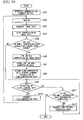
FIG. 3] FIG. 3 is an operation flowchart of an endoscope according to an embodiment of the present invention. - [
FIG. 4] FIG. 4 is an operation flowchart of a display apparatus according to an embodiment of the present invention. - [
FIG 5] FIG 5 is a block diagram of an endoscope according to an embodiment of the present invention. - [
FIG. 6] FIG 6 is a block diagram of a display apparatus according to an embodiment of the present invention. - [
FIG. 7] FIG. 7 is a view showing the packet data transmission timings of a firstwireless transmitting unit 50 and the packet data transmission timings of a secondwireless transmitting unit 53. - [
FIG. 8] FIG. 8 is an operation flowchart of an endoscope according to an embodiment of the present invention. - [
FIG 9] FIG 9 is an operation flowchart of a display apparatus according to an embodiment of the present invention. - [
FIG.10] FIG. 10 is an operation flowchart of a display apparatus according to an embodiment of the present invention. - Next, embodiments of the present invention will be described in detail with reference made to the drawings.
FIG. 1 is a block diagram of an endoscope (i.e., an image transmission terminal) according to the present embodiment. InFIG. 1 , anendoscope 10 is provided with anendoscope operating unit 11, anendoscope power supply 12, anendoscope control unit 13, alight control unit 14, alight source unit 15, alight emitting unit 16, animage capture unit 17, an imagedata generation unit 18, a first imagedata compression unit 19, awireless transmitting unit 20, a second imagedata compression unit 21, and a first imagedata storage unit 22. - The
endoscope operating unit 11 receives operation inputs from a user and outputs operation signals to theendoscope control unit 13 and theendoscope power supply 12. Theendoscope power supply 12 receives a communication connection command from theendoscope operating unit 11 as an operation signal. When theendoscope power supply 12 receives a communication connection command, it begins supplying power to each block of theendoscope 10. Theendoscope power supply 12 also receives a communication disconnection command from theendoscope operating unit 11 as an operation signal. When theendoscope power supply 12 receives a communication disconnection command, it stops supplying power to each block of theendoscope 10 after a predetermined length of time has elapsed since it received the communication disconnection command. Note that the timing at which theendoscope power supply 12 stops supplying power may also be supplied as a command from theendoscope control unit 13. - The
endoscope control unit 13 receives light emission amount data for the light irradiated inside the body cavity as an operation signal from theendoscope operating unit 11, and outputs light emission amount data to thelight control unit 14. When theendoscope control unit 13 receives a communication connection command from theendoscope operating unit 11 as an operation signal, it outputs to the wireless transmitting unit 20 a communication connection command to open communication with thewireless receiving unit 34 of thedisplay apparatus 30 shown inFIG. 2 (described below). When, on the other hand, theendoscope control unit 13 receives a communication disconnection command as an operation signal from theendoscope operating unit 11, it outputs to the wireless transmitting unit 20 a communication disconnection command to close communication with thewireless receiving unit 34 of thedisplay apparatus 30. - The
endoscope control unit 13 receives a low (or non-) compression data generation command (for example, a static image photograph command) from theendoscope operating unit 11 as an operation signal, and outputs a low (or non-) compression data generation command to the second imagedata compression unit 21. Note that theendoscope control unit 13 may also be provided with a storage unit (not shown) for storing parameters used in program operations and the like. - The
image capture unit 17 is provided with a solid state image sensor as typified by, for example, a CCD (Charge Coupled Device) image sensor (referred to below as a CCD), and a CMOS (Complementary Metal Oxide Semiconductor) image sensor (referred to below as a CMOS), and outputs to the imagedata generation unit 18 pixel signals that correspond to the amount of light irradiated onto the solid state image sensor. The imagedata generation unit 18 generates image frame data based on the pixel signals input from theimage capture unit 17, and outputs image frame data to the first imagedata compression unit 19 and the second imagedata compression unit 21. - The first image
data compression unit 19 performs intra-frame compression on the image frame data at a high compression ratio, and outputs the image frame data continuously as moving image data to thewireless transmitting unit 20. - When the
wireless transmitting unit 20 receives a communication connection command from theendoscope control unit 13, it starts packet communication with thewireless receiving unit 34 of thedisplay apparatus 30 shown inFIG 2 (described below). Thewireless transmitting unit 20 also executes modulation processing on the compressed image frame data input from the first imagedata compression unit 19, and transmits packet data for the image frame data as a wireless signal to thewireless receiving unit 34 of thedisplay apparatus 30 shown inFIG. 2 (described below). In contrast, when thewireless transmitting unit 20 receives a communication disconnection command from theendoscope control unit 13, it ends the packet communication with thewireless receiving unit 34 of thedisplay apparatus 30 shown inFIG. 2 (described below). - When the second image
data compression unit 21 receives the low (or non-) compression data generation command from theendoscope control unit 13, it performs intra-frame compression at a low compression ratio on the image frame data, and then outputs the image frame data as static image data to the first imagedata storage unit 22. Here, when the image frame data is being extended, because this image frame data has a high image quality, the compressed image frame data which is output by the second imagedata compression unit 21 is low-compression data that has fewer data losses than the compressed image frame data output by the first imagedata compression unit 19. Note that the second imagedata compression unit 21 may output uncompressed data, or may output lossless compressed data in which absolutely no data loss is generated. - The first image
data storage unit 22 receives compressed image frame data from the second imagedata compression unit 21 and stores this data. Note that the first imagedata storage unit 22 may, for example, be a removable storage medium such as a memory card. The first imagedata storage unit 22 may also be provided with an external interface (not shown), and after converting compressed image frame data into data that conforms to a communication standard for communicating with a peripheral device (not shown) of theendoscope 10, the first imagedata storage unit 22 may output the compressed image frame data to this peripheral device (not shown). - The
light control unit 14 drives thelight source unit 15 based on light emission amount data input from theendoscope control unit 13. Thelight source unit 15 is provided, for example, with a light emitting element such as an LED (Light Emitting Diode). Furthermore, in accordance with the drive signal from thelight control unit 14, thelight source unit 15 supplies light to thelight emitting unit 16 via, for example, an optical fiber. Thelight emitting unit 16 irradiates light supplied in this manner to the interior of a body cavity. -
FIG. 2 is a block diagram of a display apparatus according to the present embodiment. Adisplay apparatus 30 shown inFIG. 2 is provided with a displayapparatus operating unit 31, a displayapparatus power supply 32, a displayapparatus control unit 33, awireless receiving unit 34, an imagedata expansion unit 35, animage processing unit 36, adisplay unit 37, a second imagedata storage unit 38, and anexternal interface 39. - The display
apparatus operating unit 31 receives operation inputs from a user, and outputs operation signals to the displayapparatus control unit 33 and the displayapparatus power supply 32. The displayapparatus power supply 32 receives a communication connection command output from the displayapparatus operating unit 31 as an operation signal. When the displayapparatus power supply 32 receives the communication connection command, this displayapparatus power supply 32 begins supplying power to each block of thedisplay apparatus 30. The displayapparatus power supply 32 also receives a communication disconnection command from the displayapparatus operating unit 31 as an operation signal. When the displayapparatus power supply 32 receives a communication disconnection command, this displayapparatus power supply 32 stops supplying power to each block of thedisplay apparatus 30 after a predetermined length of time has elapsed since it received the communication disconnection command. Note that the timing at which the displayapparatus power supply 32 stops supplying power may also be supplied as a command from the displayapparatus control unit 33. - When the display
apparatus control unit 33 receives a communication connection command from the displayapparatus operating unit 31 as an operation signal, it outputs to the wireless receiving unit 34 a communication connection command to open communication with thewireless transmitting unit 20 of theendoscope 10. When, on the other hand, the displayapparatus control unit 33 receives a communication disconnection command from the displayapparatus operating unit 31 as an operation signal, it outputs to the wireless receiving unit 34 a communication disconnection command to close communication with thewireless transmitting unit 20 of theendoscope 10. - When the
wireless receiving unit 34 receives the communication connection command from the displayapparatus control unit 33, it begins packet communication with thewireless transmitting unit 20 of theendoscope 10. In addition, thewireless receiving unit 34 also executes demodulation processing on the data received as a wireless signal from theendoscope 10, and acquires from the packet data the compressed image frame data transmitted from thewireless transmitting unit 20 of theendoscope 10, and outputs the compressed image frame data to the imagedata expansion unit 35 and the second imagedata storage unit 38. In contrast, when thewireless receiving unit 34 receives a communication disconnection command from the displayunit control unit 33, it ends the packet communication with thewireless transmitting unit 20 of theendoscope 10. - The image
data expansion unit 35 performs expansion processing on the compressed image frame data which is input, and outputs the result to theimage processing unit 36. Theimage processing unit 36 performs image processing such as noise reduction and enhancement processing and the like on the expanded image frame data, and after the image frame data has completed the image processing, theimage processing unit 36 outputs it to thedisplay unit 37. Thedisplay unit 37 displays the image-processed image frame data as images on a display monitor or the like. - The second image
data storage unit 38 stores compressed image frame data which is input from thewireless receiving unit 34. Theexternal interface 39 acquires the compressed image frame data from the second imagedata storage unit 38, and after converting the compressed image frame data into data which conforms to the communication standard for communicating with the peripheral device (not shown) of thedisplay apparatus 30, outputs the compressed image frame data to the peripheral device (not shown). -
FIG 3 is an operation flowchart for the endoscope according to the present embodiment. Theendoscope operating unit 11 receives operation inputs from a user, and outputs operation signals to theendoscope control unit 13 and theendoscope power supply 12. Theendoscope power supply 12 receives a communication connection command from theendoscope operating unit 11 as an operation signal, and begins supplying power to each block of theendoscope 10. - The
endoscope control unit 13 receives light emission amount data for the light irradiated inside the body cavity as an operation signal from theendoscope operating unit 11, and outputs the light emission amount data to thelight control unit 14. Thelight control unit 14 drives thelight source unit 15 based on light emission amount data input from theendoscope control unit 13. Thelight source unit 15 supplies light to thelight emitting unit 16 via, for example, an optical fiber in accordance with the drive signal from thelight control unit 14. Thelight emitting unit 16 irradiates light supplied in this manner to the interior of a body cavity. - The
endoscope control unit 13 receives a communication connection command from theendoscope operating unit 11 as an operation signal, and outputs to the wireless transmitting unit 20 a communication connection command to open communication with thewireless receiving unit 34 of thedisplay apparatus 30. Thewireless transmitting unit 20 receives the communication connection command from theendoscope control unit 13, and begins packet communication with thewireless receiving unit 34 of the display apparatus 30 (step S1). - The
image capture unit 17 to which power is being supplied outputs to the imagedata generation unit 18 pixel signals that correspond to the amount of light irradiated onto the solid state image sensor (step S2). The imagedata generation unit 18 generates image frame data based on the pixel signals input from theimage capture unit 17, and outputs image frame data to the first imagedata compression unit 19 and the second image data compression unit 21 (step S3). The first imagedata compression unit 19 outputs the image frame data that has completed intra-frame compression to the wireless transmitting unit 20 (step S4). - The
endoscope control unit 13 determines whether or not it has received a low (or non-) compression data generation command (for example, a static image photograph command) from the endoscope operating unit 11 (step S5). If theendoscope control unit 13 has not received a low (or non-) compression data generation command (for example, a static image photograph command) from theendoscope operating unit 11 as an operation signal, the routine moves to step S8. - If the
endoscope control unit 13 has received a low (or non-) compression data generation command (for example, a static image photograph command) from theendoscope operating unit 11 as an operation signal, it outputs a low (or non-) compression data generation command to the second imagedata compression unit 21. When the second imagedata compression unit 21 receives the low (or non-) compression data generation command, it outputs to the first imagedata storage unit 22 the image frame data which has undergone intra-frame compression (step S6). The first imagedata storage unit 22 receives the image frame data which has undergone intra-frame compression (i.e., the low (or non-) compression data) from the second imagedata compression unit 21 and stores this data (step S7). - The
wireless transmitting unit 20 executes modulation processing on the compressed image frame data (i.e., high-compression data) input from the first imagedata compression unit 19, and transmits packet data for the image frame data as a wireless signal to thewireless receiving unit 34 of the display apparatus 30 (step S8). When thewireless transmitting unit 20 receives a communication disconnection command, it ends the packet communication with thewireless receiving unit 34 of thedisplay apparatus 30. If, on the other hand, thewireless transmitting unit 20 has not received a communication disconnection command, it returns to step S2. Theendoscope power supply 12 determines whether or not it has received a communication disconnection command from theendoscope operating unit 11 as an operation signal. If theendoscope power supply 12 has received a communication disconnection command, it stops supplying power to each block of theendoscope 10 after a predetermined time has elapsed. If theendoscope power supply 12 has not received a communication disconnection command, it returns to step S2 (step 89). -
FIG 4 is an operation flowchart for the display apparatus according to the present embodiment. The displayapparatus operating unit 31 receives operating input from a user, and outputs operation signals to the displayapparatus control unit 33 and the displayapparatus power supply 32. The displayapparatus power supply 32 receives a communication connection command from the displayapparatus operating unit 31 as an operation signal, and starts supplying power to each block of thedisplay apparatus 30. - The display
apparatus control unit 33 receives the communication connection command from the displayapparatus operating unit 31 as an operation signal, and outputs to the wireless receiving unit 34 a communication connection command instructing it to open communication with thewireless transmitting unit 20 of theendoscope 10. Thewireless receiving unit 34 receives the communication connection command from the displayapparatus control unit 33, and starts packet communication with thewireless transmitting unit 20 of the endoscope 10 (step Sal). - The
wireless receiving unit 34 performs the modulation processing on the data received as a wireless signal, and acquires from the packet data the compressed image frame data (i.e., high-compression data) transmitted from thewireless transmitting unit 20 of theendoscope 10, and outputs this to the imagedata expansion unit 35 and the second image data storage unit 38 (step Sa2). The imagedata expansion unit 35 performs expansion processing on the compressed image frame data (i.e., a high-compression data) which is input, and outputs the result to the image processing unit 36 (step Sa3). Theimage processing unit 36 performs image processing on the expanded image frame data, and outputs the image frame data before the image processing to the display unit 37 (step Sa4). Thedisplay unit 37 displays the image-processed image frame data as images on a display monitor or the like (step Sa5). - When the
wireless receiving unit 34 receives a communication disconnection command, it ends the packet communication with thewireless transmitting unit 20 of theendoscope 10. If, on the other hand, thewireless receiving unit 34 has not received a communication disconnection command, it returns to step Sa2. The displayapparatus power supply 32 determines whether or not it has received a communication disconnection command from the displayapparatus operating unit 31 as an operation signal. If the displayapparatus power supply 32 has received a communication disconnection command, it stops supplying power to each block of thedisplay apparatus 30 after a predetermined time has elapsed. If the displayapparatus power supply 32 has not received a communication disconnection command, it returns to step Sa2 (step Sa6). - If this type of method is employed, because the
wireless transmitting unit 20 of theendoscope 10 does not wirelessly transmit low (or non-) compression data (for example, static image data) which has a large data size, thewireless transmitting unit 20 is able to wirelessly transmit high-compression data (for example, moving image data) to thedisplay apparatus 30 without causing the communication speed to become insufficient. Moreover, because theendoscope 10 stores low (or non-) compression data which has a large data size in the first imagedata storage unit 22 which is provided in theendoscope 10, a user is able to obtain static image data having a high image quality in theendoscope 10. Furthermore, the user is able to display wirelessly transmitted moving image data on thedisplay unit 37 of thedisplay apparatus 30, and is able to obtain moving image data from theexternal interface 39 as well. - Note that it is also possible to employ a structure in which a low (or non-) compression data generation command (for example, a static image capture command) is transmitted from the
wireless transmitting unit 20 of theendoscope 10 to thewireless receiving unit 34 of thedisplay apparatus 30. By employing this structure, thedisplay apparatus 30 which receives the low (or non-) compression data generation command stages a viewing display in which the updating of the image frame data (for example, moving image data) currently displayed on thedisplay unit 37 is temporarily halted. By staging this type of viewing display, theendoscope 10 is able to notify the user that the low (or non-) compression data generation processing has been executed. - Next, a second embodiment of the present invention will be described.
FIG. 5 is a block diagram of an endoscope according to the present embodiment. InFIG. 5 , anendoscope 40 is provided with anendoscope operating unit 41, anendoscope power supply 42, anendoscope control unit 43, alight control unit 44, alight source unit 45, alight emitting unit 46, animage capture unit 47, an imagedata generation unit 48, a first imagedata compression unit 49, a firstwireless transmitting unit 50, a second imagedata compression unit 51, a third imagedata storage unit 52, and a secondwireless transmitting unit 53. - The
endoscope operating unit 41 performs the same type of operations as theendoscope operating unit 11 shown inFIG 1 . Theendoscope power supply 42 performs the same type of operations as theendoscope power supply 12 shown inFIG. 1 . Theendoscope control unit 43 performs the same type of operations as theendoscope control unit 13 shown inFIG 1 . Theendoscope control unit 43 outputs to the first wireless transmitting unit 50 a communication connection command to open communication with the firstwireless receiving unit 64 of thedisplay apparatus 60 shown inFIG 6 (described below). In the same way, theendoscope control unit 43 outputs to the second wireless transmitting unit 53 a communication connection command to open communication with the secondwireless receiving unit 68 of thedisplay apparatus 60 shown inFIG 6 (described below). Theendoscope control unit 43 receives a communication connection command for theendoscope 40 from theendoscope operating unit 41 as an operation signal. Communication disconnection commands are executed by theendoscope control unit 43 operating in the same way as theendoscope control unit 13 shown inFIG. 1 . - The
endoscope control unit 43 issues commands about packet data transmission timings to the firstwireless transmitting unit 50 and the secondwireless transmitting unit 53. Theendoscope control unit 43 also acquires from the firstwireless transmitting unit 50 information showing whether or not the firstwireless transmitting unit 50 has completed the packet data transmission. In the same way, theendoscope control unit 43 acquires from the secondwireless transmitting unit 53 information showing whether or not the secondwireless transmitting unit 53 has completed the packet data transmission. - When the
endoscope control unit 43 has received a low (non-) compression data generation command (for example, a command to photograph a static image) as an operation signal from theendoscope operating unit 41, it outputs the low (non-) compression data generation command to the second imagedata compression unit 51. Furthermore, theendoscope control unit 43 also commands the firstwireless transmitting unit 50 to attach "high-compression data storage command information" to the image frame data. Here, this "high-compression data storage command information" refers to information referenced by the firstwireless receiving unit 64 of thedisplay apparatus 60 in order store image frame data transmitted from the firstwireless transmitting unit 50 in the fourth imagedata storage unit 69 of thedisplay apparatus 60 shown inFIG 6 (described below). Note that this "high-compression data storage command information" is not only information attached to image frame data, but may also be information originally included in the image frame data. Furthermore, it is also possible to switch the bits showing this "high-compression data storage command information" between "valid" and "invalid". - The
endoscope control unit 43 which has received this low (non-) compression data generation command may also command the firstwireless transmitting unit 50 such that the firstwireless transmitting unit 50 temporarily halts the packet data transmission until the packet data transmission of the secondwireless transmitting unit 53 is completed. By doing this, packet data is transmitted to the secondwireless transmitting unit 53 while the packet data transmission performed by the firstwireless transmitting unit 50 is temporarily halted. - The
light control unit 44, thelight source unit 45, and thelight emitting unit 46 perform the same type of operations respectively as thelight control unit 14, thelight source unit 15, and thelight emitting unit 16 inFIG. 1 . Theimage capture unit 47 performs the same type of operations as theimage capture unit 17 inFIG. 1 . The imagedata generation unit 48 performs the same type of operations as the imagedata generation unit 18 inFIG. 1 . - The first image
data compression unit 49 performs the same type of operations as the first imagedata compression unit 19 inFIG 1 . The first imagedata compression unit 49 outputs image frame data (for example, moving image data) that has undergone intra-frame compression to the firstwireless transmitting unit 50. - The first
wireless transmitting unit 50 performs the same type of operations as the firstwireless transmitting unit 20. The firstwireless transmitting unit 50 transmits packet data for the image frame data as a wireless signal to the firstwireless receiving unit 64 of thedisplay apparatus 60 shown inFIG. 6 (described below). Moreover, when the firstwireless transmitting unit 50 receives a command to attach "high-compression data storage command information" from theendoscope control unit 43, it transmits the packet data after attaching the "high-compression data storage command information" to the image frame data. - The second image
data compression unit 51 performs the same type of operations as the second imagedata compression unit 21 inFIG 1 . The second imagedata compression unit 51 outputs to the third imagedata storage unit 52 image frame data (for example, static image data) that has undergone intra-frame compression. Here, because this image frame data is high image quality data, even after the image frame data has been expanded, the compressed image frame data output by the second imagedata compression unit 51 is low-compression data having fewer data losses than the compressed image frame data output by the first imagedata compression unit 49. Note that it is also possible for the second imagedata compression unit 51 to output non-compression data. Alternatively, the second imagedata compression unit 51 may output lossless compressed data in which absolutely no data losses are generated by the expansion processing. - The third image
data storage unit 52 corresponds to the first imagedata storage unit 22 inFIG. 1 , and receives compressed image frame data from the second imagedata compression unit 51 and stores it. The third imagedata storage unit 52 also outputs compressed image frame data to the secondwireless transmitting unit 53. - When the second
wireless transmitting unit 53 received a communication connection command from theendoscope control unit 43, it starts packet communication with the secondwireless receiving unit 68 of thedisplay apparatus 60 shown inFIG. 6 (described below). The secondwireless transmitting unit 53 also transmits data packets of the image frame data as a wireless signal to the secondwireless receiving unit 68 of thedisplay apparatus 60 shown inFIG. 6 (described below). On the other hand, when the secondwireless transmitting unit 53 receives a communication disconnection command from theendoscope control unit 43, it ends the packet communication with the secondwireless receiving unit 68 of thedisplay apparatus 60 shown inFIG 6 (described below). - Note that it is not necessary for the second
wireless transmitting unit 53 to employ the same communication system as the firstwireless transmitting unit 50, and it is also possible for it to execute faster communication than the firstwireless transmitting unit 50. For example, it is also possible for the secondwireless transmitting unit 53 to perform multi-value modulation in which a large quantity of information is delivered in one segment (symbol) of a signal. It is also possible for the secondwireless transmitting unit 53 to have a wider communication bandwidth than the firstwireless transmitting unit 50. -
FIG. 6 is a block diagram of a display apparatus according to the present embodiment. Adisplay apparatus 60 shown inFIG. 6 is provided with a displayapparatus operating unit 61, a displayapparatus power supply 62, a displayapparatus control unit 63, a firstwireless receiving unit 64, an imagedata expansion unit 65, animage processing unit 66, adisplay unit 67, a secondwireless receiving unit 68, a fourth imagedata storage unit 69, and anexternal interface 70. - The display
apparatus operating unit 61 performs the same type of operations as the displayapparatus operating unit 31 inFIG 2 . The displayapparatus power supply 62 performs the same type of operations as the displayapparatus power supply 32 inFIG. 1 . The displayapparatus control unit 63 performs the same type of operations as the displayapparatus control unit 33 inFIG. 2 . The displayapparatus control unit 63 receives a communication connection command as an operation signal from the displayapparatus operating unit 61, and outputs to the first wireless receiving unit 64 a communication connection command to open communication with the firstwireless transmitting unit 50 of theendoscope 40. In the same way, the displayapparatus control unit 63 outputs to the second wireless receiving unit 68 a communication connection command to open communication with the secondwireless transmitting unit 53 of theendoscope 40. Communication disconnection commands are executed by the displayapparatus control unit 63 operating in the same way as theendoscope control unit 33 shown inFIG 2 . - The first
wireless receiving unit 64 receives a communication connection command from the displayapparatus control unit 63, and starts packet communication with the firstwireless transmitting unit 50 of theendoscope 40. The firstwireless receiving unit 64 performs demodulation processing on the data received as a wireless signal, and acquires compressed image frame data transmitted from the firstwireless transmitting unit 50 of theendoscope 40 from the packet data, and then outputs this to the imagedata expansion unit 65. - The first
wireless receiving unit 64 detects whether or not "high-compression data storage command information" is attached to the image frame data (i.e., high-compression data) transmitted from the firstwireless transmitting unit 50 inFIG. 5 . If this "high-compression data storage command information" is attached, the firstwireless receiving unit 64 outputs the compressed image frame data to the fourth imagedata storage unit 69 as well. - The second
wireless receiving unit 68 receives a communication connection command from the displayapparatus control unit 63, and starts packet communication with the secondwireless transmitting unit 53 of theendoscope 40. The secondwireless receiving unit 68 executes demodulation processing on the data received as a wireless signal, and acquires compressed image frame data transmitted from the secondwireless transmitting unit 53 of theendoscope 40 from the packet data, and then outputs this to the fourth imagedata storage unit 69. - The image
data expansion unit 65 performs expansion processing on the compressed image frame data which is input into it, and then outputs the results to theimage processing unit 66. Theimage processing unit 66 performs image processing such as noise reduction and enhancement processing and the like on the expanded image frame data, and after the image frame data has completed the image processing, theimage processing unit 66 outputs it to thedisplay unit 67. Thedisplay unit 67 displays the image-processed image frame data as images on a display monitor or the like. - The fourth image
data storage unit 69 stores compressed image frame data which is input into it. Note that the fourth imagedata storage unit 69 may also be a removable storage medium as typified, for example, by memory cards. Theexternal interface 70 acquires the compressed image frame data from the fourth imagedata storage unit 69, and after converting it into data which conforms to the communication standard for communicating with the peripheral device (not shown) of thedisplay apparatus 60, outputs the compressed image frame data to the peripheral device (not shown). -
FIG. 7 shows the packet data transmission timings of the firstwireless transmitting unit 50 and the packet data transmission timings of the secondwireless transmitting unit 53. The firstwireless transmitting unit 50 transmits high-compression data packets (for example, moving image data). The secondwireless transmitting unit 53 transmits low (or non-) compression data packets (for example, static image data). Here, it is also possible for theendoscope control unit 43 to decide transmission blank periods, which are periods during which the firstwireless transmitting unit 50 is not transmitting packet data, for example, by determining whether or not the image frame data transmission is fully completed. Alternatively, these transmission blank periods may also be decided by the packet data being transmitted at a predetermined cycle. Note that it is also possible for the firstwireless transmitting unit 50 and the secondwireless transmitting unit 53 to transmit packet data alternatingly at a predetermined cycle regardless of whether they have received commands from theendoscope control unit 43. -
FIG. 8 is an operation flowchart of the endoscope according to the present embodiment. Theendoscope operating unit 41 receives operation inputs from a user, and outputs operation signals to theendoscope control unit 43 and theendoscope power supply 42. Theendoscope power supply 42 receives a communication connection command from theendoscope operating unit 41 as an operation signal, and begins supplying power to each block of theendoscope 40. - The
endoscope control unit 43 receives light emission amount data for the light irradiated inside the body cavity as an operation signal from theendoscope operating unit 41, and outputs the light emission amount data to thelight control unit 44. Thelight control unit 44 drives thelight source unit 45 based on light emission amount data input from theendoscope control unit 43. Thelight source unit 45 supplies light to thelight emitting unit 46 via, for example, an optical fiber in accordance with the drive signal from thelight control unit 44. Thelight emitting unit 46 irradiates light supplied in this manner to the interior of a body cavity. - The
endoscope control unit 43 receives a communication connection command from theendoscope operating unit 41 as an operation signal. Theendoscope control unit 43 outputs to the first wireless transmitting unit 50 a communication connection command to open communication with the firstwireless receiving unit 64 of thedisplay apparatus 60. The firstwireless transmitting unit 50 receives the communication connection command from theendoscope control unit 43, and begins packet communication with the firstwireless receiving unit 64 of thedisplay apparatus 60. In the same way, the secondwireless transmitting unit 53 begins packet communication with the secondwireless receiving unit 68 of the display apparatus 60 (step Sb1). - The routine from step Sb2 to step Sb3 is the same as the routine from step S2 to step S3 in
FIG. 3 . The first imagedata compression unit 49 outputs to the firstwireless transmitting unit 50 the image frame data that has completed intra-frame compression (step Sb4). - The
endoscope control unit 43 determines whether or not a low (or non-) compression data generation command has been received from the endoscope operating unit 41 (step Sb5). If theendoscope control unit 43 has received a low (or non-) compression data generation command (for example, a static image capture command) as an operation signal from theendoscope operating section 41, it outputs the low (or non-) compression data generation command to the second imagedata compression unit 51. Furthermore, theendoscope control unit 43 also commands the firstwireless transmitting unit 50 to attach "high-compression data storage command information" to the image frame data (i.e., high-compression data) output by the first imagedata compression unit 49. If a low (or non-) compression data generation command has not been received as an operation signal from theendoscope operating section 41, theendoscope control unit 43 moves to step Sb9. - When the second image
data compression unit 51 receives the low (or non-) compression data generation command, it outputs the compressed image frame data to the third image data storage unit 52 (step Sb6). The third imagedata storage unit 52 receives the compressed image frame data from the second imagedata compression unit 51 and stores this data (step Sb7). The firstwireless transmitting unit 50 which was commanded to attach the "high-compression data storage command information" attaches the "high-compression data storage commands information" to the high-compression data (step Sb8). - Next, the
endoscope control unit 43 determines whether or not there is currently a transmission blank period in accordance with the aforementioned conditions (step Sb9). If it is not determined to be a transmission blank period, theendoscope control unit 43 commands the firstwireless transmitting unit 50 to transmit packet data. The firstwireless transmitting unit 50 then transmits data packets of the image frame data (i.e., high-compression data) as a wireless signal to the firstwireless receiving unit 64 of the display apparatus 60 (step Sb10). - When the first
wireless transmitting unit 50 and the secondwireless transmitting unit 53 receive a communication disconnection commands, they end packet communication with the respective wireless receiving units of thedisplay apparatus 60. In contrast, if they have not received a communication disconnection command, the firstwireless transmitting unit 50 and the secondwireless transmitting unit 53 return to step Sb2. Theendoscope power supply 42 also determines whether or not a communication disconnection command has been received as an operation signal from theendoscope operating unit 41. If a communication disconnection command has been received, theendoscope power supply 42 stops supplying power to each block of theendoscope 40 after a predetermined time has elapsed. If a communication disconnection command has not been received, theendoscope power supply 42 returns to step Sb2 (Step Sb11). - If it is determined in step Sb9 to be a transmission blank period, the
endoscope control unit 43 determines whether or not the packet data transmission by the secondwireless transmitting unit 53 was completed during the previous attempt. If the transmission was completed, the routine returns to step Sb11 (step Sb12). If the transmission was not completed, theendoscope control unit 43 commands the secondwireless transmitting unit 53 to transmit packet data. The secondwireless transmitting unit 53 then transmits data packets of the image frame data (i.e., low (or un-) compressed data) as a wireless signal to the secondwireless receiving unit 68, and the routine moves to step Sb9 (step Sb13). -
FIG 9 is an operation flowchart for the display apparatus according to the present embodiment. The displayapparatus operating unit 61 receives operating input from a user, and outputs operation signals to the displayapparatus control unit 63 and the displayapparatus power supply 62. The displayapparatus power supply 62 receives a communication connection command from the displayapparatus operating unit 61 as an operation signal, and starts supplying power to each block of thedisplay apparatus 60. - The display
apparatus control unit 63 receives the communication connection command from the displayapparatus operating unit 61 as an operation signal, and outputs to the first wireless receiving unit 64 a communication connection command instructing it to open communication with thewireless transmitting unit 50 of theendoscope 40. The firstwireless receiving unit 64 receives the communication connection command from the displayapparatus control unit 63, and starts packet communication with the firstwireless transmitting unit 50 of theendoscope 40. In the same way, the secondwireless receiving unit 68 receives the communication connection command from the displayapparatus control unit 63, and starts packet communication with the secondwireless transmitting unit 53 of the endoscope 40 (step Sc1). - If a packet data transmission has been made from the first
wireless transmitting unit 50, the firstwireless receiving unit 64 executes demodulation processing on the received data, and acquires the packet data from the compressed image frame data, and then outputs it to the image data expansion unit 65 (step Sc2). In step Sc3, if a transmission of packet data has been made from the secondwireless transmitting unit 53, the secondwireless receiving unit 68 executes demodulation processing on the received data, and acquires the packet data from the compressed image frame data, and then outputs it to the imagedata expansion unit 65 and the fourth imagedata storage unit 69. The fourth imagedata storage unit 69 stores the compressed image frame data (i.e., low (or un-) compressed data) (step Sc4). - The image
data expansion unit 65 performs expansion processing using a plurality of packets of packet data. Accordingly, even if packet data was not received in step Sc2, the imagedata expansion unit 65 executes expansion processing on the compressed image frame data that has been input up until the previous time (step Sc5). Theimage processing unit 66 executes image processing on the expanded image frame data, and outputs the image frame data which has completed image processing to the display unit 67 (step Sc6). - The first
wireless receiving unit 64 detects whether or not "high-compression data storage command information" is attached to the image frame data in the received packet data (step Sc7). If this "high-compression data storage command information" is attached, the firstwireless receiving unit 64 outputs the compressed image frame data to the fourth imagedata storage unit 69. The fourth imagedata storage unit 69 stores the compressed image frame data (step Sc8). - The
display unit 67 displays the image-processed image frame data as images on a display monitor or the like (step Sc9). When the firstwireless receiving unit 64 and the secondwireless receiving unit 68 receive a communication disconnection command, they end the packet communication with the respective wireless transmitting units of theendoscope 40. If, on the other hand, the firstwireless receiving unit 64 and the secondwireless receiving unit 68 have not received a communication disconnection command, they return to step Sc2. The displayapparatus power supply 62 determines whether or not it has received a communication disconnection command from the displayapparatus operating unit 61 as an operation signal. If the displayapparatus power supply 62 has received a communication disconnection command, it stops supplying power to each block of thedisplay apparatus 60 after a predetermined time has elapsed. If the displayapparatus power supply 62 has not received a communication disconnection command, it returns to step Sc2 (step Sc10). - If this type of method is employed, the second
wireless transmitting unit 53 of theendoscope 40 is able to wirelessly transmit low (or non-) compression data (for example, static image data) which has a large data size during blank periods of high-compression data (for example, moving image data) transmission. Namely, the firstwireless transmitting unit 50 is able to wirelessly transmit high-compression data to thedisplay apparatus 60 without causing the communication speed to become insufficient. As a result, the user is able to obtain static image data having a high image quality from the fourth imagedata storage unit 69 and theexternal interface 70 of thedisplay apparatus 60. - Note that the timings of the low (or non-) compression data (for example, static image data) transmissions may also be set in the following manner.
FIG. 10 is an operation flowchart of the display apparatus according to the present embodiment. Here, step Sd1 through step Sd8 are the same as step Sb1 through step Sb8 inFIG 8 . - When a user wishes to end an examination being performed with the
endoscope 40, theendoscope operating unit 41 receives a stop command for the light control unit 44 (i.e., a command to turn off the light emitting unit 46), and notifies theendoscope control unit 43 about the stop command for thelight control unit 44. Theendoscope control unit 43 determines whether or not it has received a stop command for thelight control unit 44 from the endoscope operating unit 41 (step Sd9). If theendoscope control unit 43 has not received the stop command for thelight control unit 44, then because it assumes that the user is continuing the examination performed with theendoscope 40, theendoscope control unit 43 commands the firstwireless transmitting unit 50 to transmit data packets of the image frame data (i.e., high-compression data). The firstwireless transmitting unit 50 transmits data packets of the image frame data (i.e., a high-compression data) as a wireless signal to the firstwireless receiving unit 64 of thedisplay apparatus 60, and then moves to step Sd2 (step Sd10). - When the
endoscope control unit 43 has received a stop command for thelight control unit 44, then because it assumes that the user is ending the examination performed with theendoscope 40, theendoscope control unit 43 receives the stop command for thelight control unit 44 and stops operations of thelight control unit 44.
In addition, theendoscope control unit 43 commands the firstwireless transmitting unit 50 to stop transmitting image frame data. Furthermore, theendoscope control unit 43 determines whether or not the secondwireless transmitting unit 53 has completed the transmission of the entire group of data packets. If the transmission has not been completed, theendoscope control unit 43 commands the secondwireless transmitting unit 53 to transmit the un-transmitted packet data. When the secondwireless transmitting unit 53 receives the packet data transmission command, it transmits the data packets of image frame data (i.e., low (or un-) compressed data) as a wireless signal to the secondwireless receiving unit 68 of thedisplay apparatus 60, and then moves to step Sd9 (step Sd12). - If this type of method is employed, because the second
wireless transmitting unit 53 of theendoscope 40 wirelessly transmits low (or non-) compression data (for example, static image data) which has a large data size collectively after the transmission of the high-compression data (for example, moving image data) has been stopped, the firstwireless transmitting unit 50 is able to wirelessly transmit high-compression data to thedisplay apparatus 60 without causing the communication speed to become insufficient. As a result, the user is able to obtain static image data having a high image quality from the fourth imagedata storage unit 69 and theexternal interface 70 of thedisplay apparatus 60. - Note that for the determination conditions of step Sd9 in
FIG. 10 , instead of determining whether or not a stop command for thelight control unit 44 has been received, it is also possible to determine whether or not a communication disconnection command has been made to theendoscope power supply 42, namely, whether theendoscope power supply 42 has received a command to stop supplying power to theendoscope 40. Furthermore, if the power held by theendoscope power supply 42 is insufficient, then it is also possible for theendoscope 40 to wait until theendoscope power supply 42 has been recharged, and to then use the next power supply command as a trigger for collectively transmitting data packets to thedisplay apparatus 60. - Embodiments of this invention have been described above in detail with reference made to the drawings. However, the specific structure thereof is not limited to these embodiments, and various design modifications and the like are included therein insofar as they do not depart from the spirit or scope of this invention.
- Moreover, the image capture unit described in the present invention corresponds to the
image capture unit 17 and theimage capture unit 47. The image data generation unit corresponds to the imagedata generation unit 18 and the imagedata generation unit 48. The first image data compression unit corresponds to the first imagedata compression unit 19 and the first imagedata compression unit 49. The second image data compression unit corresponds to the second imagedata compression unit 21 and the second imagedata compression unit 51. The image data storage unit corresponds to the first imagedata storage unit 22 and the third imagedata storage unit 52. The image transmission unit corresponds to thewireless transmitting unit 20, the firstwireless transmitting unit 50, and the secondwireless transmitting unit 38. The operating unit corresponds to theendoscope operating unit 11 and theendoscope operating unit 41. The image selection unit corresponds to theendoscope operating unit 11, theendoscope control unit 13, theendoscope operating unit 41, and theendoscope control unit 43. - It is also possible for a program which achieves the respective steps shown in
FIG. 3 ,FIG 4 ,FIG. 8 ,FIG. 9 , andFIG 10 to be recorded on a computer-readable recording medium. It is also possible for the processing executed by the communication terminal to be performed by causing this program recorded on a recording medium to be read and executed by a computer system. Note that, here, the term 'computer system' may include the OS (Operating System) and hardware such as peripheral devices and the like. - Moreover, if a WWW system is being utilized, then 'computer system' can also include a homepage provider environment (or display environment). Moreover, 'Computer readable recording medium' refers to a flexible disk, an electro-optic disk, ROM, recordable non-volatile memory such as flash memory, transportable media such as a CD-ROM and the like, and recording devices such as hard disks that are built into a computer system.
- Moreover, 'Computer readable recording medium' also includes devices that hold a program for a fixed time such as the internal volatile memory (for example, DRAM (Dynamic random Access Memory)) in a computer system which forms the server or client when the program is transmitted via a network such as the Internet or via a communication line such as a telephone line.
Moreover, this program may also be transmitted from a computer system that stores the program on a storage device or the like via a transmission medium. Alternatively, this program may be transmitted to another computer system by means of a transmission wave within the transmission medium. Here, the 'transmission medium' which transmits the program refers to a medium having a function of transmitting information such as a network such as the Internet or a communication line such as a telephone line.
Moreover, the above described program may also be designed to fulfill a portion of the above described functions. Furthermore, the above described program may also achieve these functions in combination with a program which is already recorded on the computer system. The above described program may also be what is known as a differential file (i.e., a differential program). - According to the present invention, an image transmission terminal stores static image data that has a large data size in the image transmission terminal without wirelessly transmitting this data. As a result, a user is able to obtain static image data having a high image quality in an image transmission terminal. In addition, as a result of the image transmission terminal wirelessly transmitting the static image data having a large data size during blank periods of the moving image transmission, a user is able to obtain static image data having a high image quality on a display apparatus. Namely, the present invention makes it possible to achieve a superior image transmission terminal in order to wirelessly transmit image data.
- 10 ...
Endoscope 11 ...Endoscope operating unit 12 ...Endoscope power supply 13 ...Endoscope control unit 14 ...Light control unit 15 ...Light source unit 16 ...Light emitting unit 17 ...Image capture unit 18 ... Imagedata generation unit 19 ... First imagedata compression unit 20 ...Wireless transmitting unit 21 ... Second imagedata compression unit 22 ... First imagedata storage unit 30 ...Display apparatus 31 ... Displayapparatus operating unit 32 ... Displayapparatus power supply 33 ... Displayapparatus control unit 34 ...Wireless receiving unit 35 ... Imagedata expansion unit 36 ...Image processing unit 37 ...Display unit 38 ... Second imagedata storage unit 39 ...External interface 40 ...Endoscope 41 ...Endoscope operating unit 42 ...Endoscope power supply 43 ...Endoscope control unit 44 ...Light control unit 45 ...Light source unit 46 ...Light emitting unit 47 ...Image capture unit 48 ... Imagedata generation unit 49 ... First imagedata compression unit 50 ... Firstwireless transmitting unit 51 ... Second imagedata compression unit 52 ... Third imagedata storage unit 53 ... Secondwireless transmitting unit 60 ...Display apparatus 61 ... Displayapparatus operating unit 62 ... Displayapparatus power supply 63 ... Displayapparatus control unit 64 ... Firstwireless receiving unit 65 ... Imagedata expansion unit 66 ...Image processing unit 67 ...Display unit 68 ... Secondwireless receiving unit 69 ... Fourth imagedata storage unit 70 ... External interface
Claims (6)
- An image transmission terminal comprising:an image capture unit that outputs pixel signals that correspond to an amount of light irradiated onto an imaging element;an image data generating unit that generates and then outputs image frame data based on the pixel signals;a first image data compression unit that compresses the image frame data at a predetermined compression rate and then outputs the image frame data;a second image data compression unit that either leaves the image frame data uncompressed or compresses the image frame data at a lower compression rate than the predetermined compression rate and then outputs the image frame data;an image selection unit that receives an operation input from a user, and that, based on the operation input, selects the image frame data captured by the image capture unit;an image data storage unit that, in accordance with the selection made by the image selection unit, stores the image frame data output from the second image data compression unit; andan image transmission unit that wirelessly transmits the image frame data output from the first image data compression unit.
- The image transmission terminal according to claim 1, wherein
there is provided an operating unit that receives a communication disconnection command operation performed by a user, and outputs an operation signal based on this operation, and
the image transmission unit wirelessly transmits the image frame data stored in the image data storage unit when it receives the operation signal. - The image transmission terminal according to claim 1, wherein
when the image selection unit selects the image frame data, it interrupts the wireless transmission of the image frame data output from the first image data compression unit, and wirelessly transmits the image frame data stored in the image data storage unit. - The image transmission terminal according to claim 1, wherein
the image data storage unit is a removable storage medium. - The image transmission terminal according to claim 1, wherein
the image data storage unit is provided with an external interface. - The image communication terminal according to claim 1, wherein
the image transmission terminal wirelessly transmits the image frame data stored in the image data storage unit during a period when a wireless transmission of the image frame data output from the first image data compression unit has stopped.
Applications Claiming Priority (2)
| Application Number | Priority Date | Filing Date | Title |
|---|---|---|---|
| JP2009097012A JP5489516B2 (en) | 2009-04-13 | 2009-04-13 | Image transmission terminal, image transmission method, and program |
| PCT/JP2010/002567 WO2010119648A1 (en) | 2009-04-13 | 2010-04-08 | Image transmission terminal |
Publications (3)
| Publication Number | Publication Date |
|---|---|
| EP2421244A1 true EP2421244A1 (en) | 2012-02-22 |
| EP2421244A4 EP2421244A4 (en) | 2013-01-02 |
| EP2421244B1 EP2421244B1 (en) | 2019-07-17 |
Family
ID=42982323
Family Applications (1)
| Application Number | Title | Priority Date | Filing Date |
|---|---|---|---|
| EP10764235.7A Active EP2421244B1 (en) | 2009-04-13 | 2010-04-08 | Endoscope for wireless image data transmission |
Country Status (5)
| Country | Link |
|---|---|
| US (1) | US8553996B2 (en) |
| EP (1) | EP2421244B1 (en) |
| JP (1) | JP5489516B2 (en) |
| CN (1) | CN102387738B (en) |
| WO (1) | WO2010119648A1 (en) |
Cited By (1)
| Publication number | Priority date | Publication date | Assignee | Title |
|---|---|---|---|---|
| EP2445210A1 (en) * | 2009-06-15 | 2012-04-25 | Olympus Corporation | Image transmission device and image reception device |
Families Citing this family (7)
| Publication number | Priority date | Publication date | Assignee | Title |
|---|---|---|---|---|
| JP5864876B2 (en) * | 2011-03-25 | 2016-02-17 | オリンパス株式会社 | Image processing apparatus and image processing method |
| US10104331B2 (en) * | 2012-12-31 | 2018-10-16 | Karl Storz Imaging, Inc. | Camera control unit with stereoscopic video recording and archive |
| US9841280B2 (en) | 2012-12-31 | 2017-12-12 | Karl Storz Imaging, Inc. | Modular medical imaging system |
| JP6092049B2 (en) * | 2013-08-28 | 2017-03-08 | 東芝ライフスタイル株式会社 | Imaging system and imaging apparatus |
| JP6423172B2 (en) | 2014-05-22 | 2018-11-14 | オリンパス株式会社 | Wireless endoscope system, display device, and program |
| DE112015006470T5 (en) * | 2015-05-15 | 2018-01-04 | Olympus Corporation | Apparatus for sending compressed image data, system for sending and receiving compressed image data, method for sending compressed image data and program |
| JP6744876B2 (en) * | 2016-01-25 | 2020-08-19 | オリンパス株式会社 | Image transmitting device, image communication system, image transmitting method, and program |
Citations (4)
| Publication number | Priority date | Publication date | Assignee | Title |
|---|---|---|---|---|
| EP0979009A2 (en) * | 1998-08-05 | 2000-02-09 | Matsushita Electronics Corporation | Surveillance and remote surveillance camera, apparatus and system |
| US20070216781A1 (en) * | 2006-02-24 | 2007-09-20 | Olympus Corporation | Image pickup apparatus |
| EP2445210A1 (en) * | 2009-06-15 | 2012-04-25 | Olympus Corporation | Image transmission device and image reception device |
| EP2478824A1 (en) * | 2009-10-21 | 2012-07-25 | Olympus Corporation | Endoscope and wireless endoscope system |
Family Cites Families (9)
| Publication number | Priority date | Publication date | Assignee | Title |
|---|---|---|---|---|
| JPH06335450A (en) | 1993-05-31 | 1994-12-06 | Olympus Optical Co Ltd | Electronic endscope equipment |
| JPH10294939A (en) * | 1997-04-22 | 1998-11-04 | Canon Inc | System and device for image transmission |
| US20040030929A1 (en) * | 2001-11-06 | 2004-02-12 | Depeng Bi | Digital audio and video distribution transmission and playback |
| JP2003169291A (en) * | 2001-11-30 | 2003-06-13 | Canon Inc | Electronic device, data transmission method, computer- readable storage medium, and computer program |
| JP3984080B2 (en) * | 2002-03-13 | 2007-09-26 | ペンタックス株式会社 | Network camera system |
| JP4195625B2 (en) * | 2002-03-13 | 2008-12-10 | Hoya株式会社 | Camera adapter device |
| JP4009581B2 (en) * | 2003-11-18 | 2007-11-14 | オリンパス株式会社 | Capsule medical system |
| JP4890880B2 (en) * | 2006-02-16 | 2012-03-07 | キヤノン株式会社 | Image transmitting apparatus, image transmitting method, program, and storage medium |
| JP5300395B2 (en) | 2007-09-28 | 2013-09-25 | ユニチカ株式会社 | Polyester resin composition, fiber obtained from the resin composition, and method for producing the fiber |
-
2009
- 2009-04-13 JP JP2009097012A patent/JP5489516B2/en not_active Expired - Fee Related
-
2010
- 2010-04-08 WO PCT/JP2010/002567 patent/WO2010119648A1/en active Application Filing
- 2010-04-08 CN CN201080016095.6A patent/CN102387738B/en not_active Expired - Fee Related
- 2010-04-08 EP EP10764235.7A patent/EP2421244B1/en active Active
-
2011
- 2011-10-12 US US13/271,787 patent/US8553996B2/en active Active
Patent Citations (4)
| Publication number | Priority date | Publication date | Assignee | Title |
|---|---|---|---|---|
| EP0979009A2 (en) * | 1998-08-05 | 2000-02-09 | Matsushita Electronics Corporation | Surveillance and remote surveillance camera, apparatus and system |
| US20070216781A1 (en) * | 2006-02-24 | 2007-09-20 | Olympus Corporation | Image pickup apparatus |
| EP2445210A1 (en) * | 2009-06-15 | 2012-04-25 | Olympus Corporation | Image transmission device and image reception device |
| EP2478824A1 (en) * | 2009-10-21 | 2012-07-25 | Olympus Corporation | Endoscope and wireless endoscope system |
Non-Patent Citations (1)
| Title |
|---|
| See also references of WO2010119648A1 * |
Cited By (3)
| Publication number | Priority date | Publication date | Assignee | Title |
|---|---|---|---|---|
| EP2445210A1 (en) * | 2009-06-15 | 2012-04-25 | Olympus Corporation | Image transmission device and image reception device |
| EP2445210A4 (en) * | 2009-06-15 | 2013-02-20 | Olympus Corp | Image transmission device and image reception device |
| US8908756B2 (en) | 2009-06-15 | 2014-12-09 | Olympus Corporation | Image transmission apparatus and image reception apparatus |
Also Published As
| Publication number | Publication date |
|---|---|
| CN102387738B (en) | 2016-02-24 |
| US20120082390A1 (en) | 2012-04-05 |
| CN102387738A (en) | 2012-03-21 |
| US8553996B2 (en) | 2013-10-08 |
| EP2421244B1 (en) | 2019-07-17 |
| EP2421244A4 (en) | 2013-01-02 |
| JP5489516B2 (en) | 2014-05-14 |
| WO2010119648A1 (en) | 2010-10-21 |
| JP2010251902A (en) | 2010-11-04 |
Similar Documents
| Publication | Publication Date | Title |
|---|---|---|
| EP2421244A1 (en) | Image transmission terminal | |
| JP5364459B2 (en) | Image transmitting apparatus, image receiving apparatus, image transmitting method, image receiving method, and program | |
| JP5622350B2 (en) | Intra-subject introduction apparatus and intra-subject information acquisition system | |
| US20080091065A1 (en) | Medical image processing apparatus, endoscope system and medical image processing system | |
| JP2013529950A (en) | In vivo camera image acquisition control | |
| JP2006325150A (en) | Method, system and apparatus for imaging | |
| JP4709573B2 (en) | Electronic endoscope device | |
| US20060038888A1 (en) | Image transmission apparatus | |
| EP1870013A1 (en) | Image display device | |
| US10390017B2 (en) | Compressed image data transmitting device, compressed image data transmitting and receiving system, compressed image data transmitting method, and non-transitory medium saving program | |
| US20230172426A1 (en) | Medical system, processing protocol control method, and signal processing device | |
| KR20110068863A (en) | Image processing system, image processing apparatus, image pickup apparatus, method, and computer-readable medium | |
| JP2006080860A (en) | Camera and camera image transfer system | |
| JP2004312433A (en) | Image processing system | |
| JP5816469B2 (en) | Biological information acquisition system and method of operating biological information acquisition system | |
| JP2012161541A (en) | Medical image processing device and electronic endoscope system | |
| JP2007329946A (en) | Capsule endoscope system | |
| JP2016032282A (en) | Electronic equipment and control method of the same | |
| US20070041630A1 (en) | Imaging module and data receiving apparatus | |
| WO2017033617A1 (en) | Moving image transmission and reception system | |
| JP2006075365A (en) | Receiver apparatus and subject internal guiding system | |
| JP2006129191A (en) | Image compressing device | |
| JP2008011540A (en) | Capsule endoscope system | |
| JP2007243753A (en) | Image recorder |
Legal Events
| Date | Code | Title | Description |
|---|---|---|---|
| PUAI | Public reference made under article 153(3) epc to a published international application that has entered the european phase |
Free format text: ORIGINAL CODE: 0009012 |
|
| 17P | Request for examination filed |
Effective date: 20111019 |
|
| AK | Designated contracting states |
Kind code of ref document: A1 Designated state(s): AT BE BG CH CY CZ DE DK EE ES FI FR GB GR HR HU IE IS IT LI LT LU LV MC MK MT NL NO PL PT RO SE SI SK SM TR |
|
| DAX | Request for extension of the european patent (deleted) | ||
| A4 | Supplementary search report drawn up and despatched |
Effective date: 20121130 |
|
| RIC1 | Information provided on ipc code assigned before grant |
Ipc: H04N 7/173 20110101ALI20121126BHEP Ipc: A61B 1/00 20060101ALI20121126BHEP Ipc: H04N 5/225 20060101AFI20121126BHEP Ipc: H04N 7/18 20060101ALI20121126BHEP |
|
| RAP1 | Party data changed (applicant data changed or rights of an application transferred) |
Owner name: OLYMPUS CORPORATION |
|
| RAP1 | Party data changed (applicant data changed or rights of an application transferred) |
Owner name: OLYMPUS CORPORATION |
|
| RAP1 | Party data changed (applicant data changed or rights of an application transferred) |
Owner name: OLYMPUS CORPORATION |
|
| RIN1 | Information on inventor provided before grant (corrected) |
Inventor name: HONDA, TAKEMITSU Inventor name: KAWASAKI, SHINYA |
|
| STAA | Information on the status of an ep patent application or granted ep patent |
Free format text: STATUS: EXAMINATION IS IN PROGRESS |
|
| 17Q | First examination report despatched |
Effective date: 20170210 |
|
| GRAP | Despatch of communication of intention to grant a patent |
Free format text: ORIGINAL CODE: EPIDOSNIGR1 |
|
| STAA | Information on the status of an ep patent application or granted ep patent |
Free format text: STATUS: GRANT OF PATENT IS INTENDED |
|
| INTG | Intention to grant announced |
Effective date: 20190222 |
|
| GRAS | Grant fee paid |
Free format text: ORIGINAL CODE: EPIDOSNIGR3 |
|
| GRAA | (expected) grant |
Free format text: ORIGINAL CODE: 0009210 |
|
| STAA | Information on the status of an ep patent application or granted ep patent |
Free format text: STATUS: THE PATENT HAS BEEN GRANTED |
|
| AK | Designated contracting states |
Kind code of ref document: B1 Designated state(s): AT BE BG CH CY CZ DE DK EE ES FI FR GB GR HR HU IE IS IT LI LT LU LV MC MK MT NL NO PL PT RO SE SI SK SM TR |
|
| REG | Reference to a national code |
Ref country code: GB Ref legal event code: FG4D |
|
| REG | Reference to a national code |
Ref country code: CH Ref legal event code: EP |
|
| REG | Reference to a national code |
Ref country code: IE Ref legal event code: FG4D |
|
| REG | Reference to a national code |
Ref country code: DE Ref legal event code: R096 Ref document number: 602010060049 Country of ref document: DE |
|
| REG | Reference to a national code |
Ref country code: AT Ref legal event code: REF Ref document number: 1156897 Country of ref document: AT Kind code of ref document: T Effective date: 20190815 |
|
| REG | Reference to a national code |
Ref country code: NL Ref legal event code: MP Effective date: 20190717 |
|
| REG | Reference to a national code |
Ref country code: LT Ref legal event code: MG4D |
|
| REG | Reference to a national code |
Ref country code: AT Ref legal event code: MK05 Ref document number: 1156897 Country of ref document: AT Kind code of ref document: T Effective date: 20190717 |
|
| PG25 | Lapsed in a contracting state [announced via postgrant information from national office to epo] |
Ref country code: FI Free format text: LAPSE BECAUSE OF FAILURE TO SUBMIT A TRANSLATION OF THE DESCRIPTION OR TO PAY THE FEE WITHIN THE PRESCRIBED TIME-LIMIT Effective date: 20190717 Ref country code: LT Free format text: LAPSE BECAUSE OF FAILURE TO SUBMIT A TRANSLATION OF THE DESCRIPTION OR TO PAY THE FEE WITHIN THE PRESCRIBED TIME-LIMIT Effective date: 20190717 Ref country code: NL Free format text: LAPSE BECAUSE OF FAILURE TO SUBMIT A TRANSLATION OF THE DESCRIPTION OR TO PAY THE FEE WITHIN THE PRESCRIBED TIME-LIMIT Effective date: 20190717 Ref country code: PT Free format text: LAPSE BECAUSE OF FAILURE TO SUBMIT A TRANSLATION OF THE DESCRIPTION OR TO PAY THE FEE WITHIN THE PRESCRIBED TIME-LIMIT Effective date: 20191118 Ref country code: AT Free format text: LAPSE BECAUSE OF FAILURE TO SUBMIT A TRANSLATION OF THE DESCRIPTION OR TO PAY THE FEE WITHIN THE PRESCRIBED TIME-LIMIT Effective date: 20190717 Ref country code: BG Free format text: LAPSE BECAUSE OF FAILURE TO SUBMIT A TRANSLATION OF THE DESCRIPTION OR TO PAY THE FEE WITHIN THE PRESCRIBED TIME-LIMIT Effective date: 20191017 Ref country code: NO Free format text: LAPSE BECAUSE OF FAILURE TO SUBMIT A TRANSLATION OF THE DESCRIPTION OR TO PAY THE FEE WITHIN THE PRESCRIBED TIME-LIMIT Effective date: 20191017 Ref country code: HR Free format text: LAPSE BECAUSE OF FAILURE TO SUBMIT A TRANSLATION OF THE DESCRIPTION OR TO PAY THE FEE WITHIN THE PRESCRIBED TIME-LIMIT Effective date: 20190717 Ref country code: SE Free format text: LAPSE BECAUSE OF FAILURE TO SUBMIT A TRANSLATION OF THE DESCRIPTION OR TO PAY THE FEE WITHIN THE PRESCRIBED TIME-LIMIT Effective date: 20190717 |
|
| PG25 | Lapsed in a contracting state [announced via postgrant information from national office to epo] |
Ref country code: IS Free format text: LAPSE BECAUSE OF FAILURE TO SUBMIT A TRANSLATION OF THE DESCRIPTION OR TO PAY THE FEE WITHIN THE PRESCRIBED TIME-LIMIT Effective date: 20191117 Ref country code: GR Free format text: LAPSE BECAUSE OF FAILURE TO SUBMIT A TRANSLATION OF THE DESCRIPTION OR TO PAY THE FEE WITHIN THE PRESCRIBED TIME-LIMIT Effective date: 20191018 Ref country code: ES Free format text: LAPSE BECAUSE OF FAILURE TO SUBMIT A TRANSLATION OF THE DESCRIPTION OR TO PAY THE FEE WITHIN THE PRESCRIBED TIME-LIMIT Effective date: 20190717 Ref country code: LV Free format text: LAPSE BECAUSE OF FAILURE TO SUBMIT A TRANSLATION OF THE DESCRIPTION OR TO PAY THE FEE WITHIN THE PRESCRIBED TIME-LIMIT Effective date: 20190717 |
|
| PG25 | Lapsed in a contracting state [announced via postgrant information from national office to epo] |
Ref country code: TR Free format text: LAPSE BECAUSE OF FAILURE TO SUBMIT A TRANSLATION OF THE DESCRIPTION OR TO PAY THE FEE WITHIN THE PRESCRIBED TIME-LIMIT Effective date: 20190717 |
|
| PG25 | Lapsed in a contracting state [announced via postgrant information from national office to epo] |
Ref country code: EE Free format text: LAPSE BECAUSE OF FAILURE TO SUBMIT A TRANSLATION OF THE DESCRIPTION OR TO PAY THE FEE WITHIN THE PRESCRIBED TIME-LIMIT Effective date: 20190717 Ref country code: PL Free format text: LAPSE BECAUSE OF FAILURE TO SUBMIT A TRANSLATION OF THE DESCRIPTION OR TO PAY THE FEE WITHIN THE PRESCRIBED TIME-LIMIT Effective date: 20190717 Ref country code: IT Free format text: LAPSE BECAUSE OF FAILURE TO SUBMIT A TRANSLATION OF THE DESCRIPTION OR TO PAY THE FEE WITHIN THE PRESCRIBED TIME-LIMIT Effective date: 20190717 Ref country code: DK Free format text: LAPSE BECAUSE OF FAILURE TO SUBMIT A TRANSLATION OF THE DESCRIPTION OR TO PAY THE FEE WITHIN THE PRESCRIBED TIME-LIMIT Effective date: 20190717 Ref country code: RO Free format text: LAPSE BECAUSE OF FAILURE TO SUBMIT A TRANSLATION OF THE DESCRIPTION OR TO PAY THE FEE WITHIN THE PRESCRIBED TIME-LIMIT Effective date: 20190717 |
|
| PG25 | Lapsed in a contracting state [announced via postgrant information from national office to epo] |
Ref country code: SK Free format text: LAPSE BECAUSE OF FAILURE TO SUBMIT A TRANSLATION OF THE DESCRIPTION OR TO PAY THE FEE WITHIN THE PRESCRIBED TIME-LIMIT Effective date: 20190717 Ref country code: IS Free format text: LAPSE BECAUSE OF FAILURE TO SUBMIT A TRANSLATION OF THE DESCRIPTION OR TO PAY THE FEE WITHIN THE PRESCRIBED TIME-LIMIT Effective date: 20200224 Ref country code: CZ Free format text: LAPSE BECAUSE OF FAILURE TO SUBMIT A TRANSLATION OF THE DESCRIPTION OR TO PAY THE FEE WITHIN THE PRESCRIBED TIME-LIMIT Effective date: 20190717 Ref country code: SM Free format text: LAPSE BECAUSE OF FAILURE TO SUBMIT A TRANSLATION OF THE DESCRIPTION OR TO PAY THE FEE WITHIN THE PRESCRIBED TIME-LIMIT Effective date: 20190717 |
|
| REG | Reference to a national code |
Ref country code: DE Ref legal event code: R097 Ref document number: 602010060049 Country of ref document: DE |
|
| PLBE | No opposition filed within time limit |
Free format text: ORIGINAL CODE: 0009261 |
|
| STAA | Information on the status of an ep patent application or granted ep patent |
Free format text: STATUS: NO OPPOSITION FILED WITHIN TIME LIMIT |
|
| PG2D | Information on lapse in contracting state deleted |
Ref country code: IS |
|
| 26N | No opposition filed |
Effective date: 20200603 |
|
| PG25 | Lapsed in a contracting state [announced via postgrant information from national office to epo] |
Ref country code: SI Free format text: LAPSE BECAUSE OF FAILURE TO SUBMIT A TRANSLATION OF THE DESCRIPTION OR TO PAY THE FEE WITHIN THE PRESCRIBED TIME-LIMIT Effective date: 20190717 |
|
| REG | Reference to a national code |
Ref country code: DE Ref legal event code: R119 Ref document number: 602010060049 Country of ref document: DE |
|
| PG25 | Lapsed in a contracting state [announced via postgrant information from national office to epo] |
Ref country code: MC Free format text: LAPSE BECAUSE OF FAILURE TO SUBMIT A TRANSLATION OF THE DESCRIPTION OR TO PAY THE FEE WITHIN THE PRESCRIBED TIME-LIMIT Effective date: 20190717 |
|
| REG | Reference to a national code |
Ref country code: CH Ref legal event code: PL |
|
| PG25 | Lapsed in a contracting state [announced via postgrant information from national office to epo] |
Ref country code: FR Free format text: LAPSE BECAUSE OF NON-PAYMENT OF DUE FEES Effective date: 20200430 Ref country code: CH Free format text: LAPSE BECAUSE OF NON-PAYMENT OF DUE FEES Effective date: 20200430 Ref country code: DE Free format text: LAPSE BECAUSE OF NON-PAYMENT OF DUE FEES Effective date: 20201103 Ref country code: LI Free format text: LAPSE BECAUSE OF NON-PAYMENT OF DUE FEES Effective date: 20200430 Ref country code: LU Free format text: LAPSE BECAUSE OF NON-PAYMENT OF DUE FEES Effective date: 20200408 |
|
| REG | Reference to a national code |
Ref country code: BE Ref legal event code: MM Effective date: 20200430 |
|
| PG25 | Lapsed in a contracting state [announced via postgrant information from national office to epo] |
Ref country code: BE Free format text: LAPSE BECAUSE OF NON-PAYMENT OF DUE FEES Effective date: 20200430 |
|
| GBPC | Gb: european patent ceased through non-payment of renewal fee |
Effective date: 20200408 |
|
| PG25 | Lapsed in a contracting state [announced via postgrant information from national office to epo] |
Ref country code: GB Free format text: LAPSE BECAUSE OF NON-PAYMENT OF DUE FEES Effective date: 20200408 Ref country code: IE Free format text: LAPSE BECAUSE OF NON-PAYMENT OF DUE FEES Effective date: 20200408 |
|
| PG25 | Lapsed in a contracting state [announced via postgrant information from national office to epo] |
Ref country code: MT Free format text: LAPSE BECAUSE OF FAILURE TO SUBMIT A TRANSLATION OF THE DESCRIPTION OR TO PAY THE FEE WITHIN THE PRESCRIBED TIME-LIMIT Effective date: 20190717 Ref country code: CY Free format text: LAPSE BECAUSE OF FAILURE TO SUBMIT A TRANSLATION OF THE DESCRIPTION OR TO PAY THE FEE WITHIN THE PRESCRIBED TIME-LIMIT Effective date: 20190717 |
|
| PG25 | Lapsed in a contracting state [announced via postgrant information from national office to epo] |
Ref country code: MK Free format text: LAPSE BECAUSE OF FAILURE TO SUBMIT A TRANSLATION OF THE DESCRIPTION OR TO PAY THE FEE WITHIN THE PRESCRIBED TIME-LIMIT Effective date: 20190717 |