EP2421205A1 - Flooding-based routing protocol having average-rate and burst-rate control - Google Patents
Flooding-based routing protocol having average-rate and burst-rate control Download PDFInfo
- Publication number
- EP2421205A1 EP2421205A1 EP11177070A EP11177070A EP2421205A1 EP 2421205 A1 EP2421205 A1 EP 2421205A1 EP 11177070 A EP11177070 A EP 11177070A EP 11177070 A EP11177070 A EP 11177070A EP 2421205 A1 EP2421205 A1 EP 2421205A1
- Authority
- EP
- European Patent Office
- Prior art keywords
- router
- link state
- communication medium
- adjacency
- state messages
- Prior art date
- Legal status (The legal status is an assumption and is not a legal conclusion. Google has not performed a legal analysis and makes no representation as to the accuracy of the status listed.)
- Granted
Links
- 238000004891 communication Methods 0.000 claims abstract description 74
- 238000006424 Flood reaction Methods 0.000 claims abstract description 18
- 238000000034 method Methods 0.000 claims description 35
- 230000005540 biological transmission Effects 0.000 claims description 31
- 230000004044 response Effects 0.000 claims description 3
- 230000007246 mechanism Effects 0.000 description 13
- 230000008569 process Effects 0.000 description 7
- 241000465502 Tobacco latent virus Species 0.000 description 5
- 238000010586 diagram Methods 0.000 description 5
- 239000004744 fabric Substances 0.000 description 4
- 230000003287 optical effect Effects 0.000 description 4
- 230000001360 synchronised effect Effects 0.000 description 4
- 230000002441 reversible effect Effects 0.000 description 3
- 230000011664 signaling Effects 0.000 description 3
- 230000008901 benefit Effects 0.000 description 2
- 230000000737 periodic effect Effects 0.000 description 2
- 238000012546 transfer Methods 0.000 description 2
- 230000001052 transient effect Effects 0.000 description 2
- 235000008694 Humulus lupulus Nutrition 0.000 description 1
- 238000010521 absorption reaction Methods 0.000 description 1
- 230000003139 buffering effect Effects 0.000 description 1
- 230000001413 cellular effect Effects 0.000 description 1
- 230000008859 change Effects 0.000 description 1
- 239000000284 extract Substances 0.000 description 1
- 238000010348 incorporation Methods 0.000 description 1
- 230000003993 interaction Effects 0.000 description 1
- 238000012545 processing Methods 0.000 description 1
- 230000007727 signaling mechanism Effects 0.000 description 1
Images


Classifications
-
- H—ELECTRICITY
- H04—ELECTRIC COMMUNICATION TECHNIQUE
- H04L—TRANSMISSION OF DIGITAL INFORMATION, e.g. TELEGRAPHIC COMMUNICATION
- H04L12/00—Data switching networks
- H04L12/28—Data switching networks characterised by path configuration, e.g. LAN [Local Area Networks] or WAN [Wide Area Networks]
- H04L12/46—Interconnection of networks
- H04L12/4604—LAN interconnection over a backbone network, e.g. Internet, Frame Relay
- H04L12/462—LAN interconnection over a bridge based backbone
-
- H—ELECTRICITY
- H04—ELECTRIC COMMUNICATION TECHNIQUE
- H04L—TRANSMISSION OF DIGITAL INFORMATION, e.g. TELEGRAPHIC COMMUNICATION
- H04L45/00—Routing or path finding of packets in data switching networks
- H04L45/02—Topology update or discovery
- H04L45/028—Dynamic adaptation of the update intervals, e.g. event-triggered updates
-
- H—ELECTRICITY
- H04—ELECTRIC COMMUNICATION TECHNIQUE
- H04L—TRANSMISSION OF DIGITAL INFORMATION, e.g. TELEGRAPHIC COMMUNICATION
- H04L47/00—Traffic control in data switching networks
- H04L47/10—Flow control; Congestion control
- H04L47/39—Credit based
-
- H—ELECTRICITY
- H04—ELECTRIC COMMUNICATION TECHNIQUE
- H04L—TRANSMISSION OF DIGITAL INFORMATION, e.g. TELEGRAPHIC COMMUNICATION
- H04L45/00—Routing or path finding of packets in data switching networks
- H04L45/32—Flooding
-
- H—ELECTRICITY
- H04—ELECTRIC COMMUNICATION TECHNIQUE
- H04L—TRANSMISSION OF DIGITAL INFORMATION, e.g. TELEGRAPHIC COMMUNICATION
- H04L47/00—Traffic control in data switching networks
- H04L47/10—Flow control; Congestion control
- H04L47/15—Flow control; Congestion control in relation to multipoint traffic
-
- H—ELECTRICITY
- H04—ELECTRIC COMMUNICATION TECHNIQUE
- H04L—TRANSMISSION OF DIGITAL INFORMATION, e.g. TELEGRAPHIC COMMUNICATION
- H04L47/00—Traffic control in data switching networks
- H04L47/10—Flow control; Congestion control
- H04L47/20—Traffic policing
-
- H—ELECTRICITY
- H04—ELECTRIC COMMUNICATION TECHNIQUE
- H04L—TRANSMISSION OF DIGITAL INFORMATION, e.g. TELEGRAPHIC COMMUNICATION
- H04L47/00—Traffic control in data switching networks
- H04L47/10—Flow control; Congestion control
- H04L47/22—Traffic shaping
-
- H—ELECTRICITY
- H04—ELECTRIC COMMUNICATION TECHNIQUE
- H04L—TRANSMISSION OF DIGITAL INFORMATION, e.g. TELEGRAPHIC COMMUNICATION
- H04L47/00—Traffic control in data switching networks
- H04L47/10—Flow control; Congestion control
- H04L47/25—Flow control; Congestion control with rate being modified by the source upon detecting a change of network conditions
Definitions
- the invention relates to computer networks and, more particularly, to routing protocols used within computer networks.
- a computer network is a collection of interconnected computing devices that exchange data and share resources.
- the computing devices communicate data by dividing the data into small blocks called packets, which are individually routed across the network from a source device to a destination device.
- the destination device extracts the data from the packets and assembles the data into its original form.
- routers use routing protocols to exchange and accumulate topology information that describes the network. This allows a router to construct its own routing topology map of the network. Upon receiving an incoming data packet, the router examines keying information within the packet and forwards the packet in accordance with the accumulated topology information.
- OSPF Open Shortest Path First
- IS-IS Intermediate system to intermediate system
- LSA Link State Advertisements
- LSP Link State protocol data units
- each router floods link state messages to adjacent routers reachable on each interface to ensure synchronization.
- the routers within the network flood the link state messages to all other routers.
- the receiving routers construct and maintain their own network topologies using the link information received via the link state messages.
- IS-IS is specified in "Intermediate system to Intermediate system routing information exchange protocol for use in conjunction with the Protocol for providing the Connectionless-mode Network Service (ISO 8473)", ISO, ISO/IEC 10589:2002, the entire contents of which is incorporated herein by reference.
- routing protocols have been extended to carry significant information between routers that is ancillary to routing control. For example, in addition to carrying topology information, routing protocols have been extended to carry implementation-specific information, such as configuration data, hardware inventory, additional capability information and other information.
- an enhanced, flooding-based routing protocol that provides burst-rate and average-rate flow control.
- the techniques may allow conventional flooding-based routing protocols to be used to synchronize vast amounts of data between routers, yet provide mechanisms by which allow individual receiving routers can control the rate at which each sender floods the information.
- receiving routers control both the average rate and the burst rate of flood-based transmission by sending routers.
- control may be achieved in a fail-safe manner that does not overrun receivers. That is, in some circumstances, sending routers may reduce or even halt flooding-based transmissions in the event no affirmative permission is received by a receiving router.
- the distribution mechanism for the flooding-based routing protocol within a network can be implemented as a "pull" model in which the rate at which state information is consumed by individual receiving routers ultimately controls the flow of the state information through the network.
- the flooding-based routing protocols described herein are extended to incorporate an average rate control that allows a receiving router to continuously control the average rate at which a sending router floods information to an adjacency.
- the routing protocol used for communication between the routers carries extended parameters by which the receiving router specifies a transmission credit.
- the credit specifies a number of additional packets the sender is permitted to send to the receiver.
- the credit specifies a number of bytes the sender is permitted to send. Upon sending the specified number of packets or bytes, the sender pauses transmission until additional credit is received.
- the rate at which credits are advanced by the receiving router determines the average rate at which the sending router transmits the data and allows the receiving router to control the average rate at which the receiving router is required to handle incoming data.
- the amount of credit advanced at a time and the algorithm by which the receiving routers advance the credits determine the dynamics of the data flow within the network, including the maximum burst size and the average packet throughput, which in turn determines the amount of buffering required at the receiving routers.
- the receiving routers periodically transmit their credits as reliability mechanisms to avoid deadlock situations where communication failure prevents the sending router from receiving the credit.
- the flooding-based routing protocols described herein are extended to allow receiving routers to specify a policier in the form of a minimum inter-packet transmission interval to be applied by the sending router. That is, the receiving router determines and specifies a minimum transmission interval which the sending router must delay between each packet transmission.
- This provides burst rate control in addition to the average rate control provided by the credit-based scheme, and is applicable to multi-access media such as Ethernet as well as point-to-point links topologies.
- the link state messages for the flooding-based routing protocol within the network system can be implemented as a "pull" model in which the rate at which topology information is consumed by individual receiving routers ultimately controls the flow of data through the network system.
- the mechanism described here can be deployed in a backward-compatible fashion with extensible flooding-based routing protocols, such as IS-IS.
- a method of controlling transmission of link state messages of a flooding-based link-state routing protocol comprising establishing a link-state routing adjacency between a first router and a second router over a layer-two (L2) communication medium.
- the method further comprises receiving, with the first routing device, an inbound message in accordance with the flooding-based link state routing protocol.
- the inbound message specifies a minimum packet interval for the routing adjacency between the first router and the second router.
- the method further comprises flooding a plurality of link state messages from the first router to the second router over the L2 communication medium to communicate the link state messages.
- the first router maintains at least the specified minimum packet interval between each of the plurality of link state messages when flooding the messages to the second router.
- a routing device comprises a network interfaces configured to send and receive packets over a layer-two (L2) communication medium.
- the routing device further comprises a control unit coupled to the network interface.
- a flooding-based link state routing protocol executes on a processor of the control unit to maintain network topology information for a network and establish an adjacency with a peer router over the layer-two (L2) communication medium.
- a database of the routing device stores a minimum packet interval specified by the peer router for the adjacency, and an outbound packet queue stores a plurality of link state messages generated by the link state routing protocol to be flooded to the peer router over the L2 communication medium.
- the routing device further comprises a scheduler that dequeues the link state messages from the outbound packet queue and floods each of the link state messages to the L2 communication medium, wherein the scheduler maintains at least the specified minimum packet interval between each of the plurality of link state messages when flooding the plurality of link state messages to the L2 communication medium.
- FIG. 1 is a block diagram illustrating an example network system that supports an enhanced link state protocol consistent with the principles of the invention.
- FIG. 2 is a block diagram illustrating a router that supports the enhanced LSP consistent with the principles of the invention.
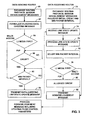
- FIG. 3 is a flowchart illustrating example operation of a receiving router specifying a current transmission credit and a current policer value in accordance with an enhanced routing protocol.
- FIG. 4 is a flowchart illustrating example operation of a sending router transmitting packets in accordance with an enhanced routing protocol.
- FIG. 5 is an example of a multiple broadcast link state message header that has been extended to allow a router to specify a current transmission credit and a current policer value.
- FIG. 1 is a block diagram illustrating an example network system 10 that supports an enhanced link state protocol consistent with the principles of the invention.
- the example network system 10 is shown to include two networks 12A, 12B that use different forms of underlying layer two (L2) communications media.
- network 12A uses "multi-access media" 15 in which all L2 communications for the network are sent to (i.e., broadcasted to) all routers 14A-14F coupled to the network.
- L2 communications media i.e., broadcasted to
- One example of a broadcast network is an Ethernet network, for example, in which an Ethernet frame is communicated to all nodes of the network.
- network 12B uses point-to-point L2 communication media, such as optical links 16A-16D.
- routing protocol update messages are sent between adjacent routers and are processed and terminated by those routers.
- routers 14E, 14F are physically present in both networks 12A and 12B utilizing different physical interfaces provided by the routers.
- network system 10 may include other network devices, such as switches and hubs.
- each of routers 14 typically services a variety of end-user computing devices, such as laptop computers, desktop computers, workstations, personal digital assistants (PDAs), and cellular phones.
- PDAs personal digital assistants
- Network system 10 is shown with respect to networks 12A, 12B that utilize L2 multi-access media 15 and L2 point-to-point media 16 for ease of illustrating the techniques described herein.
- Reference to layers herein, such as L2 and L3, refer to the appropriate layer in the Open Systems Interconnection (OSI) model.
- L2 refers to the data link layer within the OSI model.
- the data link layer may provide the functional and procedural methods to transfer data between the network devices and to detect and possibly correct errors that may occur in the physical layer.
- An example of a L2 communication medium is an Ethernet network.
- L3 refers to the network layer within the OSI model.
- the network layer may provide the functional and procedural methods for transferring variable length data sequences from a source to a destination via one or more networks while maintaining the quality of service requested by higher layers.
- An example of a layer 3 protocol is the Internet Protocol (IP). More information concerning the OSI model can be found in a IEEE publication entitled " OSI Reference Model - the ISO Model of Architecture for Open Systems Interconnection," by Hubret Zimmermann, published in IEEE Transactions on Communications, vol. 28, no. 4, dated April 1980 , which is hereby incorporated by reference as if fully set forth herein.
- routers 14 use flooding-based routing protocols to announce topology information to each other and synchronize link-state databases maintained by each of the routers.
- routers 14 support an enhanced link state protocol (LSP) that has been extended in the manner described herein by which receiving routers that consume topology information are able to control both the average and the burst rate of flood-based transmissions by the sending routers.
- LSP enhanced link state protocol
- a new, opaque Type, Length, Value (TLV) is defined that can be carried by various types of link state messages that are already used within network system 10.
- the TLV may include a first field for carrying a transmission credit that allows a router to control the average rate at which another router floods information to an adjacency.
- the TLV may include a second field for carrying a minimum time interval, e.g., in microseconds, which the sending router must delay between each successive packet transmission. This allows the receiving router to control a policer within the sending router, and thus the packet burst rate, with very low reverse bandwidth consumption.
- the link state messages for the flooding-based routing protocol within network system 10 can be implemented as a "pull" model in which the rate at which topology information is consumed by individual receiving routers 14 ultimately controls the flow of data through the network system.
- the TLV may be carried by a variety of different types of link state messages used within network system 10.
- routers 14 typically exchange initial link state messages to establish the adjacency relationship.
- routers 14 may exchange IS-IS HELLO protocol data units (PDUs) to establish adjacencies with other routers.
- Routers 14 may include the TLV described herein within these initial PDUs so as to inform the other routers as to their data consumption rate requirements.
- routers 14 opaquely include the TLV within the flooding-based link state messages to synchronize link-state databases maintained by each of the routers. Each link state message is typically refreshed periodically on the network and is acknowledged by the receiving routers.
- routers 14 may utilize periodic IS-IS link state PDUs for synchronizing their link-state databases and utilize partial sequence number PDUs (PSNPs) and complete sequence number PDUs (CSNPs) to acknowledge receipt of the information. Routers 14 may embed the TLV within the link state PDUs, or, more likely, within the acknowledgement PDUs.
- PSNPs partial sequence number PDUs
- CSNPs complete sequence number PDUs
- sending routers apply the average- and burst-rate control mechanisms only to "data-carrying" L3 signaling communications that carrying routing topology information of other information for which the routing protocol has been extended to convey. That is, in this embodiment, the sending routers do not apply the control mechanisms to other control messages of the routing protocol that are used to establish and maintain neighbor relationships or to acknowledge the receipt of data and verify database synchronization.
- router 14I within network 12B typically establishes separate adjacencies with routers 14G and 14H as peer routers.
- Router 14I periodically floods link state messages 18A, 18B on links 16A, 16B to ensure that routers 14G-14I maintain synchronized link-state databases.
- routers 14G, 14H Upon receiving the link state messages from router 14I, routers 14G, 14H respond with acknowledgement link state messages 20A, 20B, such as IS-IS PSNPs. This interaction continues so that routers 14I-14H maintain synchronized link-state databases.
- router 141 operates in a first mode in which the router controls the transmission of link state messages 18A on link 15A in accordance with the current transmission credit and minimum time interval most recently specified by router 14G Similarly, router 141 controls the transmission of link state messages 18B on link 16B in accordance with the current transmission credit and minimum time interval most recently specified by router 14H.
- Router 14I may have received the adjacently-specific flow-control mechanisms within opaque TLVs carried by adjacency establishment messages (e.g., IS-IS HELLO messages) or subsequently acknowledgement link state messages 20 (e.g., IS-IS PSNPs) associated with the point-to-point adjacencies between the routers.
- adjacency establishment messages e.g., IS-IS HELLO messages
- acknowledgement link state messages 20 e.g., IS-IS PSNPs
- routers 14A-14F floods multicast link state messages through multi-access media 15, e.g., switched Ethernet media.
- router 14E may output one or more multicast link state messages 22 on multi-access media 15 to flood routing topology information to the multi-access media and receive acknowledgements 24 from each of routers 14A-14D.
- router 14I periodically outputs link state messages 22 to multi-access media 15 as IS-IS link state PDUs and receives acknowledgements 24 in the form of IS-IS CSNPs from each of routers 14A-14D acknowledging receipt of the information.
- router 14E operates in a second mode in which the router controls the transmission of multicast link state messages 22 on multi-access media 15 in accordance with the longest minimum time interval within TLVs carried by acknowledgements 24 without regard to any current transmission credit specified within the TLVs. That is, any packet credit that may have been specified within a TLV of an acknowledgement link state messages 20 (e.g., IS-IS PSNPs) received from broadcast network 12A is ignored by router 12E when transmitting link state messages onto multi-access media 15 of the network.
- each of routers 14A-14F participating in broadcast network 12A transmits data-carrying link state messages in accordance with the current longest minimum packet interval specified by any of the routers. This naturally throttles the packet rate between all neighbors of network 12A to the slowest rate currently required by any of the routers.
- the syntax for multicast mode is that same as point-to-point mode described above with respect to network 12B.
- router 12E may be configured to establish point-to-point routing protocol adjacencies with one or more routers 14A-14D, 14F of broadcast network 12 even though communicating over multi-access media 15.
- router 12E operates in point-to-point mode as described above for each of the adjacencies and, therefore, controls the packet rate based on both the minimum packet interval for the adjacency and the current allocated credit.
- Use of the policer and credit allocation with a mesh of point-to-point adjacencies allows for tight flow control even over multi-access media 15.
- some flooding-based protocols such as IS-IS, utilize multicasting features over multi-access media without relying on periodic retransmission by all of the routers.
- a designated router periodically transmits a digest of the state (in the form of a CSNP) onto multi-access medium (e.g., LAN).
- multi-access medium e.g., LAN
- the router will typically either request missing packets (by sending a PSNP) or multicast the missing packets if the designated router is missing them.
- an administrator may avoid a full mesh of point-to-point adjacencies over the multi-access medium and utilization of multicast mode may provide a sufficient level of flow control and high data transfer rate.
- FIG. 2 is a block diagram illustrating an example encoding of the average and burst rate control information described herein for the IS-IS routing protocol.
- an IS-IS link state PDU is composed of a fixed header and a number of tuples, each consisting of a Type, a Length, and a Value (TLV).
- TLV 40 includes a TYPE field 42, a LENGTH field 44, a VALUE FIELD 45 that is partitioned into a CREDIT sub-field 46 and a MINPACKETINTERVAL sub-field 48.
- TYPE field 42 has a length of one octet that specifies a unique identifier for the new TLV defined herein for carrying the burst rate and average rate control information for the flooding-based routing protocol.
- LENGTH field 44 is one octet in length and indicates the length of the Value field 45 in octets, i.e., six in this example TLV.
- CREDIT sub-field 46 specifies the number of data-carrying link state messages (e.g., IS-IS link state PDUs) that a data-sending router is permitted to transmit. In one embodiment, a value of zero indicates that the data-sending router must stop sending data-carrying link-state messages.
- a data-receiving router can change the credit at any time by including a new TLV 40 within a PSNP or CNSP, with the understanding that lowering the credit for a particular adjacency will not stop the arrival of link state messages already in flight from that sending-router. This sub-field may be ignored by the data-sending router when transmitting link state messages to multi-access media, such as Ethernet.
- MINPACKETINTERVAL sub-field 48 specifies the minimum interval, in microseconds, that the data-sending router of the adjacency must maintain between successive data-carrying packets. As described above, for point-to-point adjacencies, the data-sending router that receives TLV 40 must space data-carrying link state message by at least this interval when transmitting the messages the data-receiving router that originated the TLV. For multi-access media, the data-sending router maintains the longest interval specified by any of the routers participating in the multi-access L2 network.
- TLV 40 is referred to herein as an opaque TLV and the techniques described herein allow for the gradual introduction of this pull model, including burst rate control and average rate control, into existing IS-IS networks.
- FIG. 3 is a flowchart illustrating example operation of a data-sending router and a data-receiving router that utilize and enhanced flooding-based routing protocol in accordance with the principles described herein.
- a pair of routers exchanges session establishment messages to establish an adjacency for the flooding-based routing protocol (60, 72).
- the routers may exchange IS-IS HELLO PDUs to create the adjacency.
- Both the routers may include TLV 40 within it's transmitted IS-IS HELLO PDUs so as to specify initial the burst-rate and average-rate flow control parameters for use by the other routers when sending it data-carrying routing protocol packets.
- Each router may update an internal database, session table or other data structure to store the burst-rate and average-rate flow control parameters specified by the other router for the particular routing protocol adjacency.
- the syntax can be the same for both multicast mode and point-to-point mode.
- TLV 40 may be carried in IS-IS HELLO PDUs for adjacency establishment, or an equivalent construct may be carried by an OSPF HELLO message to negotiate and establish initial credit and burst rate.
- the router If the average-rate and burst-rate control information is not included in session establishment messages by at least one of the routers of the adjacency, it means that the router either has not implemented the flow control scheme or has been configured not to participate in the scheme. In this case, both routers fall back to the existing transmission methods of the flooding-based routing protocol.
- the average-rate and burst-rate control information in session establishment messages serves to establish the initial credit and packet interval, which means that, for example by sending a credit of zero and/or a large inter-packet interval, a router could request a soft startup from its neighbors.
- the TLV within the HELLO messages is interpreted only at initial establishment of the adjacency and may be ignored by the receiving router once the adjacency is established without changing any current settings for the adjacency as specified within acknowledgement messages from the routers. This allows the same Hello packet to be sent indefinitely, which may be useful for distributed packet transmission/absorption mechanisms.
- the routers After establishing a flooding-based routing protocol adjacency, the routers periodically synchronize their link-state databases using flooded link state messages. That is, a data-sending router periodically formulates, and enqueues for transmission, one or more link state messages, such as IS-IS link state PDUs, for refreshing link state information to the other router (62).
- link state messages such as IS-IS link state PDUs
- the router preparing to transmit link state message(s) is referred to as the data-sending router and the other router of the adjacency to which the link state messages will be sent is referred to as the data-receiving router.
- the data-sending router may operate in one of two modes based on whether the routers are coupled by a multi-access L2 communication medium (e.g., Ethernet) or a point-to-point communication medium (e.g., optical links) (64).
- a multi-access L2 communication medium e.g., Ethernet
- a point-to-point communication medium e.g., optical links
- the data-sending router queries the current average-rate flow control to determine whether a current transmission credit has been received for the adjacency to transmit a queued link state message (66). If not, the data-sending router waits for credit to be received (No of 66). If sufficient credit exists for the particular adjacency, the data sending router determines whether the specified minimum packet interval has elapsed since a prior data-carrying link state message has been flooded to the adjacency (68). If not, the data-sending router waits for sufficient time to elapse before proceeding (No of 68). If so, the data-sending router dequeues the link state message, floods the message to the adjacency and resets the packet interval timer (70).
- the data-sending router ignores any average-rate flow control (i.e., credit) specified for the adjacency. Instead, the data sending router only determines whether the specified minimum packet interval has elapsed since a prior data-carrying link state message has been flooded to the adjacency (68). Upon waiting the specified time interval, the data-sending router dequeues the link state message and floods the message to the adjacency (70).
- any average-rate flow control i.e., credit
- the data-receiving router Upon receiving a data-carrying link-state message (74), the data-receiving router processes the message in accordance the link state protocol to update its link-state database (75). In addition, the data-receiving router may adjust its current average-rate control, i.e., minimum packet interval, for the particular adjacency based on its current ability to process incoming packets (76). If the packet was received for an adjacency over point-to-point communication media (78), the data-receiving router also allocates a credit for the adjacency, thereby controlling the burst-rate rate for the maximum number of packets that can be sent before additional credit is required (80).
- the data-receiving router Upon receiving a data-carrying link-state message (74), the data-receiving router processes the message in accordance the link state protocol to update its link-state database (75). In addition, the data-receiving router may adjust its current average-rate control, i
- the data-receiving router may increase or decrease the minimum packet interval and/or allocated credit for the adjacency based on current packet-processing demands placed on the router. These demands may arise from the level of signaling control-plane packets to be processed by the data-receiving router, which may be represented by current queue lengths for inbound signaling packet queues associated with this and other routing-protocol adjacencies.
- the data-receiving router may adjust the minimum packet interval and/or allocate credit for the adjacency based on bandwidth and resources currently being consumed with forwarding transient data-plane traffic. Other criteria that may be considered includes the number of adjacencies currently being maintained by the router for the flooding-based routing protocol.
- the data-receiving router Upon making any adjustments and/or allocating credit for the adjacency, the data-receiving router outputs a link state acknowledgement message that acknowledges receive of the link state update message flooded to the adjacency (82). For example, the data-receiving router may output a partial sequence number PDU or a complete sequence number PDU to acknowledge receipt of the information. At this time, the data-receiving router includes LTV 40 within the link state acknowledgement message to convey to the data-sending router the current minimum packet interval and any credit allocated to the adjacency. In this manner, the techniques allow the flooding-based routing protocol communication mechanism to operate more as a pull-based model in which the data-receiving router has fine-grain control over the rate at which it receives data over the routing adjacency.
- FIG. 4 is a block diagram illustrating an example router 104 configured consistent with the principles of the invention.
- Router 104 may, for example, represent any of routers 14 of FIG. 1 .
- router 104 includes one or more interface cards (IFCs) 106 for sending and receiving packets using network links 112 and 113.
- IFCs 106 are typically coupled to network links 112, 113 via a number of physical interface ports.
- router 104 receives inbound packets from network links 112, determines destinations for the received packets, and outputs the packets on network links 113 based on the destinations.
- network links 112,113 provide L2 communications media for transmitting packets.
- Any of network links 112, 113 may be multi-access media, such as an Ethernet network, or point-to-point media such as optical connections.
- router 104 may be thought of as having a control unit 108 that provides a control plane 103 and a data plane 105.
- Control plane 103 is primarily responsible for maintaining a link-state database (DB) 110 to reflect the current link state data of flooding domain.
- routing engine 68 provides an operating environment for execution of link-state routing protocol 112 that communicate with peer routers and periodically update link state DB 110 to accurately reflect the link state of the flooding domain (e.g., flooding domain 10 of FIG. 1 ) within which router 104 operates.
- Example protocols include routing and label switching protocols, such as IS-IS and OSPF.
- forwarding element 114 maintains forwarding information 116 that associates network destinations or other keying information with specific next hops and corresponding interface ports of output interface cards 106 of router 108.
- Control plane 103 typically processes link state DB 110 to perform route selection and generate forwarding information 116 based on selected routes. In this way, forwarding information may be programmed into data plane 105. Control plane 103 may generate forwarding information 116 in the form of a table, list, radix tree or other data structure.
- U.S. Patent 7,184,437 provides details on an example embodiment of a router that utilizes a radix tree for route resolution, the contents of which is incorporated herein by reference in its entirety.
- forwarding element 114 When forwarding a transient packet, forwarding element 114 traverses forwarding information 116 based on keying information within a header of the packet to ultimately select a next hop and output interface to which to forward the packet. Based on the selection, forwarding element 114 may output the packet directly to the output interface or, in the case of a multi-stage switch fabric of a high-end router, may forward the packet to subsequent stages for switching to the proper output interface.
- Patent Application 2008/0044181 entitled MULTI-CHASSIS ROUTER WITH MULTIPLEXED OPTICAL INTERCONNECTS, describes a multi-chassis router in which a multi-stage switch fabric, such as a 3-stage Clos switch fabric, is used as a high-end forwarding plane to relay packets between multiple routing nodes of the multi-chassis router.
- a multi-stage switch fabric such as a 3-stage Clos switch fabric
- the entire contents of U.S. Patent Application 2008/0044181 are incorporated herein by reference.
- the invention is not limited to this architecture.
- router 104 may be configured in a variety of ways. In one embodiment, for example, all or portions of control plane 103 and data plane 105 may be replicated and incorporated directly within IFCs 106.
- link state routing protocol 112 is a flooding-based communications protocol that has been extended in the manner described herein.
- Control plane 103 includes output queues 120 for storing link state messages for respective routing adjacencies maintained by link state routing protocol 112.
- output queue 120A may store outbound link state messages for a first adjacency while output queue 120B may store outbound link state messages for a first adjacency.
- scheduler 122 operates in accordance with the techniques described herein and set forth above with respect to the flowchart of FIG. 3 .
- schedule 122 controls transmission of the link state messages in accordance with the based on the burst-rate flow control (i.e., minimum, packet interval) and, in the event the adjacency is reachable via a point-to-point communications medium, the average-rate flow control (i.e., credit) specified for the adjacency.
- burst-rate flow control i.e., minimum, packet interval
- the average-rate flow control i.e., credit
- Forwarding element 114 of data plane 105 communicates inbound link state messages 117 to inbound queue 119 for delivery to link state routing protocol 112.
- Link state routing protocol 112 processes the inbound link state messages and updates adjacency data 111 to maintain an entry for each adjacency established with another router.
- each entry within adjacency data 111 specifies an identifier for the adjacency (e.g., IP address), the current credit allocated for the adjacency by the other router, the minimum packet interval for the adjacency as set by the other router, and the type of L2 communication medium by which the adjacency is reachable, i.e., point-to-point or multi-access.
- Link state routing protocol 112 updates the burst-rate and average-rate flow control data for a given adjacency upon receiving an inbound links state message (e.g., an IS-IS HELLO, PSNP or CSNP) for that adjacency that carries TLV 40 described above.
- link state routing protocol 112 parses the credit allocation and the current minimum packet interval set by the TLV and updates adjacency data 111, thereby adjusting the rate at which scheduler 112 transmits output link state messages for that adjacency.
- Adjacencies reachable by the same L2 communications medium i.e., a multi-access medium
- schedule 122 controls the transmission based the longest minimum time interval specified by any of the adjacencies without regard to any current transmission credit for the adjacencies.
- Scheduler 122 maintains a timer 124 for each adjacency, or group of adjacencies in the case of multi-access media, and only outputs a link state message for a given adjacency when the minimum packet interval for that adjacency has been satisfied.
- the techniques may provide an enhanced link state protocol for implemented within the framework of the Open Shortest Path First (OSPF) link state protocol to create a new type of network link state message that allows a router to specify a current transmission credit and a current policer value.
- OSPF Open Shortest Path First
- the equivalent of TLV 40 may be included within OSFP HELLO messages or LSA acknowledgement packets.
- a new type of OSPF LSA may be defined to carry the burst-rate and average-rate flow control information described herein.
- FIG. 5 is an example of a link state message header 158 for carrying the burst-rate and average-rate flow control information described herein.
- Link state message header 200 as shown in the example embodiment of FIG. 5 , complies with the OSPF protocol in that it adheres to the four byte width limitation specified by the OSPF protocol. That is, link state message header 58 comprises a set of four-byte rows, as reflected in FIG. 5 by the 0-31 bit range for each row shown at the top of header 58. Further details of the format of OSPF link state messages can be found in RFC 2328, Internet Engineering Task Force (IETF), April, 1998 herein incorporated by reference.
- IETF Internet Engineering Task Force
- link state message header 158 comprises an link state message age field 60A, options field 60B, LS type field 60C, link state identifier field 60D ("link state ID 60D"), advertising router field 60E, link state sequence number field 60F, link state checksum field 60G, length field 60H, an allocated credit field 60I and a minimum packet interval field 160I.
- link state message header 58 may contain more or less fields 60 shown in FIG. 5 so long as link state message header 58 comprises minimum packet interval field 160I and, optionally, credit field 60I.
- LS age field 60A typically specifies the age of the link state message bearing link state message header 158 in seconds and is used to distinguish between two link state messages specifying the same link state message sequence number in their respective LS sequence number field 60F.
- Options field 60B may specify which optional capabilities are associated with the link state message bearing link state message header 58.
- LS type field 60C indicates the format and function of the link state message bearing link state message header 58, i.e., the type of link state message. If LS type field 60C stores a "1,"for example, the link state message associated with link state message header 58 is designated as a router link state message. Alternatively, if LS type field 60C stores a "2," the link state message defined by link state message header 58 is determined to be a network link state message. LS type field 60C is used herein to indicate that the link state message is a flow-control type used to convey burst-rate and average-rate control information by specifying a different identifier not currently used to define an existing link state message type.
- Link state ID field 60D typically identifies a portion of the routing domain that is being described by the link state message bearing link state message header 58.
- Advertising router field 60E may specify the OSPF router identifiers of the link state message's originator.
- LS sequence number field 60F may-comprise a signed 32-bit integer used to detect old and duplicate link state messages.
- LS checksum field 60G may indicate whether the link state message accompanying link state message header 58 contains errors, and OSPF modules 44 may employ LS checksum field 60G to discard possibly faulty link state messages.
- Length field 60H indicates the length of link state message 158.
- Credit field 60I is a newly defined field that may only appear in a link state message bearing the flow control type in LS type field 60C.
- an OSFP routing protocol supporting the techniques described herein may receive and process the link state message to extract and record the current credit allocation and the minimum packet interval specified by the router that originated the link state message. The receiving router may subsequently use these values to control the rate at which link state messages are flooded to the router.
- link state message header 158 defines a new type of OSPF message
- routers within an OSPF network may select a period for outputting the OSPF messages carrying the information so as to control flooding of data-carrying OSPF LSAs without consuming significant network bandwidth.
- the newly defined type of OSPF message may include topology update information so as to supplant or replace conventional data-carrying LSAs and also convey the rate control information for transmissions in the reverse direction.
- the techniques may be applied to control information flow between distributed components of a single device or system.
- a router e.g., a multi-chassis router
- a flooding-based routing protocol to disseminate link state and other state information between distributed components.
- the techniques described herein allow distributed components (e.g., multiple routing and forwarding components) to implement flooding-based protocols to flood and synchronize state information within the device, yet allow the data-receiving components of the device to individually provide flow control over the flooding of the state information to the respective component.
- the devices may be separate physical components such that the flooding-based protocols sent communications over an internal switch fabric, bus or link.
- the different components may be different virtual machines (e.g., separate virtual routers) operating in a virtual environment provided by a common physical computing environment.
- the components may implement the flooding-based scheme by way of inter-process signaling mechanisms. Examples of network devices that internally communicate state information between distributed components are found in U.S. Patent 7,739,403 , entitled “SYNCHRONIZING STATE INFORMATION BETWEEN CONTROL UNITS," and U.S. Patent Application 11/292,204 , entitled “NON-STOP FORWARDING IN A MULTI-CHASSIS ROUTER.” each of which is hereby incorporated by reference.
Abstract
Description
- This application claims the benefit of
U.S. Provisional Application No. 61/375,166, filed August 19,2010 U.S. Application No. 12/954,099, filed November 24, 2010 - The invention relates to computer networks and, more particularly, to routing protocols used within computer networks.
- A computer network is a collection of interconnected computing devices that exchange data and share resources. In a packet-based network, such as the Internet, the computing devices communicate data by dividing the data into small blocks called packets, which are individually routed across the network from a source device to a destination device. The destination device extracts the data from the packets and assembles the data into its original form.
- Certain devices within the network referred to as routers use routing protocols to exchange and accumulate topology information that describes the network. This allows a router to construct its own routing topology map of the network. Upon receiving an incoming data packet, the router examines keying information within the packet and forwards the packet in accordance with the accumulated topology information.
- Many routing protocols use flooding-based distribution mechanisms to announce topology information to routers within the network. These routing protocols typically rely on routing algorithms that require each of the routers to have synchronized routing topology information. For example, Open Shortest Path First (OSPF) and Intermediate system to intermediate system (IS-IS) routing protocols are link state protocols that use link state messages to ensure their routing topology is synchronized with respect to available interfaces, metrics and other variables associated with network links. For example, OSPF utilizes Link State Advertisements (LSAs) while IS-IS uses Link State protocol data units (LSPs) to exchange information. A router generating a link state message typically floods the link state message throughout the network such that every other router receives the link state message. In network topologies where routers are connected by point-to-point connections, each router floods link state messages to adjacent routers reachable on each interface to ensure synchronization. In networks using multi-access media, such as an Ethernet network, the routers within the network flood the link state messages to all other routers. In either case, the receiving routers construct and maintain their own network topologies using the link information received via the link state messages. IS-IS is specified in "Intermediate system to Intermediate system routing information exchange protocol for use in conjunction with the Protocol for providing the Connectionless-mode Network Service (ISO 8473)", ISO, ISO/IEC 10589:2002, the entire contents of which is incorporated herein by reference.
- Recently, flooding-based routing protocols have been extended to carry significant information between routers that is ancillary to routing control. For example, in addition to carrying topology information, routing protocols have been extended to carry implementation-specific information, such as configuration data, hardware inventory, additional capability information and other information.
- In general, an enhanced, flooding-based routing protocol is described that provides burst-rate and average-rate flow control. The techniques may allow conventional flooding-based routing protocols to be used to synchronize vast amounts of data between routers, yet provide mechanisms by which allow individual receiving routers can control the rate at which each sender floods the information.
- In particular, techniques are described by which receiving routers control both the average rate and the burst rate of flood-based transmission by sending routers. Moreover, control may be achieved in a fail-safe manner that does not overrun receivers. That is, in some circumstances, sending routers may reduce or even halt flooding-based transmissions in the event no affirmative permission is received by a receiving router. By implementing such a mechanism, the distribution mechanism for the flooding-based routing protocol within a network can be implemented as a "pull" model in which the rate at which state information is consumed by individual receiving routers ultimately controls the flow of the state information through the network.
- In one example, the flooding-based routing protocols described herein are extended to incorporate an average rate control that allows a receiving router to continuously control the average rate at which a sending router floods information to an adjacency. In particular, the routing protocol used for communication between the routers carries extended parameters by which the receiving router specifies a transmission credit. In one embodiment, the credit specifies a number of additional packets the sender is permitted to send to the receiver. Alternatively, the credit specifies a number of bytes the sender is permitted to send. Upon sending the specified number of packets or bytes, the sender pauses transmission until additional credit is received. The rate at which credits are advanced by the receiving router determines the average rate at which the sending router transmits the data and allows the receiving router to control the average rate at which the receiving router is required to handle incoming data. The amount of credit advanced at a time and the algorithm by which the receiving routers advance the credits determine the dynamics of the data flow within the network, including the maximum burst size and the average packet throughput, which in turn determines the amount of buffering required at the receiving routers. The receiving routers periodically transmit their credits as reliability mechanisms to avoid deadlock situations where communication failure prevents the sending router from receiving the credit.
- In a second example, the flooding-based routing protocols described herein are extended to allow receiving routers to specify a policier in the form of a minimum inter-packet transmission interval to be applied by the sending router. That is, the receiving router determines and specifies a minimum transmission interval which the sending router must delay between each packet transmission. This provides burst rate control in addition to the average rate control provided by the credit-based scheme, and is applicable to multi-access media such as Ethernet as well as point-to-point links topologies. By implementing such a mechanism, the link state messages for the flooding-based routing protocol within the network system can be implemented as a "pull" model in which the rate at which topology information is consumed by individual receiving routers ultimately controls the flow of data through the network system.
- The mechanism described here can be deployed in a backward-compatible fashion with extensible flooding-based routing protocols, such as IS-IS.
- In one embodiment, a method of controlling transmission of link state messages of a flooding-based link-state routing protocol comprising establishing a link-state routing adjacency between a first router and a second router over a layer-two (L2) communication medium. The method further comprises receiving, with the first routing device, an inbound message in accordance with the flooding-based link state routing protocol. The inbound message specifies a minimum packet interval for the routing adjacency between the first router and the second router. The method further comprises flooding a plurality of link state messages from the first router to the second router over the L2 communication medium to communicate the link state messages. The first router maintains at least the specified minimum packet interval between each of the plurality of link state messages when flooding the messages to the second router.
- In another embodiment, a routing device comprises a network interfaces configured to send and receive packets over a layer-two (L2) communication medium. The routing device further comprises a control unit coupled to the network interface. A flooding-based link state routing protocol executes on a processor of the control unit to maintain network topology information for a network and establish an adjacency with a peer router over the layer-two (L2) communication medium. A database of the routing device stores a minimum packet interval specified by the peer router for the adjacency, and an outbound packet queue stores a plurality of link state messages generated by the link state routing protocol to be flooded to the peer router over the L2 communication medium. The routing device further comprises a scheduler that dequeues the link state messages from the outbound packet queue and floods each of the link state messages to the L2 communication medium, wherein the scheduler maintains at least the specified minimum packet interval between each of the plurality of link state messages when flooding the plurality of link state messages to the L2 communication medium.
- The details of one or more embodiments of the invention are set forth in the accompanying drawings and the description below. Other features, objects, and advantages of the invention will be apparent from the description and drawings, and from the claims.
-
FIG. 1 is a block diagram illustrating an example network system that supports an enhanced link state protocol consistent with the principles of the invention. -
FIG. 2 is a block diagram illustrating a router that supports the enhanced LSP consistent with the principles of the invention. -
FIG. 3 is a flowchart illustrating example operation of a receiving router specifying a current transmission credit and a current policer value in accordance with an enhanced routing protocol. -
FIG. 4 is a flowchart illustrating example operation of a sending router transmitting packets in accordance with an enhanced routing protocol. -
FIG. 5 is an example of a multiple broadcast link state message header that has been extended to allow a router to specify a current transmission credit and a current policer value. -
FIG. 1 is a block diagram illustrating anexample network system 10 that supports an enhanced link state protocol consistent with the principles of the invention. For ease of illustration, theexample network system 10 is shown to include twonetworks network 12A uses "multi-access media" 15 in which all L2 communications for the network are sent to (i.e., broadcasted to) allrouters 14A-14F coupled to the network. One example of a broadcast network is an Ethernet network, for example, in which an Ethernet frame is communicated to all nodes of the network. In contrast,network 12B uses point-to-point L2 communication media, such asoptical links 16A-16D. In this case, routing protocol update messages are sent between adjacent routers and are processed and terminated by those routers. In this example,routers networks FIG. 1 ,network system 10 may include other network devices, such as switches and hubs. Further, although not shown inFIG. 1 , each of routers 14 typically services a variety of end-user computing devices, such as laptop computers, desktop computers, workstations, personal digital assistants (PDAs), and cellular phones. -
Network system 10 is shown with respect tonetworks multi-access media 15 and L2 point-to-point media 16 for ease of illustrating the techniques described herein. Reference to layers herein, such as L2 and L3, refer to the appropriate layer in the Open Systems Interconnection (OSI) model. In particular, L2 refers to the data link layer within the OSI model. The data link layer may provide the functional and procedural methods to transfer data between the network devices and to detect and possibly correct errors that may occur in the physical layer. An example of a L2 communication medium is an Ethernet network. L3 refers to the network layer within the OSI model. The network layer may provide the functional and procedural methods for transferring variable length data sequences from a source to a destination via one or more networks while maintaining the quality of service requested by higher layers. An example of a layer 3 protocol is the Internet Protocol (IP). More information concerning the OSI model can be found in a IEEE publication entitled "OSI Reference Model - the ISO Model of Architecture for Open Systems Interconnection," by Hubret Zimmermann, published in IEEE Transactions on Communications, vol. 28, no. 4, dated April 1980, which is hereby incorporated by reference as if fully set forth herein. - Generally, routers 14 use flooding-based routing protocols to announce topology information to each other and synchronize link-state databases maintained by each of the routers. As described herein, routers 14 support an enhanced link state protocol (LSP) that has been extended in the manner described herein by which receiving routers that consume topology information are able to control both the average and the burst rate of flood-based transmissions by the sending routers. In one example, a new, opaque Type, Length, Value (TLV) is defined that can be carried by various types of link state messages that are already used within
network system 10. The TLV may include a first field for carrying a transmission credit that allows a router to control the average rate at which another router floods information to an adjacency. In addition, the TLV may include a second field for carrying a minimum time interval, e.g., in microseconds, which the sending router must delay between each successive packet transmission. This allows the receiving router to control a policer within the sending router, and thus the packet burst rate, with very low reverse bandwidth consumption. By implementing such a mechanism, the link state messages for the flooding-based routing protocol withinnetwork system 10 can be implemented as a "pull" model in which the rate at which topology information is consumed by individual receiving routers 14 ultimately controls the flow of data through the network system. - The TLV may be carried by a variety of different types of link state messages used within
network system 10. For example, routers 14 typically exchange initial link state messages to establish the adjacency relationship. For example, routers 14 may exchange IS-IS HELLO protocol data units (PDUs) to establish adjacencies with other routers. Routers 14 may include the TLV described herein within these initial PDUs so as to inform the other routers as to their data consumption rate requirements. In addition, or alternatively, routers 14 opaquely include the TLV within the flooding-based link state messages to synchronize link-state databases maintained by each of the routers. Each link state message is typically refreshed periodically on the network and is acknowledged by the receiving routers. For example, routers 14 may utilize periodic IS-IS link state PDUs for synchronizing their link-state databases and utilize partial sequence number PDUs (PSNPs) and complete sequence number PDUs (CSNPs) to acknowledge receipt of the information. Routers 14 may embed the TLV within the link state PDUs, or, more likely, within the acknowledgement PDUs. - In one embodiment sending routers apply the average- and burst-rate control mechanisms only to "data-carrying" L3 signaling communications that carrying routing topology information of other information for which the routing protocol has been extended to convey. That is, in this embodiment, the sending routers do not apply the control mechanisms to other control messages of the routing protocol that are used to establish and maintain neighbor relationships or to acknowledge the receipt of data and verify database synchronization.
- As one example,
router 14I withinnetwork 12B typically establishes separate adjacencies withrouters Router 14I periodically floodslink state messages links routers 14G-14I maintain synchronized link-state databases. Upon receiving the link state messages fromrouter 14I,routers link state messages routers 14I-14H maintain synchronized link-state databases. Throughout this process, router 141 operates in a first mode in which the router controls the transmission oflink state messages 18A on link 15A in accordance with the current transmission credit and minimum time interval most recently specified byrouter 14G Similarly, router 141 controls the transmission oflink state messages 18B onlink 16B in accordance with the current transmission credit and minimum time interval most recently specified byrouter 14H.Router 14I may have received the adjacently- specific flow-control mechanisms within opaque TLVs carried by adjacency establishment messages (e.g., IS-IS HELLO messages) or subsequently acknowledgement link state messages 20 (e.g., IS-IS PSNPs) associated with the point-to-point adjacencies between the routers. - When distributing routing topology information within
broadcast network 12A,routers 14A-14F floods multicast link state messages throughmulti-access media 15, e.g., switched Ethernet media. Continuing the above example, in response to receiving link state messages fromrouter 14G,router 14E may output one or more multicastlink state messages 22 onmulti-access media 15 to flood routing topology information to the multi-access media and receiveacknowledgements 24 from each ofrouters 14A-14D. In one example,router 14I periodically outputslink state messages 22 tomulti-access media 15 as IS-IS link state PDUs and receivesacknowledgements 24 in the form of IS-IS CSNPs from each ofrouters 14A-14D acknowledging receipt of the information. During this process,router 14E operates in a second mode in which the router controls the transmission of multicastlink state messages 22 onmulti-access media 15 in accordance with the longest minimum time interval within TLVs carried byacknowledgements 24 without regard to any current transmission credit specified within the TLVs. That is, any packet credit that may have been specified within a TLV of an acknowledgement link state messages 20 (e.g., IS-IS PSNPs) received frombroadcast network 12A is ignored by router 12E when transmitting link state messages ontomulti-access media 15 of the network. In similar manner, each ofrouters 14A-14F participating inbroadcast network 12A transmits data-carrying link state messages in accordance with the current longest minimum packet interval specified by any of the routers. This naturally throttles the packet rate between all neighbors ofnetwork 12A to the slowest rate currently required by any of the routers. In this example, the syntax for multicast mode is that same as point-to-point mode described above with respect tonetwork 12B. - In some cases, router 12E may be configured to establish point-to-point routing protocol adjacencies with one or
more routers 14A-14D, 14F of broadcast network 12 even though communicating overmulti-access media 15. In this case, router 12E operates in point-to-point mode as described above for each of the adjacencies and, therefore, controls the packet rate based on both the minimum packet interval for the adjacency and the current allocated credit. Use of the policer and credit allocation with a mesh of point-to-point adjacencies allows for tight flow control even overmulti-access media 15. However, some flooding-based protocols, such as IS-IS, utilize multicasting features over multi-access media without relying on periodic retransmission by all of the routers. In IS-IS, for example, a designated router periodically transmits a digest of the state (in the form of a CSNP) onto multi-access medium (e.g., LAN). When another router receives the digest, the router will typically either request missing packets (by sending a PSNP) or multicast the missing packets if the designated router is missing them. This means that on IS-IS enabled router on a LAN can safely discard incoming IS-IS communications without adding any load to the LAN, i.e., without causing any other system on the LAN trying to retransmit the discarded communications to it. In such systems, an administrator may avoid a full mesh of point-to-point adjacencies over the multi-access medium and utilization of multicast mode may provide a sufficient level of flow control and high data transfer rate. -
FIG. 2 is a block diagram illustrating an example encoding of the average and burst rate control information described herein for the IS-IS routing protocol. In general, an IS-IS link state PDU is composed of a fixed header and a number of tuples, each consisting of a Type, a Length, and a Value (TLV). In the example ofFIG. 2 ,TLV 40 includes aTYPE field 42, aLENGTH field 44, aVALUE FIELD 45 that is partitioned into aCREDIT sub-field 46 and aMINPACKETINTERVAL sub-field 48. -
TYPE field 42 has a length of one octet that specifies a unique identifier for the new TLV defined herein for carrying the burst rate and average rate control information for the flooding-based routing protocol.LENGTH field 44 is one octet in length and indicates the length of theValue field 45 in octets, i.e., six in this example TLV. -
CREDIT sub-field 46 specifies the number of data-carrying link state messages (e.g., IS-IS link state PDUs) that a data-sending router is permitted to transmit. In one embodiment, a value of zero indicates that the data-sending router must stop sending data-carrying link-state messages. A data-receiving router can change the credit at any time by including anew TLV 40 within a PSNP or CNSP, with the understanding that lowering the credit for a particular adjacency will not stop the arrival of link state messages already in flight from that sending-router. This sub-field may be ignored by the data-sending router when transmitting link state messages to multi-access media, such as Ethernet. -
MINPACKETINTERVAL sub-field 48 specifies the minimum interval, in microseconds, that the data-sending router of the adjacency must maintain between successive data-carrying packets. As described above, for point-to-point adjacencies, the data-sending router that receivesTLV 40 must space data-carrying link state message by at least this interval when transmitting the messages the data-receiving router that originated the TLV. For multi-access media, the data-sending router maintains the longest interval specified by any of the routers participating in the multi-access L2 network. Incorporation of TLV into PSNPs or CSNPs used to acknowledge receipt of data-carrying link state PDUs, allows the data-receiving routers to control the data-sending router's policer, and thus the packet burst rate, with very low reverse bandwidth. This value can be changed at any time, and once again the data-receiving router that sendsTLV 40 should tolerate latency in the data-sending router's response to the updated interval. A value of zero means that the data-receiving router requires no policer by the data-sending router. Certain values, e.g., 0xFFFFFFF0, may be reserved for special meaning. IS-IS allows the inclusion of TLVs in any kind of IS-IS message and the protocol specification requires that unrecognized TLVs are to be ignored by the routers. In this manner,TLV 40 is referred to herein as an opaque TLV and the techniques described herein allow for the gradual introduction of this pull model, including burst rate control and average rate control, into existing IS-IS networks. -
FIG. 3 is a flowchart illustrating example operation of a data-sending router and a data-receiving router that utilize and enhanced flooding-based routing protocol in accordance with the principles described herein. - Initially, a pair of routers exchanges session establishment messages to establish an adjacency for the flooding-based routing protocol (60, 72). For example, the routers may exchange IS-IS HELLO PDUs to create the adjacency. Both the routers may include
TLV 40 within it's transmitted IS-IS HELLO PDUs so as to specify initial the burst-rate and average-rate flow control parameters for use by the other routers when sending it data-carrying routing protocol packets. Each router may update an internal database, session table or other data structure to store the burst-rate and average-rate flow control parameters specified by the other router for the particular routing protocol adjacency. The syntax can be the same for both multicast mode and point-to-point mode. For example,TLV 40 may be carried in IS-IS HELLO PDUs for adjacency establishment, or an equivalent construct may be carried by an OSPF HELLO message to negotiate and establish initial credit and burst rate. - If the average-rate and burst-rate control information is not included in session establishment messages by at least one of the routers of the adjacency, it means that the router either has not implemented the flow control scheme or has been configured not to participate in the scheme. In this case, both routers fall back to the existing transmission methods of the flooding-based routing protocol.
- The average-rate and burst-rate control information in session establishment messages serves to establish the initial credit and packet interval, which means that, for example by sending a credit of zero and/or a large inter-packet interval, a router could request a soft startup from its neighbors. The TLV within the HELLO messages is interpreted only at initial establishment of the adjacency and may be ignored by the receiving router once the adjacency is established without changing any current settings for the adjacency as specified within acknowledgement messages from the routers. This allows the same Hello packet to be sent indefinitely, which may be useful for distributed packet transmission/absorption mechanisms.
- After establishing a flooding-based routing protocol adjacency, the routers periodically synchronize their link-state databases using flooded link state messages. That is, a data-sending router periodically formulates, and enqueues for transmission, one or more link state messages, such as IS-IS link state PDUs, for refreshing link state information to the other router (62). In this context, the router preparing to transmit link state message(s) is referred to as the data-sending router and the other router of the adjacency to which the link state messages will be sent is referred to as the data-receiving router.
- With respect to outbound link state messages queued for transmission, the data-sending router may operate in one of two modes based on whether the routers are coupled by a multi-access L2 communication medium (e.g., Ethernet) or a point-to-point communication medium (e.g., optical links) (64).
- In the event the adjacency is formed over a point-to-point link, the data-sending router queries the current average-rate flow control to determine whether a current transmission credit has been received for the adjacency to transmit a queued link state message (66). If not, the data-sending router waits for credit to be received (No of 66). If sufficient credit exists for the particular adjacency, the data sending router determines whether the specified minimum packet interval has elapsed since a prior data-carrying link state message has been flooded to the adjacency (68). If not, the data-sending router waits for sufficient time to elapse before proceeding (No of 68). If so, the data-sending router dequeues the link state message, floods the message to the adjacency and resets the packet interval timer (70).
- In the event the adjacency is formed over a multi-access communication medium, the data-sending router ignores any average-rate flow control (i.e., credit) specified for the adjacency. Instead, the data sending router only determines whether the specified minimum packet interval has elapsed since a prior data-carrying link state message has been flooded to the adjacency (68). Upon waiting the specified time interval, the data-sending router dequeues the link state message and floods the message to the adjacency (70).
- Upon receiving a data-carrying link-state message (74), the data-receiving router processes the message in accordance the link state protocol to update its link-state database (75). In addition, the data-receiving router may adjust its current average-rate control, i.e., minimum packet interval, for the particular adjacency based on its current ability to process incoming packets (76). If the packet was received for an adjacency over point-to-point communication media (78), the data-receiving router also allocates a credit for the adjacency, thereby controlling the burst-rate rate for the maximum number of packets that can be sent before additional credit is required (80). The data-receiving router may increase or decrease the minimum packet interval and/or allocated credit for the adjacency based on current packet-processing demands placed on the router. These demands may arise from the level of signaling control-plane packets to be processed by the data-receiving router, which may be represented by current queue lengths for inbound signaling packet queues associated with this and other routing-protocol adjacencies. In addition, the data-receiving router may adjust the minimum packet interval and/or allocate credit for the adjacency based on bandwidth and resources currently being consumed with forwarding transient data-plane traffic. Other criteria that may be considered includes the number of adjacencies currently being maintained by the router for the flooding-based routing protocol.
- Upon making any adjustments and/or allocating credit for the adjacency, the data-receiving router outputs a link state acknowledgement message that acknowledges receive of the link state update message flooded to the adjacency (82). For example, the data-receiving router may output a partial sequence number PDU or a complete sequence number PDU to acknowledge receipt of the information. At this time, the data-receiving router includes
LTV 40 within the link state acknowledgement message to convey to the data-sending router the current minimum packet interval and any credit allocated to the adjacency. In this manner, the techniques allow the flooding-based routing protocol communication mechanism to operate more as a pull-based model in which the data-receiving router has fine-grain control over the rate at which it receives data over the routing adjacency. -
FIG. 4 is a block diagram illustrating anexample router 104 configured consistent with the principles of the invention.Router 104 may, for example, represent any of routers 14 ofFIG. 1 . In the example embodiment illustrated inFIG. 4 ,router 104 includes one or more interface cards (IFCs) 106 for sending and receiving packets usingnetwork links IFCs 106 are typically coupled tonetwork links router 104 receives inbound packets fromnetwork links 112, determines destinations for the received packets, and outputs the packets onnetwork links 113 based on the destinations. In this way, network links 112,113 provide L2 communications media for transmitting packets. Any ofnetwork links - In general,
router 104 may be thought of as having acontrol unit 108 that provides acontrol plane 103 and adata plane 105.Control plane 103 is primarily responsible for maintaining a link-state database (DB) 110 to reflect the current link state data of flooding domain. For example, routingengine 68 provides an operating environment for execution of link-state routing protocol 112 that communicate with peer routers and periodically updatelink state DB 110 to accurately reflect the link state of the flooding domain (e.g.,flooding domain 10 ofFIG. 1 ) within whichrouter 104 operates. Example protocols include routing and label switching protocols, such as IS-IS and OSPF. - In accordance with
link state DB 110, forwardingelement 114 maintains forwardinginformation 116 that associates network destinations or other keying information with specific next hops and corresponding interface ports ofoutput interface cards 106 ofrouter 108.Control plane 103 typically processeslink state DB 110 to perform route selection and generate forwardinginformation 116 based on selected routes. In this way, forwarding information may be programmed intodata plane 105.Control plane 103 may generate forwardinginformation 116 in the form of a table, list, radix tree or other data structure.U.S. Patent 7,184,437 provides details on an example embodiment of a router that utilizes a radix tree for route resolution, the contents of which is incorporated herein by reference in its entirety. - When forwarding a transient packet, forwarding
element 114traverses forwarding information 116 based on keying information within a header of the packet to ultimately select a next hop and output interface to which to forward the packet. Based on the selection, forwardingelement 114 may output the packet directly to the output interface or, in the case of a multi-stage switch fabric of a high-end router, may forward the packet to subsequent stages for switching to the proper output interface.U.S. Patent Application 2008/0044181 , entitled MULTI-CHASSIS ROUTER WITH MULTIPLEXED OPTICAL INTERCONNECTS, describes a multi-chassis router in which a multi-stage switch fabric, such as a 3-stage Clos switch fabric, is used as a high-end forwarding plane to relay packets between multiple routing nodes of the multi-chassis router. The entire contents ofU.S. Patent Application 2008/0044181 are incorporated herein by reference. The invention is not limited to this architecture. In other embodiments,router 104 may be configured in a variety of ways. In one embodiment, for example, all or portions ofcontrol plane 103 anddata plane 105 may be replicated and incorporated directly withinIFCs 106. - As described herein, link
state routing protocol 112 is a flooding-based communications protocol that has been extended in the manner described herein.Control plane 103 includesoutput queues 120 for storing link state messages for respective routing adjacencies maintained by linkstate routing protocol 112. For example,output queue 120A may store outbound link state messages for a first adjacency whileoutput queue 120B may store outbound link state messages for a first adjacency. When dequeuing output link state messages for transmission via forwardingelement 114,scheduler 122 operates in accordance with the techniques described herein and set forth above with respect to the flowchart ofFIG. 3 . That is, with respect to data-carrying link state messages,schedule 122 controls transmission of the link state messages in accordance with the based on the burst-rate flow control (i.e., minimum, packet interval) and, in the event the adjacency is reachable via a point-to-point communications medium, the average-rate flow control (i.e., credit) specified for the adjacency. - Forwarding
element 114 ofdata plane 105 communicates inboundlink state messages 117 toinbound queue 119 for delivery to linkstate routing protocol 112. Linkstate routing protocol 112 processes the inbound link state messages and updates adjacencydata 111 to maintain an entry for each adjacency established with another router. For example, each entry withinadjacency data 111 specifies an identifier for the adjacency (e.g., IP address), the current credit allocated for the adjacency by the other router, the minimum packet interval for the adjacency as set by the other router, and the type of L2 communication medium by which the adjacency is reachable, i.e., point-to-point or multi-access. Linkstate routing protocol 112 updates the burst-rate and average-rate flow control data for a given adjacency upon receiving an inbound links state message (e.g., an IS-IS HELLO, PSNP or CSNP) for that adjacency that carriesTLV 40 described above. In this case, linkstate routing protocol 112 parses the credit allocation and the current minimum packet interval set by the TLV and updates adjacencydata 111, thereby adjusting the rate at whichscheduler 112 transmits output link state messages for that adjacency. - Adjacencies reachable by the same L2 communications medium, i.e., a multi-access medium, may be marked within
adjacency data 111 so as to group the adjacencies records. When dequeing any output link state messages for the group,schedule 122 controls the transmission based the longest minimum time interval specified by any of the adjacencies without regard to any current transmission credit for the adjacencies.Scheduler 122 maintains atimer 124 for each adjacency, or group of adjacencies in the case of multi-access media, and only outputs a link state message for a given adjacency when the minimum packet interval for that adjacency has been satisfied. - In another example, the techniques may provide an enhanced link state protocol for implemented within the framework of the Open Shortest Path First (OSPF) link state protocol to create a new type of network link state message that allows a router to specify a current transmission credit and a current policer value. In one example, the equivalent of
TLV 40 may be included within OSFP HELLO messages or LSA acknowledgement packets. In another example, a new type of OSPF LSA may be defined to carry the burst-rate and average-rate flow control information described herein. -
FIG. 5 is an example of a linkstate message header 158 for carrying the burst-rate and average-rate flow control information described herein. Link state message header 200, as shown in the example embodiment ofFIG. 5 , complies with the OSPF protocol in that it adheres to the four byte width limitation specified by the OSPF protocol. That is, link state message header 58 comprises a set of four-byte rows, as reflected inFIG. 5 by the 0-31 bit range for each row shown at the top of header 58. Further details of the format of OSPF link state messages can be found in RFC 2328, Internet Engineering Task Force (IETF), April, 1998 herein incorporated by reference. - As shown in
FIG. 5 , linkstate message header 158 comprises an link state message age field 60A, options field 60B, LS type field 60C, link state identifier field 60D ("link state ID 60D"), advertising router field 60E, link state sequence number field 60F, link state checksum field 60G, length field 60H, an allocated credit field 60I and a minimum packet interval field 160I. Although shown as contain fields 60A-60I ("fields 60"), link state message header 58 may contain more orless fields 60 shown inFIG. 5 so long as link state message header 58 comprises minimum packet interval field 160I and, optionally, credit field 60I. - LS age field 60A typically specifies the age of the link state message bearing link
state message header 158 in seconds and is used to distinguish between two link state messages specifying the same link state message sequence number in their respective LS sequence number field 60F. Options field 60B may specify which optional capabilities are associated with the link state message bearing link state message header 58. - LS type field 60C indicates the format and function of the link state message bearing link state message header 58, i.e., the type of link state message. If LS type field 60C stores a "1,"for example, the link state message associated with link state message header 58 is designated as a router link state message. Alternatively, if LS type field 60C stores a "2," the link state message defined by link state message header 58 is determined to be a network link state message. LS type field 60C is used herein to indicate that the link state message is a flow-control type used to convey burst-rate and average-rate control information by specifying a different identifier not currently used to define an existing link state message type.
- Link state ID field 60D typically identifies a portion of the routing domain that is being described by the link state message bearing link state message header 58. Advertising router field 60E may specify the OSPF router identifiers of the link state message's originator. LS sequence number field 60F may-comprise a signed 32-bit integer used to detect old and duplicate link state messages. LS checksum field 60G may indicate whether the link state message accompanying link state message header 58 contains errors, and
OSPF modules 44 may employ LS checksum field 60G to discard possibly faulty link state messages. Length field 60H indicates the length oflink state message 158. - Credit field 60I is a newly defined field that may only appear in a link state message bearing the flow control type in LS type field 60C. In the event such a value is designated in field 60C, an OSFP routing protocol supporting the techniques described herein may receive and process the link state message to extract and record the current credit allocation and the minimum packet interval specified by the router that originated the link state message. The receiving router may subsequently use these values to control the rate at which link state messages are flooded to the router. As link
state message header 158 defines a new type of OSPF message, routers within an OSPF network may select a period for outputting the OSPF messages carrying the information so as to control flooding of data-carrying OSPF LSAs without consuming significant network bandwidth. In addition, or alternatively, the newly defined type of OSPF message may include topology update information so as to supplant or replace conventional data-carrying LSAs and also convey the rate control information for transmissions in the reverse direction. - Although the techniques have been described with respect to providing burst-rate and average-rate flow control to flooding-based routing protocols to synchronize data between routers, the techniques may be applied to control information flow between distributed components of a single device or system. For example, it is contemplated that a router (e.g., a multi-chassis router) or other complex network device may internally utilize a flooding-based routing protocol to disseminate link state and other state information between distributed components. In this case, the techniques described herein allow distributed components (e.g., multiple routing and forwarding components) to implement flooding-based protocols to flood and synchronize state information within the device, yet allow the data-receiving components of the device to individually provide flow control over the flooding of the state information to the respective component. The devices may be separate physical components such that the flooding-based protocols sent communications over an internal switch fabric, bus or link. Alternatively, the different components may be different virtual machines (e.g., separate virtual routers) operating in a virtual environment provided by a common physical computing environment. In this case, the components may implement the flooding-based scheme by way of inter-process signaling mechanisms. Examples of network devices that internally communicate state information between distributed components are found in
U.S. Patent 7,739,403 , entitled "SYNCHRONIZING STATE INFORMATION BETWEEN CONTROL UNITS," andU.S. Patent Application 11/292,204 , entitled "NON-STOP FORWARDING IN A MULTI-CHASSIS ROUTER." each of which is hereby incorporated by reference. - Various embodiments of the invention have been described. These and other embodiments are within the scope of the following claims.
Claims (17)
- A method of controlling transmission of link state messages of a flooding-based link-state routing protocol, the method comprising:establishing a link-state routing adjacency between a first router and a second router over a layer-two, "L2", communication medium;receiving, with the first routing device, an inbound message in accordance with the flooding-based link state routing protocol, wherein the inbound message specifies a minimum packet interval for the routing adjacency between the first router and the second router; andflooding a plurality of link state messages from the first router to the second router over the L2 communication medium to communicate the link state messages, wherein the first router maintains at least the specified minimum packet interval between each of the plurality of link state messages when flooding the plurality of link state messages to the L2 communication medium.
- The method of claim 1, further comprising:determining, with the first router, whether the L2 communication medium comprises a multi-access communication medium or a point-to-point communication medium,when the L2 communication medium comprises a point-to-point communication medium, operating the first router in a first mode in which the first router outputs the plurality of link state messages with the first router to the L2 communication medium with a time interval between successive packets that exceeds the minimum packet interval for the adjacency; andwhen the L2 communication medium comprises a multi-access communication medium, operating the first router in a second mode in which the first router: (a) identifies a longest minimum packet interval specified by any router within a group of routers having adjacencies with the first router and reachable through the same L2 communication medium, and (b) floods the plurality of link state messages with the first router to the L2 communication medium with a time interval between successive packets that exceeds the identified minimum packet interval for the group of routers.
- The method of claim 1 or claim 2,
wherein the inbound message further specifies a packet credit allocated to the adjacency by the second router, and
wherein flooding a plurality of link state messages from the first router to the second router over the L2 communication medium comprises flooding a subset of the plurality of link state messages with the first router up to the allocated packet credit and waiting until additional credit is received from the second router before flooding a remaining portion of the plurality of link state messages. - The method of claim 3, wherein the packet credit specifies one of a number of packets or a number of bytes allocated for the routing-protocol adjacency.
- The method of claim 3 or claim 4, wherein the inbound message includes a Type, Length, and Value, "TLV", that includes a first sub-field to specify the minimum packet interval for the adjacency and a second sub-field to specify the packet credit allocated to the adjacency by the second router.
- The method of claim 5, wherein the inbound message comprises an IS-IS HELLO protocol data unit that contains the TLV.
- The method of claim 5 or claim 6, further comprising:prior to receiving the inbound link state message, sending one or more link state messages from the first router to the second router to synchronize link-state databases of the first router and the second router; andreceiving the inbound message with the first router in response to the previously sent link state messages, wherein the inbound message comprises an IS-IS partial sequence number PDUs, "PSNPs", that acknowledges receipt of the previously sent link state messages and contains the TLV that specifies the minimum packet interval and the packet credit.
- The method of claim 1,
wherein the inbound message further specifies a packet credit allocated to the adjacency by the second router, the method further comprising:determining, with the first router, whether the L2 communication medium comprises a multi-access communication medium or a point-to-point communication medium;when the L2 communication medium comprises a point-to-point communication medium, controlling the flooding of the plurality of link state messages from the first router to the second router in accordance with the allocated packet credit by outputting a subset of the plurality of link state messages with the first router up to the allocated packet credit and waiting until additional credit is received from the second router before outputting a remaining portion of the plurality of link state messages; andwhen the L2 communication medium comprises a multi-access communication medium, flooding the plurality of link state messages from the first router to the second router over the L2 communication medium without regard to the packet credit specified for the adjacency by the inbound link state message. - A routing device comprising:a network interfaces configured to send and receive packets over a layer-two, "L2", communication medium;a control unit coupled to the network interface;a flooding-based link state routing protocol executing on a processor of the control unit to maintain network topology information for a network, wherein the link-state routing protocol establishes an adjacency with a peer router over the L2 communication medium;a database that stores a minimum packet interval specified by the peer router for the adjacency;an outbound packet queue to store a plurality of link state messages generated by the link state routing protocol to be flooded to the peer router over the L2 communication medium; anda scheduler that dequeues the link state messages from the outbound packet queue and floods each of the link state messages to the L2 communication medium, wherein the scheduler maintains at least the specified minimum packet interval between each of the plurality of link state messages when flooding the plurality of link state messages to the L2 communication medium.
- The routing device of claim 9,
wherein the database includes records for a plurality of routers with which the routing device maintains link-state routing protocol adjacencies over the L2 communication medium, each of the records specifying a minimum packet interval specified by the respective router for flooding link state messages to the router,
wherein, when the L2 communication medium comprises a point-to-point communication medium, the scheduler operates in a first mode in which the scheduler floods the plurality of link state messages to the L2 communication medium with a time interval between successive link state messages that exceeds the minimum packet interval specified by the peer router, and
wherein, when the L2 communication medium comprises a multi-access communication medium, the scheduler operates in a second mode in which the scheduler:(a) accesses the database to identify a longest minimum packet interval specified by any of the plurality of routers having the adjacencies over the L2 communication medium, and(b) floods the plurality of link state messages to the L2 communication medium with a time interval between successive link state messages that exceeds the identified minimum packet interval for the plurality of routers. - The routing device of claim 9, or claim 10
wherein the database stores data specifying a packet credit currently allocated to the adjacency by the peer router, and
wherein the scheduler floods the plurality of link state messages a subset of the plurality of link state messages with the first router up to the allocated packet credit and waits until additional credit is received from the peer router before flooding a remaining portion of the plurality of link state messages. - The routing device of claim 11, wherein the packet credit specifies one of a number of packets or a number of bytes allocated for the routing-protocol adjacency.
- The routing device of claim 11,
wherein the link state routing protocol receives an inbound message from the peer router having a Type, Length, and Value, "TLV", that includes a first sub-field to specify the minimum packet interval for the adjacency and a second sub-field to specify the packet credit allocated to the adjacency by the peer router, and
wherein the link state routing protocol updates the database based on the minimum packet interval and the packet credit specified within the TLV. - The routing device of claim 13, wherein the inbound message comprises an intermediate system to intermediate system, "IS-IS", routing protocol HELLO protocol data unit that contains the TLV.
- The routing device of claim 13, wherein the inbound message comprises an IS-IS partial sequence number PDUs "PSNPs", that acknowledges receipt of previously sent link state messages and contains the TLV that specifies the minimum packet interval and the packet credit.
- The routing device of any one of claims 9 to 15,
wherein the link state routing protocol receives Open Shortest Path First, "OSPF", link state advertisement that includes a header that specifies minimum packet interval and the packet credit allocated to the adjacency by the peer router, and
wherein the link state routing protocol updates the database based on the minimum packet interval and the packet credit specified within the OSPF header. - The routing device of claim 9,
wherein the database includes records for a plurality of routers with which the routing device maintains link-state routing protocol adjacencies over the L2 communication medium, each of the records specifying a minimum packet interval and a packet credit specified by the respective router for flooding link state messages to the router,
when the L2 communication medium comprises a point-to-point communication medium, the scheduler operates in a first mode in which the scheduler floods a subset of the plurality of link state messages to the L2 communication medium up to the allocated packet credit and waiting until additional credit is received from the peer router before flooding a remaining portion of the plurality of link state messages; and
when the L2 communication medium comprises a multi-access communication medium, the scheduler operates in a second mode in which the scheduler floods the plurality of link state messages from the first router to the peer router over the L2 communication medium without regard to the packet credit specified for the adjacency by the inbound link state message.
Applications Claiming Priority (2)
| Application Number | Priority Date | Filing Date | Title |
|---|---|---|---|
| US37516610P | 2010-08-19 | 2010-08-19 | |
| US12/954,099 US8498299B2 (en) | 2010-08-19 | 2010-11-24 | Flooding-based routing protocol having average-rate and burst-rate control |
Publications (2)
| Publication Number | Publication Date |
|---|---|
| EP2421205A1 true EP2421205A1 (en) | 2012-02-22 |
| EP2421205B1 EP2421205B1 (en) | 2018-10-03 |
Family
ID=44532662
Family Applications (1)
| Application Number | Title | Priority Date | Filing Date |
|---|---|---|---|
| EP11177070.7A Active EP2421205B1 (en) | 2010-08-19 | 2011-08-10 | Flooding-based routing protocol having average-rate and burst-rate control |
Country Status (3)
| Country | Link |
|---|---|
| US (1) | US8498299B2 (en) |
| EP (1) | EP2421205B1 (en) |
| CN (1) | CN102377666B (en) |
Families Citing this family (26)
| Publication number | Priority date | Publication date | Assignee | Title |
|---|---|---|---|---|
| US7684786B2 (en) * | 2003-08-26 | 2010-03-23 | Nokia Corporation | Method and system for establishing a connection between network elements |
| US8670450B2 (en) | 2011-05-13 | 2014-03-11 | International Business Machines Corporation | Efficient software-based private VLAN solution for distributed virtual switches |
| US9276953B2 (en) | 2011-05-13 | 2016-03-01 | International Business Machines Corporation | Method and apparatus to detect and block unauthorized MAC address by virtual machine aware network switches |
| US20120291034A1 (en) | 2011-05-14 | 2012-11-15 | International Business Machines Corporation | Techniques for executing threads in a computing environment |
| US8837499B2 (en) | 2011-05-14 | 2014-09-16 | International Business Machines Corporation | Distributed fabric protocol (DFP) switching network architecture |
| US20120287785A1 (en) | 2011-05-14 | 2012-11-15 | International Business Machines Corporation | Data traffic handling in a distributed fabric protocol (dfp) switching network architecture |
| US9497073B2 (en) | 2011-06-17 | 2016-11-15 | International Business Machines Corporation | Distributed link aggregation group (LAG) for a layer 2 fabric |
| US8767529B2 (en) | 2011-09-12 | 2014-07-01 | International Business Machines Corporation | High availability distributed fabric protocol (DFP) switching network architecture |
| US20130064066A1 (en) | 2011-09-12 | 2013-03-14 | International Business Machines Corporation | Updating a switch software image in a distributed fabric protocol (dfp) switching network |
| US9065745B2 (en) | 2011-10-06 | 2015-06-23 | International Business Machines Corporation | Network traffic distribution |
| US8750129B2 (en) * | 2011-10-06 | 2014-06-10 | International Business Machines Corporation | Credit-based network congestion management |
| WO2016175874A1 (en) | 2015-04-30 | 2016-11-03 | Hewlett Packard Enterprise Development Lp | Reducing flooding of route updates of a dynamic routing protocol |
| US10594505B2 (en) * | 2016-01-27 | 2020-03-17 | Quanta Computer Inc. | System and method for avoiding deadlock in transmission of broadcast traffic in a server system |
| US10630590B2 (en) * | 2016-07-14 | 2020-04-21 | Mellanox Technologies Tlv Ltd. | Credit loop deadlock detection and recovery in arbitrary topology networks |
| US10516549B2 (en) * | 2016-08-02 | 2019-12-24 | Cisco Technology, Inc. | Multicast service with is-is spine-leaf extension in a fabric network |
| CN116938726A (en) * | 2018-09-12 | 2023-10-24 | 华为技术有限公司 | System and method for backup flooding topology separation |
| US20200084109A1 (en) * | 2018-09-12 | 2020-03-12 | Nokia Solutions And Networks Oy | Sparse link-state flooding |
| US11477289B2 (en) * | 2018-10-09 | 2022-10-18 | Nokia Solutions And Networks Oy | Supporting a routing protocol with a transport layer protocol |
| US11483087B2 (en) | 2020-08-07 | 2022-10-25 | Hyannis Port Research, Inc. | Systems and methods for clock synchronization using special physical layer clock sync symbols |
| US11683199B2 (en) | 2020-08-07 | 2023-06-20 | Hyannis Port Research, Inc. | Distributed system with fault tolerance and self-maintenance |
| US11088959B1 (en) | 2020-08-07 | 2021-08-10 | Hyannis Port Research, Inc. | Highly deterministic latency in a distributed system |
| US11328357B2 (en) | 2020-08-07 | 2022-05-10 | Hyannis Port Research, Inc. | Sequencer bypass with transactional preprocessing in distributed system |
| US11315183B2 (en) | 2020-08-07 | 2022-04-26 | Hyannis Port Research, Inc. | Electronic trading system and method based on point-to-point mesh architecture |
| US11303389B2 (en) | 2020-08-07 | 2022-04-12 | Hyannis Port Research, Inc. | Systems and methods of low latency data communication for physical link layer reliability |
| US11228529B1 (en) | 2020-08-07 | 2022-01-18 | Hyannis Port Research, Inc. | Local and global quality of service shaper on ingress in a distributed system |
| CN114389759A (en) * | 2021-12-28 | 2022-04-22 | 福建天晴数码有限公司 | Message transmission method and system |
Citations (3)
| Publication number | Priority date | Publication date | Assignee | Title |
|---|---|---|---|---|
| US7184437B1 (en) | 2002-07-17 | 2007-02-27 | Juniper Networks, Inc. | Scalable route resolution |
| US20080044181A1 (en) | 2006-08-21 | 2008-02-21 | Juniper Networks, Inc. | Multi-chassis router with multiplexed optical interconnects |
| US7739403B1 (en) | 2003-10-03 | 2010-06-15 | Juniper Networks, Inc. | Synchronizing state information between control units |
Family Cites Families (3)
| Publication number | Priority date | Publication date | Assignee | Title |
|---|---|---|---|---|
| US7804769B1 (en) | 2005-12-01 | 2010-09-28 | Juniper Networks, Inc. | Non-stop forwarding in a multi-chassis router |
| US8442046B2 (en) * | 2007-03-30 | 2013-05-14 | Cisco Technology, Inc. | Sending routing protocol data on a multi-access network segment |
| US7876710B2 (en) * | 2008-07-30 | 2011-01-25 | Juniper Networks, Inc. | Layer two MAC flushing/re-routing |
-
2010
- 2010-11-24 US US12/954,099 patent/US8498299B2/en active Active
-
2011
- 2011-08-10 EP EP11177070.7A patent/EP2421205B1/en active Active
- 2011-08-19 CN CN201110240610.5A patent/CN102377666B/en active Active
Patent Citations (3)
| Publication number | Priority date | Publication date | Assignee | Title |
|---|---|---|---|---|
| US7184437B1 (en) | 2002-07-17 | 2007-02-27 | Juniper Networks, Inc. | Scalable route resolution |
| US7739403B1 (en) | 2003-10-03 | 2010-06-15 | Juniper Networks, Inc. | Synchronizing state information between control units |
| US20080044181A1 (en) | 2006-08-21 | 2008-02-21 | Juniper Networks, Inc. | Multi-chassis router with multiplexed optical interconnects |
Non-Patent Citations (5)
| Title |
|---|
| ALEX ZININ MIKE SHAND CISCO SYSTEMS: "Flooding optimizations in link-state routing protocols; draft-ietf-ospf-isis-flood-opt-01.txt", IETF STANDARD-WORKING-DRAFT, INTERNET ENGINEERING TASK FORCE, IETF, CH, vol. ospf, no. 1, 1 March 2001 (2001-03-01), XP015024685, ISSN: 0000-0004 * |
| CHOUDHURY G ET AL: "Prioritized Treatment of Specific OSPF Version 2 Packets and Congestion Avoidance; rfc4222.txt", IETF STANDARD, INTERNET ENGINEERING TASK FORCE, IETF, CH, 1 October 2005 (2005-10-01), XP015054900, ISSN: 0000-0003 * |
| HUBRET ZIMMERMANN: "OSI Reference Model - the ISO Model of Architecture for Open Systems Interconnection", IEEE TRANSACTIONS ON COMMUNICATIONS, vol. 28, no. 4, April 1980 (1980-04-01) |
| JERRY ASH GAGAN L CHOUDHURY VERA D SAPOZHNIKOVA MOSTAFA SHERIF AT&T VISHWAS MANRAL NETPLANE SYSTEMS ANURAG MAUNDER SANERA SYSTEMS: "Congestion Avoidance & Control for OSPF Networks <draft-ash-manral-ospf-congestion-control-00.txt>; draft-ash-manral-ospf-congestion-control-00.txt", IETF STANDARD-WORKING-DRAFT, INTERNET ENGINEERING TASK FORCE, IETF, CH, 1 April 2002 (2002-04-01), XP015000139, ISSN: 0000-0004 * |
| SCHOENEN R ET AL: "CLOSED LOOP CREDIT-BASED FLOW CONTROL WITH INTERNAL BACKPRESSURE IN INPUT AND OUTPUT QUEUED SWITCHES", PROCEEDINGS OF THE IEEE CONFERENCE 2000 ON HIGH PERFORMANCE SWITCHING AND ROUTING. HEIDELBERG, GERMANY, JUNE, 26 - 29, 2000; [PROCEEDINGS OF THE IEEE CONFERENCE ON HIGH PERFORMANCE SWITCHING AND ROUTING], NEW YORK, NY : IEEE, US, 26 June 2000 (2000-06-26), pages 195 - 203, XP001075703, ISBN: 978-0-7803-5884-3, DOI: 10.1109/HPSR.2000.856664 * |
Also Published As
| Publication number | Publication date |
|---|---|
| US20120044940A1 (en) | 2012-02-23 |
| CN102377666B (en) | 2014-07-09 |
| US8498299B2 (en) | 2013-07-30 |
| EP2421205B1 (en) | 2018-10-03 |
| CN102377666A (en) | 2012-03-14 |
Similar Documents
| Publication | Publication Date | Title |
|---|---|---|
| EP2421205B1 (en) | Flooding-based routing protocol having average-rate and burst-rate control | |
| CN110139319B (en) | Routing method for minimizing transmission delay of high dynamic delay network | |
| US8243594B1 (en) | Coordinated control of multiple parallel links or link aggregations | |
| EP2421206B1 (en) | Flooding-based routing protocol having database pruning and rate-controlled state refresh | |
| US7065059B1 (en) | Technique for restoring adjacencies in OSPF in a non-stop forwarding intermediate node of a computer network | |
| US9197583B2 (en) | Signaling of attachment circuit status and automatic discovery of inter-chassis communication peers | |
| EP1716500B1 (en) | Apparatus, method,system and computer program product for communicating packets in a network environment | |
| EP2274880B1 (en) | Method and apparatus for link-state handshake for loop prevention | |
| EP1557013B1 (en) | Rpf multi-party reliable transport | |
| US6950427B1 (en) | Technique for resynchronizing LSDB in OSPF after a software reload in a non-stop forwarding intermediate node of a computer network | |
| US20090046719A1 (en) | Method and Apparatus for Implementing Multiple Portals into an RBRIDGE Network | |
| US8913485B2 (en) | Open shortest path first (OSPF) nonstop routing (NSR) with link derivation | |
| US7234000B2 (en) | System and method of downloading configuration data from a central location to components for a communication switch | |
| EP3035592B1 (en) | Enhanced protocol independent multicast source registration over a reliable transport | |
| US20080137669A1 (en) | Network of nodes | |
| US7388862B2 (en) | Technique for notifying EIGRP neighbors when destroying adjacencies in a computer network | |
| KR100450951B1 (en) | Redundancy mechanization protocol for a massively parallel router | |
| US11677586B1 (en) | Fast convergence for MAC mobility | |
| EP2575304B1 (en) | OSPF nonstop routing (NSR) synchronization reduction | |
| US11374856B1 (en) | System and method for performing synchronization of maximum transmission unit with router redundancy | |
| Kodikara et al. | ConEx: Context Exchange in MANETs for real time multimedia | |
| Roshni et al. | BUNDLE PROTOCOL ALONG WITH OLSR IN MANET | |
| EP1333614A2 (en) | System and method of downloading data for a communication switch | |
| Liu et al. | Generic Fault-Avoidance Routing Protocol for Data Center Networks | |
| Loganathan et al. | PERFORMANCE COMPARISON OF AOMDV AND EGMP FOR VIDEO TRANSMISSION IN MOBILE ADHOC NETWORK |
Legal Events
| Date | Code | Title | Description |
|---|---|---|---|
| AK | Designated contracting states |
Kind code of ref document: A1 Designated state(s): AL AT BE BG CH CY CZ DE DK EE ES FI FR GB GR HR HU IE IS IT LI LT LU LV MC MK MT NL NO PL PT RO RS SE SI SK SM TR |
|
| AX | Request for extension of the european patent |
Extension state: BA ME |
|
| PUAI | Public reference made under article 153(3) epc to a published international application that has entered the european phase |
Free format text: ORIGINAL CODE: 0009012 |
|
| 17P | Request for examination filed |
Effective date: 20120705 |
|
| 17Q | First examination report despatched |
Effective date: 20121004 |
|
| RAP1 | Party data changed (applicant data changed or rights of an application transferred) |
Owner name: JUNIPER NETWORKS, INC. |
|
| REG | Reference to a national code |
Ref country code: DE Ref legal event code: R079 Ref document number: 602011052498 Country of ref document: DE Free format text: PREVIOUS MAIN CLASS: H04L0012460000 Ipc: H04L0012700000 |
|
| GRAP | Despatch of communication of intention to grant a patent |
Free format text: ORIGINAL CODE: EPIDOSNIGR1 |
|
| STAA | Information on the status of an ep patent application or granted ep patent |
Free format text: STATUS: GRANT OF PATENT IS INTENDED |
|
| RIC1 | Information provided on ipc code assigned before grant |
Ipc: H04L 12/70 20130101AFI20180312BHEP |
|
| INTG | Intention to grant announced |
Effective date: 20180405 |
|
| GRAS | Grant fee paid |
Free format text: ORIGINAL CODE: EPIDOSNIGR3 |
|
| GRAA | (expected) grant |
Free format text: ORIGINAL CODE: 0009210 |
|
| STAA | Information on the status of an ep patent application or granted ep patent |
Free format text: STATUS: THE PATENT HAS BEEN GRANTED |
|
| AK | Designated contracting states |
Kind code of ref document: B1 Designated state(s): AL AT BE BG CH CY CZ DE DK EE ES FI FR GB GR HR HU IE IS IT LI LT LU LV MC MK MT NL NO PL PT RO RS SE SI SK SM TR |
|
| REG | Reference to a national code |
Ref country code: GB Ref legal event code: FG4D |
|
| REG | Reference to a national code |
Ref country code: CH Ref legal event code: EP Ref country code: AT Ref legal event code: REF Ref document number: 1049839 Country of ref document: AT Kind code of ref document: T Effective date: 20181015 |
|
| REG | Reference to a national code |
Ref country code: DE Ref legal event code: R096 Ref document number: 602011052498 Country of ref document: DE Ref country code: IE Ref legal event code: FG4D |
|
| REG | Reference to a national code |
Ref country code: NL Ref legal event code: MP Effective date: 20181003 |
|
| REG | Reference to a national code |
Ref country code: LT Ref legal event code: MG4D |
|
| REG | Reference to a national code |
Ref country code: AT Ref legal event code: MK05 Ref document number: 1049839 Country of ref document: AT Kind code of ref document: T Effective date: 20181003 |
|
| PG25 | Lapsed in a contracting state [announced via postgrant information from national office to epo] |
Ref country code: NL Free format text: LAPSE BECAUSE OF FAILURE TO SUBMIT A TRANSLATION OF THE DESCRIPTION OR TO PAY THE FEE WITHIN THE PRESCRIBED TIME-LIMIT Effective date: 20181003 |
|
| PG25 | Lapsed in a contracting state [announced via postgrant information from national office to epo] |
Ref country code: CZ Free format text: LAPSE BECAUSE OF FAILURE TO SUBMIT A TRANSLATION OF THE DESCRIPTION OR TO PAY THE FEE WITHIN THE PRESCRIBED TIME-LIMIT Effective date: 20181003 Ref country code: FI Free format text: LAPSE BECAUSE OF FAILURE TO SUBMIT A TRANSLATION OF THE DESCRIPTION OR TO PAY THE FEE WITHIN THE PRESCRIBED TIME-LIMIT Effective date: 20181003 Ref country code: AT Free format text: LAPSE BECAUSE OF FAILURE TO SUBMIT A TRANSLATION OF THE DESCRIPTION OR TO PAY THE FEE WITHIN THE PRESCRIBED TIME-LIMIT Effective date: 20181003 Ref country code: PL Free format text: LAPSE BECAUSE OF FAILURE TO SUBMIT A TRANSLATION OF THE DESCRIPTION OR TO PAY THE FEE WITHIN THE PRESCRIBED TIME-LIMIT Effective date: 20181003 Ref country code: HR Free format text: LAPSE BECAUSE OF FAILURE TO SUBMIT A TRANSLATION OF THE DESCRIPTION OR TO PAY THE FEE WITHIN THE PRESCRIBED TIME-LIMIT Effective date: 20181003 Ref country code: LT Free format text: LAPSE BECAUSE OF FAILURE TO SUBMIT A TRANSLATION OF THE DESCRIPTION OR TO PAY THE FEE WITHIN THE PRESCRIBED TIME-LIMIT Effective date: 20181003 Ref country code: LV Free format text: LAPSE BECAUSE OF FAILURE TO SUBMIT A TRANSLATION OF THE DESCRIPTION OR TO PAY THE FEE WITHIN THE PRESCRIBED TIME-LIMIT Effective date: 20181003 Ref country code: NO Free format text: LAPSE BECAUSE OF FAILURE TO SUBMIT A TRANSLATION OF THE DESCRIPTION OR TO PAY THE FEE WITHIN THE PRESCRIBED TIME-LIMIT Effective date: 20190103 Ref country code: IS Free format text: LAPSE BECAUSE OF FAILURE TO SUBMIT A TRANSLATION OF THE DESCRIPTION OR TO PAY THE FEE WITHIN THE PRESCRIBED TIME-LIMIT Effective date: 20190203 Ref country code: ES Free format text: LAPSE BECAUSE OF FAILURE TO SUBMIT A TRANSLATION OF THE DESCRIPTION OR TO PAY THE FEE WITHIN THE PRESCRIBED TIME-LIMIT Effective date: 20181003 Ref country code: BG Free format text: LAPSE BECAUSE OF FAILURE TO SUBMIT A TRANSLATION OF THE DESCRIPTION OR TO PAY THE FEE WITHIN THE PRESCRIBED TIME-LIMIT Effective date: 20190103 |
|
| PG25 | Lapsed in a contracting state [announced via postgrant information from national office to epo] |
Ref country code: AL Free format text: LAPSE BECAUSE OF FAILURE TO SUBMIT A TRANSLATION OF THE DESCRIPTION OR TO PAY THE FEE WITHIN THE PRESCRIBED TIME-LIMIT Effective date: 20181003 Ref country code: PT Free format text: LAPSE BECAUSE OF FAILURE TO SUBMIT A TRANSLATION OF THE DESCRIPTION OR TO PAY THE FEE WITHIN THE PRESCRIBED TIME-LIMIT Effective date: 20190203 Ref country code: SE Free format text: LAPSE BECAUSE OF FAILURE TO SUBMIT A TRANSLATION OF THE DESCRIPTION OR TO PAY THE FEE WITHIN THE PRESCRIBED TIME-LIMIT Effective date: 20181003 Ref country code: RS Free format text: LAPSE BECAUSE OF FAILURE TO SUBMIT A TRANSLATION OF THE DESCRIPTION OR TO PAY THE FEE WITHIN THE PRESCRIBED TIME-LIMIT Effective date: 20181003 Ref country code: GR Free format text: LAPSE BECAUSE OF FAILURE TO SUBMIT A TRANSLATION OF THE DESCRIPTION OR TO PAY THE FEE WITHIN THE PRESCRIBED TIME-LIMIT Effective date: 20190104 |
|
| REG | Reference to a national code |
Ref country code: DE Ref legal event code: R097 Ref document number: 602011052498 Country of ref document: DE |
|
| PG25 | Lapsed in a contracting state [announced via postgrant information from national office to epo] |
Ref country code: DK Free format text: LAPSE BECAUSE OF FAILURE TO SUBMIT A TRANSLATION OF THE DESCRIPTION OR TO PAY THE FEE WITHIN THE PRESCRIBED TIME-LIMIT Effective date: 20181003 Ref country code: IT Free format text: LAPSE BECAUSE OF FAILURE TO SUBMIT A TRANSLATION OF THE DESCRIPTION OR TO PAY THE FEE WITHIN THE PRESCRIBED TIME-LIMIT Effective date: 20181003 |
|
| PLBE | No opposition filed within time limit |
Free format text: ORIGINAL CODE: 0009261 |
|
| STAA | Information on the status of an ep patent application or granted ep patent |
Free format text: STATUS: NO OPPOSITION FILED WITHIN TIME LIMIT |
|
| PG25 | Lapsed in a contracting state [announced via postgrant information from national office to epo] |
Ref country code: SK Free format text: LAPSE BECAUSE OF FAILURE TO SUBMIT A TRANSLATION OF THE DESCRIPTION OR TO PAY THE FEE WITHIN THE PRESCRIBED TIME-LIMIT Effective date: 20181003 Ref country code: RO Free format text: LAPSE BECAUSE OF FAILURE TO SUBMIT A TRANSLATION OF THE DESCRIPTION OR TO PAY THE FEE WITHIN THE PRESCRIBED TIME-LIMIT Effective date: 20181003 Ref country code: EE Free format text: LAPSE BECAUSE OF FAILURE TO SUBMIT A TRANSLATION OF THE DESCRIPTION OR TO PAY THE FEE WITHIN THE PRESCRIBED TIME-LIMIT Effective date: 20181003 Ref country code: SM Free format text: LAPSE BECAUSE OF FAILURE TO SUBMIT A TRANSLATION OF THE DESCRIPTION OR TO PAY THE FEE WITHIN THE PRESCRIBED TIME-LIMIT Effective date: 20181003 |
|
| 26N | No opposition filed |
Effective date: 20190704 |
|
| PG25 | Lapsed in a contracting state [announced via postgrant information from national office to epo] |
Ref country code: SI Free format text: LAPSE BECAUSE OF FAILURE TO SUBMIT A TRANSLATION OF THE DESCRIPTION OR TO PAY THE FEE WITHIN THE PRESCRIBED TIME-LIMIT Effective date: 20181003 |
|
| PG25 | Lapsed in a contracting state [announced via postgrant information from national office to epo] |
Ref country code: TR Free format text: LAPSE BECAUSE OF FAILURE TO SUBMIT A TRANSLATION OF THE DESCRIPTION OR TO PAY THE FEE WITHIN THE PRESCRIBED TIME-LIMIT Effective date: 20181003 |
|
| PG25 | Lapsed in a contracting state [announced via postgrant information from national office to epo] |
Ref country code: CH Free format text: LAPSE BECAUSE OF NON-PAYMENT OF DUE FEES Effective date: 20190831 Ref country code: LI Free format text: LAPSE BECAUSE OF NON-PAYMENT OF DUE FEES Effective date: 20190831 Ref country code: LU Free format text: LAPSE BECAUSE OF NON-PAYMENT OF DUE FEES Effective date: 20190810 Ref country code: MC Free format text: LAPSE BECAUSE OF FAILURE TO SUBMIT A TRANSLATION OF THE DESCRIPTION OR TO PAY THE FEE WITHIN THE PRESCRIBED TIME-LIMIT Effective date: 20181003 |
|
| REG | Reference to a national code |
Ref country code: BE Ref legal event code: MM Effective date: 20190831 |
|
| PG25 | Lapsed in a contracting state [announced via postgrant information from national office to epo] |
Ref country code: IE Free format text: LAPSE BECAUSE OF NON-PAYMENT OF DUE FEES Effective date: 20190810 |
|
| PG25 | Lapsed in a contracting state [announced via postgrant information from national office to epo] |
Ref country code: BE Free format text: LAPSE BECAUSE OF NON-PAYMENT OF DUE FEES Effective date: 20190831 |
|
| PG25 | Lapsed in a contracting state [announced via postgrant information from national office to epo] |
Ref country code: CY Free format text: LAPSE BECAUSE OF FAILURE TO SUBMIT A TRANSLATION OF THE DESCRIPTION OR TO PAY THE FEE WITHIN THE PRESCRIBED TIME-LIMIT Effective date: 20181003 |
|
| PG25 | Lapsed in a contracting state [announced via postgrant information from national office to epo] |
Ref country code: MT Free format text: LAPSE BECAUSE OF FAILURE TO SUBMIT A TRANSLATION OF THE DESCRIPTION OR TO PAY THE FEE WITHIN THE PRESCRIBED TIME-LIMIT Effective date: 20181003 Ref country code: HU Free format text: LAPSE BECAUSE OF FAILURE TO SUBMIT A TRANSLATION OF THE DESCRIPTION OR TO PAY THE FEE WITHIN THE PRESCRIBED TIME-LIMIT; INVALID AB INITIO Effective date: 20110810 |
|
| PG25 | Lapsed in a contracting state [announced via postgrant information from national office to epo] |
Ref country code: MK Free format text: LAPSE BECAUSE OF FAILURE TO SUBMIT A TRANSLATION OF THE DESCRIPTION OR TO PAY THE FEE WITHIN THE PRESCRIBED TIME-LIMIT Effective date: 20181003 |
|
| P01 | Opt-out of the competence of the unified patent court (upc) registered |
Effective date: 20230520 |
|
| PGFP | Annual fee paid to national office [announced via postgrant information from national office to epo] |
Ref country code: GB Payment date: 20230720 Year of fee payment: 13 |
|
| PGFP | Annual fee paid to national office [announced via postgrant information from national office to epo] |
Ref country code: FR Payment date: 20230720 Year of fee payment: 13 Ref country code: DE Payment date: 20230720 Year of fee payment: 13 |