EP2421079A1 - Fuel cell power generation system - Google Patents
Fuel cell power generation system Download PDFInfo
- Publication number
- EP2421079A1 EP2421079A1 EP10764188A EP10764188A EP2421079A1 EP 2421079 A1 EP2421079 A1 EP 2421079A1 EP 10764188 A EP10764188 A EP 10764188A EP 10764188 A EP10764188 A EP 10764188A EP 2421079 A1 EP2421079 A1 EP 2421079A1
- Authority
- EP
- European Patent Office
- Prior art keywords
- desulfurizer
- raw material
- material pipe
- fuel cell
- flow sensor
- Prior art date
- Legal status (The legal status is an assumption and is not a legal conclusion. Google has not performed a legal analysis and makes no representation as to the accuracy of the status listed.)
- Granted
Links
Images


Classifications
-
- C—CHEMISTRY; METALLURGY
- C01—INORGANIC CHEMISTRY
- C01B—NON-METALLIC ELEMENTS; COMPOUNDS THEREOF; METALLOIDS OR COMPOUNDS THEREOF NOT COVERED BY SUBCLASS C01C
- C01B3/00—Hydrogen; Gaseous mixtures containing hydrogen; Separation of hydrogen from mixtures containing it; Purification of hydrogen; Reversible storage of hydrogen
- C01B3/02—Production of hydrogen; Production of gaseous mixtures containing hydrogen
- C01B3/32—Production of hydrogen; Production of gaseous mixtures containing hydrogen by reaction of gaseous or liquid organic compounds with gasifying agents, e.g. water, carbon dioxide or air
- C01B3/34—Production of hydrogen; Production of gaseous mixtures containing hydrogen by reaction of gaseous or liquid organic compounds with gasifying agents, e.g. water, carbon dioxide or air by reaction of hydrocarbons with gasifying agents
-
- H—ELECTRICITY
- H01—ELECTRIC ELEMENTS
- H01M—PROCESSES OR MEANS, e.g. BATTERIES, FOR THE DIRECT CONVERSION OF CHEMICAL ENERGY INTO ELECTRICAL ENERGY
- H01M8/00—Fuel cells; Manufacture thereof
- H01M8/04—Auxiliary arrangements, e.g. for control of pressure or for circulation of fluids
- H01M8/04082—Arrangements for control of reactant parameters, e.g. pressure or concentration
- H01M8/04089—Arrangements for control of reactant parameters, e.g. pressure or concentration of gaseous reactants
-
- H—ELECTRICITY
- H01—ELECTRIC ELEMENTS
- H01M—PROCESSES OR MEANS, e.g. BATTERIES, FOR THE DIRECT CONVERSION OF CHEMICAL ENERGY INTO ELECTRICAL ENERGY
- H01M8/00—Fuel cells; Manufacture thereof
- H01M8/06—Combination of fuel cells with means for production of reactants or for treatment of residues
- H01M8/0662—Treatment of gaseous reactants or gaseous residues, e.g. cleaning
- H01M8/0675—Removal of sulfur
-
- C—CHEMISTRY; METALLURGY
- C01—INORGANIC CHEMISTRY
- C01B—NON-METALLIC ELEMENTS; COMPOUNDS THEREOF; METALLOIDS OR COMPOUNDS THEREOF NOT COVERED BY SUBCLASS C01C
- C01B2203/00—Integrated processes for the production of hydrogen or synthesis gas
- C01B2203/06—Integration with other chemical processes
- C01B2203/066—Integration with other chemical processes with fuel cells
-
- C—CHEMISTRY; METALLURGY
- C01—INORGANIC CHEMISTRY
- C01B—NON-METALLIC ELEMENTS; COMPOUNDS THEREOF; METALLOIDS OR COMPOUNDS THEREOF NOT COVERED BY SUBCLASS C01C
- C01B2203/00—Integrated processes for the production of hydrogen or synthesis gas
- C01B2203/12—Feeding the process for making hydrogen or synthesis gas
- C01B2203/1258—Pre-treatment of the feed
- C01B2203/1264—Catalytic pre-treatment of the feed
- C01B2203/127—Catalytic desulfurisation
-
- C—CHEMISTRY; METALLURGY
- C01—INORGANIC CHEMISTRY
- C01B—NON-METALLIC ELEMENTS; COMPOUNDS THEREOF; METALLOIDS OR COMPOUNDS THEREOF NOT COVERED BY SUBCLASS C01C
- C01B2203/00—Integrated processes for the production of hydrogen or synthesis gas
- C01B2203/16—Controlling the process
- C01B2203/169—Controlling the feed
-
- Y—GENERAL TAGGING OF NEW TECHNOLOGICAL DEVELOPMENTS; GENERAL TAGGING OF CROSS-SECTIONAL TECHNOLOGIES SPANNING OVER SEVERAL SECTIONS OF THE IPC; TECHNICAL SUBJECTS COVERED BY FORMER USPC CROSS-REFERENCE ART COLLECTIONS [XRACs] AND DIGESTS
- Y02—TECHNOLOGIES OR APPLICATIONS FOR MITIGATION OR ADAPTATION AGAINST CLIMATE CHANGE
- Y02E—REDUCTION OF GREENHOUSE GAS [GHG] EMISSIONS, RELATED TO ENERGY GENERATION, TRANSMISSION OR DISTRIBUTION
- Y02E60/00—Enabling technologies; Technologies with a potential or indirect contribution to GHG emissions mitigation
- Y02E60/30—Hydrogen technology
- Y02E60/50—Fuel cells
Definitions
- the present invention relates to a body structure of a fuel cell power generation system configured to generate electric power by use of a fuel cell.
- a fuel cell power generation system disclosed in Patent Document 1 As a related art fuel cell power generation system.
- the related art fuel cell power generation system disclosed in Patent Document 1 is described by reference to Fig. 8.
- Fig. 8 shows a configuration of the related art fuel cell power generation system disclosed in Patent Document 1.
- the related art fuel cell power generation system includes a fuel cell, 1 configured to generate electric power by use of a fuel gas and an oxidant gas; a reformer 2 configured to subject a raw material, such as a natural gas, to a steam reforming reaction, thereby producing a hydrogen-rich reformed gas; a desulfurizer 3 configured to eliminate a sulfur component from a raw gas serving as a raw material for a fuel gas containing hydrogen for power generation of the fuel cell 1 as a main component; a shutoff valve 4 configured to turn on or shut off a supply of the raw material; a booster pump 5 configured to increase the pressure of the raw gas, thereby supplying the raw gas to the reformer 2; and an air blower 6 configured to supply air serving as an oxidant gas to the fuel cell 1.
- the desulfurizer 3 and the shutoff valve 4 are connected by a raw material pipe 11, and the desulfurizer 3 and the booster pump 5 are connected by a post-desulfurization pipe 12.
- FIG. 9 shows a part of a body configuration in the vicinity of the desulfurizer of the related art fuel cell power generation system disclosed in Patent Document 2.
- the related art fuel cell power generation system includes a fuel cell power generation system body 7 provided with an access panel 8 used for attaching or detaching the desulfurizer 3.
- the desulfurizer 3 has a cylindrical shape, and includes a desulfurizer inlet 9 provided on a lower surface thereof and a desulfurizer outlet 10 provided on an upper surface thereof.
- a raw material is supplied from the shutoff valve 4, and a sulfur component of the raw material is eliminated by the desulfurizer 3. Subsequently, the raw material is pressurized by the booster pump 5 and supplied to the reformer 2. The raw gas is supplied to the fuel cell 1 as a hydrogen-rich fuel gas by the reforming unit 2. In the meantime, reaction air serving as an oxidant gas is supplied from the air blower 6 to the fuel cell 1, whereby the fuel gas and the reaction air cause an electrochemical reaction, thereby generating electric power.
- the desulfurizer 3 eliminates sulfur contained in the raw material by use of an adsorbing phenomenon of a catalyst. Consequently, sulfur elimination capability of the desulfurizer 3 deteriorates in association with an increase in operating time. Therefore, continuing use of the system necessitates periodic replacement of the desulfurizer 3 with a new one. At the periodic replacement, the desulfurizer 3 is replaced through the access port 8. The replacement is performed by disconnecting the desulfurizer inlet 9 of the desulfurizer 3 from the raw material pipe 11 and the desulfurizer outlet 10 from the post-desulfurization pipe 12.
- the catalyst powder produced in a new desulfurizer 3 for replacement by transportation vibrations may enter the raw material pipe 11. Further, when the desulfurizer 3 is detached for replacement purpose, airborne dust may enter the raw material pipe 11 from its opening.
- the shutoff valve 4 serves as an auxiliary device configured to communicate with a connection inlet provided on the lower surface of the desulfurizer 3 through the raw material pipe 11.
- a flow sensor configured to measure a flow rate of raw gas passing through the desulfurizer 3 may be interposed between the desulfurizer 3 and the shutoff valve 4.
- the flow sensor serves as an auxiliary device communicating with the connection inlet provided on the lower surface of the desulfurizer 3 through the raw material pipe 11, and the catalyst powder or airborne dust may cause an operation failure in the flow sensor.
- the present invention solves the problem in the related art, and an object thereof is to prevent arrival of catalyst powder or airborne dust at a flow sensor in a fuel cell power generation system including the flow sensor communicating with a connection portion provided on a lower surface of a desulfurizer through a raw material pipe, thereby enhancing operation reliability of the sensor.
- a fuel cell power generation system of the present invention includes: a desulfurizer configured to eliminate a sulfur component from a raw gas serving as a raw material of a fuel gas containing hydrogen for power generation of a fuel cell as a main component; a flow sensor disposed upstream from the desulfurizer and configured to measure a flow rate of the raw gas passing through the desulfurizer; and a raw material pipe having one end connected to an upstream end of the desulfurizer and another end connected to the flow sensor, wherein the raw gas flows through an inside of the desulfurizer, wherein the desulfurizer is detachably connected to the raw material pipe, and wherein a trap portion configured to prevent catalyst powder in the desulfurizer or dust, which enters from the one end of the raw material pipe, from arriving at the flow sensor is provided at a portion of the raw material pipe between the one end thereof and the another end thereof.
- the trap portion can prevent the catalyst powder in the desulfurizer or the airborne dust from arriving at the flow sensor.
- a trap portion prevents catalyst powder in a desulfurizer or airborne dust entering a pipe from proceeding to a flow sensor. Therefore, it is possible to prevent an operation failure of the flow sensor caused by entry of catalyst powder or airborne dust, whereby operation reliability of the flow sensor can be enhanced.
- a first invention provides a fuel cell power generation system including: a desulfurizer configured to eliminate a sulfur component from a raw gas serving as a raw material of a fuel gas containing hydrogen for power generation of a fuel cell as a main component; a flow sensor disposed upstream from the desulfurizer and configured to measure a flow rate of the raw gas passing through the desulfurizer; and a raw material pipe having one end connected to an upstream end of the desulfurizer and another end connected to the flow sensor, wherein the raw gas flows through an inside of the desulfurizer, wherein the desulfurizer is detachably connected to the raw material pipe, and wherein a trap portion configured to prevent catalyst powder of the desulfurizer or dust, which enters from one end of the raw material pipe, from arriving at the flow sensor is placed at on the raw material pipe.
- a trap portion for preventing catalyst powder of the desulfurizer or dust entered from one end of the raw material pipe from arriving at the flow sensor is placed at a potion of the raw material pipe between the one end thereof and the another end thereof.
- the upstream side of the desulfurizer of the first Invention is situated below a downstream side of the desulfurizer.
- the desulfurizer is arranged along the vertical direction, and hence the raw material gas can react with most part of a catalyst.
- the catalyst is unevenly provided so as to be deflected to a lower position in the desulfurizer. Therefore, a space not containing the catalyst is formed in an upper portion in the desulfurizer. Accordingly, the raw material gas may flow into the space and be output from the desulfurizer without desulfurized.
- the second invention can eliminate such a possibility.
- a side upstream from the trap portion of the first or second invention is situated above the trap portion. Since the trap portion can be configured such that the side upstream from the trap portion is situated above the trap portion. Thus, the trap portion can readily be formed.
- a fourth invention is based on any one of the first through third inventions, wherein the desulfurizer and the flow sensor are disposed close to each other so as to be arranged side by side substantially along a vertical direction.
- the desulfurizer is a part to be periodically replaced. Therefore, the desulfurizer is disposed at a structural position to allow superior ease of maintenance.
- a fifth invention is based on any one of the first through third inventions, wherein a position of a downstream side of the flow sensor is situated above a position of the upstream side of the desulfurizer.
- the raw material pipe of any one of the first through third inventions includes at least one loop portion in the vertical direction.
- a lowermost portion of the loop portion of the raw material pipe functions as a trap portion.
- the flow sensor can readily be disposed in the vicinity of a position immediately below the desulfurizer.
- the flow sensor is likely to be affected by pressure fluctuations caused by an increase of pressure of a raw material in a booster pump communicating therewith.
- the raw material pipe is shaped to have a loop shape, which results in an increase in pipe length and a buffer space. Therefore, influence of pressure fluctuations in the booster pump is lowered, and the accuracy of measurement of the flow sensor is enhanced, whereby stable device operation can be realized.
- the trap portion of any one of the first through sixth inventions has an inner diameter greater than an inner diameter of a portion of the raw material pipe except the trap portion. Since the trap portion has the inner diameter greater than the inner diameter of the portion of the raw material pipe except the trap portion, even when the catalyst powder or the airborne dust is accumulated in the trap portion, it hardly impedes a raw gas flow.
- the flow sensor is likely to be affected by pressure fluctuations caused by an increase of pressure of a raw material in the booster pump communicating therewith. Nevertheless, by increasing the inner diameter of the trap portion situated at a portion of the raw material pipe between the one end thereof and another end thereof, the inner volume of the trap portion can be greater, and a buffer space can be increased. Therefore, influence of pressure fluctuations in the booster pump is lowered, and the accuracy of measurement of the flow sensor is enhanced, whereby stable device operation can be realized.
- Fig. 1 is a schematic diagram of a fuel cell power generation system of a first embodiment of the present invention
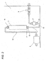
- Fig. 2 is a schematic diagram of a part of a body of the fuel cell power generation system of the first embodiment of the present invention in the vicinity of a desulfurizer.
- the fuel cell power generation system of the first embodiment includes: a fuel cell 1 configured to generate electric power by use of a fuel gas and an oxidant gas; a reformer 2 configured to subject a raw material, such as a natural gas, to steam reforming reaction, thereby producing a hydrogen-rich reformed gas; a desulfurizer 3 configured to eliminate a sulfur component from a raw gas serving as a raw material of the fuel gas containing hydrogen for power generation of the fuel cell 1 as a main component; a shutoff valve 4 configured to turn on or shut off a supply of the raw material; a booster pump 5 configured to increase the pressure of the raw gas, thereby supplying the raw gas to the reformer 2; an air blower 6 configured to supply air serving as an oxidant gas to the fuel cell 1; a flow sensor 17 disposed upstream from the desulfurizer 3 and configured to measure a flow rate of the raw material passing through the desulfurizer 3; a raw material pipe 11 that connects a desulfurizer inlet
- the controller 18 controls operation of the fuel cell power generation system, such as determining an amount of required air supplied to the fuel cell 1 according to a value of the flow rate detected by the flow sensor 17 and sending a control signal to the air blower 6.
- the shutoff valve 4, the flow sensor 17, the raw material pipe 11, the desulfurizer 3, a post-desulfurization pipe 12, the booster pump 5, the reformer 2 and the fuel cell 1 are connected in this order from an upstream side to a downstream side.
- the flow sensor 17 is disposed in the vicinity of a position immediately below the desulfurizer 3, and is connected to the desulfurizer 3 so as to communicate therewith by the raw material pipe 11 that is bent substantially in a J shape.
- the raw material pipe 11 has a raw material pipe inlet 14 that is opened upward and connected to the flow sensor 17 and a raw material pipe outlet 15 that is opened upward and connected to a desulfurizer inlet 9.
- the raw material pipe 11 is configured such that when the raw material pipe 11 is mounted to the fuel cell power generation system body 7, the raw material pipe inlet 14 connected to the flow sensor 17 is situated below the raw material pipe inlet 14 and above a trap portion 16 situated at a lowermost position of the raw material pipe 11.
- a raw material supplied from the shutoff valve 4 passes through the flow sensor 17, and a sulfur component of the raw material is eliminated by the desulfurizer 3. Subsequently, the raw material is pressurized by the booster pump 5 and supplied to the reformer 2. The raw gas is supplied to the fuel cell 1 as a hydrogen-rich fuel gas by the reforming unit 2. In the meantime, the controller 18 calculates an amount of air necessary for the fuel cell 1 according to the flow rate of raw material measured by the flow sensor 17 and sends the operation signal to the air blower 6. Reaction air serving as an oxidant gas is supplied from the air blower 6 to the fuel cell 1, whereby the fuel gas and the reaction air cause an electrochemical reaction, thereby generating electric power.
- the desulfurizer 3 eliminates sulfur contained in the raw material by use of an adsorbing phenomenon of a catalyst. Consequently, sulfur elimination capability of the desulfurizer 3 deteriorates in association with an increase in operating time. Accordingly, continuing use of the desulfurizer necessitates periodic replacement of the desulfurizer 3 with a new one. At the periodic replacement, the desulfurizer inlet 9 of the desulfurizer 3 is disconnected from the raw material pipe 11, and a desulfurizer outlet 10 is disconnected from the post-desulfurization pipe 12.
- a catalyst in the desulfurizer 3 is shaken by the microvibrations, and powder in the catalyst may come out of the desulfurizer inlet 9 provided on the lower surface of the desulfurizer 3 and enters the raw material pipe 11.
- the catalyst powder of a new desulfurizer 3 for replacement caused by transport vibrations may enter the raw material pipe 11. Further, airborne dust may enter the raw material pipe outlet 15 when the desulfurizer 3 is detached for replacement with a new desulfurizer 3.
- the catalyst powder or airborne dust entering the raw material pipe 11 is accumulated in the trap portion 16 provided at the lowest portion of the raw material pipe 11. Consequently, catalyst powder or airborne dust does not arrive at the flow sensor 17 located at an upper position with respect to the trap portion 16. Therefore, it is possible to prevent an operation failure of the flow sensor 17 caused by the entered catalyst powder or airborne dust.
- the fuel cell power generation system of the present embodiment includes: the desulfurizer 3 configured to eliminate a sulfur component from a raw gas serving as a raw material of a fuel gas containing hydrogen for power generation of the fuel cell 1 as a main component; the flow sensor 17 disposed upstream from the desulfurizer 3 and configured to measure a flow rate of raw gas passing through the desulfurizer 3; and the raw material pipe 11 having one end connected to a lower end of the desulfurizer 3 and another end connected to the flow sensor 17.
- the raw gas flows through an inside of the desulfurizer 3 in an upward direction, and the desulfurizer 3 is detachably connected to the raw material pipe 11.
- the desulfurizer 3 and the flow sensor 17 are disposed close to each other so as to be arranged side by side along a substantially vertical direction.
- the trap portion 16 configured to prevent arrival of the catalyst powder of the desulfurizer 3 or the dust entered from the one end of the raw material pipe 11 at the flow sensor 17 is disposed at a portion of the raw material pipe 11 between the one end thereof and the another end thereof.
- the trap portion 16 is configured such that side upstream from the trap portion 16 is situated above the trap portion 16.
- the trap portion 16 configured to prevent arrival of the catalyst powder of the desulfurizer 3 or dust entering from one end of the raw material pipe 11 at the flow sensor 17 is provided at a position of the raw material pipe 11 between the one end thereof and the another end thereof.
- the trap portion 16 may be formed such that side upstream from the trap portion 16 becomes higher than the trap portion 16. With this configuration, the trap portion 16 can readily be formed simply by bending the raw material pipe 11.
- the desulfurizer 3 is a part to be periodically replaced. Therefore, the desulfurizer 3 is disposed at a structural position to allow superior ease of maintenance. By disposing the flow sensor 17 in the vicinity of the position immediately below the desulfurizer 3, it becomes easy to check the flow sensor 3, whereby ease of maintenance of the flow sensor 3 is enhanced.
- the flow sensor 17 serves as an exemplified auxiliary device configured to communicate with the connection inlet provided on the lower surface of the desulfurizer 3 through the raw material pipe 11.
- another auxiliary device such as the shutoff valve 4 used in the fuel cell power generation system and a pressure sensor, is provided at the same structural location, it is also possible to prevent an operation failure of the auxiliary device caused by the catalyst powder or airborne dust.
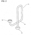
- Fig. 3 is a perspective view of a raw material pipe used in a fuel cell power generation system of a second embodiment of the present invention
- Fig. 4 is a schematic diagram of a part of a body of the fuel cell power generation system of the embodiment in the vicinity of a desulfurizer.
- the raw material pipe 11 is bent into a loop shape along the vertical direction.
- the raw material pipe 11 includes the raw material pipe inlet 14 opened downward for a connection with the flow sensor 17, the raw material pipe outlet 15 opened upward in the vertical direction for a connection with the desulfurizer inlet 9, and the trap portion 16 serving as a lowermost portion of the loop portion of the raw material pipe 11.
- the flow sensor 17 is disposed in the vicinity of a position immediately below the desulfurizer 3, and is connected to the desulfurizer 3 so as to communicate therewith by the raw material pipe 11.
- the raw material pipe 11 bent in a loop shape along the vertical direction, instead of the raw material pipe 11 substantially bent in a J shape in the first embodiment.
- the second embodiment is structurally identical with the first embodiment.
- the catalyst in the desulfurizer 3 is shaken by the microvibrations, and catalyst powder may come out of the desulfurizer inlet 9 provided on the lower surface of the desulfurizer 3, to thus enter the raw material pipe 11.
- the catalyst powder of a new desulfurizer 3 for replacement caused by transport vibrations may enter the raw material pipe 11. Further, airborne dust may enter the raw material pipe outlet 15 when the desulfurizer 3 is detached for replacement with a new desulfurizer 3.
- the raw material pipe 11 is formed in a loop shape along the vertical direction, the entered catalyst powder or airborne dust is accumulated in the trap portion 16 provided at the lowermost portion of the loop portion of the raw material pipe 11 and does not arrive at the flow sensor 17. Consequently, it is possible to prevent an operation failure of the flow sensor 17 caused by the entered catalyst powder or airborne dust.
- the flow sensor 17 can readily be disposed in the vicinity of a position immediately below the desulfurizer 3. Since the desulfurizer 3 is a part to be periodically replaced, the desulfurizer 3 is disposed at a structural position to allow superior ease of maintenance. Consequently, the flow sensor 17 disposed in the vicinity of the position immediately below the desulfurizer 3 exhibits superior ease of maintenance.
- the flow sensor 17 is likely to be affected by pressure fluctuations caused by an increase of pressure of a raw material in the booster pump 5 communicating therewith. Nevertheless, the raw material pipe 11 is shaped to have a loop shape, which results in an increase in pipe length and a buffer space. Therefore, influence of pressure fluctuations in the booster pump 5 is lowered, and the accuracy of measurement of the flow sensor 17 is enhanced, whereby stable device operation can be realized.
- the loop shape of the raw material pipe 11 is one turn. However, the number of loops may be increased, which increases the buffer space and further lowers the influence of the booster pump 5.
- the raw material pipe 11 includes at least one loop portion in the vertical direction, and the lowermost portion of the loop portion of the raw material pipe 11 functions as the trap portion 16.
- the trap portion 16 located at the lowermost portion of the loop portion of the raw material pipe 11 and does not arrive at the flow sensor 17. Consequently, it is possible to prevent an operation failure of the flow sensor 17 caused by entered catalyst powder or airborne dust.
- the flow sensor 17 can easily be disposed in the vicinity of the position immediately below the desulfurizer 3.
- the flow sensor 17 serves as an exemplified auxiliary device configured to communicate with the connection inlet provided on the lower surface of the desulfurizer 3 through the raw material pipe 11.
- another auxiliary device such as the shutoff valve 4 used in the fuel cell power generation system and a pressure sensor, is provided at the same structural location, it is also prevent an operation failure of the auxiliary device caused by the catalyst powder or airborne dust.
- Fig. 5 is a schematic diagram of a part of a body of a fuel cell power generation system of a third embodiment of the present invention in the vicinity of the desulfurizer 3.
- the third embodiment is configured such that an inner diameter of the trap portion 16 is set greater than an inner diameter of a portion the raw material pipe 11 except the trap portion 16, in the fuel cell power generation system of the first embodiment.
- the third embodiment is structurally identical with the first embodiment.
- the catalyst in the desulfurizer 3 is shaken by the microvibrations, and catalyst powder may come out of from the desulfurizer inlet 9 provided on the lower surface of the desulfurizer 3, to thus enter the raw material pipe 11.
- the catalyst powder of a new desulfurizer 3 for replacement caused by transport vibrations may enter the raw material pipe 11.
- airborne dust may enter the raw material pipe outlet 15 when the desulfurizer 3 is eliminated for replacement with a new desulfurizer 3.
- the raw material pipe 11 substantially bent in the J shape is used, and the inner diameter of the trap portion 16 situated at the lowermost portion of the raw material pipe 11 is set greater than the inner diameter of a portion of the raw material pipe 11 except the trap portion 16. Therefore, catalyst powder or airborne dust entering the raw material pipe 11 is accumulated in the trap portion 16 situated at the lowermost portion of the raw material pipe 11 and does not arrive at the flow sensor 17 disposed above the trap portion 16, whereby it is possible to prevent an operation failure of the flow sensor 17 caused by entered catalyst powder or airborne dust. Since the trap portion 16 has an inner diameter greater than the inner diameter of a portion of the raw material pipe 11 except the trap portion 16, even when the catalyst powder or airborne dust is accumulated in the trap portion 16, it hardly impedes a raw gas flow.
- the flow sensor 17 is likely to be affected by pressure fluctuations caused by an increase of pressure of the raw material in the booster pump 5 communicating therewith. Nevertheless, by increasing the inner diameter of the trap portion 16 situated at a portion of the raw material pipe 11 between the one end thereof and another end thereof, the inner volume of the trap portion 16 can be increased, and a buffer space can be increased. Therefore, influence of pressure fluctuations in the booster pump 5 is lowered, and the accuracy of measurement of the flow sensor 17 is enhanced, whereby stable device operation can be realized.
- the flow sensor 17 serves as an exemplified auxiliary device configured to communicate with the connection inlet provided on the lower surface of the desulfurizer 3 through the raw material pipe 11.
- another auxiliary device such as the shutoff valve 4 used in the fuel cell power generation system and a pressure sensor, is provided at the same structural location, it is also possible to prevent an operation failure of the auxiliary device caused by the catalyst powder or airborne dust.
- Fig. 6 is a schematic diagram of a part of a body of a fuel cell power generation system of a fourth embodiment of the present invention in the vicinity of the desulfurizer.
- the fuel cell power generation system of the fourth embodiment is configured such that in the fuel cell power generation system of the second embodiment, an inner diameter of the trap portion 16 is set greater than an inner diameter of a portion of the raw material pipe 11 except the trap portion 16.
- the third embodiment is structurally identical with the second embodiment.
- the catalyst in the desulfurizer 3 is shaken by the microvibrations, and catalyst powder may come out of the desulfurizer inlet 9 provided on the lower surface of the desulfurizer 3, to thus enter the raw material pipe 11.
- the catalyst powder of a new desulfurizer 3 for replacement caused by transport vibrations may enter the raw material pipe 11.
- airborne dust may enter the raw material pipe outlet 15 in a period during which the desulfurizer 3 is eliminated for replacement with a new desulfurizer 3.
- the raw material pipe 11 is bent in a loop shape in the vertical direction, and the inner diameter of the trap portion 16 situated at the lowermost portion of the loop portion of the raw material pipe 11 is set greater than the inner diameter of a portion the raw material pipe 11 except the trap portion 16.
- catalyst powder or airborne dust entering the raw material pipe 11 is accumulated in the trap portion 16 situated at the lowermost portion of the loop portion of the raw material pipe 11 and does not arrive at the flow sensor 17, whereby it is possible to prevent an operation failure of the flow sensor 17 caused by entered catalyst powder or airborne dust, Since the trap portion 16 has an inner diameter greater than the inner diameter of a portion of the raw material pipe 11 except the trap portion 16, even when the catalyst powder or airborne dust is accumulated in the trap portion 16, it hardly impedes a raw gas flow.
- the flow sensor 17 can readily be disposed in the vicinity of a position immediately below the desulfurizer 3. Since the desulfurizer 3 is a part to be periodically replaced, the desulfurizer 3 is disposed at a structural position to allow superior ease of maintenance. Consequently, the flow sensor 17 disposed in the vicinity of the position immediately below the desulfurizer 3 exhibits superior ease of maintenance.
- the flow sensor 17 is likely to be affected by pressure fluctuations caused by an increase of pressure of a raw material in the booster pump 5 communicating therewith. Nevertheless, by increasing the inner diameter of the trap portion 16 provided at a portion of the raw material pipe 11 between the one end thereof and another end thereof, the inner volume of the trap portion 16 can be increased, and the buffer space can also be increased. Therefore, influence of pressure fluctuations in the booster pump 5 is lowered, and the accuracy of measurement of the flow sensor 17 is enhanced, whereby stable device operation can be realized.
- the flow sensor 17 serves as an exemplified auxiliary device configured to communicate with the connection inlet provided on the lower surface of the desulfurizer 3 through the raw material pipe 11.
- another auxiliary device such as the shutoff valve 4 used in the fuel cell power generation system and a pressure sensor, is provided at the same structural location, it is also possible to prevent an operation failure of the auxiliary device caused by catalyst powder or airborne dust.
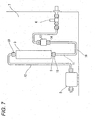
- Fig. 7 is a schematic diagram of a part of a body of a fuel cell power generation system of a fifth embodiment of the present invention in the vicinity of the desulfurizer 3.
- the fuel cell power generation system of the fifth embodiment is configured such that in the fuel cell power generation system of the first embodiment, a position of a downstream side of the flow sensor 17 is situated above a position of an upstream side of the desulfurizer 3..
- the fifth embodiment is structurally identical with the first embodiment.
- the position of the downstream side of the flow sensor 17 refers to a position of a side of a potion of the flow sensor 17 closer to the raw material pipe inlet 14 in Fig. 7 .
- the position of the upstream side of the desulfurizer 3 refers to a position of a side of the desulfurizer 3 closer to the raw material pipe outlet 15 in Fig. 7 .
- the catalyst in the desulfurizer 3 is shaken by the microvibrations, and catalyst powder may come out of the desulfurizer inlet 9 provided on the lower surface of the desulfurizer 3, to thus enter the raw material pipe 11.
- the catalyst powder of a new desulfurizer 3 for replacement caused by transport vibrations may enter the raw material pipe 11.
- airborne dust may enter the raw material pipe outlet 15 when the desulfurizer 3 is eliminated for replacement with a new desulfurizer 3.
- the raw material pipe 11 substantially bent in the J shape is used, and the position of the downstream side of the flow sensor 17 is situated above the position of the upstream side of the desulfurizer 3. Consequently, positional energy resultant of fall of catalyst powder or airborne dust in the raw material pipe 11 is insufficient for the catalyst powder or airborne dust to pass through the trap portion 16 and arrive at the flow sensor 17 situated above the trap portion 16. Therefore, it is possible to prevent an operation failure of the flow sensor 17 caused by entered catalyst powder or airborne dust.
- the flow sensor 17 serves as an exemplified auxiliary device configured to communicate with the connection inlet provided on the lower surface of the desulfurizer 3 through the raw material pipe 11.
- another auxiliary device such as the shutoff valve 4 used in the fuel cell power generation system and a pressure sensor, is provided at the same structural location, it is also possible to prevent an operation failure of the auxiliary device caused by the catalyst powder or airborne dust.
- the trap portion 16 in the raw material pipe 11 shown in Fig. 7 may be configured such that an inner diameter thereof is set larger than an inner diameter of a portion of the raw material pipe .11 except the trap portion 16, such as the trap portion 16 shown in Fig. 5 .
- positional energy resultant of fall of catalyst powder or airborne dust in the raw material pipe 11 is insufficient for the catalyst powder or airborne dust to pass through the trap portion 16 and arrive at the flow sensor 17 situated above the trap portion 16. Consequently, it is possible to prevent an operation failure of the flow sensor 17 caused by entered catalyst powder or airborne dust.
- the flow sensor 17 is likely to be affected by pressure fluctuations caused by an increase of pressure of a raw material in the booster pump 5 communicating therewith.
- the inner diameter of the trap portion 16 provided at a portion of the raw material pipe 11 between one end thereof and another end thereof, the inner volume of the trap portion 16 can be increased, and the buffer space can also be increased. Therefore, influence of pressure fluctuations in the booster pump 5 is lowered, and the accuracy of measurement of the flow sensor 17 is enhanced, whereby stable device operation can be realized.
- the trap portion prevents catalyst powder of the desulfurizer or airborne dust, which enters in the raw material pipe 11, from entering the flow sensor. Therefore, it is possible to prevent an operation failure of the flow sensor caused by entry of catalyst powder or airborne dust, whereby operation reliability of the flow sensor can be enhanced. Consequently, the present invention is useful for a fuel cell power generation system for home use in which a desulfurizer is connected to an auxiliary device used in the fuel cell power generation system, such as a flow sensor located below the desulfurizer, by a raw material pipe, and in which the desulfurizer is to be periodically replaced.
Landscapes
- Chemical & Material Sciences (AREA)
- Chemical Kinetics & Catalysis (AREA)
- Engineering & Computer Science (AREA)
- General Chemical & Material Sciences (AREA)
- Sustainable Energy (AREA)
- Sustainable Development (AREA)
- Manufacturing & Machinery (AREA)
- Electrochemistry (AREA)
- Life Sciences & Earth Sciences (AREA)
- Organic Chemistry (AREA)
- Health & Medical Sciences (AREA)
- General Health & Medical Sciences (AREA)
- Combustion & Propulsion (AREA)
- Inorganic Chemistry (AREA)
- Fuel Cell (AREA)
- Hydrogen, Water And Hydrids (AREA)
Abstract
Description
- The present invention relates to a body structure of a fuel cell power generation system configured to generate electric power by use of a fuel cell.
- There is a fuel cell power generation system disclosed in
Patent Document 1 as a related art fuel cell power generation system. The related art fuel cell power generation system disclosed inPatent Document 1 is described by reference toFig. 8. Fig. 8 shows a configuration of the related art fuel cell power generation system disclosed inPatent Document 1. - As shown in
Fig. 8 , the related art fuel cell power generation system includes a fuel cell, 1 configured to generate electric power by use of a fuel gas and an oxidant gas; areformer 2 configured to subject a raw material, such as a natural gas, to a steam reforming reaction, thereby producing a hydrogen-rich reformed gas; adesulfurizer 3 configured to eliminate a sulfur component from a raw gas serving as a raw material for a fuel gas containing hydrogen for power generation of thefuel cell 1 as a main component; ashutoff valve 4 configured to turn on or shut off a supply of the raw material; abooster pump 5 configured to increase the pressure of the raw gas, thereby supplying the raw gas to thereformer 2; and anair blower 6 configured to supply air serving as an oxidant gas to thefuel cell 1. Thedesulfurizer 3 and theshutoff valve 4 are connected by araw material pipe 11, and thedesulfurizer 3 and thebooster pump 5 are connected by apost-desulfurization pipe 12. - A configuration of a related art fuel cell power generation system including a desulfurizer is disclosed in
Patent Document 2. The configuration of the related art fuel cell power generation system including a desulfurizer disclosed inPatent Document 2 is now described by reference toFig. 9. Fig. 9 shows a part of a body configuration in the vicinity of the desulfurizer of the related art fuel cell power generation system disclosed inPatent Document 2. - As shown in
Fig. 9 , the related art fuel cell power generation system includes a fuel cell power generation system body 7 provided with an access panel 8 used for attaching or detaching thedesulfurizer 3. Thedesulfurizer 3 has a cylindrical shape, and includes adesulfurizer inlet 9 provided on a lower surface thereof and adesulfurizer outlet 10 provided on an upper surface thereof. - By reference to
Figs. 8 and9 , operation of the related art fuel cell power generation system is described. - A raw material is supplied from the
shutoff valve 4, and a sulfur component of the raw material is eliminated by thedesulfurizer 3. Subsequently, the raw material is pressurized by thebooster pump 5 and supplied to thereformer 2. The raw gas is supplied to thefuel cell 1 as a hydrogen-rich fuel gas by the reformingunit 2. In the meantime, reaction air serving as an oxidant gas is supplied from theair blower 6 to thefuel cell 1, whereby the fuel gas and the reaction air cause an electrochemical reaction, thereby generating electric power. - The
desulfurizer 3 eliminates sulfur contained in the raw material by use of an adsorbing phenomenon of a catalyst. Consequently, sulfur elimination capability of thedesulfurizer 3 deteriorates in association with an increase in operating time. Therefore, continuing use of the system necessitates periodic replacement of thedesulfurizer 3 with a new one. At the periodic replacement, thedesulfurizer 3 is replaced through the access port 8. The replacement is performed by disconnecting thedesulfurizer inlet 9 of thedesulfurizer 3 from theraw material pipe 11 and thedesulfurizer outlet 10 from thepost-desulfurization pipe 12. -
- Patent Document 1:
JP-A-2008-282572 - Patent Document 2:
JP-A-2006-140164 - However, in the above-described related-art configuration, the following phenomenon occurs. Specifically, vibrations of the
booster pump 5 are transmitted to thedesulfurizer 3 through thepost-desulfurization pipe 12, and such microvibrations shake the catalyst in thedesulfurizer 3. Especially, during the halt of the power generation system in which a raw material does not flow, powder of the catalyst comes out of thedesulfurizer outlet 9 provided on the lower surface of thedesulfurizer 3 and enters theraw material pipe 11. - In addition, at periodic replacement of the
desulfurizer 3, the catalyst powder produced in anew desulfurizer 3 for replacement by transportation vibrations may enter theraw material pipe 11. Further, when thedesulfurizer 3 is detached for replacement purpose, airborne dust may enter theraw material pipe 11 from its opening. - When the catalyst powder or airborne dust enters the
raw material pipe 11 as described above and arrives at theshutoff valve 4 communicating with theraw material pipe 11, the powder or dust enters a sliding portion of theshutoff valve 4, thereby raising a problem of occurrence of an operation failure such as an opening/losing failure of theshutoff valve 4 or occurrence of an air sealing failure caused when the catalyst powder or airborne dust adheres to a valve seat of theshutoff valve 4. - In the related art configuration, the
shutoff valve 4 serves as an auxiliary device configured to communicate with a connection inlet provided on the lower surface of thedesulfurizer 3 through theraw material pipe 11. In reality, a flow sensor configured to measure a flow rate of raw gas passing through thedesulfurizer 3 may be interposed between thedesulfurizer 3 and theshutoff valve 4. In this case, the flow sensor serves as an auxiliary device communicating with the connection inlet provided on the lower surface of thedesulfurizer 3 through theraw material pipe 11, and the catalyst powder or airborne dust may cause an operation failure in the flow sensor. - The present invention solves the problem in the related art, and an object thereof is to prevent arrival of catalyst powder or airborne dust at a flow sensor in a fuel cell power generation system including the flow sensor communicating with a connection portion provided on a lower surface of a desulfurizer through a raw material pipe, thereby enhancing operation reliability of the sensor.
- In order to accomplish the object, a fuel cell power generation system of the present invention includes: a desulfurizer configured to eliminate a sulfur component from a raw gas serving as a raw material of a fuel gas containing hydrogen for power generation of a fuel cell as a main component; a flow sensor disposed upstream from the desulfurizer and configured to measure a flow rate of the raw gas passing through the desulfurizer; and a raw material pipe having one end connected to an upstream end of the desulfurizer and another end connected to the flow sensor, wherein the raw gas flows through an inside of the desulfurizer, wherein the desulfurizer is detachably connected to the raw material pipe, and wherein a trap portion configured to prevent catalyst powder in the desulfurizer or dust, which enters from the one end of the raw material pipe, from arriving at the flow sensor is provided at a portion of the raw material pipe between the one end thereof and the another end thereof.
- With this configuration, although the catalyst powder in the desulfurizer or airborne dust enters the raw material pipe, the trap portion can prevent the catalyst powder in the desulfurizer or the airborne dust from arriving at the flow sensor.
- In the fuel cell power generation system of the present invention, a trap portion prevents catalyst powder in a desulfurizer or airborne dust entering a pipe from proceeding to a flow sensor. Therefore, it is possible to prevent an operation failure of the flow sensor caused by entry of catalyst powder or airborne dust, whereby operation reliability of the flow sensor can be enhanced.
-
-
Fig. 1 is a schematic diagram of a fuel cell power generation system of a first embodiment of the present invention. -
Fig. 2 is a schematic diagram of a part of a body of the fuel cell power generation system of the first embodiment of the present invention in the vicinity of a desulfurizer. -
Fig. 3 is a perspective view of a raw material pipe used in a fuel cell power generation system of a second embodiment of the present invention. -
Fig. 4 is a schematic diagram of a part of a body of the fuel power generation system of the second embodiment of the present invention in the vicinity of a desulfurizer. -
Fig. 5 is a schematic diagram of a part of a body of a fuel power generation system of a third embodiment of the present invention in the vicinity of a desulfurizer. -
Fig. 6 is a schematic diagram of a part of a body of a fuel power generation system of a fourth embodiment of the present invention in the vicinity of a desulfurizer. -
Fig. 7 is a schematic diagram of a part of a body of a fuel power generation system of a fifth embodiment of the present invention in the vicinity of a desulfurizer. -
Fig. 8 is a schematic diagram of a related art fuel cell power generation system. -
Fig. 9 is a schematic diagram of a part of a body of the related art fuel cell power generation system in the vicinity of a desulfurizer. - A first invention provides a fuel cell power generation system including: a desulfurizer configured to eliminate a sulfur component from a raw gas serving as a raw material of a fuel gas containing hydrogen for power generation of a fuel cell as a main component; a flow sensor disposed upstream from the desulfurizer and configured to measure a flow rate of the raw gas passing through the desulfurizer; and a raw material pipe having one end connected to an upstream end of the desulfurizer and another end connected to the flow sensor, wherein the raw gas flows through an inside of the desulfurizer, wherein the desulfurizer is detachably connected to the raw material pipe, and wherein a trap portion configured to prevent catalyst powder of the desulfurizer or dust, which enters from one end of the raw material pipe, from arriving at the flow sensor is placed at on the raw material pipe. With this configuration, a trap portion for preventing catalyst powder of the desulfurizer or dust entered from one end of the raw material pipe from arriving at the flow sensor is placed at a potion of the raw material pipe between the one end thereof and the another end thereof. By providing the trap portion, although the catalyst powder of the desulfurizer or dust enters the raw material pipe, the trap portion can prevent the catalyst powder of the desulfurizer or the dust from arriving at the flow sensor. Therefore, it is possible to prevent an operation failure of the flow sensor caused by entry of catalyst powder or airborne dust, whereby operation reliability of the flow sensor can be enhanced.
- In a second invention, the upstream side of the desulfurizer of the first Invention is situated below a downstream side of the desulfurizer. In this case, the desulfurizer is arranged along the vertical direction, and hence the raw material gas can react with most part of a catalyst. Conversely, when the desulfurizer is arranged along the horizontal direction, the catalyst is unevenly provided so as to be deflected to a lower position in the desulfurizer. Therefore, a space not containing the catalyst is formed in an upper portion in the desulfurizer. Accordingly, the raw material gas may flow into the space and be output from the desulfurizer without desulfurized. The second invention can eliminate such a possibility.
- In a third invention, a side upstream from the trap portion of the first or second invention is situated above the trap portion. Since the trap portion can be configured such that the side upstream from the trap portion is situated above the trap portion. Thus, the trap portion can readily be formed.
- A fourth invention is based on any one of the first through third inventions, wherein the desulfurizer and the flow sensor are disposed close to each other so as to be arranged side by side substantially along a vertical direction. In general, the desulfurizer is a part to be periodically replaced. Therefore, the desulfurizer is disposed at a structural position to allow superior ease of maintenance. By disposing the desulfurizer and the flow sensor close to each other so as to be arranged side by side along the vertical direction, it becomes easy to check the flow sensor and ease of maintenance of the flow sensor is enhanced.
- A fifth invention is based on any one of the first through third inventions, wherein a position of a downstream side of the flow sensor is situated above a position of the upstream side of the desulfurizer. With this configuration, it is possible to prevent a penetration of the catalyst powder or the airborne dust through the trap portion and arriving at the flow sensor caused by positional energy resultant of fall of the catalyst powder or the airborne dust.
- In a sixth invention, the raw material pipe of any one of the first through third inventions includes at least one loop portion in the vertical direction. With this configuration, a lowermost portion of the loop portion of the raw material pipe functions as a trap portion. By providing at least one loop portion in the vertical direction in the raw material pipe, entered catalyst powder or airborne dust is accumulated in the lowermost portion of the loop portion of the raw material pipe, thereby being prevented from arriving at the flow sensor. Consequently, it is possible to prevent an operation failure caused by entered catalyst powder or airborne dust.
- By forming the raw material pipe to have a loop shape, the flow sensor can readily be disposed in the vicinity of a position immediately below the desulfurizer. During operation, the flow sensor is likely to be affected by pressure fluctuations caused by an increase of pressure of a raw material in a booster pump communicating therewith. Nevertheless, the raw material pipe is shaped to have a loop shape, which results in an increase in pipe length and a buffer space. Therefore, influence of pressure fluctuations in the booster pump is lowered, and the accuracy of measurement of the flow sensor is enhanced, whereby stable device operation can be realized.
- In a seventh invention, the trap portion of any one of the first through sixth inventions has an inner diameter greater than an inner diameter of a portion of the raw material pipe except the trap portion. Since the trap portion has the inner diameter greater than the inner diameter of the portion of the raw material pipe except the trap portion, even when the catalyst powder or the airborne dust is accumulated in the trap portion, it hardly impedes a raw gas flow.
- Further, during operation, the flow sensor is likely to be affected by pressure fluctuations caused by an increase of pressure of a raw material in the booster pump communicating therewith. Nevertheless, by increasing the inner diameter of the trap portion situated at a portion of the raw material pipe between the one end thereof and another end thereof, the inner volume of the trap portion can be greater, and a buffer space can be increased. Therefore, influence of pressure fluctuations in the booster pump is lowered, and the accuracy of measurement of the flow sensor is enhanced, whereby stable device operation can be realized.
- The fuel cell power generation system according to embodiments of the present invention is described by reference to the drawings. However, the present invention is not limited by the embodiments. Further, same or similar structural elements as those described in the related art or preceding embodiments are assigned the same reference numerals, and their detailed explanations are omitted.
-
Fig. 1 is a schematic diagram of a fuel cell power generation system of a first embodiment of the present invention, andFig. 2 is a schematic diagram of a part of a body of the fuel cell power generation system of the first embodiment of the present invention in the vicinity of a desulfurizer. - As shown in
Fig. 1 , the fuel cell power generation system of the first embodiment includes: a fuel cell 1 configured to generate electric power by use of a fuel gas and an oxidant gas; a reformer 2 configured to subject a raw material, such as a natural gas, to steam reforming reaction, thereby producing a hydrogen-rich reformed gas; a desulfurizer 3 configured to eliminate a sulfur component from a raw gas serving as a raw material of the fuel gas containing hydrogen for power generation of the fuel cell 1 as a main component; a shutoff valve 4 configured to turn on or shut off a supply of the raw material; a booster pump 5 configured to increase the pressure of the raw gas, thereby supplying the raw gas to the reformer 2; an air blower 6 configured to supply air serving as an oxidant gas to the fuel cell 1; a flow sensor 17 disposed upstream from the desulfurizer 3 and configured to measure a flow rate of the raw material passing through the desulfurizer 3; a raw material pipe 11 that connects a desulfurizer inlet on a lower surface of the desulfurizer 3 to the flow sensor 17 to establish communication therebetween; and a controller 18 connected to the shutoff valve 4, the flow sensor 17, the booster pump 5 and the air blower 6 and configured to control the shutoff valve 4, the booster pump 5 and the air blower 6. - The
controller 18 controls operation of the fuel cell power generation system, such as determining an amount of required air supplied to thefuel cell 1 according to a value of the flow rate detected by theflow sensor 17 and sending a control signal to theair blower 6. Theshutoff valve 4, theflow sensor 17, theraw material pipe 11, thedesulfurizer 3, apost-desulfurization pipe 12, thebooster pump 5, thereformer 2 and thefuel cell 1 are connected in this order from an upstream side to a downstream side. - As shown in
Fig. 2 , in the fuel cell power generation system of the present embodiment, theflow sensor 17 is disposed in the vicinity of a position immediately below thedesulfurizer 3, and is connected to thedesulfurizer 3 so as to communicate therewith by theraw material pipe 11 that is bent substantially in a J shape. Theraw material pipe 11 has a rawmaterial pipe inlet 14 that is opened upward and connected to theflow sensor 17 and a rawmaterial pipe outlet 15 that is opened upward and connected to adesulfurizer inlet 9. Theraw material pipe 11 is configured such that when theraw material pipe 11 is mounted to the fuel cell power generation system body 7, the rawmaterial pipe inlet 14 connected to theflow sensor 17 is situated below the rawmaterial pipe inlet 14 and above atrap portion 16 situated at a lowermost position of theraw material pipe 11. - Operation of the fuel cell power generation system of the embodiment configured above is now described.
- A raw material supplied from the
shutoff valve 4 passes through theflow sensor 17, and a sulfur component of the raw material is eliminated by thedesulfurizer 3. Subsequently, the raw material is pressurized by thebooster pump 5 and supplied to thereformer 2. The raw gas is supplied to thefuel cell 1 as a hydrogen-rich fuel gas by the reformingunit 2. In the meantime, thecontroller 18 calculates an amount of air necessary for thefuel cell 1 according to the flow rate of raw material measured by theflow sensor 17 and sends the operation signal to theair blower 6. Reaction air serving as an oxidant gas is supplied from theair blower 6 to thefuel cell 1, whereby the fuel gas and the reaction air cause an electrochemical reaction, thereby generating electric power. - The
desulfurizer 3 eliminates sulfur contained in the raw material by use of an adsorbing phenomenon of a catalyst. Consequently, sulfur elimination capability of thedesulfurizer 3 deteriorates in association with an increase in operating time. Accordingly, continuing use of the desulfurizer necessitates periodic replacement of thedesulfurizer 3 with a new one. At the periodic replacement, thedesulfurizer inlet 9 of thedesulfurizer 3 is disconnected from theraw material pipe 11, and adesulfurizer outlet 10 is disconnected from thepost-desulfurization pipe 12. - Because of vibrations of the
booster pump 5 transmitted to thedesulfurizer 3 during operation through thepost-desulfurization pipe 12, a catalyst in thedesulfurizer 3 is shaken by the microvibrations, and powder in the catalyst may come out of thedesulfurizer inlet 9 provided on the lower surface of thedesulfurizer 3 and enters theraw material pipe 11. In addition, at the periodic replacement of thedesulfurizer 3, the catalyst powder of anew desulfurizer 3 for replacement caused by transport vibrations may enter theraw material pipe 11. Further, airborne dust may enter the rawmaterial pipe outlet 15 when thedesulfurizer 3 is detached for replacement with anew desulfurizer 3. - However, since the
raw material pipe 11 bent substantially in the J shape is used, the catalyst powder or airborne dust entering theraw material pipe 11 is accumulated in thetrap portion 16 provided at the lowest portion of theraw material pipe 11. Consequently, catalyst powder or airborne dust does not arrive at theflow sensor 17 located at an upper position with respect to thetrap portion 16. Therefore, it is possible to prevent an operation failure of theflow sensor 17 caused by the entered catalyst powder or airborne dust. - As described above, the fuel cell power generation system of the present embodiment includes: the
desulfurizer 3 configured to eliminate a sulfur component from a raw gas serving as a raw material of a fuel gas containing hydrogen for power generation of thefuel cell 1 as a main component; theflow sensor 17 disposed upstream from thedesulfurizer 3 and configured to measure a flow rate of raw gas passing through thedesulfurizer 3; and theraw material pipe 11 having one end connected to a lower end of thedesulfurizer 3 and another end connected to theflow sensor 17. In the system, the raw gas flows through an inside of thedesulfurizer 3 in an upward direction, and thedesulfurizer 3 is detachably connected to theraw material pipe 11. Thedesulfurizer 3 and theflow sensor 17 are disposed close to each other so as to be arranged side by side along a substantially vertical direction. Thetrap portion 16 configured to prevent arrival of the catalyst powder of thedesulfurizer 3 or the dust entered from the one end of theraw material pipe 11 at theflow sensor 17 is disposed at a portion of theraw material pipe 11 between the one end thereof and the another end thereof. Thetrap portion 16 is configured such that side upstream from thetrap portion 16 is situated above thetrap portion 16. - The
trap portion 16 configured to prevent arrival of the catalyst powder of thedesulfurizer 3 or dust entering from one end of theraw material pipe 11 at theflow sensor 17 is provided at a position of theraw material pipe 11 between the one end thereof and the another end thereof. With this configuration, although the catalyst powder of thedesulfurizer 3 and the dust enters theraw material pipe 11, thetrap portion 16 prevents the catalyst powder of thedesulfurizer 3 and the dust from arriving at theflow sensor 17. Therefore, it is possible to prevent an operation failure of theflow sensor 17 caused by entry of catalyst powder or airborne dust, whereby operation reliability of theflow sensor 17 can be enhanced. - The
trap portion 16 may be formed such that side upstream from thetrap portion 16 becomes higher than thetrap portion 16. With this configuration, thetrap portion 16 can readily be formed simply by bending theraw material pipe 11. - In general, the
desulfurizer 3 is a part to be periodically replaced. Therefore, thedesulfurizer 3 is disposed at a structural position to allow superior ease of maintenance. By disposing theflow sensor 17 in the vicinity of the position immediately below thedesulfurizer 3, it becomes easy to check theflow sensor 3, whereby ease of maintenance of theflow sensor 3 is enhanced. - In the embodiment, the
flow sensor 17 serves as an exemplified auxiliary device configured to communicate with the connection inlet provided on the lower surface of thedesulfurizer 3 through theraw material pipe 11. However, even when another auxiliary device, such as theshutoff valve 4 used in the fuel cell power generation system and a pressure sensor, is provided at the same structural location, it is also possible to prevent an operation failure of the auxiliary device caused by the catalyst powder or airborne dust. -
Fig. 3 is a perspective view of a raw material pipe used in a fuel cell power generation system of a second embodiment of the present invention, andFig. 4 is a schematic diagram of a part of a body of the fuel cell power generation system of the embodiment in the vicinity of a desulfurizer. - As shown in
Fig. 3 , in the fuel cell power generation system of the second embodiment, theraw material pipe 11 is bent into a loop shape along the vertical direction. Theraw material pipe 11 includes the rawmaterial pipe inlet 14 opened downward for a connection with theflow sensor 17, the rawmaterial pipe outlet 15 opened upward in the vertical direction for a connection with thedesulfurizer inlet 9, and thetrap portion 16 serving as a lowermost portion of the loop portion of theraw material pipe 11. - As shown in
Fig. 4 , in the fuel cell power generation system of the second embodiment, theflow sensor 17 is disposed in the vicinity of a position immediately below thedesulfurizer 3, and is connected to thedesulfurizer 3 so as to communicate therewith by theraw material pipe 11. - In the second embodiment, the
raw material pipe 11 bent in a loop shape along the vertical direction, instead of theraw material pipe 11 substantially bent in a J shape in the first embodiment. In other respects, the second embodiment is structurally identical with the first embodiment. - Since the fuel cell power generation system of the second embodiment is substantially identical with the fuel cell power generation system of the first embodiment in terms of operation, an explanation is given to a difference therebetween.
- Also in the fuel cell power generation system of the second embodiment, because of vibrations of the
booster pump 5 transmitted to thedesulfurizer 3 during operation through thepost-desulfurizafiion pipe 12, the catalyst in thedesulfurizer 3 is shaken by the microvibrations, and catalyst powder may come out of thedesulfurizer inlet 9 provided on the lower surface of thedesulfurizer 3, to thus enter theraw material pipe 11. In addition, at the periodic replacement of thedesulfurizer 3, the catalyst powder of anew desulfurizer 3 for replacement caused by transport vibrations may enter theraw material pipe 11. Further, airborne dust may enter the rawmaterial pipe outlet 15 when thedesulfurizer 3 is detached for replacement with anew desulfurizer 3. - However, in the fuel cell power generation system of the second embodiment, since the
raw material pipe 11 is formed in a loop shape along the vertical direction, the entered catalyst powder or airborne dust is accumulated in thetrap portion 16 provided at the lowermost portion of the loop portion of theraw material pipe 11 and does not arrive at theflow sensor 17. Consequently, it is possible to prevent an operation failure of theflow sensor 17 caused by the entered catalyst powder or airborne dust. - Since the
raw material pipe 11 is formed in a loop shape, theflow sensor 17 can readily be disposed in the vicinity of a position immediately below thedesulfurizer 3. Since thedesulfurizer 3 is a part to be periodically replaced, thedesulfurizer 3 is disposed at a structural position to allow superior ease of maintenance. Consequently, theflow sensor 17 disposed in the vicinity of the position immediately below thedesulfurizer 3 exhibits superior ease of maintenance. - During operation, the
flow sensor 17 is likely to be affected by pressure fluctuations caused by an increase of pressure of a raw material in thebooster pump 5 communicating therewith. Nevertheless, theraw material pipe 11 is shaped to have a loop shape, which results in an increase in pipe length and a buffer space. Therefore, influence of pressure fluctuations in thebooster pump 5 is lowered, and the accuracy of measurement of theflow sensor 17 is enhanced, whereby stable device operation can be realized. In the embodiment, the loop shape of theraw material pipe 11 is one turn. However, the number of loops may be increased, which increases the buffer space and further lowers the influence of thebooster pump 5. - As described above, in the fuel cell power generation system of the second embodiment, the
raw material pipe 11 includes at least one loop portion in the vertical direction, and the lowermost portion of the loop portion of theraw material pipe 11 functions as thetrap portion 16. By providing at least one loop portion in the vertical direction in theraw material pipe 11, entered catalyst powder or airborne dust is accumulated in thetrap portion 16 located at the lowermost portion of the loop portion of theraw material pipe 11 and does not arrive at theflow sensor 17. Consequently, it is possible to prevent an operation failure of theflow sensor 17 caused by entered catalyst powder or airborne dust. By forming theraw material pipe 11 to have a loop shape, theflow sensor 17 can easily be disposed in the vicinity of the position immediately below thedesulfurizer 3. - In the second embodiment, the
flow sensor 17 serves as an exemplified auxiliary device configured to communicate with the connection inlet provided on the lower surface of thedesulfurizer 3 through theraw material pipe 11. However, even when another auxiliary device, such as theshutoff valve 4 used in the fuel cell power generation system and a pressure sensor, is provided at the same structural location, it is also prevent an operation failure of the auxiliary device caused by the catalyst powder or airborne dust. -
Fig. 5 is a schematic diagram of a part of a body of a fuel cell power generation system of a third embodiment of the present invention in the vicinity of thedesulfurizer 3. - As shown in
Fig. 5 , in the fuel cell power generation system of the third embodiment is configured such that an inner diameter of thetrap portion 16 is set greater than an inner diameter of a portion theraw material pipe 11 except thetrap portion 16, in the fuel cell power generation system of the first embodiment. In other respects, the third embodiment is structurally identical with the first embodiment. - Since the fuel cell power generation system of the third embodiment is substantially identical with the fuel cell power generation system of the first embodiment in terms of operation, an explanation is given to a difference therebetween.
- Also in the fuel cell power generation system of the third embodiment, because of vibrations of the booster plump 5 transmitted to the
desulfurizer 3 during operation through thepost-desulfurization pipe 12, the catalyst in thedesulfurizer 3 is shaken by the microvibrations, and catalyst powder may come out of from thedesulfurizer inlet 9 provided on the lower surface of thedesulfurizer 3, to thus enter theraw material pipe 11. In addition, at the periodic replacement of thedesulfurizer 3, the catalyst powder of anew desulfurizer 3 for replacement caused by transport vibrations may enter theraw material pipe 11. Further, airborne dust may enter the rawmaterial pipe outlet 15 when thedesulfurizer 3 is eliminated for replacement with anew desulfurizer 3. - However, in the fuel cell power generation system of the third embodiment, the
raw material pipe 11 substantially bent in the J shape is used, and the inner diameter of thetrap portion 16 situated at the lowermost portion of theraw material pipe 11 is set greater than the inner diameter of a portion of theraw material pipe 11 except thetrap portion 16. Therefore, catalyst powder or airborne dust entering theraw material pipe 11 is accumulated in thetrap portion 16 situated at the lowermost portion of theraw material pipe 11 and does not arrive at theflow sensor 17 disposed above thetrap portion 16, whereby it is possible to prevent an operation failure of theflow sensor 17 caused by entered catalyst powder or airborne dust. Since thetrap portion 16 has an inner diameter greater than the inner diameter of a portion of theraw material pipe 11 except thetrap portion 16, even when the catalyst powder or airborne dust is accumulated in thetrap portion 16, it hardly impedes a raw gas flow. - Further, during operation, the
flow sensor 17 is likely to be affected by pressure fluctuations caused by an increase of pressure of the raw material in thebooster pump 5 communicating therewith. Nevertheless, by increasing the inner diameter of thetrap portion 16 situated at a portion of theraw material pipe 11 between the one end thereof and another end thereof, the inner volume of thetrap portion 16 can be increased, and a buffer space can be increased. Therefore, influence of pressure fluctuations in thebooster pump 5 is lowered, and the accuracy of measurement of theflow sensor 17 is enhanced, whereby stable device operation can be realized. - In the third embodiment, the
flow sensor 17 serves as an exemplified auxiliary device configured to communicate with the connection inlet provided on the lower surface of thedesulfurizer 3 through theraw material pipe 11. However, even when another auxiliary device, such as theshutoff valve 4 used in the fuel cell power generation system and a pressure sensor, is provided at the same structural location, it is also possible to prevent an operation failure of the auxiliary device caused by the catalyst powder or airborne dust. -
Fig. 6 is a schematic diagram of a part of a body of a fuel cell power generation system of a fourth embodiment of the present invention in the vicinity of the desulfurizer. - As shown in
Fig. 6 , the fuel cell power generation system of the fourth embodiment is configured such that in the fuel cell power generation system of the second embodiment, an inner diameter of thetrap portion 16 is set greater than an inner diameter of a portion of theraw material pipe 11 except thetrap portion 16. In other respects, the third embodiment is structurally identical with the second embodiment. - Since the fuel cell power generation system of the fourth embodiment is substantially identical with the fuel cell power generation system of the second embodiment in terms of operation, an explanation is given to a difference therebetween.
- Also in the fuel cell power generation system of the fourth embodiment, because of vibrations of the
booster pump 5 transmitted to thedesulfurizer 3 during operation through thepost-desulfurization pipe 12, the catalyst in thedesulfurizer 3 is shaken by the microvibrations, and catalyst powder may come out of thedesulfurizer inlet 9 provided on the lower surface of thedesulfurizer 3, to thus enter theraw material pipe 11. In addition, at the periodic replacement of thedesulfurizer 3, the catalyst powder of anew desulfurizer 3 for replacement caused by transport vibrations may enter theraw material pipe 11. Further, airborne dust may enter the rawmaterial pipe outlet 15 in a period during which thedesulfurizer 3 is eliminated for replacement with anew desulfurizer 3. - However, in the fuel cell power generation system of the fourth embodiment, the
raw material pipe 11 is bent in a loop shape in the vertical direction, and the inner diameter of thetrap portion 16 situated at the lowermost portion of the loop portion of theraw material pipe 11 is set greater than the inner diameter of a portion theraw material pipe 11 except thetrap portion 16. Therefore, catalyst powder or airborne dust entering theraw material pipe 11 is accumulated in thetrap portion 16 situated at the lowermost portion of the loop portion of theraw material pipe 11 and does not arrive at theflow sensor 17, whereby it is possible to prevent an operation failure of theflow sensor 17 caused by entered catalyst powder or airborne dust, Since thetrap portion 16 has an inner diameter greater than the inner diameter of a portion of theraw material pipe 11 except thetrap portion 16, even when the catalyst powder or airborne dust is accumulated in thetrap portion 16, it hardly impedes a raw gas flow. - Since the
raw material pipe 11 is formed in a loop shape, theflow sensor 17 can readily be disposed in the vicinity of a position immediately below thedesulfurizer 3. Since thedesulfurizer 3 is a part to be periodically replaced, thedesulfurizer 3 is disposed at a structural position to allow superior ease of maintenance. Consequently, theflow sensor 17 disposed in the vicinity of the position immediately below thedesulfurizer 3 exhibits superior ease of maintenance. - During operation, the
flow sensor 17 is likely to be affected by pressure fluctuations caused by an increase of pressure of a raw material in thebooster pump 5 communicating therewith. Nevertheless, by increasing the inner diameter of thetrap portion 16 provided at a portion of theraw material pipe 11 between the one end thereof and another end thereof, the inner volume of thetrap portion 16 can be increased, and the buffer space can also be increased. Therefore, influence of pressure fluctuations in thebooster pump 5 is lowered, and the accuracy of measurement of theflow sensor 17 is enhanced, whereby stable device operation can be realized. - In the fourth embodiment, the
flow sensor 17 serves as an exemplified auxiliary device configured to communicate with the connection inlet provided on the lower surface of thedesulfurizer 3 through theraw material pipe 11. However, even when another auxiliary device, such as theshutoff valve 4 used in the fuel cell power generation system and a pressure sensor, is provided at the same structural location, it is also possible to prevent an operation failure of the auxiliary device caused by catalyst powder or airborne dust. -
Fig. 7 is a schematic diagram of a part of a body of a fuel cell power generation system of a fifth embodiment of the present invention in the vicinity of thedesulfurizer 3. - As shown in
Fig. 7 , the fuel cell power generation system of the fifth embodiment is configured such that in the fuel cell power generation system of the first embodiment, a position of a downstream side of theflow sensor 17 is situated above a position of an upstream side of thedesulfurizer 3..In other respects, the fifth embodiment is structurally identical with the first embodiment. The position of the downstream side of theflow sensor 17 refers to a position of a side of a potion of theflow sensor 17 closer to the rawmaterial pipe inlet 14 inFig. 7 . Further, the position of the upstream side of thedesulfurizer 3 refers to a position of a side of thedesulfurizer 3 closer to the rawmaterial pipe outlet 15 inFig. 7 . - Since the fuel cell power generation system of the fifth embodiment is substantially identical with the fuel cell power generation system of the first embodiment in terms of operation, an explanation is given to a difference therebetween.
- Also in the fuel cell power generation system of the fifth embodiment, because of vibrations of the
booster pump 5 transmitted to thedesulfurizer 3 during operation through thepost-desulfurization pipe 12, the catalyst in thedesulfurizer 3 is shaken by the microvibrations, and catalyst powder may come out of thedesulfurizer inlet 9 provided on the lower surface of thedesulfurizer 3, to thus enter theraw material pipe 11. ln addition, at the periodic replacement of thedesulfurizer 3, the catalyst powder of anew desulfurizer 3 for replacement caused by transport vibrations may enter theraw material pipe 11. Further, airborne dust may enter the rawmaterial pipe outlet 15 when thedesulfurizer 3 is eliminated for replacement with anew desulfurizer 3. - However, in the fuel cell power generation system of the fifth embodiment, the
raw material pipe 11 substantially bent in the J shape is used, and the position of the downstream side of theflow sensor 17 is situated above the position of the upstream side of thedesulfurizer 3. Consequently, positional energy resultant of fall of catalyst powder or airborne dust in theraw material pipe 11 is insufficient for the catalyst powder or airborne dust to pass through thetrap portion 16 and arrive at theflow sensor 17 situated above thetrap portion 16. Therefore, it is possible to prevent an operation failure of theflow sensor 17 caused by entered catalyst powder or airborne dust. - In the fifth embodiment, the
flow sensor 17 serves as an exemplified auxiliary device configured to communicate with the connection inlet provided on the lower surface of thedesulfurizer 3 through theraw material pipe 11. However, even when another auxiliary device, such as theshutoff valve 4 used in the fuel cell power generation system and a pressure sensor, is provided at the same structural location, it is also possible to prevent an operation failure of the auxiliary device caused by the catalyst powder or airborne dust. - The
trap portion 16 in theraw material pipe 11 shown inFig. 7 may be configured such that an inner diameter thereof is set larger than an inner diameter of a portion of the raw material pipe .11 except thetrap portion 16, such as thetrap portion 16 shown inFig. 5 . Even in this case, as in the case of the fifth embodiment, positional energy resultant of fall of catalyst powder or airborne dust in theraw material pipe 11 is insufficient for the catalyst powder or airborne dust to pass through thetrap portion 16 and arrive at theflow sensor 17 situated above thetrap portion 16. Consequently, it is possible to prevent an operation failure of theflow sensor 17 caused by entered catalyst powder or airborne dust. Further, during operation, theflow sensor 17 is likely to be affected by pressure fluctuations caused by an increase of pressure of a raw material in thebooster pump 5 communicating therewith. Nevertheless, by increasing the inner diameter of thetrap portion 16 provided at a portion of theraw material pipe 11 between one end thereof and another end thereof, the inner volume of thetrap portion 16 can be increased, and the buffer space can also be increased. Therefore, influence of pressure fluctuations in thebooster pump 5 is lowered, and the accuracy of measurement of theflow sensor 17 is enhanced, whereby stable device operation can be realized. - The present patent application is based on Japanese Patent Application (Application No.
2009-96860) filed on April 13, 2009 - In the fuel cell power generation system of the present invention, the trap portion prevents catalyst powder of the desulfurizer or airborne dust, which enters in the
raw material pipe 11, from entering the flow sensor. Therefore, it is possible to prevent an operation failure of the flow sensor caused by entry of catalyst powder or airborne dust, whereby operation reliability of the flow sensor can be enhanced. Consequently, the present invention is useful for a fuel cell power generation system for home use in which a desulfurizer is connected to an auxiliary device used in the fuel cell power generation system, such as a flow sensor located below the desulfurizer, by a raw material pipe, and in which the desulfurizer is to be periodically replaced. -
- 1
- FUEL CELL
- 3
- DESULFURIZER
- 11
- RAW MATERIAL PIPE
- 16
- TRAP PORTION
- 17
- FLOW SENSOR
Claims (7)
- A fuel cell power generation system comprising:a desulfurizer configured to eliminate a sulfur component from a raw gas serving as a raw material of a fuel gas containing hydrogen for power generation of a fuel cell as a main component;a flow sensor disposed upstream from the desulfurizer and configured to measure a flow rate of the raw gas passing through the desulfurizer; anda raw material pipe having one end connected to an upstream side of the desulfurizer and another end connected to the flow sensor,wherein the raw gas flows through an inside of the desulfurizer,wherein the desulfurizer is detachably connected to the raw material pipe, andwherein a trap portion configured to prevent catalyst powder of the desulfurizer or dust, which enters from the one end of the raw material pipe, from arriving at the flow sensor is provided at a portion of the raw material pipe between the one end thereof and the another end thereof.
- The fuel cell power generation system according to claim 1,
wherein the upstream side of the desulfurizer is situated below a downstream side of the desulfurizer. - The fuel cell power generation system according to claim 1 or 2,
wherein a side upstream from the trap portion is situated above the trap portion. - The fuel cell power generation system according to any one of claims 1 to 3,
wherein the desulfurizer and the flow sensor are disposed close to each other so as to be arranged side by side substantially along a vertical direction. - The fuel cell power generation system according to any one of claims 1 to 3,
wherein a position of a downstream side of the flow sensor is situated above a position of the upstream side of the desulfurizer. - The fuel cell power generation system according to any one of claims 1 to 3,
wherein the raw material pipe comprises at least one loop portion in the vertical direction. - The fuel cell power generation system according to any one of claims 1 to 6,
wherein the trap portion has an inner diameter greater than an inner diameter of a portion of the raw material pipe except the trap portion.
Applications Claiming Priority (2)
| Application Number | Priority Date | Filing Date | Title |
|---|---|---|---|
| JP2009096860 | 2009-04-13 | ||
| PCT/JP2010/001066 WO2010119601A1 (en) | 2009-04-13 | 2010-02-18 | Fuel cell power generation system |
Publications (4)
| Publication Number | Publication Date |
|---|---|
| EP2421079A1 true EP2421079A1 (en) | 2012-02-22 |
| EP2421079A8 EP2421079A8 (en) | 2012-06-27 |
| EP2421079A4 EP2421079A4 (en) | 2013-02-20 |
| EP2421079B1 EP2421079B1 (en) | 2015-06-24 |
Family
ID=42982276
Family Applications (1)
| Application Number | Title | Priority Date | Filing Date |
|---|---|---|---|
| EP10764188.8A Active EP2421079B1 (en) | 2009-04-13 | 2010-02-18 | Fuel cell power generation system |
Country Status (3)
| Country | Link |
|---|---|
| EP (1) | EP2421079B1 (en) |
| JP (1) | JP5483295B2 (en) |
| WO (1) | WO2010119601A1 (en) |
Family Cites Families (11)
| Publication number | Priority date | Publication date | Assignee | Title |
|---|---|---|---|---|
| JP2650666B2 (en) * | 1992-08-04 | 1997-09-03 | 三菱電機株式会社 | Desulfurization device and method for replacing catalyst thereof |
| US6635372B2 (en) * | 2001-10-01 | 2003-10-21 | General Motors Corporation | Method of delivering fuel and air to a fuel cell system |
| JP2005268043A (en) * | 2004-03-18 | 2005-09-29 | Aisin Seiki Co Ltd | Fuel cell system |
| JP2006260874A (en) * | 2005-03-16 | 2006-09-28 | Ishikawajima Harima Heavy Ind Co Ltd | Fuel gas supply device for polymer electrolyte fuel cell power generator |
| JP4507955B2 (en) * | 2005-04-05 | 2010-07-21 | トヨタ自動車株式会社 | Hydrogen generator and fuel cell system |
| JP2007084621A (en) * | 2005-09-20 | 2007-04-05 | Hagio Koatsu Yoki Kk | Desulfurizing agent cartridge |
| JP2006140164A (en) | 2006-01-11 | 2006-06-01 | Toshiba Home Technology Corp | Fuel cell device |
| JP2008258023A (en) * | 2007-04-05 | 2008-10-23 | Honda Motor Co Ltd | Packaged fuel cell |
| JP2008282572A (en) | 2007-05-08 | 2008-11-20 | Toshiba Corp | Fuel cell system |
| JP4989340B2 (en) * | 2007-07-19 | 2012-08-01 | アイシン精機株式会社 | Reforming raw material supply system |
| JP5242986B2 (en) | 2007-10-16 | 2013-07-24 | 三菱レイヨン株式会社 | Thermoplastic resin composition and method for producing the same |
-
2010
- 2010-02-18 JP JP2011509180A patent/JP5483295B2/en active Active
- 2010-02-18 EP EP10764188.8A patent/EP2421079B1/en active Active
- 2010-02-18 WO PCT/JP2010/001066 patent/WO2010119601A1/en not_active Ceased
Also Published As
| Publication number | Publication date |
|---|---|
| EP2421079B1 (en) | 2015-06-24 |
| EP2421079A4 (en) | 2013-02-20 |
| EP2421079A8 (en) | 2012-06-27 |
| JP5483295B2 (en) | 2014-05-07 |
| WO2010119601A1 (en) | 2010-10-21 |
| JPWO2010119601A1 (en) | 2012-10-22 |
Similar Documents
| Publication | Publication Date | Title |
|---|---|---|
| CN101222061B (en) | Control of nitrogen fraction in a flow shifting fuel cell system | |
| JP5919374B2 (en) | Recirculation device for a fuel cell system | |
| US20090117420A1 (en) | Method for judging system condition in fuel cell system | |
| US20100183939A1 (en) | Fuel cell system | |
| US7368192B2 (en) | Method and apparatus for hydrogen detection and dilution | |
| US9029037B2 (en) | Fuel cell system with a liquid separator | |
| EP2509144A1 (en) | Power generation system | |
| CN101322268A (en) | Utilization based fuel cell monitoring and control | |
| US20040161647A1 (en) | Surge avoidance and control of a centrifugal compressor in a fuel cell system | |
| EP2769958B1 (en) | Method for operating a hydrogen generation apparatus | |
| EP2421079B1 (en) | Fuel cell power generation system | |
| JP4989340B2 (en) | Reforming raw material supply system | |
| US11158872B2 (en) | Fuel gas supply system | |
| JP5153243B2 (en) | Fuel cell device | |
| US20100261093A1 (en) | Fuel cell system | |
| EP1635414A1 (en) | Fuel cell system | |
| JP4831973B2 (en) | Fuel cell system | |
| JP5082311B2 (en) | Fuel cell system | |
| JP2007026808A (en) | Fuel cell system | |
| KR20080091633A (en) | Dispensing System of Hydrogen Station | |
| KR100818310B1 (en) | Reformer Replacement System for Hydrogen Stations | |
| CN114902459A (en) | Method for operating a fuel cell system and controller for the method | |
| JP2003217640A (en) | Fuel cell power generation system | |
| KR102475163B1 (en) | Positive Air Pressure Damper Assembly | |
| JP2016023107A (en) | Reformer |
Legal Events
| Date | Code | Title | Description |
|---|---|---|---|
| PUAI | Public reference made under article 153(3) epc to a published international application that has entered the european phase |
Free format text: ORIGINAL CODE: 0009012 |
|
| 17P | Request for examination filed |
Effective date: 20110207 |
|
| AK | Designated contracting states |
Kind code of ref document: A1 Designated state(s): AT BE BG CH CY CZ DE DK EE ES FI FR GB GR HR HU IE IS IT LI LT LU LV MC MK MT NL NO PL PT RO SE SI SK SM TR |
|
| RIN1 | Information on inventor provided before grant (corrected) |
Inventor name: SANO, HIDEHARU Inventor name: TAGUCHI, KIYOSHI |
|
| DAX | Request for extension of the european patent (deleted) | ||
| A4 | Supplementary search report drawn up and despatched |
Effective date: 20130121 |
|
| RIC1 | Information provided on ipc code assigned before grant |
Ipc: C01B 3/38 20060101ALI20130115BHEP Ipc: H01M 8/04 20060101AFI20130115BHEP |
|
| 17Q | First examination report despatched |
Effective date: 20140114 |
|
| RIC1 | Information provided on ipc code assigned before grant |
Ipc: C01B 3/34 20060101ALI20141103BHEP Ipc: H01M 8/04 20060101AFI20141103BHEP Ipc: H01M 8/06 20060101ALI20141103BHEP |
|
| GRAP | Despatch of communication of intention to grant a patent |
Free format text: ORIGINAL CODE: EPIDOSNIGR1 |
|
| INTG | Intention to grant announced |
Effective date: 20150112 |
|
| RAP1 | Party data changed (applicant data changed or rights of an application transferred) |
Owner name: PANASONIC INTELLECTUAL PROPERTY MANAGEMENT CO., LT |
|
| GRAS | Grant fee paid |
Free format text: ORIGINAL CODE: EPIDOSNIGR3 |
|
| GRAA | (expected) grant |
Free format text: ORIGINAL CODE: 0009210 |
|
| AK | Designated contracting states |
Kind code of ref document: B1 Designated state(s): AT BE BG CH CY CZ DE DK EE ES FI FR GB GR HR HU IE IS IT LI LT LU LV MC MK MT NL NO PL PT RO SE SI SK SM TR |
|
| REG | Reference to a national code |
Ref country code: GB Ref legal event code: FG4D |
|
| REG | Reference to a national code |
Ref country code: CH Ref legal event code: EP |
|
| REG | Reference to a national code |
Ref country code: AT Ref legal event code: REF Ref document number: 733265 Country of ref document: AT Kind code of ref document: T Effective date: 20150715 |
|
| REG | Reference to a national code |
Ref country code: IE Ref legal event code: FG4D |
|
| REG | Reference to a national code |
Ref country code: DE Ref legal event code: R096 Ref document number: 602010025445 Country of ref document: DE |
|
| PG25 | Lapsed in a contracting state [announced via postgrant information from national office to epo] |
Ref country code: LT Free format text: LAPSE BECAUSE OF FAILURE TO SUBMIT A TRANSLATION OF THE DESCRIPTION OR TO PAY THE FEE WITHIN THE PRESCRIBED TIME-LIMIT Effective date: 20150624 Ref country code: NO Free format text: LAPSE BECAUSE OF FAILURE TO SUBMIT A TRANSLATION OF THE DESCRIPTION OR TO PAY THE FEE WITHIN THE PRESCRIBED TIME-LIMIT Effective date: 20150924 Ref country code: FI Free format text: LAPSE BECAUSE OF FAILURE TO SUBMIT A TRANSLATION OF THE DESCRIPTION OR TO PAY THE FEE WITHIN THE PRESCRIBED TIME-LIMIT Effective date: 20150624 Ref country code: HR Free format text: LAPSE BECAUSE OF FAILURE TO SUBMIT A TRANSLATION OF THE DESCRIPTION OR TO PAY THE FEE WITHIN THE PRESCRIBED TIME-LIMIT Effective date: 20150624 |
|
| REG | Reference to a national code |
Ref country code: AT Ref legal event code: MK05 Ref document number: 733265 Country of ref document: AT Kind code of ref document: T Effective date: 20150624 |
|
| REG | Reference to a national code |
Ref country code: LT Ref legal event code: MG4D |
|
| PG25 | Lapsed in a contracting state [announced via postgrant information from national office to epo] |
Ref country code: GR Free format text: LAPSE BECAUSE OF FAILURE TO SUBMIT A TRANSLATION OF THE DESCRIPTION OR TO PAY THE FEE WITHIN THE PRESCRIBED TIME-LIMIT Effective date: 20150925 Ref country code: LV Free format text: LAPSE BECAUSE OF FAILURE TO SUBMIT A TRANSLATION OF THE DESCRIPTION OR TO PAY THE FEE WITHIN THE PRESCRIBED TIME-LIMIT Effective date: 20150624 Ref country code: BG Free format text: LAPSE BECAUSE OF FAILURE TO SUBMIT A TRANSLATION OF THE DESCRIPTION OR TO PAY THE FEE WITHIN THE PRESCRIBED TIME-LIMIT Effective date: 20150924 |
|
| REG | Reference to a national code |
Ref country code: NL Ref legal event code: MP Effective date: 20150624 |
|
| PG25 | Lapsed in a contracting state [announced via postgrant information from national office to epo] |
Ref country code: EE Free format text: LAPSE BECAUSE OF FAILURE TO SUBMIT A TRANSLATION OF THE DESCRIPTION OR TO PAY THE FEE WITHIN THE PRESCRIBED TIME-LIMIT Effective date: 20150624 |
|
| REG | Reference to a national code |
Ref country code: FR Ref legal event code: PLFP Year of fee payment: 7 |
|
| PG25 | Lapsed in a contracting state [announced via postgrant information from national office to epo] |
Ref country code: IS Free format text: LAPSE BECAUSE OF FAILURE TO SUBMIT A TRANSLATION OF THE DESCRIPTION OR TO PAY THE FEE WITHIN THE PRESCRIBED TIME-LIMIT Effective date: 20151024 Ref country code: CZ Free format text: LAPSE BECAUSE OF FAILURE TO SUBMIT A TRANSLATION OF THE DESCRIPTION OR TO PAY THE FEE WITHIN THE PRESCRIBED TIME-LIMIT Effective date: 20150624 Ref country code: RO Free format text: LAPSE BECAUSE OF NON-PAYMENT OF DUE FEES Effective date: 20150624 Ref country code: PT Free format text: LAPSE BECAUSE OF FAILURE TO SUBMIT A TRANSLATION OF THE DESCRIPTION OR TO PAY THE FEE WITHIN THE PRESCRIBED TIME-LIMIT Effective date: 20151026 Ref country code: SK Free format text: LAPSE BECAUSE OF FAILURE TO SUBMIT A TRANSLATION OF THE DESCRIPTION OR TO PAY THE FEE WITHIN THE PRESCRIBED TIME-LIMIT Effective date: 20150624 Ref country code: AT Free format text: LAPSE BECAUSE OF FAILURE TO SUBMIT A TRANSLATION OF THE DESCRIPTION OR TO PAY THE FEE WITHIN THE PRESCRIBED TIME-LIMIT Effective date: 20150624 Ref country code: ES Free format text: LAPSE BECAUSE OF FAILURE TO SUBMIT A TRANSLATION OF THE DESCRIPTION OR TO PAY THE FEE WITHIN THE PRESCRIBED TIME-LIMIT Effective date: 20150624 Ref country code: PL Free format text: LAPSE BECAUSE OF FAILURE TO SUBMIT A TRANSLATION OF THE DESCRIPTION OR TO PAY THE FEE WITHIN THE PRESCRIBED TIME-LIMIT Effective date: 20150624 |
|
| REG | Reference to a national code |
Ref country code: DE Ref legal event code: R097 Ref document number: 602010025445 Country of ref document: DE |
|
| PG25 | Lapsed in a contracting state [announced via postgrant information from national office to epo] |
Ref country code: IT Free format text: LAPSE BECAUSE OF FAILURE TO SUBMIT A TRANSLATION OF THE DESCRIPTION OR TO PAY THE FEE WITHIN THE PRESCRIBED TIME-LIMIT Effective date: 20150624 Ref country code: DK Free format text: LAPSE BECAUSE OF FAILURE TO SUBMIT A TRANSLATION OF THE DESCRIPTION OR TO PAY THE FEE WITHIN THE PRESCRIBED TIME-LIMIT Effective date: 20150624 |
|
| PLBE | No opposition filed within time limit |
Free format text: ORIGINAL CODE: 0009261 |
|
| STAA | Information on the status of an ep patent application or granted ep patent |
Free format text: STATUS: NO OPPOSITION FILED WITHIN TIME LIMIT |
|
| PG25 | Lapsed in a contracting state [announced via postgrant information from national office to epo] |
Ref country code: BE Free format text: LAPSE BECAUSE OF NON-PAYMENT OF DUE FEES Effective date: 20160229 |
|
| 26N | No opposition filed |
Effective date: 20160329 |
|
| PG25 | Lapsed in a contracting state [announced via postgrant information from national office to epo] |
Ref country code: SI Free format text: LAPSE BECAUSE OF FAILURE TO SUBMIT A TRANSLATION OF THE DESCRIPTION OR TO PAY THE FEE WITHIN THE PRESCRIBED TIME-LIMIT Effective date: 20150624 |
|
| PG25 | Lapsed in a contracting state [announced via postgrant information from national office to epo] |
Ref country code: MC Free format text: LAPSE BECAUSE OF FAILURE TO SUBMIT A TRANSLATION OF THE DESCRIPTION OR TO PAY THE FEE WITHIN THE PRESCRIBED TIME-LIMIT Effective date: 20150624 Ref country code: LU Free format text: LAPSE BECAUSE OF FAILURE TO SUBMIT A TRANSLATION OF THE DESCRIPTION OR TO PAY THE FEE WITHIN THE PRESCRIBED TIME-LIMIT Effective date: 20160218 |
|
| REG | Reference to a national code |
Ref country code: CH Ref legal event code: PL |
|
| PG25 | Lapsed in a contracting state [announced via postgrant information from national office to epo] |
Ref country code: CH Free format text: LAPSE BECAUSE OF NON-PAYMENT OF DUE FEES Effective date: 20160229 Ref country code: LI Free format text: LAPSE BECAUSE OF NON-PAYMENT OF DUE FEES Effective date: 20160229 |
|
| REG | Reference to a national code |
Ref country code: IE Ref legal event code: MM4A |
|
| PG25 | Lapsed in a contracting state [announced via postgrant information from national office to epo] |
Ref country code: BE Free format text: LAPSE BECAUSE OF FAILURE TO SUBMIT A TRANSLATION OF THE DESCRIPTION OR TO PAY THE FEE WITHIN THE PRESCRIBED TIME-LIMIT Effective date: 20150624 |
|
| PG25 | Lapsed in a contracting state [announced via postgrant information from national office to epo] |
Ref country code: IE Free format text: LAPSE BECAUSE OF NON-PAYMENT OF DUE FEES Effective date: 20160218 |
|
| REG | Reference to a national code |
Ref country code: FR Ref legal event code: PLFP Year of fee payment: 8 |
|
| PG25 | Lapsed in a contracting state [announced via postgrant information from national office to epo] |
Ref country code: SE Free format text: LAPSE BECAUSE OF FAILURE TO SUBMIT A TRANSLATION OF THE DESCRIPTION OR TO PAY THE FEE WITHIN THE PRESCRIBED TIME-LIMIT Effective date: 20150624 Ref country code: NL Free format text: LAPSE BECAUSE OF FAILURE TO SUBMIT A TRANSLATION OF THE DESCRIPTION OR TO PAY THE FEE WITHIN THE PRESCRIBED TIME-LIMIT Effective date: 20150624 |
|
| PG25 | Lapsed in a contracting state [announced via postgrant information from national office to epo] |
Ref country code: MT Free format text: LAPSE BECAUSE OF FAILURE TO SUBMIT A TRANSLATION OF THE DESCRIPTION OR TO PAY THE FEE WITHIN THE PRESCRIBED TIME-LIMIT Effective date: 20150624 |
|
| REG | Reference to a national code |
Ref country code: FR Ref legal event code: PLFP Year of fee payment: 9 |
|
| PG25 | Lapsed in a contracting state [announced via postgrant information from national office to epo] |
Ref country code: HU Free format text: LAPSE BECAUSE OF FAILURE TO SUBMIT A TRANSLATION OF THE DESCRIPTION OR TO PAY THE FEE WITHIN THE PRESCRIBED TIME-LIMIT; INVALID AB INITIO Effective date: 20100218 Ref country code: CY Free format text: LAPSE BECAUSE OF FAILURE TO SUBMIT A TRANSLATION OF THE DESCRIPTION OR TO PAY THE FEE WITHIN THE PRESCRIBED TIME-LIMIT Effective date: 20150624 Ref country code: SM Free format text: LAPSE BECAUSE OF FAILURE TO SUBMIT A TRANSLATION OF THE DESCRIPTION OR TO PAY THE FEE WITHIN THE PRESCRIBED TIME-LIMIT Effective date: 20150624 |
|
| PG25 | Lapsed in a contracting state [announced via postgrant information from national office to epo] |
Ref country code: MK Free format text: LAPSE BECAUSE OF FAILURE TO SUBMIT A TRANSLATION OF THE DESCRIPTION OR TO PAY THE FEE WITHIN THE PRESCRIBED TIME-LIMIT Effective date: 20150624 Ref country code: MT Free format text: LAPSE BECAUSE OF FAILURE TO SUBMIT A TRANSLATION OF THE DESCRIPTION OR TO PAY THE FEE WITHIN THE PRESCRIBED TIME-LIMIT Effective date: 20160229 Ref country code: TR Free format text: LAPSE BECAUSE OF FAILURE TO SUBMIT A TRANSLATION OF THE DESCRIPTION OR TO PAY THE FEE WITHIN THE PRESCRIBED TIME-LIMIT Effective date: 20150624 |
|
| PGFP | Annual fee paid to national office [announced via postgrant information from national office to epo] |
Ref country code: DE Payment date: 20250218 Year of fee payment: 16 |
|
| PGFP | Annual fee paid to national office [announced via postgrant information from national office to epo] |
Ref country code: FR Payment date: 20250221 Year of fee payment: 16 |
|
| PGFP | Annual fee paid to national office [announced via postgrant information from national office to epo] |
Ref country code: GB Payment date: 20250219 Year of fee payment: 16 |