EP2420772A2 - Kühlkopf für eine Kühlanlage - Google Patents
Kühlkopf für eine Kühlanlage Download PDFInfo
- Publication number
- EP2420772A2 EP2420772A2 EP11450090A EP11450090A EP2420772A2 EP 2420772 A2 EP2420772 A2 EP 2420772A2 EP 11450090 A EP11450090 A EP 11450090A EP 11450090 A EP11450090 A EP 11450090A EP 2420772 A2 EP2420772 A2 EP 2420772A2
- Authority
- EP
- European Patent Office
- Prior art keywords
- cooling
- cooling head
- connecting lines
- coolant
- vacuum
- Prior art date
- Legal status (The legal status is an assumption and is not a legal conclusion. Google has not performed a legal analysis and makes no representation as to the accuracy of the status listed.)
- Granted
Links
Images

Classifications
-
- F—MECHANICAL ENGINEERING; LIGHTING; HEATING; WEAPONS; BLASTING
- F25—REFRIGERATION OR COOLING; COMBINED HEATING AND REFRIGERATION SYSTEMS; HEAT PUMP SYSTEMS; MANUFACTURE OR STORAGE OF ICE; LIQUEFACTION SOLIDIFICATION OF GASES
- F25D—REFRIGERATORS; COLD ROOMS; ICE-BOXES; COOLING OR FREEZING APPARATUS NOT OTHERWISE PROVIDED FOR
- F25D19/00—Arrangement or mounting of refrigeration units with respect to devices or objects to be refrigerated, e.g. infrared detectors
-
- F—MECHANICAL ENGINEERING; LIGHTING; HEATING; WEAPONS; BLASTING
- F25—REFRIGERATION OR COOLING; COMBINED HEATING AND REFRIGERATION SYSTEMS; HEAT PUMP SYSTEMS; MANUFACTURE OR STORAGE OF ICE; LIQUEFACTION SOLIDIFICATION OF GASES
- F25B—REFRIGERATION MACHINES, PLANTS OR SYSTEMS; COMBINED HEATING AND REFRIGERATION SYSTEMS; HEAT PUMP SYSTEMS
- F25B9/00—Compression machines, plants or systems, in which the refrigerant is air or other gas of low boiling point
- F25B9/002—Compression machines, plants or systems, in which the refrigerant is air or other gas of low boiling point characterised by the refrigerant
- F25B9/006—Compression machines, plants or systems, in which the refrigerant is air or other gas of low boiling point characterised by the refrigerant the refrigerant containing more than one component
-
- F—MECHANICAL ENGINEERING; LIGHTING; HEATING; WEAPONS; BLASTING
- F25—REFRIGERATION OR COOLING; COMBINED HEATING AND REFRIGERATION SYSTEMS; HEAT PUMP SYSTEMS; MANUFACTURE OR STORAGE OF ICE; LIQUEFACTION SOLIDIFICATION OF GASES
- F25B—REFRIGERATION MACHINES, PLANTS OR SYSTEMS; COMBINED HEATING AND REFRIGERATION SYSTEMS; HEAT PUMP SYSTEMS
- F25B9/00—Compression machines, plants or systems, in which the refrigerant is air or other gas of low boiling point
- F25B9/02—Compression machines, plants or systems, in which the refrigerant is air or other gas of low boiling point using Joule-Thompson effect; using vortex effect
-
- F—MECHANICAL ENGINEERING; LIGHTING; HEATING; WEAPONS; BLASTING
- F25—REFRIGERATION OR COOLING; COMBINED HEATING AND REFRIGERATION SYSTEMS; HEAT PUMP SYSTEMS; MANUFACTURE OR STORAGE OF ICE; LIQUEFACTION SOLIDIFICATION OF GASES
- F25B—REFRIGERATION MACHINES, PLANTS OR SYSTEMS; COMBINED HEATING AND REFRIGERATION SYSTEMS; HEAT PUMP SYSTEMS
- F25B2400/00—Component parts or details not otherwise provided for in this subclass
- F25B2400/12—Inflammable refrigerants
-
- F—MECHANICAL ENGINEERING; LIGHTING; HEATING; WEAPONS; BLASTING
- F25—REFRIGERATION OR COOLING; COMBINED HEATING AND REFRIGERATION SYSTEMS; HEAT PUMP SYSTEMS; MANUFACTURE OR STORAGE OF ICE; LIQUEFACTION SOLIDIFICATION OF GASES
- F25D—REFRIGERATORS; COLD ROOMS; ICE-BOXES; COOLING OR FREEZING APPARATUS NOT OTHERWISE PROVIDED FOR
- F25D2201/00—Insulation
- F25D2201/10—Insulation with respect to heat
- F25D2201/14—Insulation with respect to heat using subatmospheric pressure
Definitions
- the invention relates to a cooling head for a cooling system for cooling objects to semi-cryogenic temperatures of 283K to 4K with insulation means for insulating the cooling head, wherein the insulation means of the cooling head are formed by a vacuum chamber in which the cooling head is arranged, and with connecting lines connected to the cooling head for supplying and returning a cooled in a cooling unit to preferably semi-cryogenic or cryogenic temperatures coolant to or from the cooling head, wherein insulating means are provided for insulating the connecting lines.
- the invention further relates to a cooling device with such a cooling head.
- cooling capacity in vacuum chambers is required.
- a coolant for example by piping in the vacuum chamber to selectively targeted a place in the vacuum chamber to cool (eg on a copper plate).
- the coolant may be a coolant (eg glycol) or a refrigerant eg R404A, R410A, propane (R290), methane (R50), liquid nitrogen (R728), liquid argon (R740) or liquid helium.
- the temperature range of the coolant is approx. Between 283K - 4K. In this case, both the cooling supply line and the vacuum feedthrough into the chamber are a decisive element in order not to lose cooling power along the path from the cooling reservoir or the cooling machine into the vacuum chamber.
- a vacuum chamber design may not be useful under some circumstances.
- a refrigeration unit eg a closed-circuit compression refrigeration machine Circuit, a Closed Loop Chiller, a Mixed Gas Joule Thomson Chiller, ect.
- the connecting lines are often with elastomers such as Armaflex ® (up to 77 K resistant), or by means of vacuum insulation isolated.
- elastomers such as Armaflex ® (up to 77 K resistant), or by means of vacuum insulation isolated.
- problems such as insulation losses, condensation and the rigidity of the insulation material are to be mentioned.
- the connecting lines are becoming increasingly inflexible at lower temperatures. When bent in the cooled state, this even leads to the breakage of the insulation material.
- a vacuum insulation is to be mentioned as a disadvantage that the cost is very high and also the problem of the vacuum implementation is not solved as in the first case.
- the vacuum supply line usually consists of a tube-in-tube pipe, in which there is a vacuum in the outer tube; Inside the tube, the coolant is transported. The freezing or icing of the vacuum flange or the entire vacuum chamber and the occurrence of condensation are still a problem when not suitable vacuum feedthrough.
- chillers (Gifford-McMahon Chiller, Pulse Tube Chillers, Mixed Gases Joule Thomson Chiller ect.) That solve the targeted introduction of cold in a vacuum chamber thereby, a part of the production process (heat exchanger, regenerator, etc.) for to carry out the cold directly in the vacuum chamber.
- the connections supply and discharge to the respective compressor unit of the device
- the disadvantage is that the devices require a large vacuum chamber, which is undesirable or even unusable for many processes.
- the invention therefore aims to improve a cooling head and a cooling device such that a cooling of an object efficiently to the lowest possible semi-cryogenic or cryogenic temperatures succeeds and the losses during transport of the coolant are kept as low as possible, the vacuum chamber should be designed as small and handy as possible.
- a cooling head of the type mentioned above according to the invention substantially further developed such that the insulation means of the connecting lines are formed by a vacuum insulation, wherein the vacuum chamber and the vacuum insulation of the connecting lines are directly related and with a common negative pressure source can be connected, and wherein the connecting lines are led out at the end facing away from the cooling head of the vacuum insulation.
- the invention uses the vacuum system of the vacuum chamber to suitably the refrigerant on the transport between the vacuum chamber or to isolate the cooling head and the cooling reservoir and to make a vacuum feedthrough.
- the vacuum chamber itself is located on the connecting lines mounted cooling head (eg copper) through which the refrigerant (eg liquid nitrogen) is coming from the connecting lines coming.
- the existing vacuum chamber is expanded by the relatively small volume of the vacuum insulation of the connecting lines and at the same time created a vacuum connection between the vacuum insulation of the connecting lines and the vacuum chamber.
- the vacuum chamber has a passage for the connecting lines, which is designed such that the cavity of the vacuum insulation of the connecting lines is in communication with the interior of the vacuum chamber.
- the refrigerant-carrying pipe is appropriately led out of the vacuum insulation, as well as vacuum-insulated pipes known from the prior art. It is particularly important to pay attention to the thermal conductivity of the cladding tube of the vacuum insulation and the heat transfer surface. A good vacuum welding during the transition is also important. This transition, which should cause low heat transfer losses, can be further protected by conventional insulation against condensation or ice.
- the vacuum insulation comprises an enveloping tube surrounding the connecting lines to form a preferably substantially annular cavity.
- the buffer tube can be flexible as well as the connecting lines.
- the embodiment is preferably designed such that at least one spacer is arranged in the hollow space between the connecting lines and the enveloping hose.
- the spacer has a corrugated outer and inner contour, it is ensured that between spacers on the one hand and the buffer tube and the connecting lines on the other hand only point or linear contacts arise, due to such Hertzian contacts the heat input can be further reduced from the outside.
- a particularly simple structure is achieved according to a preferred embodiment, when the common vacuum source is connected to the vacuum chamber.
- a surrounding surrounding the implementation in particular tubular spacer is arranged, which defines the distance between the cooling head and the inner wall of the vacuum chamber, wherein the spacer has radial openings, so that the interior of the vacuum chamber is in communication with the cavity of the vacuum insulation of the connecting lines.
- a cooling device comprising a cooling unit with means for cooling a coolant to preferably semi-cryogenic or cryogenic temperatures and a cooling unit separate cooling head connected by means connected to the cooling head flexible connecting lines for feeding and returning the Coolant is connected to the cooling unit.
- a cooling unit with means for cooling a coolant to preferably semi-cryogenic or cryogenic temperatures
- a cooling unit separate cooling head connected by means connected to the cooling head flexible connecting lines for feeding and returning the Coolant is connected to the cooling unit.
- a so-called mixed gas joule Thomson refrigeration unit is used, for example, from the EP 650674 A1 has become known.
- the invention provides that a cooling unit is provided for cooling the coolant, which has a compressor for compressing the coolant to which the coolant is supplied in the gaseous state and from which the coolant exits in compressed gaseous state, and a compressor connected downstream Aftercooler comprises, from which the mostly gaseous refrigerant is fed to a countercurrent heat exchanger comprising a supply and a return line, which are arranged such that the compressed refrigerant in the supply line is liquefied by heating the flowing through the return line expanded refrigerant, wherein the connecting lines to the Supply and return line are connected, so that the cooling head is flowed through by the coolant in which the coolant evaporates.
- the compressor, the aftercooler and the countercurrent heat exchanger are arranged together in a stand unit whose housing has a passage for connecting the countercurrent heat exchanger with the vacuum chamber connecting lines.
- radiator with the interposition of a throttle element, is connected to the supply line of the countercurrent heat exchanger so that the necessary pressure reduction of the refrigerant takes place and the liquefied coolant can evaporate in the refrigeration head.
- connecting line connecting the supply line of the countercurrent heat exchanger with the cooling head forms the throttle element.
- the coolant preferably comprises butane and / or isobutane and / or propane and / or propene and / or ethyne and / or ethane and / or ethene and / or methane and / or argon and / or nitrogen.
- FIG.1 a closed cooling circuit with a cooling unit and a cooling head
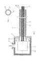
- Fig.2 a sectional view of the cooling head with the connecting lines
- Figure 3 a section along the line III-III of Fig.2 ,
- the cooling circuit shown is usually referred to as the mixed gas joule Thomson cooling process and is for example in the document EP 650574 A1 described.
- the cooling circuit comprises a compressor 1 for compressing the gaseously supplied refrigerant in 2.
- the refrigerant may be, for example, a gas mixture consisting of propane, ethane, methane and nitrogen.
- the compressed refrigerant is fed via a line 3 to an oil separator 4, with which the possibly in the compressor 1 with the refrigerant mixing oil is separated.
- the oil purified by the oil is then fed to an aftercooler 5, in which the heat supplied to the compressor 1 is removed from the refrigerant.
- the cooled, compressed, but still mostly gaseous refrigerant is then fed via a line 6 to a countercurrent heat exchanger 7, in which the coolant flowing through the refrigerant supply line 8 is cooled and liquefied by the refrigerant flowing in the refrigerant return line 9.
- the refrigerant supply line 8 and the refrigerant return line 9 may in practice be several meters long and often become helical or spirally wound to achieve a certain compactness of the heat flow heat exchanger.
- the liquefied refrigerant is depressurized via a throttle 10, so that the refrigerant in the cooling head 11 evaporate and thereby escape the environment evaporation heat.
- the cooling head 11 is flowed through by the coolant and is therefore designed, for example, as a hollow cylinder.
- the flowing back from the cooling head 11 refrigerant is heated in countercurrent heat exchanger 7 in the sequence up to room temperature, wherein the refluxing refrigerant cools the flowing refrigerant.
- the cooling head 11 is therefore made of a thermally conductive material such as copper.
- the cooling head 11 is connected via connecting lines 13 and 14 to the counterflow heat exchanger 7, so that the cooling unit 15 and the cooling head 11 arranged in a vacuum chamber 16 can be realized as separate structural units.
- the inventive construction makes it necessary that the cooled and liquefied in the heat exchanger 7 refrigerant is transported via the connecting lines 13 and 14 over a more or less long distance, so that a sufficient insulation of the connecting lines must be ensured.
- the cooling head with vacuum chamber and the connecting lines are shown in detail.
- the connecting lines 13 and 14 have a vacuum insulation 17 whose evacuated interior is in communication with the interior of the vacuum chamber 16.
- the connecting lines 13 and 14 may be formed as flexible tubes to improve the handling.
- the Vacuum insulation 17 of the connecting line has a flexible Hüllschlauch 18, which may be formed for example as a stainless steel corrugated tube, which preferably has a steel jacket.
- spacers 19 may be arranged, which may also be made flexible.
- the spacers 19 preferably have a corrugated outer contour, so that the heat transfer is minimized due to the line contacts achieved with the cladding tube 18 or the connecting lines 13 and 14.
- the spacer 19 thus serves the mechanical and thus thermal decoupling of the connecting lines 13 and 14 to the cladding tube 18. It should be sufficiently flexible, temperature stable, resistant to aging and degassing (eg Teflon, plastic, stainless steel).
- Teflon, plastic, stainless steel eg Teflon, plastic, stainless steel.
- the connecting lines 13 and 14 are led out of the vacuum insulation 17.
- Low thermal losses at the transition point 20 should be taken into account. This can be achieved by materials with low thermal conductivity and a low transition cross-section (eg stainless steel).
- the interface 20 may be protected by conventional thermal insulation materials (eg, foamed polystyrene, elastomers).
- the connecting lines 13 and 14 may be thermally coupled.
- the connecting lines 13 and 14 can alternatively be guided into each other.
- the coolant can experience a reduction in pressure along the supply line, so that the refrigerant evaporates in the cooling head as in compression refrigerating machines and heat is dissipated.
- the supply line is immediately throttle body.
- the vacuum insulation 17 is connected to a vacuum flange 21, through which the connecting lines 13 and 14 are passed and fed to the cooling head 11.
- a spacer 22 is disposed between the cooling head 11 and the vacuum flange 21, which may for example consist of Teflon, ceramic or stainless steel and ausgasungsbestopathy, low temperature suitable, should be resistant to embrittlement and aging. It is important to ensure a sufficient thermal decoupling of the spacer 22 from the vacuum flange 21 and a good atmospheric permeability to the cladding tube 18.
- the spacer 22 has a plurality of radial openings 24, so that the evacuated interior of the vacuum insulation of the connecting lines with the evacuated interior of the vacuum chamber 16 is in a conductive connection.
- a flange for connection to a vacuum pump is indicated at 23.
- the cooling head When the cooling head flows through coolant evenly and when the cooling head is mechanically stabilized by means of spacers, the cooling head is extremely low in vibration.
- Typical applications for the invention are the cooling of high-power laser amplifiers and various cooling tasks in analytical chemistry, in the field of superconductivity, astronomy and in general in research and development as well as in medical diagnostics.
Landscapes
- Engineering & Computer Science (AREA)
- Physics & Mathematics (AREA)
- Mechanical Engineering (AREA)
- Thermal Sciences (AREA)
- General Engineering & Computer Science (AREA)
- Chemical & Material Sciences (AREA)
- Combustion & Propulsion (AREA)
- Thermal Insulation (AREA)
Abstract
Description
- Die Erfindung betrifft einen Kühlkopf für eine Kühlanlage zum Kühlen von Objekten auf semi-kryogen bzw. kryogene Temperaturen von 283K bis 4K mit Isolationsmitteln zum Isolieren des Kühlkopfes, wobei die Isolationsmittel des Kühlkopfes von einer Vakuumkammer gebildet sind, in welcher der Kühlkopf angeordnet ist, und mit an den Kühlkopf angeschlossenen Verbindungsleitungen zum Zu- und Rückführen eines in einem Kühlaggregat auf bevorzugt semi-kryogen bzw. kryogene Temperaturen abgekühlten Kühlmittels zum bzw. vom Kühlkopf, wobei Isolationsmittel zum Isolieren der Verbindungsleitungen vorgesehen sind. Die Erfindung betrifft weiters eine Kühlvorrichtung mit einem derartigen Kühlkopf.
- Für viele Anwendungen wird Kühlleistung in Vakuumkammern benötigt. Dazu kann man ein Kühlmittel z.B. durch Rohrleitungen in die Vakuumkammer führen, um gezielt einen betreffenden Ort in der Vakuumkammer zu kühlen (z.B. auf einer Kupferplatte). Das Kühlmittel kann eine Kühlflüssigkeit (z.B. Glykol) oder ein Kältemittel z.B. R404A, R410A, Propan (R290), Methan (R50), flüssiger Stickstoff (R728), flüssiges Argon (R740) oder flüssiges Helium sein. Der Temperaturbereich der Kühlmittel liegt ca. zwischen 283K - 4K. Dabei ist sowohl die Kühlzuleitung als auch die Vakuumdurchführung in die Kammer ein entscheidendes Element, um nicht entlang des Weges vom Kühlreservoir oder der Kältemaschine in die Vakuumkammer Kühlleistung zu verlieren. Die Verluste führen insbesondere bei tieferen Temperaturen zu ungewollter Eis- bzw. Kondenswasserbildung, mechanischen Spannungen und natürlich zu einer Aufwärmung des Kühlmittels. Auf Grund dieser Verluste kann ein Aufbau mit Vakuumkammer unter gewissen Umständen nicht mehr sinnvoll sein. Insbesondere wenn das gekühlte Kühlmittel von einem Kühlaggregat zur Verfügung gestellt wird, z.B. einer Kompressionskältemaschine mit geschlossenem Kreislauf, einem Closed Loop Chiller, einem Mixed Gas Joule Thomson Chiller, ect.), das bei einer spezifischen Temperatur nur wenige Watt Kälteleistung erzeugt.
- Gemäß dem Stand der Technik werden die Verbindungsleitungen oftmals mit Elastomeren z.B. ARMAFLEX® (bis zu 77K beständig) oder mittels Vakuumisolierungen isoliert. Bei der Verwendung von Elastomeren sind Probleme wie Isolationsverluste, Kondenswasser und das Starrwerden des Isolationsmaterials zu erwähnen. Außerdem werden die Verbindungsleitungen bei tiefer werdenden Temperaturen immer unflexibler. Beim Biegen im abgekühlten Zustand führt dies sogar zum Bruch des Isolationsmaterials. Bei der Verwendung einer Vakuumisolierung ist als Nachteil zu nennen, dass die Kosten sehr hoch sind und außerdem das Problem der Vakuumdurchführung wie auch im ersten Fall nicht gelöst ist. Die Vakuumzuleitung besteht in der Regel aus einer Rohr-in-Rohr Leitung, bei der im äußeren Rohr ein Vakuum herrscht; im Inneren Rohr wird das Kühlmittel transportiert. Das Einfrieren oder Vereisen des Vakuumflansches bzw. der gesamten Vakuumkammer sowie das Auftreten von Kondenswasser sind weiterhin bei nicht geeigneter Vakuumdurchführung ein Problem.
- Es gibt auch Hersteller von Kältemaschinen (Gifford-McMahon Chiller, Pulse Tube Chiller, Mixed Gase Joule Thomson Chiller ect.), die das gezielte Einbringen von Kälte in eine Vakuumkammer dadurch lösen, einen Teil des Erzeugungsprozesses (Wärmetauscher, Regenerator, etc.) für die Kälte direkt in der Vakuumkammer vorzunehmen. Die Anschlüsse (Zuleitung und Ableitung zu der jeweiligen Kompressoreinheit des Gerätes) haben Umgebungstemperatur und verursachen somit keine der oben erwähnten Probleme, wie z.B. das Vereisen, die Entstehung von Kondenswasser sowie das Auftreten von Wärmeverlusten. Der Nachteil liegt aber darin, dass die Geräte eine große Vakuumkammer benötigen, die für viele Prozesse unerwünscht oder gar unbrauchbar ist. Weiters erfordert ein solches Kühlungssystem ein gutes Vakuumsystem, da das Volumen der Vakuumkammer dementsprechend groß sein muss. Bestehende Geräte (z.B. Polycold-Cryotiger), die das Mixed Gas Joule Thomson Verfahren nützen (siehe
EP 650574 A1 - Die Erfindung zielt daher darauf ab, einen Kühlkopf sowie eine Kühlvorrichtung derart zu verbessern, dass eine Abkühlung eines Objekts in effizienter Weise auf möglichst tiefe semi-kryogene bzw. kryogene Temperaturen gelingt und die Verluste beim Transport des Kühlmittels möglichst gering gehalten werden, wobei die Vakuumkammer gleichzeitig möglichst klein und handlich ausgebildet sein soll.
- Zur Lösung dieser Aufgabe ist gemäß einem ersten Aspekt der Erfindung ein Kühlkopf der eingangs genannten Art erfindungsgemäß im Wesentlichen dahingehend weitergebildet, dass die Isolationsmittel der Verbindungsleitungen von einer Vakuumisolierung gebildet sind, wobei die Vakuumkammer und die Vakuumisolierung der Verbindungsleitungen miteinander unmittelbar in Verbindung stehen und mit einer gemeinsamen Unterdruckquelle verbindbar sind, und wobei die Verbindungsleitungen an dem dem Kühlkopf abgewandten Ende aus der Vakuumisolierung herausgeführt sind. Die Erfindung nutzt also das Vakuumsystem der Vakuumkammer, um in geeigneter Form das Kältemittel auf dem Transport zwischen der Vakuumkammer bzw. dem Kühlkopf und dem Kühlreservoir zu isolieren und eine Vakuumdurchführung zu gestalten. In der Vakuumkammer selbst befindet sich der an den Verbindungsleitungen angebrachte Kühlkopf (z.B. aus Kupfer), durch welchen das Kältemittel (z.B. flüssiger Stickstoff) von den Verbindungsleitungen kommend geleitet wird. Dabei wird die bestehende Vakuumkammer um das relativ geringe Volumen der Vakuumisolierung der Verbindungsleitungen erweitert und gleichzeitig eine Vakuumverbindung zwischen der Vakuumisolierung der Verbindungsleitungen und der Vakuumkammer geschaffen. Somit wird das Problem der Vakuumdurchführung und die Isolation der Verbindungsleitungen mit geringem Aufwand und Kosten gelöst. Bevorzugt ist dabei vorgesehen, dass die Vakuumkammer eine Durchführung für die Verbindungsleitungen aufweist, die derart gestaltet ist, dass der Hohlraum der Vakuumisolierung der Verbindungsleitungen mit dem Innenraum der Vakuumkammer in Verbindung steht.
- Am anderen Ende der Verbindungsleitungen, d.h. auf der Seite des Kältereservoirs, wird die kältemittelführende Leitung aus der Vakuumisolierung, wie auch bei aus dem Stand der Technik bekannten vakuumisolierten Rohren geeignet herausgeführt. Dabei ist insbesondere auf die Wärmeleitfähigkeit des Hüllrohres der Vakuumisolierung und der Wärmeübertragungsfläche zu achten. Auf eine gute Vakuumverschweißung beim Übergang ist ebenso zu achten. Dieser Übergang, der geringe Wärmeübertragungsverluste verursachen sollte, kann durch herkömmliche Isolationsmittel gegen Kondenswasser oder Eis zusätzlich geschützt werden.
- Auf Grund der erfindungsgemäßen Ausbildung ist es nun möglich, äußerst effizient, platzsparend (volumensparend), je nach Dimensionierung des jeweiligen Kühlaggregats beliebige Kälteleistungen in eine Vakuumkammer einzuleiten. Dabei ist es im Rahmen der Erfindung unwesentlich, ob die Zufuhr des Kältemittels zur Vakuumkammer bzw. zum Kühlkopf als Teil eines geschlossen, regenerativen, Kältekreislaufes (z.B. unter Verwendung einer Kompressionskältemaschine) oder eines offenen Kreislaufs mit geeigneten Kältemitteln (z.B. flüssigem Stickstoff) stattfindet.
- Ein besonders einfacher Aufbau der Vakuumisolierung der Verbindungsleitungen wird erreicht, wenn, wie dies einer bevorzugten Weiterbildung der Erfindung entspricht, die Vakuumisolierung einen die Verbindungsleitungen unter Ausbildung eines vorzugsweise im Wesentlichen ringförmigen Hohlraumes umgebenden Hüllschlauch umfasst. Der Hüllschlauch kann genau so wie die Verbindungsleitungen flexibel sein. Um zu verhindern, dass die Verbindungsleitungen den Hüllschlauch berühren, was zu einem unerwünschten Wärmeübergang führen würde, ist die Ausbildung bevorzugt derart ausgebildet, dass im Hohlraum zwischen den Verbindungsleitungen und dem Hüllschlauch wenigstens ein Abstandhalter angeordnet ist. Wenn, wie dies bevorzugt vorgesehen ist, der Abstandhalter eine gewellte Außen- und Innenkontur aufweist, wird sichergestellt, dass zwischen Abstandhalter einerseits und dem Hüllschlauch und den Verbindungsleitungen andererseits lediglich punkt- oder linienförmige Kontakte entstehen, wobei auf Grund derartiger Hertz'scher Kontakte der Wärmeeintrag von außen weiter verringert werden kann.
- Ein besonders einfacher Aufbau wird gemäß einer bevorzugten Weiterbildung erreicht, wenn die gemeinsame Unterdruckquelle an die Vakuumkammer angeschlossen ist.
- Weiters ist bevorzugt vorgesehen, dass in der Vakuumkammer ein die Durchführung umgebender, insbesondere rohrförmiger Abstandhalter angeordnet ist, der den Abstand zwischen dem Kühlkopf und der Innenwand der Vakuumkammer definiert, wobei der Abstandhalter radiale Durchbrechungen aufweist, sodass der Innenraum der Vakuumkammer mit dem Hohlraum der Vakuumisolierung der Verbindungsleitungen in Verbindung steht.
- Gemäß einem zweiten Aspekt der Erfindung ist eine Kühlvorrichtung vorgesehen, umfassend ein Kühlaggregat mit Mitteln zum Abkühlen eines Kühlmittels auf bevorzugt semi-kryogene bzw. kryogene Temperaturen und einen vom Kühlaggregat gesonderten Kühlkopf, der mittels an den Kühlkopf angeschlossenen flexiblen Verbindungsleitungen zum Zu- und Rückführen des Kühlmittels mit dem Kühlaggregat verbunden ist. In Verbindung mit dem erfindungsgemäßen Kühlkopf ergibt sich dabei die Möglichkeit, das Kühlaggregat und den Kühlkopf als funktional voneinander getrennte Einheiten auszubilden, sodass im Kühlkopf selbst keine großbauenden Komponenten des Kühlaggregats, wie beispielsweise ein Gegenstromwärmetauscher od. dgl., angeordnet werden müssen. Dies ermöglicht es weiters, ein den jeweiligen Bedürfnissen entsprechendes Kühlaggregat mit der jeweils erforderlichen Kühlleistung vorzusehen, ohne dass der Kühlkopf in irgendeiner Weise angepasst werden muss und ohne dass die Handhabbarkeit des Kühlkopfes in irgendeiner Weise beeinträchtigt wird. Die erfindungsgemäße Ausbildung des Kühlkopfes mit den isolierten Verbindungsleitungen ermöglicht es in einfacher Weise, das im Kühlaggregat auf die jeweils gewünschte Temperatur gekühlte Kühlmittel ohne wesentliche Leistungsverluste im Kühlkopf zu nutzen.
- Bevorzugt kommt ein sogenanntes Mixed Gas Joule Thomson Kühlaggregat zum Einsatz, das beispielsweise aus der
EP 650674 A1 - Eine besonders einfache Handhabbarkeit wird dadurch gewährleistet, dass, wie es einer bevorzugten Weiterbildung entspricht, der Kompressor, der Nachkühler und der Gegenstromwärmetauscher gemeinsam in einem Standgerät angeordnet sind, dessen Gehäuse eine Durchführung für die den Gegenstromwärmetauscher mit der Vakuumkammer verbindenden Verbindungsleitungen aufweist.
- Wesentlich beim Mixed Gas Joule Thomson Kühlaggregat ist, dass der Kühler unter Zwischenschaltung eines Drosselorgans mit der Zuleitung des Gegenstromwärmetauschers in Verbindung steht, damit die nötige Druckreduktion des Kältemittels erfolgt und das verflüssigte Kühlmittel im Kältekopf verdampfen kann. Eine besonders vorteilhafte Konstruktion sieht in diesem Zusammenhang vor, dass die die Zuleitung des Gegenstromwärmetauschers mit dem Kühlkopf verbindende Verbindungsleitung das Drosselorgan bildet.
- Bevorzugt umfasst das Kühlmittel Butan und/oder Iso-Butan und/oder Propan und/oder Propen und/oder Ethin und/oder Ethan und/oder Ethen und/oder Methan und/oder Argon und/oder Stickstoff.
- Die Erfindung wird nun anhand von in der Zeichnung schematisch dargestellten Ausführungsbeispielen näher erläutert. In dieser zeigt
Fig.1 einen geschlossenen Kühlkreislauf mit einem Kühlaggregat und einem Kühlkopf,Fig.2 eine Schnittansicht des Kühlkopfes mit den Verbindungsleitungen undFig.3 einen Schnitt gemäß der Linie III-III derFig.2 . - Der in
Fig.1 gezeigte Kühlkreislauf wird meist als Mixed Gas Joule Thomson Kühlprozess bezeichnet und ist beispielsweise in dem DokumentEP 650574 A1 - Erfindungsgemäß ist der Kühlkopf 11 über Verbindungsleitungen 13 und 14 mit dem Gegenstromwärmetauscher 7 verbunden, sodass das Kühlaggregat 15 und der in einer Vakuumkammer 16 angeordnete Kühlkopf 11 als voneinander gesonderte bauliche Einheiten realisiert werden können. Die erfindungsgemäße Ausbildung macht es erforderlich, dass das im Wärmetauscher 7 gekühlte und verflüssigte Kältemittel über die Verbindungsleitungen 13 und 14 über eine mehr oder minder lange Strecke transportiert wird, sodass eine ausreichende Isolation der Verbindungsleitungen sichergestellt werden muss.
- In
Fig.2 sind der Kühlkopf samt Vakuumkammer sowie die Verbindungsleitungen näher dargestellt. Es ist ersichtlich, dass die Verbindungsleitungen 13 und 14 eine Vakuumisolierung 17 aufweisen, deren evakuierter Innenraum mit dem Innenraum der Vakuumkammer 16 in Verbindung steht. Die Verbindungsleitungen 13 und 14 können dabei als flexible Rohre ausgebildet sein, um die Handhabbarkeit zu verbessern. Die Vakuumisolierung 17 der Verbindungsleitung weist einen flexiblen Hüllschlauch 18 auf, das beispielsweise als Edelstahlwellrohr ausgebildet sein kann, das bevorzugt eine Stahlummantelung aufweist. Zwischen den Verbindungsleitungen 13 und 14, die ebenfalls eine gewellte Außenkontur aufweisen können, können Abstandhalter 19 angeordnet sein, die ebenfalls flexibel ausgeführt sein können. Die Abstandhalter 19 weisen bevorzugt eine gewellte Außenkontur auf, sodass aufgrund der dadurch erzielten Linienberührungen mit dem Hüllrohr 18 bzw. den Verbindungsleitungen 13 und 14 die Wärmeübertragung minimiert wird. Der Abstandshalter 19 dient somit der mechanischen und damit thermischen Entkopplung der Verbindungsleitungen 13 und 14 zum Hüllrohr 18. Er sollte ausreichend flexibel, temperaturstabil, alterungsbeständig und ausgasungsfrei sein (z.B. Teflon, Kunststoff, Edelstahl). An der Stelle 20 sind die Verbindungsleitungen 13 und 14 aus der Vakuumisolierung 17 herausgeführt. Auf geringe thermische Verluste an der Übergangsstelle 20 ist zu achten. Dies kann durch Materialien mit geringer thermischer Leitfähigkeit und einem geringen Übergangsquerschnitt erreicht werden (z.B. Edelstahl). Zusätzlich kann die Übergangsstelle 20 durch herkömmliche Materialien zur Wärmeisolierung geschützt werden (z.B. geschäumtes Polystyrol, Elastomere). - Die Verbindungsleitungen 13 und 14 können thermisch gekoppelt sein. Die Verbindungsleitungen 13 und 14 können alternativ auch ineinander geführt werden. Je nach Querschnitt und Länge der Verbindungsleitung 13 kann das Kühlmittel eine Druckreduktion entlang der Zuleitung erfahren, sodass das Kältemittel wie bei Kompressionskältemaschinen im Kühlkopf verdampft und Wärme abgeführt wird. In diesem Fall ist die Zuleitung sogleich Drosselorgan.
- Die Vakuumisolierung 17 ist mit einem Vakuumflansch 21 verbunden, durch welchen die Verbindungsleitungen 13 und 14 hindurchgeführt und dem Kühlkopf 11 zugeführt sind. Um die mechanische Stabilität des Kühlkopfs 11 zu verbessern, ist zwischen dem Kühlkopf 11 und dem Vakuumflansch 21 ein Abstandhalter 22 angeordnet, der beispielsweise aus Teflon, Keramik oder Edelstahl bestehen kann und ausgasungsbeständig, tieftemperaturgeeignet, versprödungsbeständig und alterungsbeständig sein sollte. Dabei ist auf eine ausreichende thermische Entkopplung des Abstandshalters 22 vom Vakuumflansch 21 zu achten und auf eine gute atmosphärische Durchlässigkeit zum Hüllrohr 18. In der Querschnittsansicht gemäß
Fig.3 ist ersichtlich, dass der Abstandhalter 22 mehrere radiale Durchbrechungen 24 aufwiest, damit der evakuierte Innenraum der Vakuumisolierung der Verbindungsleitungen mit dem evakuierten Innenraum der Vakuumkammer 16 in leitender Verbindung steht. Ein Flansch bzw. Anschluss zum Anschließen an eine Vakuumpumpe ist mit 23 bezeichnet. - Bei gleichmäßig mit Kühlmittel durchströmtem Kühlkopf und bei mechanischer Stabilisierung des Kühlkopfes mittels Abstandshalter wird der Kühlkopf äußerst vibrationsarm.
- Typische Anwendungsgebiete für die Erfindung sind die Kühlung von Hochleistungslaserverstärkern sowie verschiedene Kühlaufgaben in der analytischen Chemie, auf dem Gebiet der Supraleitung, der Astronomie sowie generell in der Forschung und Entwicklung sowie in der medizinischen Diagnostik.
Claims (13)
- Kühlkopf für eine Kühlanlage zum Kühlen von Objekten auf semi-kryogene bzw. kryogene Temperaturen von 283K bis 4K, insbesondere 190K bis 4K, mit Isolationsmitteln zum Isolieren des Kühlkopfes, wobei die Isolationsmittel des Kühlkopfes von einer Vakuumkammer gebildet sind, in welcher der Kühlkopf angeordnet ist, und mit an den Kühlkopf angeschlossenen Verbindungsleitungen zum Zu- und Rückführen eines auf bevorzugt semi-kryogene bzw. kryogene Temperaturen abgekühlten Kühlmittels zum bzw. vom Kühlkopf, wobei Isolationsmittel zum Isolieren der Verbindungsleitungen vorgesehen sind, dadurch gekennzeichnet, dass die Isolationsmittel der Verbindungsleitungen (13,14) von einer Vakuumisolierung (17) gebildet sind, wobei die Vakuumkammer (16) und die Vakuumisolierung (17) der Verbindungsleitungen (13,14) miteinander unmittelbar in Verbindung stehen und mit einer gemeinsamen Unterdruckquelle verbindbar sind, und wobei die Verbindungsleitungen an dem dem Kühlkopf abgewandten Ende aus der Vakuumisolierung herausgeführt sind.
- Kühlkopf nach Anspruch 1, dadurch gekennzeichnet, dass die Vakuumisolierung (17) einen die Verbindungsleitungen (13,14) unter Ausbildung eines im Wesentlichen ringförmigen Hohlraumes umgebenden Hüllschlauch (18) umfasst.
- Kühlkopf nach Anspruch 1 oder 2, dadurch gekennzeichnet, dass die Vakuumkammer (16) eine Durchführung für die Verbindungsleitungen (13,14) aufweist, die derart gestaltet ist, dass der Hohlraum der Vakuumisolierung (17) der Verbindungsleitungen (13,14) mit dem Innenraum der Vakuumkammer (16) in Verbindung steht.
- Kühlkopf nach Anspruch 2 oder 3, dadurch gekennzeichnet, dass im Hohlraum zwischen den Verbindungsleitungen (13,14) und dem Hüllschlauch (18) wenigstens ein Abstandhalter (19) angeordnet ist.
- Kühlkopf nach Anspruch 4, dadurch gekennzeichnet, dass der Abstandhalter (19) eine gewellte Außen- und Innenkontur aufweist.
- Kühlkopf nach einem der Ansprüche 1 bis 5, dadurch gekennzeichnet, dass die Vakuumkammer (16) einen Anschluss (23) zum Anschließen der gemeinsamen Unterdruckquelle aufweist.
- Kühlkopf nach einem der Ansprüche 1 bis 6, dadurch gekennzeichnet, dass in der Vakuumkammer (16) ein die Durchführung umgebender, insbesondere rohrförmiger Abstandhalter (22) angeordnet ist, der den Abstand zwischen dem Kühlkopf (11) und der Innenwand der Vakuumkammer (16) definiert, wobei der Abstandhalter (22) radiale Durchbrechungen (24) aufweist, sodass der Innenraum der Vakuumkammer (16) mit dem Hohlraum der Vakuumisolierung (17) der Verbindungsleitungen (13,14) in Verbindung steht.
- Kühlvorrichtung umfassend ein Kühlaggregat (15) mit Mitteln zum Abkühlen eines Kühlmittels auf bevorzugt semi-kryogene bzw. kryogene Temperaturen und einen vom Kühlaggregat (15) gesonderten Kühlkopf (11) samt Verbindungsleitungen (13,14) nach einem der Ansprüche 1 bis 7, wobei die flexiblen Verbindungsleitungen (13,14) zum Zu- und Rückführen des Kühlmittels mit dem Kühlaggregat (15) verbunden sind.
- Kühlvorrichtung nach Anspruch 8, dadurch gekennzeichnet, dass ein Kühlaggregat (15) zum Abkühlen des Kühlmittels vorgesehen ist, das einen Kompressor (1) zum Komprimieren des Kühlmittels, dem das Kühlmittel in gasförmigem Zustand zugeführt ist und aus dem das Kühlmittel in verdichtetem gasförmigen Zustand austritt, und einen dem Kompressor (1) nachgeschalteten Nachkühler (5) umfasst, aus dem das zumeist gasförmige Kühlmittel einem Gegenstromwärmetauscher (7) umfassend eine Zu- und eine Rückleitung (8,9) zugeführt ist, die derart angeordnet sind, dass das verdichtete Kühlmittel in der Zuleitung (8) unter Erwärmung des durch die Rückleitung (9) fließenden entspannten Kühlmittels verflüssigbar ist, wobei die Verbindungsleitungen (13,14) an die Zu- und die Rückleitung (8,9) angeschlossen sind, sodass der Kühlkopf (11) vom Kühlmittel durchströmbar ist, in dem das Kühlmittel verdampft.
- Kühlvorrichtung nach Anspruch 9, dadurch gekennzeichnet, dass der Kompressor (1), der Nachkühler (5) und der Gegenstromwärmetauscher (7) gemeinsam in einem Standgerät angeordnet sind, dessen Gehäuse eine Durchführung für die den Gegenstromwärmetauscher (7) mit der Vakuumkammer (16) verbindenden Verbindungsleitungen (13,14) aufweist.
- Kühlvorrichtung nach Anspruch 9 oder 10, dadurch gekennzeichnet, dass der Kühlkopf (11) unter Zwischenschaltung eines Drosselorgans (10) mit der Zuleitung (8) des Gegenstromwärmetauschers (7) in Verbindung steht.
- Kühlvorrichtung nach Anspruch 11, dadurch gekennzeichnet, dass die die Zuleitung (8) des Gegenstromwärmetauschers (7) mit dem Kühlkopf (11) verbindende Verbindungsleitung (13) das Drosselorgan (10) bildet.
- Kühlvorrichtung nach einem der Ansprüche 9 bis 12, dadurch gekennzeichnet, dass das Kühlmittel Butan und/oder Iso-Butan und/oder Propan und/oder Propen und/oder Ethin und/oder Ethan und/oder Ethen und/oder Methan und/oder Argon und/oder Stickstoff umfasst.
Applications Claiming Priority (1)
| Application Number | Priority Date | Filing Date | Title |
|---|---|---|---|
| AT11782010 | 2010-07-12 |
Publications (3)
| Publication Number | Publication Date |
|---|---|
| EP2420772A2 true EP2420772A2 (de) | 2012-02-22 |
| EP2420772A3 EP2420772A3 (de) | 2014-12-10 |
| EP2420772B1 EP2420772B1 (de) | 2019-05-08 |
Family
ID=44585081
Family Applications (1)
| Application Number | Title | Priority Date | Filing Date |
|---|---|---|---|
| EP11450090.3A Active EP2420772B1 (de) | 2010-07-12 | 2011-07-12 | Kühlkopf für eine Kühlanlage |
Country Status (2)
| Country | Link |
|---|---|
| EP (1) | EP2420772B1 (de) |
| AT (1) | AT12158U1 (de) |
Citations (2)
| Publication number | Priority date | Publication date | Assignee | Title |
|---|---|---|---|---|
| EP0650674A1 (de) | 1993-10-28 | 1995-05-03 | BRENNER, Edeltraud | Abdrucksatz zum Abdruck der Auflagespur eines oder mehrerer Gliedmasse des menschlichen Körpers |
| EP0650574A1 (de) | 1993-05-04 | 1995-05-03 | Apd Cryogenics Inc. | Tiefsttemperaturkälteanlage mit einstufigem verdichter |
Family Cites Families (4)
| Publication number | Priority date | Publication date | Assignee | Title |
|---|---|---|---|---|
| US5275595A (en) * | 1992-07-06 | 1994-01-04 | Dobak Iii John D | Cryosurgical instrument |
| US5687574A (en) * | 1996-03-14 | 1997-11-18 | Apd Cryogenics, Inc. | Throttle cycle cryopumping system for Group I gases |
| AU2001267028A1 (en) * | 2000-06-23 | 2002-01-08 | Mmr Technologies Inc | Flexible counter-flow heat exchangers |
| US7114347B2 (en) * | 2003-10-28 | 2006-10-03 | Ajay Khatri | Closed cycle refrigeration system and mixed component refrigerant |
-
2011
- 2011-03-02 AT AT0801411U patent/AT12158U1/de not_active IP Right Cessation
- 2011-07-12 EP EP11450090.3A patent/EP2420772B1/de active Active
Patent Citations (2)
| Publication number | Priority date | Publication date | Assignee | Title |
|---|---|---|---|---|
| EP0650574A1 (de) | 1993-05-04 | 1995-05-03 | Apd Cryogenics Inc. | Tiefsttemperaturkälteanlage mit einstufigem verdichter |
| EP0650674A1 (de) | 1993-10-28 | 1995-05-03 | BRENNER, Edeltraud | Abdrucksatz zum Abdruck der Auflagespur eines oder mehrerer Gliedmasse des menschlichen Körpers |
Also Published As
| Publication number | Publication date |
|---|---|
| AT12158U1 (de) | 2011-11-15 |
| EP2420772B1 (de) | 2019-05-08 |
| EP2420772A3 (de) | 2014-12-10 |
Similar Documents
| Publication | Publication Date | Title |
|---|---|---|
| DE102005041383B4 (de) | NMR-Apparatur mit gemeinsam gekühltem Probenkopf und Kryobehälter und Verfahren zum Betrieb derselben | |
| DE69103055T2 (de) | Zweistufiger Joule-Thomson-Kryostat mit Gaszufuhrsteuerungssystem und dessen Verwendungen. | |
| DE102015215919B4 (de) | Verfahren und Vorrichtung zur Vorkühlung eines Kryostaten | |
| WO2003012803A2 (de) | Einrichtung zur rekondensation von tiefsiedenden gasen mit einem kryogenerator des aus einem flüssiggas-behälter verdampfenden gases | |
| EP3382411B1 (de) | Kryostatanordnung mit einem halsrohr mit einer tragenden struktur und ein die tragende struktur umgebendes aussenrohr zur verringerung des kryogenverbrauchs | |
| DE102014218773A1 (de) | Automatische thermische Entkopplung eines Kühlkopfs | |
| DE10318510A1 (de) | Wärmespeichermittel | |
| DE102014011030A1 (de) | Kühl- und/oder Gefriergerät | |
| DE1501715A1 (de) | Einrichtung zur Verfluessigung von Gasen | |
| EP2926073A1 (de) | Wärmeübertrager | |
| EP2593735B1 (de) | Kühlvorrichtung | |
| EP2420772B1 (de) | Kühlkopf für eine Kühlanlage | |
| EP1485660B1 (de) | Kälteanlage für zu kühlende teile einer einrichtung | |
| EP1865516B1 (de) | System mit einem supraleitfähigen Kabel | |
| EP2281157A1 (de) | Kältegerät, insbesondere haushaltskältegerät umfassend einen verflüssiger mit wärmespeicherelementen | |
| EP2253878B1 (de) | Flexible Rohrleitung | |
| DE102022125163A1 (de) | Gefriergerät | |
| EP3147551A1 (de) | Flexible rohrleitung | |
| EP2026023A1 (de) | Vorrichtung und Verfahren zum Verflüssigen von Prozessmedien | |
| DE10317733B3 (de) | Kühlung eines supraleitenden Transformators mit unterkühltem Stickstoff | |
| DE202022106923U1 (de) | Kältekreislauf | |
| DE102004033027B4 (de) | Erfindung betreffend Tieftemperaturkühlvorrichtungen | |
| DE2263771A1 (de) | Kryokabel | |
| EP4098931A1 (de) | Verfahren und anlage zum abkühlen und transportieren eines fluids | |
| DE1751424C3 (de) | Verfahren und Vorrichtung zur Desorptions-Kühlung |
Legal Events
| Date | Code | Title | Description |
|---|---|---|---|
| AK | Designated contracting states |
Kind code of ref document: A2 Designated state(s): AL AT BE BG CH CY CZ DE DK EE ES FI FR GB GR HR HU IE IS IT LI LT LU LV MC MK MT NL NO PL PT RO RS SE SI SK SM TR |
|
| AX | Request for extension of the european patent |
Extension state: BA ME |
|
| PUAI | Public reference made under article 153(3) epc to a published international application that has entered the european phase |
Free format text: ORIGINAL CODE: 0009012 |
|
| PUAL | Search report despatched |
Free format text: ORIGINAL CODE: 0009013 |
|
| AK | Designated contracting states |
Kind code of ref document: A3 Designated state(s): AL AT BE BG CH CY CZ DE DK EE ES FI FR GB GR HR HU IE IS IT LI LT LU LV MC MK MT NL NO PL PT RO RS SE SI SK SM TR |
|
| AX | Request for extension of the european patent |
Extension state: BA ME |
|
| RIC1 | Information provided on ipc code assigned before grant |
Ipc: F25B 9/00 20060101ALI20141031BHEP Ipc: F25D 19/00 20060101ALI20141031BHEP Ipc: F25B 9/02 20060101AFI20141031BHEP |
|
| 17P | Request for examination filed |
Effective date: 20150610 |
|
| RBV | Designated contracting states (corrected) |
Designated state(s): AL AT BE BG CH CY CZ DE DK EE ES FI FR GB GR HR HU IE IS IT LI LT LU LV MC MK MT NL NO PL PT RO RS SE SI SK SM TR |
|
| 17Q | First examination report despatched |
Effective date: 20160316 |
|
| STAA | Information on the status of an ep patent application or granted ep patent |
Free format text: STATUS: EXAMINATION IS IN PROGRESS |
|
| GRAP | Despatch of communication of intention to grant a patent |
Free format text: ORIGINAL CODE: EPIDOSNIGR1 |
|
| STAA | Information on the status of an ep patent application or granted ep patent |
Free format text: STATUS: GRANT OF PATENT IS INTENDED |
|
| INTG | Intention to grant announced |
Effective date: 20190213 |
|
| GRAS | Grant fee paid |
Free format text: ORIGINAL CODE: EPIDOSNIGR3 |
|
| GRAJ | Information related to disapproval of communication of intention to grant by the applicant or resumption of examination proceedings by the epo deleted |
Free format text: ORIGINAL CODE: EPIDOSDIGR1 |
|
| GRAL | Information related to payment of fee for publishing/printing deleted |
Free format text: ORIGINAL CODE: EPIDOSDIGR3 |
|
| STAA | Information on the status of an ep patent application or granted ep patent |
Free format text: STATUS: EXAMINATION IS IN PROGRESS |
|
| GRAR | Information related to intention to grant a patent recorded |
Free format text: ORIGINAL CODE: EPIDOSNIGR71 |
|
| STAA | Information on the status of an ep patent application or granted ep patent |
Free format text: STATUS: GRANT OF PATENT IS INTENDED |
|
| GRAA | (expected) grant |
Free format text: ORIGINAL CODE: 0009210 |
|
| STAA | Information on the status of an ep patent application or granted ep patent |
Free format text: STATUS: THE PATENT HAS BEEN GRANTED |
|
| INTC | Intention to grant announced (deleted) | ||
| AK | Designated contracting states |
Kind code of ref document: B1 Designated state(s): AL AT BE BG CH CY CZ DE DK EE ES FI FR GB GR HR HU IE IS IT LI LT LU LV MC MK MT NL NO PL PT RO RS SE SI SK SM TR |
|
| INTG | Intention to grant announced |
Effective date: 20190402 |
|
| REG | Reference to a national code |
Ref country code: GB Ref legal event code: FG4D Free format text: NOT ENGLISH |
|
| REG | Reference to a national code |
Ref country code: CH Ref legal event code: EP Ref country code: AT Ref legal event code: REF Ref document number: 1130778 Country of ref document: AT Kind code of ref document: T Effective date: 20190515 |
|
| REG | Reference to a national code |
Ref country code: DE Ref legal event code: R096 Ref document number: 502011015678 Country of ref document: DE Ref country code: IE Ref legal event code: FG4D Free format text: LANGUAGE OF EP DOCUMENT: GERMAN |
|
| REG | Reference to a national code |
Ref country code: CH Ref legal event code: NV Representative=s name: RENTSCH PARTNER AG, CH |
|
| REG | Reference to a national code |
Ref country code: NL Ref legal event code: MP Effective date: 20190508 |
|
| REG | Reference to a national code |
Ref country code: LT Ref legal event code: MG4D |
|
| PG25 | Lapsed in a contracting state [announced via postgrant information from national office to epo] |
Ref country code: HR Free format text: LAPSE BECAUSE OF FAILURE TO SUBMIT A TRANSLATION OF THE DESCRIPTION OR TO PAY THE FEE WITHIN THE PRESCRIBED TIME-LIMIT Effective date: 20190508 Ref country code: LT Free format text: LAPSE BECAUSE OF FAILURE TO SUBMIT A TRANSLATION OF THE DESCRIPTION OR TO PAY THE FEE WITHIN THE PRESCRIBED TIME-LIMIT Effective date: 20190508 Ref country code: SE Free format text: LAPSE BECAUSE OF FAILURE TO SUBMIT A TRANSLATION OF THE DESCRIPTION OR TO PAY THE FEE WITHIN THE PRESCRIBED TIME-LIMIT Effective date: 20190508 Ref country code: NL Free format text: LAPSE BECAUSE OF FAILURE TO SUBMIT A TRANSLATION OF THE DESCRIPTION OR TO PAY THE FEE WITHIN THE PRESCRIBED TIME-LIMIT Effective date: 20190508 Ref country code: FI Free format text: LAPSE BECAUSE OF FAILURE TO SUBMIT A TRANSLATION OF THE DESCRIPTION OR TO PAY THE FEE WITHIN THE PRESCRIBED TIME-LIMIT Effective date: 20190508 Ref country code: AL Free format text: LAPSE BECAUSE OF FAILURE TO SUBMIT A TRANSLATION OF THE DESCRIPTION OR TO PAY THE FEE WITHIN THE PRESCRIBED TIME-LIMIT Effective date: 20190508 Ref country code: NO Free format text: LAPSE BECAUSE OF FAILURE TO SUBMIT A TRANSLATION OF THE DESCRIPTION OR TO PAY THE FEE WITHIN THE PRESCRIBED TIME-LIMIT Effective date: 20190808 Ref country code: ES Free format text: LAPSE BECAUSE OF FAILURE TO SUBMIT A TRANSLATION OF THE DESCRIPTION OR TO PAY THE FEE WITHIN THE PRESCRIBED TIME-LIMIT Effective date: 20190508 Ref country code: PT Free format text: LAPSE BECAUSE OF FAILURE TO SUBMIT A TRANSLATION OF THE DESCRIPTION OR TO PAY THE FEE WITHIN THE PRESCRIBED TIME-LIMIT Effective date: 20190908 |
|
| PG25 | Lapsed in a contracting state [announced via postgrant information from national office to epo] |
Ref country code: GR Free format text: LAPSE BECAUSE OF FAILURE TO SUBMIT A TRANSLATION OF THE DESCRIPTION OR TO PAY THE FEE WITHIN THE PRESCRIBED TIME-LIMIT Effective date: 20190809 Ref country code: BG Free format text: LAPSE BECAUSE OF FAILURE TO SUBMIT A TRANSLATION OF THE DESCRIPTION OR TO PAY THE FEE WITHIN THE PRESCRIBED TIME-LIMIT Effective date: 20190808 Ref country code: LV Free format text: LAPSE BECAUSE OF FAILURE TO SUBMIT A TRANSLATION OF THE DESCRIPTION OR TO PAY THE FEE WITHIN THE PRESCRIBED TIME-LIMIT Effective date: 20190508 Ref country code: RS Free format text: LAPSE BECAUSE OF FAILURE TO SUBMIT A TRANSLATION OF THE DESCRIPTION OR TO PAY THE FEE WITHIN THE PRESCRIBED TIME-LIMIT Effective date: 20190508 |
|
| PG25 | Lapsed in a contracting state [announced via postgrant information from national office to epo] |
Ref country code: EE Free format text: LAPSE BECAUSE OF FAILURE TO SUBMIT A TRANSLATION OF THE DESCRIPTION OR TO PAY THE FEE WITHIN THE PRESCRIBED TIME-LIMIT Effective date: 20190508 Ref country code: DK Free format text: LAPSE BECAUSE OF FAILURE TO SUBMIT A TRANSLATION OF THE DESCRIPTION OR TO PAY THE FEE WITHIN THE PRESCRIBED TIME-LIMIT Effective date: 20190508 Ref country code: CZ Free format text: LAPSE BECAUSE OF FAILURE TO SUBMIT A TRANSLATION OF THE DESCRIPTION OR TO PAY THE FEE WITHIN THE PRESCRIBED TIME-LIMIT Effective date: 20190508 Ref country code: RO Free format text: LAPSE BECAUSE OF FAILURE TO SUBMIT A TRANSLATION OF THE DESCRIPTION OR TO PAY THE FEE WITHIN THE PRESCRIBED TIME-LIMIT Effective date: 20190508 Ref country code: SK Free format text: LAPSE BECAUSE OF FAILURE TO SUBMIT A TRANSLATION OF THE DESCRIPTION OR TO PAY THE FEE WITHIN THE PRESCRIBED TIME-LIMIT Effective date: 20190508 |
|
| REG | Reference to a national code |
Ref country code: DE Ref legal event code: R097 Ref document number: 502011015678 Country of ref document: DE |
|
| PG25 | Lapsed in a contracting state [announced via postgrant information from national office to epo] |
Ref country code: SM Free format text: LAPSE BECAUSE OF FAILURE TO SUBMIT A TRANSLATION OF THE DESCRIPTION OR TO PAY THE FEE WITHIN THE PRESCRIBED TIME-LIMIT Effective date: 20190508 Ref country code: IT Free format text: LAPSE BECAUSE OF FAILURE TO SUBMIT A TRANSLATION OF THE DESCRIPTION OR TO PAY THE FEE WITHIN THE PRESCRIBED TIME-LIMIT Effective date: 20190508 Ref country code: MC Free format text: LAPSE BECAUSE OF FAILURE TO SUBMIT A TRANSLATION OF THE DESCRIPTION OR TO PAY THE FEE WITHIN THE PRESCRIBED TIME-LIMIT Effective date: 20190508 |
|
| PLBE | No opposition filed within time limit |
Free format text: ORIGINAL CODE: 0009261 |
|
| STAA | Information on the status of an ep patent application or granted ep patent |
Free format text: STATUS: NO OPPOSITION FILED WITHIN TIME LIMIT |
|
| PG25 | Lapsed in a contracting state [announced via postgrant information from national office to epo] |
Ref country code: TR Free format text: LAPSE BECAUSE OF FAILURE TO SUBMIT A TRANSLATION OF THE DESCRIPTION OR TO PAY THE FEE WITHIN THE PRESCRIBED TIME-LIMIT Effective date: 20190508 |
|
| 26N | No opposition filed |
Effective date: 20200211 |
|
| REG | Reference to a national code |
Ref country code: BE Ref legal event code: MM Effective date: 20190731 |
|
| PG25 | Lapsed in a contracting state [announced via postgrant information from national office to epo] |
Ref country code: PL Free format text: LAPSE BECAUSE OF FAILURE TO SUBMIT A TRANSLATION OF THE DESCRIPTION OR TO PAY THE FEE WITHIN THE PRESCRIBED TIME-LIMIT Effective date: 20190508 |
|
| PG25 | Lapsed in a contracting state [announced via postgrant information from national office to epo] |
Ref country code: BE Free format text: LAPSE BECAUSE OF NON-PAYMENT OF DUE FEES Effective date: 20190731 Ref country code: SI Free format text: LAPSE BECAUSE OF FAILURE TO SUBMIT A TRANSLATION OF THE DESCRIPTION OR TO PAY THE FEE WITHIN THE PRESCRIBED TIME-LIMIT Effective date: 20190508 Ref country code: LU Free format text: LAPSE BECAUSE OF NON-PAYMENT OF DUE FEES Effective date: 20190712 |
|
| PG25 | Lapsed in a contracting state [announced via postgrant information from national office to epo] |
Ref country code: IE Free format text: LAPSE BECAUSE OF NON-PAYMENT OF DUE FEES Effective date: 20190712 |
|
| PG25 | Lapsed in a contracting state [announced via postgrant information from national office to epo] |
Ref country code: CY Free format text: LAPSE BECAUSE OF FAILURE TO SUBMIT A TRANSLATION OF THE DESCRIPTION OR TO PAY THE FEE WITHIN THE PRESCRIBED TIME-LIMIT Effective date: 20190508 |
|
| PG25 | Lapsed in a contracting state [announced via postgrant information from national office to epo] |
Ref country code: IS Free format text: LAPSE BECAUSE OF FAILURE TO SUBMIT A TRANSLATION OF THE DESCRIPTION OR TO PAY THE FEE WITHIN THE PRESCRIBED TIME-LIMIT Effective date: 20190908 |
|
| PG25 | Lapsed in a contracting state [announced via postgrant information from national office to epo] |
Ref country code: HU Free format text: LAPSE BECAUSE OF FAILURE TO SUBMIT A TRANSLATION OF THE DESCRIPTION OR TO PAY THE FEE WITHIN THE PRESCRIBED TIME-LIMIT; INVALID AB INITIO Effective date: 20110712 Ref country code: MT Free format text: LAPSE BECAUSE OF FAILURE TO SUBMIT A TRANSLATION OF THE DESCRIPTION OR TO PAY THE FEE WITHIN THE PRESCRIBED TIME-LIMIT Effective date: 20190508 |
|
| PG25 | Lapsed in a contracting state [announced via postgrant information from national office to epo] |
Ref country code: MK Free format text: LAPSE BECAUSE OF FAILURE TO SUBMIT A TRANSLATION OF THE DESCRIPTION OR TO PAY THE FEE WITHIN THE PRESCRIBED TIME-LIMIT Effective date: 20190508 |
|
| P01 | Opt-out of the competence of the unified patent court (upc) registered |
Effective date: 20230513 |
|
| PGFP | Annual fee paid to national office [announced via postgrant information from national office to epo] |
Ref country code: DE Payment date: 20250722 Year of fee payment: 15 |
|
| PGFP | Annual fee paid to national office [announced via postgrant information from national office to epo] |
Ref country code: GB Payment date: 20250724 Year of fee payment: 15 |
|
| PGFP | Annual fee paid to national office [announced via postgrant information from national office to epo] |
Ref country code: AT Payment date: 20250709 Year of fee payment: 15 Ref country code: FR Payment date: 20250723 Year of fee payment: 15 |
|
| PGFP | Annual fee paid to national office [announced via postgrant information from national office to epo] |
Ref country code: CH Payment date: 20250801 Year of fee payment: 15 |