EP2420754A1 - Indoor unit for air conditioning device - Google Patents
Indoor unit for air conditioning device Download PDFInfo
- Publication number
- EP2420754A1 EP2420754A1 EP10764259A EP10764259A EP2420754A1 EP 2420754 A1 EP2420754 A1 EP 2420754A1 EP 10764259 A EP10764259 A EP 10764259A EP 10764259 A EP10764259 A EP 10764259A EP 2420754 A1 EP2420754 A1 EP 2420754A1
- Authority
- EP
- European Patent Office
- Prior art keywords
- airflow
- indoor unit
- support member
- direction adjusting
- airflow direction
- Prior art date
- Legal status (The legal status is an assumption and is not a legal conclusion. Google has not performed a legal analysis and makes no representation as to the accuracy of the status listed.)
- Pending
Links
Images







Classifications
-
- F—MECHANICAL ENGINEERING; LIGHTING; HEATING; WEAPONS; BLASTING
- F24—HEATING; RANGES; VENTILATING
- F24F—AIR-CONDITIONING; AIR-HUMIDIFICATION; VENTILATION; USE OF AIR CURRENTS FOR SCREENING
- F24F1/00—Room units for air-conditioning, e.g. separate or self-contained units or units receiving primary air from a central station
- F24F1/0007—Indoor units, e.g. fan coil units
- F24F1/0011—Indoor units, e.g. fan coil units characterised by air outlets
-
- F—MECHANICAL ENGINEERING; LIGHTING; HEATING; WEAPONS; BLASTING
- F24—HEATING; RANGES; VENTILATING
- F24F—AIR-CONDITIONING; AIR-HUMIDIFICATION; VENTILATION; USE OF AIR CURRENTS FOR SCREENING
- F24F1/00—Room units for air-conditioning, e.g. separate or self-contained units or units receiving primary air from a central station
- F24F1/0007—Indoor units, e.g. fan coil units
- F24F1/0043—Indoor units, e.g. fan coil units characterised by mounting arrangements
- F24F1/0047—Indoor units, e.g. fan coil units characterised by mounting arrangements mounted in the ceiling or at the ceiling
-
- F—MECHANICAL ENGINEERING; LIGHTING; HEATING; WEAPONS; BLASTING
- F24—HEATING; RANGES; VENTILATING
- F24F—AIR-CONDITIONING; AIR-HUMIDIFICATION; VENTILATION; USE OF AIR CURRENTS FOR SCREENING
- F24F1/00—Room units for air-conditioning, e.g. separate or self-contained units or units receiving primary air from a central station
- F24F1/0007—Indoor units, e.g. fan coil units
- F24F1/0043—Indoor units, e.g. fan coil units characterised by mounting arrangements
- F24F1/0057—Indoor units, e.g. fan coil units characterised by mounting arrangements mounted in or on a wall
-
- F—MECHANICAL ENGINEERING; LIGHTING; HEATING; WEAPONS; BLASTING
- F24—HEATING; RANGES; VENTILATING
- F24F—AIR-CONDITIONING; AIR-HUMIDIFICATION; VENTILATION; USE OF AIR CURRENTS FOR SCREENING
- F24F13/00—Details common to, or for air-conditioning, air-humidification, ventilation or use of air currents for screening
- F24F13/08—Air-flow control members, e.g. louvres, grilles, flaps or guide plates
- F24F13/10—Air-flow control members, e.g. louvres, grilles, flaps or guide plates movable, e.g. dampers
- F24F13/14—Air-flow control members, e.g. louvres, grilles, flaps or guide plates movable, e.g. dampers built up of tilting members, e.g. louvre
- F24F13/15—Air-flow control members, e.g. louvres, grilles, flaps or guide plates movable, e.g. dampers built up of tilting members, e.g. louvre with parallel simultaneously tiltable lamellae
-
- F—MECHANICAL ENGINEERING; LIGHTING; HEATING; WEAPONS; BLASTING
- F24—HEATING; RANGES; VENTILATING
- F24F—AIR-CONDITIONING; AIR-HUMIDIFICATION; VENTILATION; USE OF AIR CURRENTS FOR SCREENING
- F24F13/00—Details common to, or for air-conditioning, air-humidification, ventilation or use of air currents for screening
- F24F13/22—Means for preventing condensation or evacuating condensate
- F24F2013/221—Means for preventing condensation or evacuating condensate to avoid the formation of condensate, e.g. dew
Definitions
- the present invention relates to an indoor unit of an air conditioning apparatus.
- a support member that rotatably supports the horizontal flap is disposed in the neighborhood of the middle of the horizontal flap in the lengthwise direction of the horizontal flap or the like in order to keep the horizontal flap from ending up bending due to its self weight or the like.
- An indoor unit of an air conditioning apparatus of a first aspect is an indoor unit of an air conditioning apparatus and is equipped with a casing, a heat exchanger, a fan, a first airflow direction adjusting plate, plural second airflow direction adjusting plates, and a support member.
- the casing has an air inlet and an air outlet.
- the heat exchanger is placed inside the casing.
- the fan generates an airflow leading from the air inlet to the air outlet.
- the first airflow direction adjusting plate can, by rotating taking a first direction as its axial direction, adjust the direction of the airflow blown out from the air outlet.
- the plural second airflow direction adjusting plates can, by rotating taking a second direction that is substantially perpendicular with respect to the first direction as their axial direction, adjust the direction of the airflow blown out from the air outlet.
- the support member rotatably supports the first airflow direction adjusting plate with respect to the casing at least in a portion of the air outlet other than both end portions in the first direction, and at least one of the support member is disposed.
- the plural second airflow direction adjusting plates include at least one each of a third airflow direction adjusting plate and a fourth airflow direction adjusting plate that is placed in a location where its distance to the support member is the shortest and which is smaller than the third airflow direction adjusting plate.
- a case where the fourth airflow direction adjusting plate is smaller than the third airflow direction adjusting plate may, for example, be any of a case where the surface area of the fourth airflow direction adjusting plate is smaller than the surface area of the third airflow direction adjusting plate, a case where the volume of the fourth airflow direction adjusting plate is smaller than the volume of the third airflow direction adjusting plate, a case where the length of the fourth airflow direction adjusting plate in the airflow direction is shorter than the length of the third airflow direction adjusting plate in the airflow direction regardless of their lengths in the second direction, and a case where the length of the fourth airflow direction adjusting plate in the second direction is shorter than the length of the third airflow direction adjusting plate in the second direction regardless of their lengths in the airflow direction.
- the support member may also rotatably support the first airflow direction adjusting plate at both end portions of the air outlet in the first direction.
- this indoor unit of an air conditioning apparatus first, because the support member is disposed, bending at the portion between both end portions of the air outlet in the first direction can be suppressed. Additionally, even in a case where this support member is disposed, the second airflow direction adjusting plate that is placed in the position closest to the support member is not the third airflow direction adjusting plate but the fourth airflow direction adjusting plate that is smaller than the third airflow direction adjusting plate. For this reason, it becomes easier to allow the cool air to touch the entire surfaces of both the support member and the second airflow direction adjusting plate that is positioned in the neighborhood of the support member.
- An indoor unit of an air conditioning apparatus of a second aspect is the indoor unit of an air conditioning apparatus of the first aspect, wherein the support member and the plural second airflow direction adjusting plates are placed in positions where they do not overlap each other in a case where they are seen from the direction of the airflow passing through the air outlet in the casing.
- the support member and the plural second airflow direction adjusting plates are placed in positions where they do not overlap each other as seen in the direction of the airflow passing through the air outlet, so there are cases where the support member and the second airflow direction adjusting plate nearest to the support member cooperatively form air passage resistance. In such cases, it is easy for irregularities to arise in the surface temperatures of the support member and the nearest second airflow direction adjusting plate, and there is the fear that dew condensation will form.
- An indoor unit of an air conditioning apparatus of a third aspect is the indoor unit of an air conditioning apparatus of the first aspect or the second aspect, wherein a distance of closest approach between the shaft of the fourth airflow direction adjusting plate and the support member is the shortest among distances of closest approach between shafts of the plural second airflow direction adjusting plates and the support member.
- the formation of dew condensation can be prevented by employing the fourth airflow direction adjusting plate as the second airflow direction adjusting plate whose shaft is placed in a location that is closest to the support member.
- An indoor unit of an air conditioning apparatus of a fourth aspect is the indoor unit of an air conditioning apparatus of the first aspect or the second aspect, wherein a distance of closest approach between a rotational driving locus of the fourth airflow direction adjusting plate and the support member is the shortest among distances of closest approach between rotational driving loci of the plural second airflow direction adjusting plates and the support member.
- the formation of dew condensation can be prevented by using the fourth airflow direction adjusting plate for the second airflow direction adjusting plate most approaching the support member in its driving locus.
- An indoor unit of an air conditioning apparatus of a fifth aspect is the indoor unit of an air conditioning apparatus of any of the first aspect to the fourth aspect, wherein the plural second airflow direction adjusting plates are placed side-by-side in the first direction. As seen in the first direction, at least parts of the second airflow direction adjusting plates and the support member overlap.
- the second airflow direction adjusting plates and the support member are placed in such a way that they have portions that overlap in the first direction, so the apparatus can be miniaturized in regard to direction components that are perpendicular with respect to the first direction.
- An indoor unit of an air conditioning apparatus of a sixth aspect is the indoor unit of an air conditioning apparatus of the fifth aspect, wherein the support member has a plate-like portion that extends in the direction of the airflow passing through the air outlet.
- the plate thickness direction of the plate-like portion is the first direction.
- the support member has a width in the direction of the airflow that passes through the air outlet, so the support member can more stably support the first airflow direction adjusting plate. Additionally, even in a case where the support member employs a shape that stably supports the first airflow direction adjusting plate in this way, its plate thickness direction in the neighborhood of the air outlet coincides with the first direction, so air passage resistance resulting from the support member itself can be kept small.
- An indoor unit of an air conditioning apparatus of a seventh aspect is the indoor unit of an air conditioning apparatus of the sixth aspect, wherein in a state where the distance of closest approach between the support member and the fourth airflow direction adjusting plate becomes the smallest as a result of the fourth airflow direction adjusting plate rotating, an angle on a downwind side in the airflow direction of angles formed by the support member and the fourth airflow direction adjusting plate as seen from the second direction is from 10 degrees to 90 degrees.
- cool air that has been conditioned mainly passes in such a way as to go along the surface of the support member on the upwind side and the surface of the fourth airflow direction adjusting plate on the upwind side.
- the fourth airflow direction adjusting plate is employed as the second airflow direction adjusting plate nearest to the support member, so it becomes easier to allow cool air that has been conditioned to touch both the upwind-side surface and the downwind-side surface of the support member or both the upwind side and the downwind side of the fourth airflow direction adjusting plate. Because of this, it becomes easier to keep temperature differences between the upwind-side surfaces and the downwind-side surfaces small in the support member and the second airflow direction adjusting plates, and the formation of dew condensation can be suppressed.
- An indoor unit of an air conditioning apparatus of an eighth aspect is the indoor unit of an air conditioning apparatus of any of the first aspect to the seventh aspect, wherein the first airflow direction adjusting plate can, by rotating taking the first direction as its axis-of-rotation direction, adjust in an up-and-down direction the direction of the airflow blown out from the air outlet.
- the plural second airflow direction adjusting plates can, by rotating taking the second direction as their axis-of-rotation direction, adjust in a left-and-right direction the direction of the airflow blown out from the air outlet.
- the direction of the airflow that is blown out can be adjusted in the up-and-down direction by the first airflow direction adjusting plate and in the left-and-right direction by the plural second airflow direction adjusting plates, so the direction in which the airflow is blown out can be adjusted in the up-and-down and left-and-right directions.
- An indoor unit of an air conditioning apparatus of a ninth aspect is the indoor unit of an air conditioning apparatus of any of the first aspect to the eighth aspect, wherein the casing has only one of the air outlet.
- the lengthwise direction of the air outlet is a substantially horizontal direction.
- the support member that supports the first airflow direction adjusting plate is disposed. Because of this, bending of the first airflow direction adjusting plate can be suppressed.
- An indoor unit of an air conditioning apparatus of a tenth aspect is the indoor unit of an air conditioning apparatus of any of the first aspect to the ninth aspect, wherein the fourth airflow direction adjusting plate is the smallest of the plural second airflow direction adjusting plates.
- An indoor unit of an air conditioning apparatus of an eleventh aspect is the indoor unit of an air conditioning apparatus of any of the first aspect to the tenth aspect, wherein the indoor unit is a ceiling-suspended type.
- the formation of dew condensation can be prevented by employing the fourth airflow direction adjusting plate as the second airflow direction adjusting plate whose shaft is placed in a location that is closest to the support member.
- the formation of dew condensation can be prevented by using the fourth airflow direction adjusting plate for the second airflow direction adjusting plate most approaching the support member in its driving locus.
- the apparatus can be miniaturized in regard to direction components that are perpendicular with respect to the first direction.
- air passage resistance resulting from the support member itself can be kept small.
- the direction in which the airflow is blown out can be adjusted in the up-and-down and left-and-right directions.
- the formation of dew condensation on the surfaces of the fourth airflow direction adjusting plate and the support member can be more effectively suppressed.
- the formation of dew condensation can be suppressed even with a ceiling-suspended type.
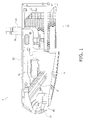
- FIG. 1 is a side view schematic configuration drawing of an indoor unit 3 of an air conditioning apparatus pertaining to an embodiment of the present invention.
- FIG. 2 is an arrangement schematic configuration drawing of the inside of the indoor unit 3 as seen in a side view.
- FIG. 3 is an arrangement schematic configuration drawing of the inside of the indoor unit 3 as seen in a top view.
- FIG. 4 is a partially enlarged schematic configuration drawing of an airflow downstream side of the inside of the indoor unit 3.
- FIG. 5 is a front view of a state where a horizontal flap 31 is most blocking an air outlet 22.
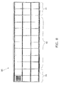
- FIG. 6 is a rear view of a casing 20.
- the indoor unit 3 of an air conditioning apparatus is a ceiling-suspended type of indoor unit that is connected via refrigerant connection pipes to an unillustrated outdoor unit and is placed in the neighborhood of a side wall in an upper space inside a room; the indoor unit 3 of an air conditioning apparatus is equipped with a casing 20, a fan 25, a heat exchanger 5, a drain pan 6, a seal material 7, a seal material 8, a horizontal flap 31, perpendicular flaps 32, support members 33, perpendicular drive bars 39, a filter 90, and a control board 70, etc.
- the right side represents the rear side
- the left side represents the front side
- the upper side represents the upper side
- the lower side represents the lower side.
- the casing 20 has an air inlet 21, which opens in the vertical direction in the neighborhood of the rear side of the lower surface, and an air outlet 22 (see FIG. 5 , etc.), which is disposed in a position somewhat on the lower side from the neighborhood of the substantial center of the front side in the vertical direction and extends in the left-and-right direction as seen in a front view.
- an air inlet 21 which opens in the vertical direction in the neighborhood of the rear side of the lower surface
- an air outlet 22 see FIG. 5 , etc.
- a cover 29C that is made of resin and is disposed in the neighborhood of the left side end portion illustrated.
- an opening that opens in the plate thickness direction including also the lower end portion.
- the fan 25 can form an airflow leading from the air inlet 21 to the air outlet 22 inside the casing 20; as shown in FIG. 3 and FIG. 7 , the fan 25 has a first sirocco fan 25a, a second sirocco fan 25b, a third sirocco fan 25c, and a fourth sirocco fan 25d, which have a common axis, and a fan motor 25M that supplies to these sirocco fans motive power for driving them to rotate.
- the fan motor 25M is placed between the first sirocco fan 25a and second sirocco fan 25b and the third sirocco fan 25c and fourth sirocco fan 25d.
- a fan shaft 25B is used to couple together the sirocco fans via couplings and is supported, in such a way that it may freely rotate, by bearings on both ends. In this way, by equally placing two sirocco fans each on the left side and the right side, noise can be reduced.
- the heat exchanger 5 has plural heat radiating fins 51, which are placed in such a way that their plate thickness direction coincides with the front view left-and-right direction, and plural heat transfer pipes 52, which are placed in such a way that their lengthwise direction coincides with the front view left-and-right direction and penetrate the plural heat radiating fins 51.
- one step of a refrigeration cycle is performed by causing refrigerant flowing into the heat exchanger 5 from the outdoor unit via the liquid pipe 28 or the gas pipe 29 serving as refrigerant connection pipes to pass through the heat exchanger 5 and thereafter sending the refrigerant back to the outdoor unit via the gas pipe 29 or the liquid pipe 28.
- the heat radiating fins 51 are placed side-by-side at 1.5 mm intervals in their plate thickness direction.
- the plate thickness of the heat radiating fins 51 is 0.1 mm.
- the drain pan 6 is placed in such a way as to cover the underside of the heat exchanger 5 while ensuring a gap in the vertical direction between the drain pan 6 and the lower end portion of the heat exchanger 5; the drain pan 6 has an upper downstream portion 6a, which configures the upper surface of the drain pan 6 and is placed on the downstream side in the airflow direction, and a lower upstream portion 6b, which is placed on the airflow direction upstream side of the upper downstream portion 6a and configures the upper surface of the drain pan 6 on the lower side of the upper downstream portion 6a.
- the seal material 7 is placed in the gap between the lower end portion of the heat exchanger 5 and the upper downstream portion 6a of the drain pan 6 and is configured by polyethylene foam called opcell or the like.
- the seal material 8 is placed in a gap between the upper end portion of the heat exchanger 5 and the undersurface portion of the upper surface of the casing 20 and is configured by polyethylene foam called opcell or the like.
- the horizontal flap 31 is placed in such a way as to cover the space above the air outlet 22 in the casing 20, is configured in such a way that its lengthwise direction coincides with the left-and-right direction when seen from the front, and its axis of rotation extends in the left-and-right direction (horizontal direction) as seen in a front view.
- the horizontal flap 31 can adjust, in the up-and-dawn direction, the direction of the airflow blown out from the air outlet 22 as a result of its postural angle being changed taking a rotating shaft 31 m as its center of rotation.
- the horizontal flap 31 is configured in such a way that, even in a state where it has substantially closed the air outlet 22, a gap having a width in the airflow direction of 10 mm or more (here, about 3 cm) remains between the horizontal flap 31 and the air outlet 22. Because of this, even if the horizontal flap 31 has become the posture where it most blocks the air outlet 22 at the time of shutdown after a cooling operation, circulation of air between the inside of the casing 20 of the indoor unit 3 and the outside of the casing 20 can be ensured to suppress the propagation of various bacteria.
- the perpendicular flaps 32 are placed on the airflow direction upstream side of the horizontal flap 31, that is, on the lower end side of the air outlet 22 on the interior side of the casing 20, and rotating shafts 35 extend in the up-and-down direction (vertical direction) as seen in a front view.
- the perpendicular flaps 32 can adjust, in the left-and-right direction, the direction of the airflow blown out from the air outlet 22 as a result of their postural angles being changed taking the rotating shafts 35 as centers of rotation.
- the perpendicular flaps 32 include small perpendicular flaps 32a, large perpendicular flaps 32b, and end portion perpendicular flaps 32c. Of these, the small perpendicular flaps 32a are placed near the support members 33 and are the smallest among the perpendicular flaps 32.
- the support members 33 extend from the upper end of the air outlet 22 in the casing 20 to the neighborhood of the lower end of the air outlet 22 and thereafter extend toward the airflow direction downstream side while heading slightly upward; the support members 33 share with the horizontal flap 31 the rotating shaft 31m at their airflow direction downstream side distal ends, whereby the support members 33 rotatably support the horizontal flap 31.
- the horizontal flap 31 is long in the front view left-and-right direction, so by supporting the horizontal flap 31 midway, bending of the horizontal flap 31 can be suppressed.
- the plate thickness direction of the support members 33 coincides with the horizontal direction, which is the lengthwise direction of the air outlet 22; in a posture where the perpendicular flaps 32 are not inclined, the plate thickness direction of the perpendicular flaps 32 and the plate thickness direction of the support members 33 become the same, and air passage resistance with respect to the airflow can be kept small.
- the perpendicular drive bars 39 are members that lump together four each of the perpendicular flaps 32 and change the postural angles of those perpendicular flaps 32; the perpendicular drive bars 39 obtain driving force from an unillustrated airflow direction adjusting mechanism and change the postural angles of the perpendicular flaps 32.
- the filter 90 is mounted in the air inlet 21 in the casing 20; as shown in FIG. 8 , which is a plan view, and FIG. 9 , which is a side view, the filter 90 has low-thickness portions 91 that are disposed on both the left and right end portions of the filter 90 and a high-thickness portion 92 that is disposed between the low-thickness portions 91.
- the filter 90 can be fitted exactly in the installation position of the filter 90.
- the pitches configuring the openings in the filter 90 are equally spaced.
- the control board 70 performs control of the aforementioned refrigeration cycle and performs automatic adjustment control of the postural angle of the horizontal flap 31 and the postural angles of the perpendicular flaps 32, etc.
- FIG. 10 shows a front side perspective view of the neighborhood of the air outlet 22.
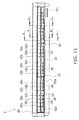
- FIG. 11 shows a front view of the neighborhood of the air outlet 22.
- FIG. 12 shows partial sectional explanatory drawings of the neighborhood of the air outlet 22.
- FIG. 13 shows a top view in a state where the perpendicular flaps 32 are not inclined.
- FIG. 14 shows a top view in a state where the perpendicular flaps 32 are inclined.
- the support members 33 that support the horizontal flap 31 are disposed in two places in such a way as to divide the width of the air outlet 22 in the left-and-right direction substantially equally into thirds.
- the end portion perpendicular flaps 32c are disposed on both the left and right end portions of the air outlet 22.
- the distances between the end portion perpendicular flaps 32c and the left and right wall surfaces of the air outlet 22 are short, so the end portion perpendicular flaps 32c are designed to be small in such a way that it becomes difficult for dew condensation to form on them.
- the small perpendicular flaps 32a are placed one each in the left and right areas, excluding the middle area, of the areas in the air outlet 22 that is divided equally into thirds by the support members 33.
- the small perpendicular flap 32a placed in the area on the left side is placed farthest to the right among the perpendicular flaps 32 in the area on the left side.
- the small perpendicular flap 32a placed in the area on the right side is placed farthest to the left among the perpendicular flaps 32 in the area on the right side. In this way, left-and-right symmetry of the perpendicular flaps 32 is ensured.
- the distance of closest approach between the support member 33 on the front view left side and the rotating shaft 35 of the nearest small perpendicular flap 32a is shorter than any distance of the distances of closest approach between this support member 33 on the front view left side and the rotating shafts 35 of the other perpendicular flaps 32.
- the distance of closest approach between the surface of the support member 33 on the front view left side and the surface of the nearest small perpendicular flap 32a is shorter than any distance of the distances of closest approach between the surface of the support member 33 on the front view left side and the surfaces of the other perpendicular flaps 32.
- the large perpendicular flaps 32b are placed other than in the portions described above; as single groups in which four each of the perpendicular flaps 32 move in the same way, two groups are disposed in the area on the left side, two groups are disposed in the middle, and two groups are disposed in the area on the right side.
- the perpendicular flaps 32 in each of these groups are lumped together by the corresponding one perpendicular drive bar 39, and the postural angles of the perpendicular flaps 32 in these groups can be changed by group.
- the small perpendicular flaps 32a, the large perpendicular flaps 32b, the end portion perpendicular flaps 32c, and the support members 33 are placed in such a way that none have portions that overlap in the airflow direction as seen in a front view.
- FIG 12(a) shows a side view configuration drawing of a state where the front view left side is seen from section a-a in FIG 11 .
- FIG 12(b) shows a side view sectional drawing of a state where the front view left side is seen from section b-b in FIG. 11 .
- FIG. 12(c) shows a side view sectional drawing of a state where the front view left side is seen from section c-c in FIG. 11 .
- the support members 33 and the small perpendicular flaps 32a are placed in such a way that they have portions that overlap each other. Because of this, miniaturization in the airflow direction can be achieved compared to a case where the support members 33 and the small perpendicular flaps 32a are placed in such a way that they do not overlap as seen in a side view.
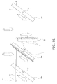
- FIG 15 shows a partially enlarged top view of the portion indicated by arrow view P in FIGS. 13 and 14 .
- the smaller angle of the angles formed by the lengthwise direction of the support member 33 as seen in a top view and the lengthwise direction of the nearest perpendicular flap 32 is about 70 degrees.
- FIG 16 shows a top view showing a comparative example corresponding to FIG. 15 .
- FIG. 16 a case where the perpendicular flap 32 nearest to the support member 33 is a large perpendicular flap 32b is shown as a comparative example.
- airflows F formed by the fan 25 pass along the right side of the support member 33 and the left side of the nearest large perpendicular flap 32b and are blown out into the room.
- the gap on the upwind side between the support member 33 and the nearest large perpendicular flap 32b is small, so it is difficult for the airflows F to flow in between the support member 33 and the nearest large perpendicular flap 32b.
- FIG 15 which shows a top view of the support member 33 and the nearest small perpendicular flap 32a in the indoor unit 3 of an air conditioning apparatus of the above-described embodiment
- the small perpendicular flap 32a and not the large perpendicular flap 32b is employed as the perpendicular flap 32 nearest to the support member 33, so an airflow Fs of the airflows F passes along the vertical direction upper side of the small perpendicular flap 32a. For this reason, cool air at the time of the cooling operation can be supplied also between the support member 33 and the nearest small perpendicular flap 32a.
- the entire surfaces of the support member 33 and the nearest small perpendicular flap 32a can be cooled by the cool airflows F and Fs, the formation of dew condensation can be supported because it is difficult for irregularities to arise in the surface temperatures, and the formation of dew condensation can be suppressed also from the standpoint that inflow of air from the room can be suppressed.
- the present invention can also be applied to a case where other flaps are placed near support members that support flaps, so for example, the present invention may also be applied with respect to an indoor unit of a floor-standing type air conditioning apparatus where the lengthwise direction of the air outlet is the vertical direction.
- a perpendicular flap is supported by the support member, and the horizontal flap nearest to the support member is miniaturized.
- the present invention is not limited to this; for example, as shown in FIG. 17 , the present invention may also be configured as an indoor unit 203 of an air conditioning apparatus that employs a support member 233 where the nearest perpendicular flap 32 is a small perpendicular flap 32a. In this case, the formation of dew condensation can be suppressed in the neighborhoods of both the support member 33 and the support member 233.
- the perpendicular flaps 32 of the present invention are not limited to this; for example, focusing on surface area, the perpendicular flaps 32 may also be perpendicular flaps 32 where the surface area of the small perpendicular flaps 32a is designed to be smaller than the surface area of the large perpendicular flaps 32b.
- the perpendicular flaps 32 may also be perpendicular flaps 32 where the volume of the small perpendicular flaps 32a. is designed to be smaller than the volume of the large perpendicular flaps 32b.
- the perpendicular flaps 32 may also be perpendicular flaps 32 where the length of the small perpendicular flaps 32a in the airflow direction is designed to be shorter than the length of the large perpendicular flaps 32b in the airflow direction. Moreover, the perpendicular flaps 32 may also be perpendicular flaps 32 whose lengths in the vertical direction are about the same and where the length of the small perpendicular flaps 32a in the airflow direction is designed to be shorter than the length of the large perpendicular flaps 32b in the airflow direction.
- the perpendicular flaps 32 may also be perpendicular flaps 32 where the length of the small perpendicular flaps 32a in the airflow direction is designed to be shorter than the length of the large perpendicular flaps 32b in the airflow direction.
- the perpendicular flaps 32 may also be perpendicular flaps 32 where the length of the small perpendicular flaps 32a in the vertical direction is designed to be shorter than the length of the large perpendicular flaps 32b in the vertical direction. Moreover, the perpendicular flaps 32 may also be perpendicular flaps 32 whose lengths in the airflow direction are about the same and where the length of the small perpendicular flaps 32a in the vertical direction is designed to be shorter than the length of the large perpendicular flaps 32b in the vertical direction.
- the occurrence of drain water can be suppressed even in a case where other flaps having the following configuration are placed instead of the small perpendicular flaps 32a described above.
- These other flaps are flaps which, in a case where they are placed instead of the small perpendicular flaps 32a in the positions where the small perpendicular flaps 32a described above had been placed, can reduce the quantity of drain water that can arise more than the quantity of drain water that can arise between the large perpendicular flaps 32b and the support members 33 in a case where the large perpendicular flaps 32b described above are placed instead in the same positions.
- the perpendicular flaps 32 may also be configured from at least two types of flaps including other flaps.
- the types of flaps here are divided by, for example, shape, size, whether or not they have been surface-treated, etc.
- the indoor unit of an air conditioning apparatus of the present invention can suppress dew condensation that can arise between a perpendicular flap and a support member in a case where, for example, a horizontal flap is supported in such a way that it may freely rotate by a support member, so the indoor unit of an air conditioning apparatus of the present invention is particularly useful in a case where it is applied to an indoor unit of an air conditioning apparatus where a horizontal flap is supported by a support member.
- Patent Citation 1 JP-A No. 2006-132789
Landscapes
- Engineering & Computer Science (AREA)
- Chemical & Material Sciences (AREA)
- Combustion & Propulsion (AREA)
- Mechanical Engineering (AREA)
- General Engineering & Computer Science (AREA)
- Air-Flow Control Members (AREA)
- Devices For Blowing Cold Air, Devices For Blowing Warm Air, And Means For Preventing Water Condensation In Air Conditioning Units (AREA)
- Air Filters, Heat-Exchange Apparatuses, And Housings Of Air-Conditioning Units (AREA)
- Duct Arrangements (AREA)
Abstract
Description
- The present invention relates to an indoor unit of an air conditioning apparatus.
- For example, as described in patent citation 1 (
JP-A No. 2006-132789 - In an air conditioning apparatus where a horizontal flap is disposed such as described above, sometimes a support member that rotatably supports the horizontal flap is disposed in the neighborhood of the middle of the horizontal flap in the lengthwise direction of the horizontal flap or the like in order to keep the horizontal flap from ending up bending due to its self weight or the like.
- In this way, in a case where a support member for the horizontal flap is disposed, there are cases where the distances between the plural perpendicular flaps and the support member are non-uniform. In such cases, sometimes it becomes difficult to evenly expose to cool air the entire surface of the support member and the entire surface of the perpendicular flap that is placed close to the support member. In this case, there is the fear that dew condensation will form at portions not sufficiently exposed to the cool air.
- It is a problem of the present invention to provide an indoor unit of an air conditioning apparatus that can suppress the formation of dew condensation between a support member that rotatably supports a first airflow direction adjusting plate and a second airflow direction adjusting plate that performs airflow direction adjustment in a direction differing from that of the first airflow direction adjusting plate.
- An indoor unit of an air conditioning apparatus of a first aspect is an indoor unit of an air conditioning apparatus and is equipped with a casing, a heat exchanger, a fan, a first airflow direction adjusting plate, plural second airflow direction adjusting plates, and a support member. The casing has an air inlet and an air outlet. The heat exchanger is placed inside the casing. The fan generates an airflow leading from the air inlet to the air outlet. The first airflow direction adjusting plate can, by rotating taking a first direction as its axial direction, adjust the direction of the airflow blown out from the air outlet. The plural second airflow direction adjusting plates can, by rotating taking a second direction that is substantially perpendicular with respect to the first direction as their axial direction, adjust the direction of the airflow blown out from the air outlet. The support member rotatably supports the first airflow direction adjusting plate with respect to the casing at least in a portion of the air outlet other than both end portions in the first direction, and at least one of the support member is disposed. The plural second airflow direction adjusting plates include at least one each of a third airflow direction adjusting plate and a fourth airflow direction adjusting plate that is placed in a location where its distance to the support member is the shortest and which is smaller than the third airflow direction adjusting plate. Here, a case where the fourth airflow direction adjusting plate is smaller than the third airflow direction adjusting plate may, for example, be any of a case where the surface area of the fourth airflow direction adjusting plate is smaller than the surface area of the third airflow direction adjusting plate, a case where the volume of the fourth airflow direction adjusting plate is smaller than the volume of the third airflow direction adjusting plate, a case where the length of the fourth airflow direction adjusting plate in the airflow direction is shorter than the length of the third airflow direction adjusting plate in the airflow direction regardless of their lengths in the second direction, and a case where the length of the fourth airflow direction adjusting plate in the second direction is shorter than the length of the third airflow direction adjusting plate in the second direction regardless of their lengths in the airflow direction. The support member may also rotatably support the first airflow direction adjusting plate at both end portions of the air outlet in the first direction.
- Usually, when at attempt is made to cause cool air that has been conditioned to pass through the air outlet, in a case where the distance between the fourth airflow direction adjusting plate and the support member is small, there are cases where it becomes difficult for this cool air to flow in such a way as to go along the entire surface of the fourth airflow direction adjusting plate and the entire surface of the support member.
- With respect to this, in this indoor unit of an air conditioning apparatus, first, because the support member is disposed, bending at the portion between both end portions of the air outlet in the first direction can be suppressed. Additionally, even in a case where this support member is disposed, the second airflow direction adjusting plate that is placed in the position closest to the support member is not the third airflow direction adjusting plate but the fourth airflow direction adjusting plate that is smaller than the third airflow direction adjusting plate. For this reason, it becomes easier to allow the cool air to touch the entire surfaces of both the support member and the second airflow direction adjusting plate that is positioned in the neighborhood of the support member. Because of this, temperature irregularities in the entire surfaces of both the support member and the second airflow direction adjusting plate that is positioned in the neighborhood of the support member can be reduced, and the formation of dew condensation can be suppressed. Moreover, not only can the airflow direction be effectively adjusted by the third airflow direction adjusting plate, but at the portion where the fourth airflow direction adjusting plate is disposed, airflow direction adjustment also becomes possible to a certain extent while suppressing the formation of dew condensation.
- An indoor unit of an air conditioning apparatus of a second aspect is the indoor unit of an air conditioning apparatus of the first aspect, wherein the support member and the plural second airflow direction adjusting plates are placed in positions where they do not overlap each other in a case where they are seen from the direction of the airflow passing through the air outlet in the casing.
- In this indoor unit of an air conditioning apparatus, the support member and the plural second airflow direction adjusting plates are placed in positions where they do not overlap each other as seen in the direction of the airflow passing through the air outlet, so there are cases where the support member and the second airflow direction adjusting plate nearest to the support member cooperatively form air passage resistance. In such cases, it is easy for irregularities to arise in the surface temperatures of the support member and the nearest second airflow direction adjusting plate, and there is the fear that dew condensation will form. In this indoor unit of an air conditioning apparatus, even in a case where an arrangement structure of the support member and the second airflow direction adjusting plates where there is the fear that dew condensation will form in this way is employed, the formation of dew condensation can be suppressed by using the fourth airflow direction adjusting plate for the second airflow direction adjusting plate nearest to the support member.
- An indoor unit of an air conditioning apparatus of a third aspect is the indoor unit of an air conditioning apparatus of the first aspect or the second aspect, wherein a distance of closest approach between the shaft of the fourth airflow direction adjusting plate and the support member is the shortest among distances of closest approach between shafts of the plural second airflow direction adjusting plates and the support member.
- For example, it is easy for air passage resistance to arise in the space between the support member and the second airflow direction adjusting plate whose shaft is placed in a location that is closest to the support member.
- With respect to this, in this indoor unit of an air conditioning apparatus, the formation of dew condensation can be prevented by employing the fourth airflow direction adjusting plate as the second airflow direction adjusting plate whose shaft is placed in a location that is closest to the support member.
- An indoor unit of an air conditioning apparatus of a fourth aspect is the indoor unit of an air conditioning apparatus of the first aspect or the second aspect, wherein a distance of closest approach between a rotational driving locus of the fourth airflow direction adjusting plate and the support member is the shortest among distances of closest approach between rotational driving loci of the plural second airflow direction adjusting plates and the support member.
- For example, it is easy for air passage resistance to arise in the space between the support member and the second airflow direction adjusting plate most approaching the support member in its driving locus.
- With respect to this, in this indoor unit of an air conditioning apparatus, the formation of dew condensation can be prevented by using the fourth airflow direction adjusting plate for the second airflow direction adjusting plate most approaching the support member in its driving locus.
- An indoor unit of an air conditioning apparatus of a fifth aspect is the indoor unit of an air conditioning apparatus of any of the first aspect to the fourth aspect, wherein the plural second airflow direction adjusting plates are placed side-by-side in the first direction. As seen in the first direction, at least parts of the second airflow direction adjusting plates and the support member overlap.
- In this indoor unit of an air conditioning apparatus, the second airflow direction adjusting plates and the support member are placed in such a way that they have portions that overlap in the first direction, so the apparatus can be miniaturized in regard to direction components that are perpendicular with respect to the first direction.
- An indoor unit of an air conditioning apparatus of a sixth aspect is the indoor unit of an air conditioning apparatus of the fifth aspect, wherein the support member has a plate-like portion that extends in the direction of the airflow passing through the air outlet. The plate thickness direction of the plate-like portion is the first direction.
- In this indoor unit of an air conditioning apparatus, the support member has a width in the direction of the airflow that passes through the air outlet, so the support member can more stably support the first airflow direction adjusting plate. Additionally, even in a case where the support member employs a shape that stably supports the first airflow direction adjusting plate in this way, its plate thickness direction in the neighborhood of the air outlet coincides with the first direction, so air passage resistance resulting from the support member itself can be kept small.
- An indoor unit of an air conditioning apparatus of a seventh aspect is the indoor unit of an air conditioning apparatus of the sixth aspect, wherein in a state where the distance of closest approach between the support member and the fourth airflow direction adjusting plate becomes the smallest as a result of the fourth airflow direction adjusting plate rotating, an angle on a downwind side in the airflow direction of angles formed by the support member and the fourth airflow direction adjusting plate as seen from the second direction is from 10 degrees to 90 degrees.
- In a state where the distance of closest approach between the support member and the fourth airflow direction adjusting plate becomes the smallest and the angle on the downwind side becomes 10 degrees or more and 90 degrees or less, cool air that has been conditioned mainly passes in such a way as to go along the surface of the support member on the upwind side and the surface of the fourth airflow direction adjusting plate on the upwind side. In this case, it is difficult for the cool air that has been conditioned to touch the surface of the support member on the downwind side and the surface of the fourth airflow direction adjusting plate on the downwind side, and it is easy for humid warm air convectively flowing from the room to flow in. In this case, it becomes easy for a situation to develop where the temperature differs between the upwind-side surface and the downwind-side surface of the support member and for a situation to develop where the temperature differs between the upwind-side surface and the downwind-side surface of the fourth airflow direction adjusting plate.
- With respect to this, in this indoor unit of an air conditioning apparatus, the fourth airflow direction adjusting plate is employed as the second airflow direction adjusting plate nearest to the support member, so it becomes easier to allow cool air that has been conditioned to touch both the upwind-side surface and the downwind-side surface of the support member or both the upwind side and the downwind side of the fourth airflow direction adjusting plate. Because of this, it becomes easier to keep temperature differences between the upwind-side surfaces and the downwind-side surfaces small in the support member and the second airflow direction adjusting plates, and the formation of dew condensation can be suppressed.
- An indoor unit of an air conditioning apparatus of an eighth aspect is the indoor unit of an air conditioning apparatus of any of the first aspect to the seventh aspect, wherein the first airflow direction adjusting plate can, by rotating taking the first direction as its axis-of-rotation direction, adjust in an up-and-down direction the direction of the airflow blown out from the air outlet. The plural second airflow direction adjusting plates can, by rotating taking the second direction as their axis-of-rotation direction, adjust in a left-and-right direction the direction of the airflow blown out from the air outlet.
- In this indoor unit of an air conditioning apparatus, the direction of the airflow that is blown out can be adjusted in the up-and-down direction by the first airflow direction adjusting plate and in the left-and-right direction by the plural second airflow direction adjusting plates, so the direction in which the airflow is blown out can be adjusted in the up-and-down and left-and-right directions.
- An indoor unit of an air conditioning apparatus of a ninth aspect is the indoor unit of an air conditioning apparatus of any of the first aspect to the eighth aspect, wherein the casing has only one of the air outlet. The lengthwise direction of the air outlet is a substantially horizontal direction.
- Usually, in a case where there is only one air outlet, the length of the air outlet in the horizontal direction tends to become long in order to ensure a range in which the conditioned air can be supplied. In this way, even in a case where the length of the air outlet in the horizontal direction becomes long, in this indoor unit of an air conditioning apparatus, the support member that supports the first airflow direction adjusting plate is disposed. Because of this, bending of the first airflow direction adjusting plate can be suppressed.
- An indoor unit of an air conditioning apparatus of a tenth aspect is the indoor unit of an air conditioning apparatus of any of the first aspect to the ninth aspect, wherein the fourth airflow direction adjusting plate is the smallest of the plural second airflow direction adjusting plates.
- In this indoor unit of an air conditioning apparatus, the formation of dew condensation on the surfaces of the fourth airflow direction adjusting plate and the support member can be more effectively suppressed.
- An indoor unit of an air conditioning apparatus of an eleventh aspect is the indoor unit of an air conditioning apparatus of any of the first aspect to the tenth aspect, wherein the indoor unit is a ceiling-suspended type.
- In this indoor unit of an air conditioning apparatus, the formation of dew condensation can be suppressed even with a ceiling-suspended type.
- In the indoor unit of an air conditioning apparatus of the first aspect, not only can the airflow direction be effectively adjusted by the third airflow direction adjusting plate, but at the portion where the fourth airflow direction adjusting plate is disposed, airflow direction adjustment also becomes possible to a certain extent while suppressing the formation of dew condensation.
- In the indoor unit of an air conditioning apparatus of the second aspect, even in a case where an arrangement structure of the support member and the second airflow direction adjusting plates where there is the fear that dew condensation will form is employed, the formation of dew condensation can be suppressed.
- In the indoor unit of an air conditioning apparatus of the third aspect, the formation of dew condensation can be prevented by employing the fourth airflow direction adjusting plate as the second airflow direction adjusting plate whose shaft is placed in a location that is closest to the support member.
- In the indoor unit of an air conditioning apparatus of the fourth aspect, the formation of dew condensation can be prevented by using the fourth airflow direction adjusting plate for the second airflow direction adjusting plate most approaching the support member in its driving locus.
- In the indoor unit of an air conditioning apparatus of the fifth aspect, the apparatus can be miniaturized in regard to direction components that are perpendicular with respect to the first direction.
- In the indoor unit of an air conditioning apparatus of the sixth aspect, air passage resistance resulting from the support member itself can be kept small.
- In the indoor unit of an air conditioning apparatus of the seventh aspect, it becomes easier to keep temperature differences between the upwind-side surfaces and the downwind-side surfaces small in the support member and the second airflow direction adjusting plates, and the formation of dew condensation can be suppressed.
- In the indoor unit of an air conditioning apparatus of the eighth aspect, the direction in which the airflow is blown out can be adjusted in the up-and-down and left-and-right directions.
- In the indoor unit of an air conditioning apparatus of the ninth aspect, bending of the first airflow direction adjusting plate can be suppressed.
- In the indoor unit of an air conditioning apparatus of the tenth aspect, the formation of dew condensation on the surfaces of the fourth airflow direction adjusting plate and the support member can be more effectively suppressed.
- In the indoor unit of an air conditioning apparatus of the eleventh aspect, the formation of dew condensation can be suppressed even with a ceiling-suspended type.
-
-
FIG. 1 is a side view schematic explanatory drawing of an indoor unit of an air conditioning apparatus pertaining to an embodiment of the present invention. -
FIG. 2 is a side view schematic arrangement configuration drawing of the indoor unit. -
FIG. 3 is a top view schematic arrangement configuration drawing of the indoor unit. -
FIG. 4 is a partially enlarged schematic configuration drawing of an air outlet side. -
FIG. 5 is a front view of the indoor unit. -
FIG. 6 is a rear view of the indoor unit. -
FIG. 7 is a drawing showing the detailed configuration of a fan. -
FIG. 8 is a plan view of a filter. -
FIG. 9 is a sectional view of the filter. -
FIG. 10 is a front side perspective view showing the neighborhood of the air outlet. -
FIG. 11 is a front view showing the neighborhood of the air outlet. -
FIG. 12(a) is a side view showing a case where the front view left side is seen from section a-a inFIG. 11 . -
FIG. 12(b) is a side view showing a case where the front view left side is seen from section b-b inFIG. 11 . -
FIG. 12(c) is a side view showing a case where the front view left side is seen from section c-c inFIG. 11 . -
FIG. 13 is a top view showing the lower portion of the interior of the indoor unit in a case where perpendicular flaps are not inclined. -
FIG. 14 is a top view showing the lower portion of the interior of the indoor unit in a case where the perpendicular flaps are inclined. -
FIG. 15 is a top view showing the formation of dew condensation being suppressed by small perpendicular flaps. -
FIG. 16 is a top view showing a comparative example where dew condensation forms because of large perpendicular flaps. -
FIG. 17 is a top view of the lower portion of an indoor unit in modification (B). -
FIG. 1 is a side view schematic configuration drawing of anindoor unit 3 of an air conditioning apparatus pertaining to an embodiment of the present invention.FIG. 2 is an arrangement schematic configuration drawing of the inside of theindoor unit 3 as seen in a side view.FIG. 3 is an arrangement schematic configuration drawing of the inside of theindoor unit 3 as seen in a top view.FIG. 4 is a partially enlarged schematic configuration drawing of an airflow downstream side of the inside of theindoor unit 3.FIG. 5 is a front view of a state where ahorizontal flap 31 is most blocking anair outlet 22.FIG. 6 is a rear view of acasing 20. - The
indoor unit 3 of an air conditioning apparatus is a ceiling-suspended type of indoor unit that is connected via refrigerant connection pipes to an unillustrated outdoor unit and is placed in the neighborhood of a side wall in an upper space inside a room; theindoor unit 3 of an air conditioning apparatus is equipped with acasing 20, afan 25, aheat exchanger 5, adrain pan 6, aseal material 7, aseal material 8, ahorizontal flap 31,perpendicular flaps 32,support members 33, perpendicular drive bars 39, afilter 90, and acontrol board 70, etc. - In
FIG. 1 andFIG. 2 , in the illustrations, the right side represents the rear side, the left side represents the front side, the upper side represents the upper side, and the lower side represents the lower side. - The
casing 20 has anair inlet 21, which opens in the vertical direction in the neighborhood of the rear side of the lower surface, and an air outlet 22 (seeFIG. 5 , etc.), which is disposed in a position somewhat on the lower side from the neighborhood of the substantial center of the front side in the vertical direction and extends in the left-and-right direction as seen in a front view. With respect to theair inlet 21, only one is disposed. Further, with respect to theair outlet 22 also, only one is disposed. Only oneair outlet 22 is disposed in the front side, and the front view left-and-right direction coincides with the lengthwise direction of theair outlet 22. On the rear surface of thecasing 20, as shown inFIG. 6 , there is disposed acover 29C that is made of resin and is disposed in the neighborhood of the left side end portion illustrated. In the portion blocked by thecover 29C, there is disposed an opening that opens in the plate thickness direction including also the lower end portion. Because of this, in the case of using existing pipes without using aliquid pipe 28 and agas pipe 29 such as described below, the existing pipes can be passed through the underside of thecasing 20 at the time of installation of theindoor unit 3. An unillustrated sheet metal member is fastened by screws to this rear side, whereby the rear side can be made structurally strong even though an opening is disposed in it. - The
fan 25 can form an airflow leading from theair inlet 21 to theair outlet 22 inside thecasing 20; as shown inFIG. 3 andFIG. 7 , thefan 25 has afirst sirocco fan 25a, asecond sirocco fan 25b, athird sirocco fan 25c, and afourth sirocco fan 25d, which have a common axis, and afan motor 25M that supplies to these sirocco fans motive power for driving them to rotate. Thefan motor 25M is placed between thefirst sirocco fan 25a andsecond sirocco fan 25b and thethird sirocco fan 25c andfourth sirocco fan 25d. In thefan 25, afan shaft 25B is used to couple together the sirocco fans via couplings and is supported, in such a way that it may freely rotate, by bearings on both ends. In this way, by equally placing two sirocco fans each on the left side and the right side, noise can be reduced. - The
heat exchanger 5 has pluralheat radiating fins 51, which are placed in such a way that their plate thickness direction coincides with the front view left-and-right direction, and pluralheat transfer pipes 52, which are placed in such a way that their lengthwise direction coincides with the front view left-and-right direction and penetrate the pluralheat radiating fins 51. In theheat exchanger 5, one step of a refrigeration cycle is performed by causing refrigerant flowing into theheat exchanger 5 from the outdoor unit via theliquid pipe 28 or thegas pipe 29 serving as refrigerant connection pipes to pass through theheat exchanger 5 and thereafter sending the refrigerant back to the outdoor unit via thegas pipe 29 or theliquid pipe 28. Theheat radiating fins 51 are placed side-by-side at 1.5 mm intervals in their plate thickness direction. The plate thickness of theheat radiating fins 51 is 0.1 mm. - The
drain pan 6 is placed in such a way as to cover the underside of theheat exchanger 5 while ensuring a gap in the vertical direction between thedrain pan 6 and the lower end portion of theheat exchanger 5; thedrain pan 6 has an upperdownstream portion 6a, which configures the upper surface of thedrain pan 6 and is placed on the downstream side in the airflow direction, and a lowerupstream portion 6b, which is placed on the airflow direction upstream side of the upperdownstream portion 6a and configures the upper surface of thedrain pan 6 on the lower side of the upperdownstream portion 6a. On the upper surface of thedrain pan 6, there is disposed a concavo-convex shapedportion 61 that is disposed on the border between the upperdownstream portion 6a and the lowerupstream portion 6b. - The
seal material 7 is placed in the gap between the lower end portion of theheat exchanger 5 and the upperdownstream portion 6a of thedrain pan 6 and is configured by polyethylene foam called opcell or the like. - The
seal material 8 is placed in a gap between the upper end portion of theheat exchanger 5 and the undersurface portion of the upper surface of thecasing 20 and is configured by polyethylene foam called opcell or the like. - The
horizontal flap 31 is placed in such a way as to cover the space above theair outlet 22 in thecasing 20, is configured in such a way that its lengthwise direction coincides with the left-and-right direction when seen from the front, and its axis of rotation extends in the left-and-right direction (horizontal direction) as seen in a front view. Thehorizontal flap 31 can adjust, in the up-and-dawn direction, the direction of the airflow blown out from theair outlet 22 as a result of its postural angle being changed taking arotating shaft 31 m as its center of rotation. Thehorizontal flap 31 is configured in such a way that, even in a state where it has substantially closed theair outlet 22, a gap having a width in the airflow direction of 10 mm or more (here, about 3 cm) remains between thehorizontal flap 31 and theair outlet 22. Because of this, even if thehorizontal flap 31 has become the posture where it most blocks theair outlet 22 at the time of shutdown after a cooling operation, circulation of air between the inside of thecasing 20 of theindoor unit 3 and the outside of thecasing 20 can be ensured to suppress the propagation of various bacteria. - The perpendicular flaps 32 are placed on the airflow direction upstream side of the
horizontal flap 31, that is, on the lower end side of theair outlet 22 on the interior side of thecasing 20, androtating shafts 35 extend in the up-and-down direction (vertical direction) as seen in a front view. The perpendicular flaps 32 can adjust, in the left-and-right direction, the direction of the airflow blown out from theair outlet 22 as a result of their postural angles being changed taking therotating shafts 35 as centers of rotation. The perpendicular flaps 32 include smallperpendicular flaps 32a, largeperpendicular flaps 32b, and end portion perpendicular flaps 32c. Of these, the smallperpendicular flaps 32a are placed near thesupport members 33 and are the smallest among the perpendicular flaps 32. - The
support members 33 extend from the upper end of theair outlet 22 in thecasing 20 to the neighborhood of the lower end of theair outlet 22 and thereafter extend toward the airflow direction downstream side while heading slightly upward; thesupport members 33 share with thehorizontal flap 31 therotating shaft 31m at their airflow direction downstream side distal ends, whereby thesupport members 33 rotatably support thehorizontal flap 31. Thehorizontal flap 31 is long in the front view left-and-right direction, so by supporting thehorizontal flap 31 midway, bending of thehorizontal flap 31 can be suppressed. The plate thickness direction of thesupport members 33 coincides with the horizontal direction, which is the lengthwise direction of theair outlet 22; in a posture where theperpendicular flaps 32 are not inclined, the plate thickness direction of theperpendicular flaps 32 and the plate thickness direction of thesupport members 33 become the same, and air passage resistance with respect to the airflow can be kept small. - The perpendicular drive bars 39 are members that lump together four each of the
perpendicular flaps 32 and change the postural angles of thoseperpendicular flaps 32; the perpendicular drive bars 39 obtain driving force from an unillustrated airflow direction adjusting mechanism and change the postural angles of the perpendicular flaps 32. - The
filter 90 is mounted in theair inlet 21 in thecasing 20; as shown inFIG. 8 , which is a plan view, andFIG. 9 , which is a side view, thefilter 90 has low-thickness portions 91 that are disposed on both the left and right end portions of thefilter 90 and a high-thickness portion 92 that is disposed between the low-thickness portions 91. In this way, by disposing portions with differing peak-to-valley heights in thefilter 90, thefilter 90 can be fitted exactly in the installation position of thefilter 90. The pitches configuring the openings in thefilter 90 are equally spaced. By giving thefilter 90 this structure, the peak-to-valley heights can be made high and the air passage area can be enlarged at portions that do not contact other peripheral parts. - The
control board 70 performs control of the aforementioned refrigeration cycle and performs automatic adjustment control of the postural angle of thehorizontal flap 31 and the postural angles of theperpendicular flaps 32, etc. -
FIG. 10 shows a front side perspective view of the neighborhood of theair outlet 22.FIG. 11 shows a front view of the neighborhood of theair outlet 22.FIG. 12 shows partial sectional explanatory drawings of the neighborhood of theair outlet 22.FIG. 13 shows a top view in a state where theperpendicular flaps 32 are not inclined.FIG. 14 shows a top view in a state where theperpendicular flaps 32 are inclined. - The
support members 33 that support thehorizontal flap 31 are disposed in two places in such a way as to divide the width of theair outlet 22 in the left-and-right direction substantially equally into thirds. - The end portion perpendicular flaps 32c are disposed on both the left and right end portions of the
air outlet 22. The distances between the end portion perpendicular flaps 32c and the left and right wall surfaces of theair outlet 22 are short, so the end portion perpendicular flaps 32c are designed to be small in such a way that it becomes difficult for dew condensation to form on them. - The small
perpendicular flaps 32a are placed one each in the left and right areas, excluding the middle area, of the areas in theair outlet 22 that is divided equally into thirds by thesupport members 33. The smallperpendicular flap 32a placed in the area on the left side is placed farthest to the right among theperpendicular flaps 32 in the area on the left side. The smallperpendicular flap 32a placed in the area on the right side is placed farthest to the left among theperpendicular flaps 32 in the area on the right side. In this way, left-and-right symmetry of theperpendicular flaps 32 is ensured. Here, the distance of closest approach between thesupport member 33 on the front view left side and therotating shaft 35 of the nearest smallperpendicular flap 32a is shorter than any distance of the distances of closest approach between thissupport member 33 on the front view left side and therotating shafts 35 of the other perpendicular flaps 32. Further, as shown inFIG 14 , even in a state where theperpendicular flaps 32 have changed their postural angles, the distance of closest approach between the surface of thesupport member 33 on the front view left side and the surface of the nearest smallperpendicular flap 32a is shorter than any distance of the distances of closest approach between the surface of thesupport member 33 on the front view left side and the surfaces of the other perpendicular flaps 32. - The large
perpendicular flaps 32b are placed other than in the portions described above; as single groups in which four each of theperpendicular flaps 32 move in the same way, two groups are disposed in the area on the left side, two groups are disposed in the middle, and two groups are disposed in the area on the right side. The perpendicular flaps 32 in each of these groups are lumped together by the corresponding oneperpendicular drive bar 39, and the postural angles of theperpendicular flaps 32 in these groups can be changed by group. - As shown in
FIGS. 10 ,11 , and13 , the smallperpendicular flaps 32a, the largeperpendicular flaps 32b, the end portion perpendicular flaps 32c, and thesupport members 33 are placed in such a way that none have portions that overlap in the airflow direction as seen in a front view. -
FIG 12(a) shows a side view configuration drawing of a state where the front view left side is seen from section a-a inFIG 11 .FIG 12(b) shows a side view sectional drawing of a state where the front view left side is seen from section b-b inFIG. 11 .FIG. 12(c) shows a side view sectional drawing of a state where the front view left side is seen from section c-c inFIG. 11 . - As shown in
FIGS. 12(a), (b), and (c) , as seen in a side view, thesupport members 33 and the smallperpendicular flaps 32a are placed in such a way that they have portions that overlap each other. Because of this, miniaturization in the airflow direction can be achieved compared to a case where thesupport members 33 and the smallperpendicular flaps 32a are placed in such a way that they do not overlap as seen in a side view. -
FIG 15 shows a partially enlarged top view of the portion indicated by arrow view P inFIGS. 13 and14 . Here, the smaller angle of the angles formed by the lengthwise direction of thesupport member 33 as seen in a top view and the lengthwise direction of the nearestperpendicular flap 32 is about 70 degrees. -
FIG 16 shows a top view showing a comparative example corresponding toFIG. 15 . - In
FIG. 16 , a case where theperpendicular flap 32 nearest to thesupport member 33 is a largeperpendicular flap 32b is shown as a comparative example. In this case, airflows F formed by thefan 25 pass along the right side of thesupport member 33 and the left side of the nearest largeperpendicular flap 32b and are blown out into the room. Further, the gap on the upwind side between thesupport member 33 and the nearest largeperpendicular flap 32b is small, so it is difficult for the airflows F to flow in between thesupport member 33 and the nearest largeperpendicular flap 32b. In this case, at the time of the cooling operation the airflows F are carrying cool air, so the right side of thesupport member 33 and the left side of the nearest largeperpendicular flap 32b are intensively cooled. With respect to this, in the space into which it is difficult for the airflow F between thesupport member 33 and the nearest largeperpendicular flap 32b to flow, humid warm air flows in (arrow view H) from the room that is the cooling target space, the humid warm air is cooled on the left side of thesupport member 33 and the right side of the nearest largeperpendicular flap 32b, and dew condensation ends up forming. - With respect to this, as shown in
FIG 15 , which shows a top view of thesupport member 33 and the nearest smallperpendicular flap 32a in theindoor unit 3 of an air conditioning apparatus of the above-described embodiment, the smallperpendicular flap 32a and not the largeperpendicular flap 32b is employed as theperpendicular flap 32 nearest to thesupport member 33, so an airflow Fs of the airflows F passes along the vertical direction upper side of the smallperpendicular flap 32a. For this reason, cool air at the time of the cooling operation can be supplied also between thesupport member 33 and the nearest smallperpendicular flap 32a. Because of this, the entire surfaces of thesupport member 33 and the nearest smallperpendicular flap 32a can be cooled by the cool airflows F and Fs, the formation of dew condensation can be supported because it is difficult for irregularities to arise in the surface temperatures, and the formation of dew condensation can be suppressed also from the standpoint that inflow of air from the room can be suppressed. - Further, by disposing the small
perpendicular flap 32a rather than ending up eliminating theperpendicular flap 32 nearest to thesupport member 33, it becomes possible to perform left and right airflow direction adjustment somewhat also in regard to the airflow Fs that passes through the portion where the smallperpendicular flap 32a is positioned. - In the above-described embodiment, a case where the
indoor unit 3 of an air conditioning apparatus is a ceiling-suspended type has been taken as an example and described. - However, the present invention can also be applied to a case where other flaps are placed near support members that support flaps, so for example, the present invention may also be applied with respect to an indoor unit of a floor-standing type air conditioning apparatus where the lengthwise direction of the air outlet is the vertical direction. In this case, a perpendicular flap is supported by the support member, and the horizontal flap nearest to the support member is miniaturized.
- In the above-described embodiment, a case where a structure that suppresses dew condensation is employed in regard to the
support member 33 on the left side as seen in a front view has been taken as an example and described. - However, the present invention is not limited to this; for example, as shown in
FIG. 17 , the present invention may also be configured as anindoor unit 203 of an air conditioning apparatus that employs asupport member 233 where the nearestperpendicular flap 32 is a smallperpendicular flap 32a. In this case, the formation of dew condensation can be suppressed in the neighborhoods of both thesupport member 33 and thesupport member 233. - In the above-described embodiment, the
perpendicular flaps 32 where the smallperpendicular flaps 32a are smaller than the largeperpendicular flaps 32b have been described. - However, the
perpendicular flaps 32 of the present invention are not limited to this; for example, focusing on surface area, theperpendicular flaps 32 may also beperpendicular flaps 32 where the surface area of the smallperpendicular flaps 32a is designed to be smaller than the surface area of the largeperpendicular flaps 32b. - Further, focusing on volume, the
perpendicular flaps 32 may also beperpendicular flaps 32 where the volume of the small perpendicular flaps 32a. is designed to be smaller than the volume of the largeperpendicular flaps 32b. - Further, focusing only on airflow direction regardless of length in the vertical direction, the
perpendicular flaps 32 may also beperpendicular flaps 32 where the length of the smallperpendicular flaps 32a in the airflow direction is designed to be shorter than the length of the largeperpendicular flaps 32b in the airflow direction. Moreover, theperpendicular flaps 32 may also beperpendicular flaps 32 whose lengths in the vertical direction are about the same and where the length of the smallperpendicular flaps 32a in the airflow direction is designed to be shorter than the length of the largeperpendicular flaps 32b in the airflow direction. Regarding height position where the airflow is weak in theair outlet 22, theperpendicular flaps 32 may also beperpendicular flaps 32 where the length of the smallperpendicular flaps 32a in the airflow direction is designed to be shorter than the length of the largeperpendicular flaps 32b in the airflow direction. - Further, focusing only on length in the vertical direction regardless of length in the airflow direction, the
perpendicular flaps 32 may also beperpendicular flaps 32 where the length of the smallperpendicular flaps 32a in the vertical direction is designed to be shorter than the length of the largeperpendicular flaps 32b in the vertical direction. Moreover, theperpendicular flaps 32 may also beperpendicular flaps 32 whose lengths in the airflow direction are about the same and where the length of the smallperpendicular flaps 32a in the vertical direction is designed to be shorter than the length of the largeperpendicular flaps 32b in the vertical direction. - The occurrence of drain water can be suppressed even in a case where other flaps having the following configuration are placed instead of the small
perpendicular flaps 32a described above. These other flaps are flaps which, in a case where they are placed instead of the smallperpendicular flaps 32a in the positions where the smallperpendicular flaps 32a described above had been placed, can reduce the quantity of drain water that can arise more than the quantity of drain water that can arise between the largeperpendicular flaps 32b and thesupport members 33 in a case where the largeperpendicular flaps 32b described above are placed instead in the same positions. In this way, other flaps may be used for theperpendicular flaps 32 that are placed nearest to thesupport members 33, and theperpendicular flaps 32 other than those other flaps may be given a configuration differing from those other flaps. That is, theperpendicular flaps 32 may also be configured from at least two types of flaps including other flaps. The types of flaps here are divided by, for example, shape, size, whether or not they have been surface-treated, etc. - The indoor unit of an air conditioning apparatus of the present invention can suppress dew condensation that can arise between a perpendicular flap and a support member in a case where, for example, a horizontal flap is supported in such a way that it may freely rotate by a support member, so the indoor unit of an air conditioning apparatus of the present invention is particularly useful in a case where it is applied to an indoor unit of an air conditioning apparatus where a horizontal flap is supported by a support member.
-
- 3
- Indoor Unit
- 5
- Heat Exchanger
- 6
- Drain Pan
- 20
- Casing
- 21
- Air Inlet
- 22
- Air Outlet
- 25
- Sirocco Fan (Fan)
- 31
- Horizontal Flap (First Airflow Direction Adjusting Plate)
- 32
- Perpendicular Flaps (Second Airflow Direction Adjusting Plates)
- 32a
- Small Perpendicular Flaps (Fourth Airflow Direction Adjusting Plate)
- 32b
- Large Perpendicular Flaps (Third Airflow Direction Adjusting Plate)
- 33
- Support Members
- 51
- Heat Radiating Fins
- 52
- Heat Transfer Pipes
- Patent Citation 1:
JP-A No. 2006-132789
Claims (11)
- An indoor unit (3) of an air conditioning apparatus, the indoor unit (3) of an air conditioning apparatus comprising:a casing (20) that has an air inlet (21) and an air outlet (22);a heat exchanger (5) that is placed inside the casing (20);a fan (25) that generates an airflow leading from the air inlet (21) to the air outlet (22);a first airflow direction adjusting plate (31) which, by rotating taking a first direction as its axial direction, can adjust a direction of the airflow blown out from the air outlet (22);a plurality of second airflow direction adjusting plates (32, 32a, 32b) which, by rotating taking a second direction that is substantially perpendicular with respect to the first direction as their axial direction, can adjust the direction of the airflow blown out from the air outlet (22); andat least one support member (33) that rotatably supports the first airflow direction adjusting plate (31) with respect to the casing (20) at least in a portion of the air outlet (22) other than both end portions in the first direction,wherein the plurality of the second airflow direction adjusting plates (32a, 32b) include at least one each of a third airflow direction adjusting plate (32b) and a fourth airflow direction adjusting plate (32a) that is placed in a location where its distance to the support member (33) is the shortest and which is smaller than the third airflow direction adjusting plate (32b).
- The indoor unit (3) of an air conditioning apparatus according to claim 1, wherein the support member (33) and the plurality of the second airflow direction adjusting plates (32) are placed in positions where they do not overlap each other in a case where they are seen from the direction of the airflow passing through the air outlet (22) in the casing (20).
- The indoor unit (3) of an air conditioning apparatus according to claim 1 or 2, wherein a distance of closest approach between a shaft of the fourth airflow direction adjusting plate (32a) and the support member is the shortest among distances of closest approach between shafts of the plurality of the second airflow direction adjusting plates (32a, 32b) and the support member (33).
- The indoor unit (3) of an air conditioning apparatus according to claim 1 or 2, wherein a distance of closest approach between a rotational driving locus of the fourth airflow direction adjusting plate (32a) and the support member is the shortest among distances of closest approach between rotational driving loci of the plurality of the second airflow direction adjusting plates (32a, 32b) and the support member (33).
- The indoor unit (3) of an air conditioning apparatus according to any one of claims 1 to 4, wherein
the plurality of the second airflow direction adjusting plates (32a, 32b) are placed side-by-side in the first direction, and
as seen in the first direction, at least parts of the second airflow direction adjusting plates (32a, 32b) and the support member (33) overlap. - The indoor unit (3) of an air conditioning apparatus according to claim 5, wherein
the support member (33) has a plate-like portion that extends in the direction of the airflow passing through the air outlet (22), and
the plate thickness direction of the plate-like portion is the first direction. - The indoor unit (3) of an air conditioning apparatus according to claim 6, wherein in a state where the distance of closest approach between the support member (33) and the fourth airflow direction adjusting plate (32a) becomes the smallest as a result of the fourth airflow direction adjusting plate (32a) rotating, an angle on a downwind side in the airflow direction of angles formed by the support member (33) and the fourth airflow direction adjusting plate (32a) as seen from the second direction is from 10 degrees to 90 degrees.
- The indoor unit (3) of an air conditioning apparatus according to any one of claims 1 to 7, wherein
the first airflow direction adjusting plate (31) can, by rotating taking the first direction as its axis-of-rotation direction, adjust in an up-and-down direction the direction of the airflow blown out from the air outlet (22), and
the plurality of the second airflow direction adjusting plates (32a, 32b) can, by rotating taking the second direction as their axis-of-rotation direction, adjust in a left-and-right direction the direction of the airflow blown out from the air outlet (22). - The indoor unit (3) of an air conditioning apparatus according to any one of claims 1 to 8, wherein
the casing (20) has only one of the air outlet (22), and
a lengthwise direction of the air outlet (22) is a substantially horizontal direction. - The indoor unit (3) of an air conditioning apparatus according to any one of claims 1 to 9, wherein the fourth airflow direction adjusting plate (32a) is the smallest of the plurality of the second airflow direction adjusting plates (32a, 32b).
- The indoor unit (3) of an air conditioning apparatus according to any one of claims 1 to 10, wherein the indoor unit (3) is a ceiling-suspended type.
Applications Claiming Priority (2)
| Application Number | Priority Date | Filing Date | Title |
|---|---|---|---|
| JP2009101465A JP4582244B2 (en) | 2009-04-17 | 2009-04-17 | Air conditioner indoor unit |
| PCT/JP2010/002688 WO2010119672A1 (en) | 2009-04-17 | 2010-04-14 | Indoor unit for air conditioning device |
Publications (2)
| Publication Number | Publication Date |
|---|---|
| EP2420754A1 true EP2420754A1 (en) | 2012-02-22 |
| EP2420754A4 EP2420754A4 (en) | 2018-03-28 |
Family
ID=42982346
Family Applications (1)
| Application Number | Title | Priority Date | Filing Date |
|---|---|---|---|
| EP10764259.7A Pending EP2420754A4 (en) | 2009-04-17 | 2010-04-14 | Indoor unit for air conditioning device |
Country Status (5)
| Country | Link |
|---|---|
| US (1) | US9377206B2 (en) |
| EP (1) | EP2420754A4 (en) |
| JP (1) | JP4582244B2 (en) |
| CN (1) | CN102388274B (en) |
| WO (1) | WO2010119672A1 (en) |
Cited By (2)
| Publication number | Priority date | Publication date | Assignee | Title |
|---|---|---|---|---|
| EP2835587A4 (en) * | 2012-03-26 | 2015-10-14 | Daikin Ind Ltd | HEAT EXCHANGER FOR AIR CONDITIONING DEVICE AND AIR CONDITIONING DEVICE |
| EP3339755A1 (en) * | 2016-12-21 | 2018-06-27 | Samsung Electronics Co., Ltd. | Air conditioner |
Families Citing this family (8)
| Publication number | Priority date | Publication date | Assignee | Title |
|---|---|---|---|---|
| US20130052936A1 (en) * | 2011-08-31 | 2013-02-28 | John C. Jordan | Heating and cooling ventilation system |
| WO2018189933A1 (en) * | 2017-04-10 | 2018-10-18 | シャープ株式会社 | Air conditioner |
| CN108344061B (en) * | 2018-04-20 | 2020-10-09 | 海信(山东)空调有限公司 | Window type air conditioner |
| JP7246911B2 (en) * | 2018-12-17 | 2023-03-28 | シャープ株式会社 | air conditioner |
| JP2021038870A (en) * | 2019-09-02 | 2021-03-11 | 株式会社富士通ゼネラル | Ceiling-suspension type air-conditioner |
| JP7584232B2 (en) * | 2020-04-06 | 2024-11-15 | 三菱重工サーマルシステムズ株式会社 | Air conditioning equipment |
| JP7579165B2 (en) | 2021-02-04 | 2024-11-07 | シャープ株式会社 | Air conditioners |
| CN116210946B (en) * | 2023-03-22 | 2025-12-23 | 厦门烟草工业有限责任公司 | Tobacco air conveying equipment and air conveying method |
Family Cites Families (14)
| Publication number | Priority date | Publication date | Assignee | Title |
|---|---|---|---|---|
| FR2056015A5 (en) * | 1969-08-19 | 1971-05-14 | Peugeot & Renault | |
| JPS586123U (en) * | 1981-07-06 | 1983-01-14 | 三菱電機株式会社 | Ceiling-mounted air conditioner |
| JPH0579691A (en) * | 1991-09-19 | 1993-03-30 | Daikin Ind Ltd | Vertical blade mounting structure for air conditioner |
| JPH07217985A (en) * | 1993-12-10 | 1995-08-18 | Fujitsu General Ltd | Air conditioner |
| JP3269410B2 (en) * | 1996-11-19 | 2002-03-25 | 松下電器産業株式会社 | Air conditioner wind direction changing device |
| JP3637705B2 (en) * | 1996-11-26 | 2005-04-13 | 三菱電機株式会社 | Air conditioner blowout structure |
| JP2001248891A (en) * | 2000-03-06 | 2001-09-14 | Fujitsu General Ltd | Air conditioner |
| JP3709777B2 (en) * | 2000-09-29 | 2005-10-26 | ダイキン工業株式会社 | Air conditioner |
| KR100437033B1 (en) | 2001-12-29 | 2004-06-23 | 주식회사 엘지이아이 | A wind direction control apparatus of ceiling type air conditioner |
| CN1693799A (en) * | 2004-05-09 | 2005-11-09 | 乐金电子(天津)电器有限公司 | Air direction regulating device for indoor unit of split air conditioner |
| KR100596254B1 (en) * | 2004-06-17 | 2006-07-03 | 엘지전자 주식회사 | Indoor unit of separate air conditioner |
| KR101192107B1 (en) * | 2004-09-07 | 2012-10-16 | 엘지전자 주식회사 | Structure of discharge grille for Split type air conditioner |
| JP4654661B2 (en) | 2004-11-02 | 2011-03-23 | ダイキン工業株式会社 | Wind direction adjusting mechanism and air conditioner having the same |
| JP2005180912A (en) * | 2005-03-16 | 2005-07-07 | Daikin Ind Ltd | Air conditioner |
-
2009
- 2009-04-17 JP JP2009101465A patent/JP4582244B2/en active Active
-
2010
- 2010-04-14 EP EP10764259.7A patent/EP2420754A4/en active Pending
- 2010-04-14 WO PCT/JP2010/002688 patent/WO2010119672A1/en not_active Ceased
- 2010-04-14 US US13/264,015 patent/US9377206B2/en active Active
- 2010-04-14 CN CN201080017058.7A patent/CN102388274B/en active Active
Non-Patent Citations (1)
| Title |
|---|
| See references of WO2010119672A1 * |
Cited By (4)
| Publication number | Priority date | Publication date | Assignee | Title |
|---|---|---|---|---|
| EP2835587A4 (en) * | 2012-03-26 | 2015-10-14 | Daikin Ind Ltd | HEAT EXCHANGER FOR AIR CONDITIONING DEVICE AND AIR CONDITIONING DEVICE |
| US9328965B2 (en) | 2012-03-26 | 2016-05-03 | Daikin Industries, Ltd. | Heat exchanger of air conditioning device including a refrigerant path arranged downstream of other refrigerant paths relative to airflow direction |
| EP3339755A1 (en) * | 2016-12-21 | 2018-06-27 | Samsung Electronics Co., Ltd. | Air conditioner |
| US11002451B2 (en) | 2016-12-21 | 2021-05-11 | Samsung Electronics Co., Ltd. | Air conditioner |
Also Published As
| Publication number | Publication date |
|---|---|
| JP2010249465A (en) | 2010-11-04 |
| CN102388274B (en) | 2015-01-07 |
| US9377206B2 (en) | 2016-06-28 |
| US20120031590A1 (en) | 2012-02-09 |
| EP2420754A4 (en) | 2018-03-28 |
| JP4582244B2 (en) | 2010-11-17 |
| CN102388274A (en) | 2012-03-21 |
| WO2010119672A1 (en) | 2010-10-21 |
Similar Documents
| Publication | Publication Date | Title |
|---|---|---|
| US9377206B2 (en) | Indoor unit of air conditioning apparatus | |
| EP2924296B1 (en) | Air conditioner | |
| EP2851627B1 (en) | Floor-mounted air conditioner | |
| EP1326054B1 (en) | Decorative panel for air conditioning system, air outlet unit, and air conditioning system | |
| EP2413058A1 (en) | Air conditioner, casing, and decorative panel | |
| US10267534B2 (en) | Indoor unit for air-conditioning apparatus, and air-conditioning apparatus | |
| US6141983A (en) | Air conditioner | |
| EP1152193A1 (en) | Ceiling-embedded type air conditioner | |
| CN102227595B (en) | Air conditioning device | |
| JP5315115B2 (en) | Air conditioner indoor unit | |
| JP6561497B2 (en) | Air conditioner | |
| JP7512015B2 (en) | Air conditioner indoor unit | |
| EP1316760B1 (en) | Decorative panel for air conditioning system, air outlet blow-off unit, and air conditioning system | |
| JP4985697B2 (en) | Air conditioner indoor unit | |
| JP3709777B2 (en) | Air conditioner | |
| JP5891408B2 (en) | Air conditioner outdoor unit | |
| CN112710073A (en) | Air deflector and air conditioner with same | |
| JP7399156B2 (en) | air conditioner | |
| JP2011012881A (en) | Indoor machine for air conditioning device | |
| CN218097118U (en) | Floor drier | |
| JP6455225B2 (en) | Air conditioner | |
| JP5167088B2 (en) | Air conditioner | |
| AU2022440462A1 (en) | Indoor unit and air conditioner | |
| JP2013024430A (en) | Outdoor unit of air conditioner | |
| JP2010112627A (en) | Air conditioner |
Legal Events
| Date | Code | Title | Description |
|---|---|---|---|
| PUAI | Public reference made under article 153(3) epc to a published international application that has entered the european phase |
Free format text: ORIGINAL CODE: 0009012 |
|
| 17P | Request for examination filed |
Effective date: 20111020 |
|
| AK | Designated contracting states |
Kind code of ref document: A1 Designated state(s): AT BE BG CH CY CZ DE DK EE ES FI FR GB GR HR HU IE IS IT LI LT LU LV MC MK MT NL NO PL PT RO SE SI SK SM TR |
|
| DAX | Request for extension of the european patent (deleted) | ||
| RA4 | Supplementary search report drawn up and despatched (corrected) |
Effective date: 20180226 |
|
| RIC1 | Information provided on ipc code assigned before grant |
Ipc: F24F 13/15 20060101AFI20180220BHEP Ipc: F24F 1/00 20110101ALI20180220BHEP Ipc: F24F 13/22 20060101ALN20180220BHEP |
|
| STAA | Information on the status of an ep patent application or granted ep patent |
Free format text: STATUS: EXAMINATION IS IN PROGRESS |
|
| 17Q | First examination report despatched |
Effective date: 20190731 |
|
| RAP3 | Party data changed (applicant data changed or rights of an application transferred) |
Owner name: DAIKIN INDUSTRIES, LTD. |
|
| P01 | Opt-out of the competence of the unified patent court (upc) registered |
Effective date: 20230525 |