EP2420730A2 - Reheat burner - Google Patents
Reheat burner Download PDFInfo
- Publication number
- EP2420730A2 EP2420730A2 EP20110175604 EP11175604A EP2420730A2 EP 2420730 A2 EP2420730 A2 EP 2420730A2 EP 20110175604 EP20110175604 EP 20110175604 EP 11175604 A EP11175604 A EP 11175604A EP 2420730 A2 EP2420730 A2 EP 2420730A2
- Authority
- EP
- European Patent Office
- Prior art keywords
- side walls
- channel
- reheat burner
- plane
- burner
- Prior art date
- Legal status (The legal status is an assumption and is not a legal conclusion. Google has not performed a legal analysis and makes no representation as to the accuracy of the status listed.)
- Granted
Links
Images


Classifications
-
- F—MECHANICAL ENGINEERING; LIGHTING; HEATING; WEAPONS; BLASTING
- F23—COMBUSTION APPARATUS; COMBUSTION PROCESSES
- F23D—BURNERS
- F23D11/00—Burners using a direct spraying action of liquid droplets or vaporised liquid into the combustion space
- F23D11/36—Details
- F23D11/40—Mixing tubes; Burner heads
- F23D11/402—Mixing chambers downstream of the nozzle
-
- F—MECHANICAL ENGINEERING; LIGHTING; HEATING; WEAPONS; BLASTING
- F23—COMBUSTION APPARATUS; COMBUSTION PROCESSES
- F23C—METHODS OR APPARATUS FOR COMBUSTION USING FLUID FUEL OR SOLID FUEL SUSPENDED IN A CARRIER GAS OR AIR
- F23C3/00—Combustion apparatus characterised by the shape of the combustion chamber
- F23C3/002—Combustion apparatus characterised by the shape of the combustion chamber the chamber having an elongated tubular form, e.g. for a radiant tube
-
- F—MECHANICAL ENGINEERING; LIGHTING; HEATING; WEAPONS; BLASTING
- F23—COMBUSTION APPARATUS; COMBUSTION PROCESSES
- F23D—BURNERS
- F23D11/00—Burners using a direct spraying action of liquid droplets or vaporised liquid into the combustion space
- F23D11/36—Details
- F23D11/40—Mixing tubes; Burner heads
- F23D11/408—Flow influencing devices in the air tube
-
- F—MECHANICAL ENGINEERING; LIGHTING; HEATING; WEAPONS; BLASTING
- F23—COMBUSTION APPARATUS; COMBUSTION PROCESSES
- F23R—GENERATING COMBUSTION PRODUCTS OF HIGH PRESSURE OR HIGH VELOCITY, e.g. GAS-TURBINE COMBUSTION CHAMBERS
- F23R3/00—Continuous combustion chambers using liquid or gaseous fuel
- F23R3/002—Wall structures
-
- F—MECHANICAL ENGINEERING; LIGHTING; HEATING; WEAPONS; BLASTING
- F23—COMBUSTION APPARATUS; COMBUSTION PROCESSES
- F23R—GENERATING COMBUSTION PRODUCTS OF HIGH PRESSURE OR HIGH VELOCITY, e.g. GAS-TURBINE COMBUSTION CHAMBERS
- F23R3/00—Continuous combustion chambers using liquid or gaseous fuel
- F23R3/02—Continuous combustion chambers using liquid or gaseous fuel characterised by the air-flow or gas-flow configuration
- F23R3/04—Air inlet arrangements
- F23R3/10—Air inlet arrangements for primary air
- F23R3/12—Air inlet arrangements for primary air inducing a vortex
-
- F—MECHANICAL ENGINEERING; LIGHTING; HEATING; WEAPONS; BLASTING
- F23—COMBUSTION APPARATUS; COMBUSTION PROCESSES
- F23R—GENERATING COMBUSTION PRODUCTS OF HIGH PRESSURE OR HIGH VELOCITY, e.g. GAS-TURBINE COMBUSTION CHAMBERS
- F23R3/00—Continuous combustion chambers using liquid or gaseous fuel
- F23R3/02—Continuous combustion chambers using liquid or gaseous fuel characterised by the air-flow or gas-flow configuration
- F23R3/16—Continuous combustion chambers using liquid or gaseous fuel characterised by the air-flow or gas-flow configuration with devices inside the flame tube or the combustion chamber to influence the air or gas flow
- F23R3/18—Flame stabilising means, e.g. flame holders for after-burners of jet-propulsion plants
- F23R3/20—Flame stabilising means, e.g. flame holders for after-burners of jet-propulsion plants incorporating fuel injection means
-
- F—MECHANICAL ENGINEERING; LIGHTING; HEATING; WEAPONS; BLASTING
- F23—COMBUSTION APPARATUS; COMBUSTION PROCESSES
- F23R—GENERATING COMBUSTION PRODUCTS OF HIGH PRESSURE OR HIGH VELOCITY, e.g. GAS-TURBINE COMBUSTION CHAMBERS
- F23R2900/00—Special features of, or arrangements for continuous combustion chambers; Combustion processes therefor
- F23R2900/03341—Sequential combustion chambers or burners
Definitions
- the present invention relates to a reheat burner.
- Sequential combustion gas turbines are known to comprise a first burner, wherein a fuel is injected into a compressed air stream to be combusted generating hot gases that are partially expanded in a high pressure turbine.
- the hot gases coming from the high pressure turbine are then fed into a reheat burner, wherein a further fuel is injected thereinto to be mixed and combusted in a combustion chamber downstream of it; the hot gases generated are then expanded in a low pressure turbine.
- traditional burners 1 have a quadrangular channel 2 with a lance 3 housed therein.
- the channel zone upstream of the injection plane 4 (in the direction of the hot gases G) is the vortex generation zone 6; in this zone vortex generators 7 are housed, projecting from each of the channel walls, to induce vortices and turbulence into the hot gases G.
- the channel zone downstream of the injection plane 4 (in the hot gas direction G) is the mixing zone 9.
- This zone has plane, diverging side walls 10, to define a diffuser, with an opening angle A relative to the channel longitudinal axis typically below 7 degree, to avoid flow separation from the inner surface of the side walls.
- the side walls 10 of the channel 2 may converge or diverge to define a variable burner width w (measured at mid height), whereas the top and bottom walls 11 of the channel 2 are parallel to each other, to define a constant burner height h.
- the structure of the burners 1 is optimised in order to achieve the best compromise of hot gas velocity and vortices and turbulence within the channel 2 at the design temperature.
- the temperature of the hot gases circulating through the reheat burner 1 should be increased.
- an aspect of the invention is to provide a reheat burner that may safely operate without incurring in or with limited risks of flashback, NO x , CO emissions, water consumption and pressure drop problems, in particular when operating with hot gases having a temperatures higher than in traditional burners.
Landscapes
- Engineering & Computer Science (AREA)
- Chemical & Material Sciences (AREA)
- Combustion & Propulsion (AREA)
- Mechanical Engineering (AREA)
- General Engineering & Computer Science (AREA)
- Gas Burners (AREA)
Abstract
Description
- The present invention relates to a reheat burner.
- Sequential combustion gas turbines are known to comprise a first burner, wherein a fuel is injected into a compressed air stream to be combusted generating hot gases that are partially expanded in a high pressure turbine.
- The hot gases coming from the high pressure turbine are then fed into a reheat burner, wherein a further fuel is injected thereinto to be mixed and combusted in a combustion chamber downstream of it; the hot gases generated are then expanded in a low pressure turbine.
-
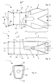
Figures 1-3 show a typical example of traditional reheat burner. - With reference to
figures 1-3 ,traditional burners 1 have aquadrangular channel 2 with alance 3 housed therein. - The
lance 3 has nozzles from which a fuel (either oil, i.e. liquid fuel, or gaseous fuel) is injected; as shown infigure 1 , the fuel is injected over a plane known asinjection plane 4. - The channel zone upstream of the injection plane 4 (in the direction of the hot gases G) is the
vortex generation zone 6; in thiszone vortex generators 7 are housed, projecting from each of the channel walls, to induce vortices and turbulence into the hot gases G. - The channel zone downstream of the injection plane 4 (in the hot gas direction G) is the
mixing zone 9. This zone has plane, divergingside walls 10, to define a diffuser, with an opening angle A relative to the channel longitudinal axis typically below 7 degree, to avoid flow separation from the inner surface of the side walls. - As shown in the figures, over the total channel length the
side walls 10 of thechannel 2 may converge or diverge to define a variable burner width w (measured at mid height), whereas the top andbottom walls 11 of thechannel 2 are parallel to each other, to define a constant burner height h. - The structure of the
burners 1 is optimised in order to achieve the best compromise of hot gas velocity and vortices and turbulence within thechannel 2 at the design temperature. - In fact, a high hot gas velocity through the
burner channel 2 reduces NOx emissions (since the residence time of the burning fuel in thecombustion chamber 12 downstream of theburner 1 is reduced) and increases the flashback margin (since it reduces the residence time of the fuel within thechannel 2 and thus it makes it more difficult for the fuel to achieve auto ignition) and reduces the water consumption in oil operation (water is mixed to oil to prevent flashback). - In contrast, high hot gas velocity increases the CO emissions (since the residence time in the
combustion chamber 12 downstream of theburner 1 is low) and pressure drop (i.e. efficiency and power achievable). - In addition, a high vortex and turbulence degree reduces the NOx and CO emissions (thanks to the good mixing), but it increases the pressure drop (thus it reduces efficiency and power achievable).
- In order to increase the gas turbine efficiency and performances, the temperature of the hot gases circulating through the
reheat burner 1 should be increased. - Such an increase causes the delicate equilibrium among all the parameters to be missed, such that a reheat burner operating with hot gases having a higher temperature than the design temperature may have flashback, NOx, CO emissions, water consumption and pressure drop problems.
- The technical aim of the present invention therefore includes providing a reheat burner addressing the aforementioned problems of the known art.
- Within the scope of this technical aim, an aspect of the invention is to provide a reheat burner that may safely operate without incurring in or with limited risks of flashback, NOx, CO emissions, water consumption and pressure drop problems, in particular when operating with hot gases having a temperatures higher than in traditional burners.
- The technical aim, together with these and further aspects, are attained according to the invention by providing a reheat burner in accordance with the accompanying claims.
- Further characteristics and advantages of the invention will be more apparent from the description of a preferred but non-exclusive embodiment of the reheat burner, illustrated by way of non-limiting example in the accompanying drawings, in which:
-
Figures 1, 2, 3 are respectively a top view, a side view and a front view of a traditional reheat burner; -
Figures 4, 5 and 6 are respectively a top view, a side view and a front view of a reheat burner in an embodiment of the invention; and -
Figure 7 is a top view of a further embodiment of the invention. - With reference to the figures, these show a
reheat burner 1, wherein like reference numerals designate identical or corresponding parts throughout the several views. - The
reheat burner 1 comprises achannel 2 with a quadrangular, square or trapezoidal cross section. - The
channel 2 has alance 3 projecting therein to inject a fuel over aninjection plane 4 perpendicular to a channellongitudinal axis 15. - The
channel 2 andlance 3 define avortex generation zone 6 upstream of theinjection plane 4 and amixing zone 9 downstream of theinjection plane 4 in the hot gas G direction. - The
mixing zone 9 has a quadrangular or trapezoidal or square cross section with divergingside walls 20 in the hot gas G direction. - The diverging
side walls 20 define curved surfaces in the hot gas G direction with a constant radius R centred in O. - In particular, the diverging
side walls 20 define the curved surfaces with said constant radius R in the hot gas G direction. - The diverging
side walls 20 may extend defining an angle A between their end and theaxis 15 larger than 8 degree and up to 15 degree or more. - In addition, the
channel 2 may also have the mixing zone terminal portion with divergingplane side walls 21 that are downstream of and flush with the diverging side walls 20 (figure 7 ). - When provided, also the diverging
plane side walls 21 define with the channellongitudinal axis 15 an angle A larger than 8 degree and up to 15 degree or also more. - The
curved side walls 20 and the large angle A allows the hot gas velocity to be strongly decreased without any flow separation risk, to increase the fuel/hot gas mixture residence time within thecombustion chamber 12 downstream of theburner 1 and, hence, reducing in particular the CO emissions. In addition, this large angle allows a large amount of the kinetic energy of the hot gases to be converted into static pressure, such that the total pressure drop through theburner 1 is very small. - In contrast, the top and
bottom walls 23 of themixing zone 9 between the divergingside walls vortex generation zone 6 is larger than at themixing zone 9. - Advantageously, the ratio between the width w at mid height and height h of the channel cross section at the
injection plane 4 is substantially equal to 1; this feature allows an optimised interaction between hot gases G flowing in thechannel 2 and the injected fuel, leading to an improved mixing quality between hot gases G and fuel and, thus, reduced emissions (in particular NOx emissions). - Downstream of the
injection plane 4 the mixing zone cross section decreases and then it increases again, defining athroat 24. - This feature allows a high hot gas velocity through the
channel 2, leading to a reduced residence time of the fuel (it is mixed with the hot gases G) in themixing section 9 and hence reduced flashback risk (or in other words increased safety margin against flashback); the reduced flashback risk in turn leads to a reduced water consumption in fuel oil operation (as known during fuel oil operation oil is mixed with water to increase the flashback safety margin). - The
lance tip 26 is located upstream of thethroat 24. - This feature ensures that the hot gas velocity increases up to a location downstream of the lance tip 26 (in the hot gas direction), preventing the flame from travelling upstream of the
lance tip 26 and, thus, further increasing the safety margin against flashback. - In a preferred embodiment, an
inner wall 27 of themixing zone 9 has aprotrusion 30 defining the line where the hot gases G detach from thewall 27. - This
protrusion 30 circumferentially extends over a plane perpendicular to a channellongitudinal axis 15. - The
vortex generation zone 6 has a section wherein both its width w and height h increase toward theinjection plane 4 to then decrease again. - This allows a large cross section to be available for the hot gases to pass through and limits the hot gas pressure drop through the
vortex generation zone 6. - In particular,
figures 4 through 6 show a first embodiment of the burner of the invention. - In this embodiment the
burner 1 has the width w and height h of thevortex generation zone 6 that increase toward theinjection plane 4 to then decrease again and amixing section 9 having only the diverging curved side walls 20 (i.e. no divergingplane side walls 21 are provided downstream of the curved side walls 20). For example the angle A between theside walls 20 and theaxis 15 is 16 degree. - In contrast,
figure 7 shows an embodiment of aburner 1 having the width w and height h of thevortex generation zone 6 that increase to then decrease again; in addition, themixing zone 9 has divergingcurved side walls 20 and, downstream of them, divergingplane side walls 21; in this case the angle A between the end of theside walls 20 and theaxis 15 is for example 14 degree and theplane side walls 21 maintain the same angle A over their whole length. - The operation of the burner of the invention is apparent from that described and illustrated and is substantially the following.
- The hot gases G generated in a combustion chamber (not shown) upstream of the
burner 1 and already partially expanded in a high pressure turbine (also not shown) enter thechannel 2 and pass through thevortex generation zone 6 where, thanks to thevortex generators 7, they increase their vortices and turbulence. The large cross section (thanks to the increasing width w and height h) allows small pressure drop. - Then a fuel (either oil or gaseous fuel) is injected into the hot gases G from the
lance 3. The particular cross section proportion of thechannel 2 at theinjection plane 4 allows optimised penetration of the fuel into the core of the vortices and mixing between fuel and hot gases G. In addition, since this zone converges, the hot gases G increase their velocity, hindering flashback. - Downstream of the
injection plane 4, the hot gases further increase their velocity, since thechannel 2 has a converging structure; then from the through 24 the hot gas velocity starts to decrease, because of the divergingside walls 20. - The particular structure with curved side walls 20 (with a preferred large radius R, for example larger than 500 millimetres) describing a circle arc in the top view ensures that the angle A in the burners in embodiments of the invention can be much larger than in traditional burners, since the hot gases G coming from the
throat 24 with a very high velocity can gradually decrease their velocity in a much larger extent than in traditional burners and without any risk of flow separation. - The large velocity decrease (thus the slow velocity at the entrance of the combustion chamber 12) allows the fuel/hot gas mixture residence time within the
combustion chamber 12 to be increased and, hence, the emissions and in particular the CO emissions to be reduced. - In addition, this large angle A allows a large amount of kinetic energy of the hot gases to be converted into static pressure, such that the total pressure drop through the burner is very small.
- When also the
plane side walls 21 are provided downstream of thecurved side walls 20, the length of thechannel 2 can be optimised to limit the curved side wall divergence and the maximum angle A to the desired amount. - Naturally the features described may be independently provided from one another.
- In practice the materials used and the dimensions can be chosen at will according to requirements and to the state of the art.
-
- 1
- burner
- 2
- channel
- 3
- lance
- 4
- injection plane
- 6
- vortex generation zone
- 7
- vortex generator
- 9
- mixing zone
- 10
- side wall
- 11
- top/bottom wall
- 12
- combustion chamber
- 15
- longitudinal axis of 2
- 20
- diverging curved side walls
- 21
- diverging plane side walls
- 23
- top and bottom sides
- 24
- throat
- 26
- lance tip
- 27
- inner wall of 9
- 30
- protrusion
- h
- height
- w
- width
- A
- angle
- G
- hot gases
- O
- centre of R
- R
- radius
Claims (13)
- Reheat burner (1) comprising a channel (2) with a lance (3) projecting thereinto to inject a fuel over an injection plane (4) perpendicular to a channel longitudinal axis (15), wherein the channel (2) and lance (3) define a vortex generation zone (6) upstream of the injection plane (4) and a mixing zone (9) downstream of the injection plane (4) in the hot gas (G) direction, wherein at least the mixing zone (9) has a cross section with diverging side walls (20) in the hot gas (G) direction, characterised in that the diverging side walls (20) define curved surfaces in the hot gas (G) direction having a constant radius (R).
- Reheat burner (1) as claimed in claim 1, characterised in that ends of the diverging side walls (20) define with the channel longitudinal axis (15) an angle (A) larger than 8 degree and preferably larger than 15 degree.
- Reheat burner (1) as claimed in claim 1, characterised in that the channel (2) has a mixing zone terminal portion with plane diverging side walls (21) downstream of the diverging side walls (20).
- Reheat burner (1) as claimed in claim 3, characterised in that the plane diverging side walls (21) are flush with the diverging side walls (20).
- Reheat burner (1) as claimed in claim 4, characterised in that the plane diverging side walls (21) define with the channel longitudinal axis (15) an angle (A) larger than 8 degree and preferably larger than 15 degree.
- Reheat burner (1) as claimed in claim 1, characterised in that the width (w) and height (h) of the vortex generation zone (6) increase toward the injection plane (4) to then decrease.
- Reheat burner (1) as claimed in claim 1, characterised in that at least those side walls (23) of the mixing zone (9) between the diverging side walls (20) define a constant mixing zone height (h).
- Reheat burner (1) as claimed in claim 1, characterised in that the ratio between the width (w) at mid height and height (h) of the channel cross section at the injection plane (4) is substantially equal to 1.
- Reheat burner (1) as claimed in claim 8, characterised in that downstream of the injection plane (4), the mixing zone cross section decreases and then it increases defining a throat (24).
- Reheat burner (1) as claimed in claim 9, characterised in that a lance tip (26) is located upstream of the throat (24).
- Reheat burner (1) as claimed in claim 1, characterised in that an inner wall (27) of the mixing zone (9) has a protrusion (30) defining the line where hot gases (G) detach from the walls.
- Reheat burner (1) as claimed in claim 11, characterised in that the protrusion (30) extends over a plane perpendicular to a channel axis (15).
- Reheat burner (1) as claimed in claim 1, characterised in that said channel (2) has a quadrangular, square or trapezoidal cross section.
Priority Applications (1)
| Application Number | Priority Date | Filing Date | Title |
|---|---|---|---|
| EP11175604.5A EP2420730B1 (en) | 2010-08-16 | 2011-07-27 | Reheat burner |
Applications Claiming Priority (2)
| Application Number | Priority Date | Filing Date | Title |
|---|---|---|---|
| EP10172900 | 2010-08-16 | ||
| EP11175604.5A EP2420730B1 (en) | 2010-08-16 | 2011-07-27 | Reheat burner |
Publications (3)
| Publication Number | Publication Date |
|---|---|
| EP2420730A2 true EP2420730A2 (en) | 2012-02-22 |
| EP2420730A3 EP2420730A3 (en) | 2015-06-24 |
| EP2420730B1 EP2420730B1 (en) | 2018-03-07 |
Family
ID=43719450
Family Applications (1)
| Application Number | Title | Priority Date | Filing Date |
|---|---|---|---|
| EP11175604.5A Not-in-force EP2420730B1 (en) | 2010-08-16 | 2011-07-27 | Reheat burner |
Country Status (2)
| Country | Link |
|---|---|
| US (1) | US9046265B2 (en) |
| EP (1) | EP2420730B1 (en) |
Cited By (1)
| Publication number | Priority date | Publication date | Assignee | Title |
|---|---|---|---|---|
| EP2693117A1 (en) | 2012-07-30 | 2014-02-05 | Alstom Technology Ltd | Reheat burner and method of mixing fuel/carrier air flow within a reheat burner |
Families Citing this family (1)
| Publication number | Priority date | Publication date | Assignee | Title |
|---|---|---|---|---|
| EP2725302A1 (en) * | 2012-10-25 | 2014-04-30 | Alstom Technology Ltd | Reheat burner arrangement |
Family Cites Families (8)
| Publication number | Priority date | Publication date | Assignee | Title |
|---|---|---|---|---|
| BE551418A (en) * | 1955-10-28 | |||
| IN170251B (en) | 1987-04-16 | 1992-03-07 | Luminis Pty Ltd | |
| DE4316474A1 (en) * | 1993-05-17 | 1994-11-24 | Abb Management Ag | Premix burner for operating an internal combustion engine, a combustion chamber of a gas turbine group or a combustion system |
| DE10026122A1 (en) * | 2000-05-26 | 2001-11-29 | Abb Alstom Power Nv | Burner for heat generator has shaping element with inner surface curving away from or towards burner axis; flow from mixing tube contacts inner surface and its spin rate increases |
| DE10128063A1 (en) * | 2001-06-09 | 2003-01-23 | Alstom Switzerland Ltd | burner system |
| GB2398375A (en) | 2003-02-14 | 2004-08-18 | Alstom | A mixer for two fluids having a venturi shape |
| ES2400247T3 (en) | 2008-12-19 | 2013-04-08 | Alstom Technology Ltd | Burner of a gas turbine that has a special lance configuration |
| EP2211109A1 (en) * | 2009-01-23 | 2010-07-28 | Alstom Technology Ltd | Burner of a gas turbine and method for mixing a fuel with a gaseous flow |
-
2011
- 2011-07-27 EP EP11175604.5A patent/EP2420730B1/en not_active Not-in-force
- 2011-08-08 US US13/205,146 patent/US9046265B2/en not_active Expired - Fee Related
Non-Patent Citations (1)
| Title |
|---|
| None |
Cited By (2)
| Publication number | Priority date | Publication date | Assignee | Title |
|---|---|---|---|---|
| EP2693117A1 (en) | 2012-07-30 | 2014-02-05 | Alstom Technology Ltd | Reheat burner and method of mixing fuel/carrier air flow within a reheat burner |
| US9541293B2 (en) | 2012-07-30 | 2017-01-10 | General Electric Technology Gmbh | Reheat burner and method of mixing fuel/carrier air flow within a reheat burner |
Also Published As
| Publication number | Publication date |
|---|---|
| EP2420730B1 (en) | 2018-03-07 |
| US9046265B2 (en) | 2015-06-02 |
| US20120047901A1 (en) | 2012-03-01 |
| EP2420730A3 (en) | 2015-06-24 |
Similar Documents
| Publication | Publication Date | Title |
|---|---|---|
| CN101201176B (en) | Fuel injection slot jet and method for enhancing mixing in premixing devices | |
| JP6335903B2 (en) | Flame sheet combustor dome | |
| EP2420731B1 (en) | Reheat burner | |
| US8490398B2 (en) | Premixed burner for a gas turbine combustor | |
| US8677756B2 (en) | Reheat burner injection system | |
| EP2400216A1 (en) | Lance of a reheat burner | |
| US11808457B2 (en) | Hydrogen injection for enhanced combustion stability in gas turbine systems | |
| EP2208934A1 (en) | Burner of a gas turbine for a reactive fuel air mixture | |
| KR20140052883A (en) | Reheat burner arrangement | |
| JP2010085087A (en) | Fuel lance for gas turbine engine | |
| EP2664854B1 (en) | Secondary combustion system | |
| EP2722591A1 (en) | Multiple cone gas turbine burner | |
| EP2211109A1 (en) | Burner of a gas turbine and method for mixing a fuel with a gaseous flow | |
| US12085282B2 (en) | Hydrogen injection for enhanced combustion stability in gas turbine systems | |
| CN116917667B (en) | Hydrogen injection for enhanced combustion stability in gas turbine systems | |
| EP2825823B1 (en) | Gas turbine combustion system and method of flame stabilization in such a system | |
| EP2420730B1 (en) | Reheat burner | |
| JP5574635B2 (en) | Swirl | |
| US20160252018A1 (en) | Enhanced mixing tube elements | |
| US8549860B2 (en) | Method for combusting hydrogen-rich, gaseous fuels in a burner, and burner for performing said method |
Legal Events
| Date | Code | Title | Description |
|---|---|---|---|
| AK | Designated contracting states |
Kind code of ref document: A2 Designated state(s): AL AT BE BG CH CY CZ DE DK EE ES FI FR GB GR HR HU IE IS IT LI LT LU LV MC MK MT NL NO PL PT RO RS SE SI SK SM TR |
|
| AX | Request for extension of the european patent |
Extension state: BA ME |
|
| PUAI | Public reference made under article 153(3) epc to a published international application that has entered the european phase |
Free format text: ORIGINAL CODE: 0009012 |
|
| PUAL | Search report despatched |
Free format text: ORIGINAL CODE: 0009013 |
|
| AK | Designated contracting states |
Kind code of ref document: A3 Designated state(s): AL AT BE BG CH CY CZ DE DK EE ES FI FR GB GR HR HU IE IS IT LI LT LU LV MC MK MT NL NO PL PT RO RS SE SI SK SM TR |
|
| AX | Request for extension of the european patent |
Extension state: BA ME |
|
| RIC1 | Information provided on ipc code assigned before grant |
Ipc: F23D 11/40 20060101ALI20150515BHEP Ipc: F23R 3/20 20060101ALI20150515BHEP Ipc: F23R 3/00 20060101ALI20150515BHEP Ipc: F23R 3/12 20060101ALI20150515BHEP Ipc: F23C 3/00 20060101AFI20150515BHEP |
|
| 17P | Request for examination filed |
Effective date: 20151222 |
|
| RBV | Designated contracting states (corrected) |
Designated state(s): AL AT BE BG CH CY CZ DE DK EE ES FI FR GB GR HR HU IE IS IT LI LT LU LV MC MK MT NL NO PL PT RO RS SE SI SK SM TR |
|
| RAP1 | Party data changed (applicant data changed or rights of an application transferred) |
Owner name: GENERAL ELECTRIC TECHNOLOGY GMBH |
|
| 17Q | First examination report despatched |
Effective date: 20161219 |
|
| RAP1 | Party data changed (applicant data changed or rights of an application transferred) |
Owner name: ANSALDO ENERGIA IP UK LIMITED |
|
| GRAP | Despatch of communication of intention to grant a patent |
Free format text: ORIGINAL CODE: EPIDOSNIGR1 |
|
| INTG | Intention to grant announced |
Effective date: 20170914 |
|
| GRAS | Grant fee paid |
Free format text: ORIGINAL CODE: EPIDOSNIGR3 |
|
| GRAA | (expected) grant |
Free format text: ORIGINAL CODE: 0009210 |
|
| AK | Designated contracting states |
Kind code of ref document: B1 Designated state(s): AL AT BE BG CH CY CZ DE DK EE ES FI FR GB GR HR HU IE IS IT LI LT LU LV MC MK MT NL NO PL PT RO RS SE SI SK SM TR |
|
| REG | Reference to a national code |
Ref country code: GB Ref legal event code: FG4D |
|
| REG | Reference to a national code |
Ref country code: CH Ref legal event code: EP Ref country code: AT Ref legal event code: REF Ref document number: 976965 Country of ref document: AT Kind code of ref document: T Effective date: 20180315 |
|
| REG | Reference to a national code |
Ref country code: IE Ref legal event code: FG4D |
|
| REG | Reference to a national code |
Ref country code: DE Ref legal event code: R096 Ref document number: 602011046207 Country of ref document: DE |
|
| REG | Reference to a national code |
Ref country code: NL Ref legal event code: MP Effective date: 20180307 |
|
| REG | Reference to a national code |
Ref country code: LT Ref legal event code: MG4D |
|
| PG25 | Lapsed in a contracting state [announced via postgrant information from national office to epo] |
Ref country code: NO Free format text: LAPSE BECAUSE OF FAILURE TO SUBMIT A TRANSLATION OF THE DESCRIPTION OR TO PAY THE FEE WITHIN THE PRESCRIBED TIME-LIMIT Effective date: 20180607 Ref country code: ES Free format text: LAPSE BECAUSE OF FAILURE TO SUBMIT A TRANSLATION OF THE DESCRIPTION OR TO PAY THE FEE WITHIN THE PRESCRIBED TIME-LIMIT Effective date: 20180307 Ref country code: HR Free format text: LAPSE BECAUSE OF FAILURE TO SUBMIT A TRANSLATION OF THE DESCRIPTION OR TO PAY THE FEE WITHIN THE PRESCRIBED TIME-LIMIT Effective date: 20180307 Ref country code: LT Free format text: LAPSE BECAUSE OF FAILURE TO SUBMIT A TRANSLATION OF THE DESCRIPTION OR TO PAY THE FEE WITHIN THE PRESCRIBED TIME-LIMIT Effective date: 20180307 Ref country code: CY Free format text: LAPSE BECAUSE OF FAILURE TO SUBMIT A TRANSLATION OF THE DESCRIPTION OR TO PAY THE FEE WITHIN THE PRESCRIBED TIME-LIMIT Effective date: 20180307 Ref country code: FI Free format text: LAPSE BECAUSE OF FAILURE TO SUBMIT A TRANSLATION OF THE DESCRIPTION OR TO PAY THE FEE WITHIN THE PRESCRIBED TIME-LIMIT Effective date: 20180307 |
|
| REG | Reference to a national code |
Ref country code: AT Ref legal event code: MK05 Ref document number: 976965 Country of ref document: AT Kind code of ref document: T Effective date: 20180307 |
|
| PG25 | Lapsed in a contracting state [announced via postgrant information from national office to epo] |
Ref country code: GR Free format text: LAPSE BECAUSE OF FAILURE TO SUBMIT A TRANSLATION OF THE DESCRIPTION OR TO PAY THE FEE WITHIN THE PRESCRIBED TIME-LIMIT Effective date: 20180608 Ref country code: SE Free format text: LAPSE BECAUSE OF FAILURE TO SUBMIT A TRANSLATION OF THE DESCRIPTION OR TO PAY THE FEE WITHIN THE PRESCRIBED TIME-LIMIT Effective date: 20180307 Ref country code: LV Free format text: LAPSE BECAUSE OF FAILURE TO SUBMIT A TRANSLATION OF THE DESCRIPTION OR TO PAY THE FEE WITHIN THE PRESCRIBED TIME-LIMIT Effective date: 20180307 Ref country code: RS Free format text: LAPSE BECAUSE OF FAILURE TO SUBMIT A TRANSLATION OF THE DESCRIPTION OR TO PAY THE FEE WITHIN THE PRESCRIBED TIME-LIMIT Effective date: 20180307 Ref country code: BG Free format text: LAPSE BECAUSE OF FAILURE TO SUBMIT A TRANSLATION OF THE DESCRIPTION OR TO PAY THE FEE WITHIN THE PRESCRIBED TIME-LIMIT Effective date: 20180607 |
|
| PG25 | Lapsed in a contracting state [announced via postgrant information from national office to epo] |
Ref country code: EE Free format text: LAPSE BECAUSE OF FAILURE TO SUBMIT A TRANSLATION OF THE DESCRIPTION OR TO PAY THE FEE WITHIN THE PRESCRIBED TIME-LIMIT Effective date: 20180307 Ref country code: IT Free format text: LAPSE BECAUSE OF FAILURE TO SUBMIT A TRANSLATION OF THE DESCRIPTION OR TO PAY THE FEE WITHIN THE PRESCRIBED TIME-LIMIT Effective date: 20180307 Ref country code: PL Free format text: LAPSE BECAUSE OF FAILURE TO SUBMIT A TRANSLATION OF THE DESCRIPTION OR TO PAY THE FEE WITHIN THE PRESCRIBED TIME-LIMIT Effective date: 20180307 Ref country code: AL Free format text: LAPSE BECAUSE OF FAILURE TO SUBMIT A TRANSLATION OF THE DESCRIPTION OR TO PAY THE FEE WITHIN THE PRESCRIBED TIME-LIMIT Effective date: 20180307 Ref country code: RO Free format text: LAPSE BECAUSE OF FAILURE TO SUBMIT A TRANSLATION OF THE DESCRIPTION OR TO PAY THE FEE WITHIN THE PRESCRIBED TIME-LIMIT Effective date: 20180307 Ref country code: NL Free format text: LAPSE BECAUSE OF FAILURE TO SUBMIT A TRANSLATION OF THE DESCRIPTION OR TO PAY THE FEE WITHIN THE PRESCRIBED TIME-LIMIT Effective date: 20180307 |
|
| PG25 | Lapsed in a contracting state [announced via postgrant information from national office to epo] |
Ref country code: AT Free format text: LAPSE BECAUSE OF FAILURE TO SUBMIT A TRANSLATION OF THE DESCRIPTION OR TO PAY THE FEE WITHIN THE PRESCRIBED TIME-LIMIT Effective date: 20180307 Ref country code: CZ Free format text: LAPSE BECAUSE OF FAILURE TO SUBMIT A TRANSLATION OF THE DESCRIPTION OR TO PAY THE FEE WITHIN THE PRESCRIBED TIME-LIMIT Effective date: 20180307 Ref country code: SK Free format text: LAPSE BECAUSE OF FAILURE TO SUBMIT A TRANSLATION OF THE DESCRIPTION OR TO PAY THE FEE WITHIN THE PRESCRIBED TIME-LIMIT Effective date: 20180307 Ref country code: SM Free format text: LAPSE BECAUSE OF FAILURE TO SUBMIT A TRANSLATION OF THE DESCRIPTION OR TO PAY THE FEE WITHIN THE PRESCRIBED TIME-LIMIT Effective date: 20180307 |
|
| REG | Reference to a national code |
Ref country code: DE Ref legal event code: R097 Ref document number: 602011046207 Country of ref document: DE |
|
| PG25 | Lapsed in a contracting state [announced via postgrant information from national office to epo] |
Ref country code: PT Free format text: LAPSE BECAUSE OF FAILURE TO SUBMIT A TRANSLATION OF THE DESCRIPTION OR TO PAY THE FEE WITHIN THE PRESCRIBED TIME-LIMIT Effective date: 20180709 |
|
| PLBE | No opposition filed within time limit |
Free format text: ORIGINAL CODE: 0009261 |
|
| STAA | Information on the status of an ep patent application or granted ep patent |
Free format text: STATUS: NO OPPOSITION FILED WITHIN TIME LIMIT |
|
| PG25 | Lapsed in a contracting state [announced via postgrant information from national office to epo] |
Ref country code: DK Free format text: LAPSE BECAUSE OF FAILURE TO SUBMIT A TRANSLATION OF THE DESCRIPTION OR TO PAY THE FEE WITHIN THE PRESCRIBED TIME-LIMIT Effective date: 20180307 |
|
| REG | Reference to a national code |
Ref country code: DE Ref legal event code: R119 Ref document number: 602011046207 Country of ref document: DE |
|
| 26N | No opposition filed |
Effective date: 20181210 |
|
| PG25 | Lapsed in a contracting state [announced via postgrant information from national office to epo] |
Ref country code: SI Free format text: LAPSE BECAUSE OF FAILURE TO SUBMIT A TRANSLATION OF THE DESCRIPTION OR TO PAY THE FEE WITHIN THE PRESCRIBED TIME-LIMIT Effective date: 20180307 |
|
| REG | Reference to a national code |
Ref country code: CH Ref legal event code: PL |
|
| GBPC | Gb: european patent ceased through non-payment of renewal fee |
Effective date: 20180727 |
|
| PG25 | Lapsed in a contracting state [announced via postgrant information from national office to epo] |
Ref country code: LU Free format text: LAPSE BECAUSE OF NON-PAYMENT OF DUE FEES Effective date: 20180727 Ref country code: MC Free format text: LAPSE BECAUSE OF FAILURE TO SUBMIT A TRANSLATION OF THE DESCRIPTION OR TO PAY THE FEE WITHIN THE PRESCRIBED TIME-LIMIT Effective date: 20180307 |
|
| REG | Reference to a national code |
Ref country code: BE Ref legal event code: MM Effective date: 20180731 |
|
| PG25 | Lapsed in a contracting state [announced via postgrant information from national office to epo] |
Ref country code: FR Free format text: LAPSE BECAUSE OF NON-PAYMENT OF DUE FEES Effective date: 20180731 Ref country code: GB Free format text: LAPSE BECAUSE OF NON-PAYMENT OF DUE FEES Effective date: 20180727 Ref country code: CH Free format text: LAPSE BECAUSE OF NON-PAYMENT OF DUE FEES Effective date: 20180731 Ref country code: LI Free format text: LAPSE BECAUSE OF NON-PAYMENT OF DUE FEES Effective date: 20180731 Ref country code: DE Free format text: LAPSE BECAUSE OF NON-PAYMENT OF DUE FEES Effective date: 20190201 |
|
| REG | Reference to a national code |
Ref country code: IE Ref legal event code: MM4A |
|
| PG25 | Lapsed in a contracting state [announced via postgrant information from national office to epo] |
Ref country code: BE Free format text: LAPSE BECAUSE OF NON-PAYMENT OF DUE FEES Effective date: 20180731 |
|
| PG25 | Lapsed in a contracting state [announced via postgrant information from national office to epo] |
Ref country code: IE Free format text: LAPSE BECAUSE OF NON-PAYMENT OF DUE FEES Effective date: 20180727 |
|
| PG25 | Lapsed in a contracting state [announced via postgrant information from national office to epo] |
Ref country code: MT Free format text: LAPSE BECAUSE OF NON-PAYMENT OF DUE FEES Effective date: 20180727 |
|
| PG25 | Lapsed in a contracting state [announced via postgrant information from national office to epo] |
Ref country code: TR Free format text: LAPSE BECAUSE OF FAILURE TO SUBMIT A TRANSLATION OF THE DESCRIPTION OR TO PAY THE FEE WITHIN THE PRESCRIBED TIME-LIMIT Effective date: 20180307 |
|
| PG25 | Lapsed in a contracting state [announced via postgrant information from national office to epo] |
Ref country code: HU Free format text: LAPSE BECAUSE OF FAILURE TO SUBMIT A TRANSLATION OF THE DESCRIPTION OR TO PAY THE FEE WITHIN THE PRESCRIBED TIME-LIMIT; INVALID AB INITIO Effective date: 20110727 |
|
| PG25 | Lapsed in a contracting state [announced via postgrant information from national office to epo] |
Ref country code: MK Free format text: LAPSE BECAUSE OF NON-PAYMENT OF DUE FEES Effective date: 20180307 |
|
| PG25 | Lapsed in a contracting state [announced via postgrant information from national office to epo] |
Ref country code: IS Free format text: LAPSE BECAUSE OF FAILURE TO SUBMIT A TRANSLATION OF THE DESCRIPTION OR TO PAY THE FEE WITHIN THE PRESCRIBED TIME-LIMIT Effective date: 20180707 |