EP2420630A1 - Improved Waste Trap - Google Patents
Improved Waste Trap Download PDFInfo
- Publication number
- EP2420630A1 EP2420630A1 EP11250546A EP11250546A EP2420630A1 EP 2420630 A1 EP2420630 A1 EP 2420630A1 EP 11250546 A EP11250546 A EP 11250546A EP 11250546 A EP11250546 A EP 11250546A EP 2420630 A1 EP2420630 A1 EP 2420630A1
- Authority
- EP
- European Patent Office
- Prior art keywords
- trap
- waste
- outlet
- weir
- inlet
- Prior art date
- Legal status (The legal status is an assumption and is not a legal conclusion. Google has not performed a legal analysis and makes no representation as to the accuracy of the status listed.)
- Granted
Links
Images


Classifications
-
- E—FIXED CONSTRUCTIONS
- E03—WATER SUPPLY; SEWERAGE
- E03C—DOMESTIC PLUMBING INSTALLATIONS FOR FRESH WATER OR WASTE WATER; SINKS
- E03C1/00—Domestic plumbing installations for fresh water or waste water; Sinks
- E03C1/12—Plumbing installations for waste water; Basins or fountains connected thereto; Sinks
- E03C1/28—Odour seals
- E03C1/29—Odour seals having housing containing dividing wall, e.g. tubular
-
- E—FIXED CONSTRUCTIONS
- E03—WATER SUPPLY; SEWERAGE
- E03C—DOMESTIC PLUMBING INSTALLATIONS FOR FRESH WATER OR WASTE WATER; SINKS
- E03C1/00—Domestic plumbing installations for fresh water or waste water; Sinks
- E03C1/12—Plumbing installations for waste water; Basins or fountains connected thereto; Sinks
-
- E—FIXED CONSTRUCTIONS
- E03—WATER SUPPLY; SEWERAGE
- E03C—DOMESTIC PLUMBING INSTALLATIONS FOR FRESH WATER OR WASTE WATER; SINKS
- E03C1/00—Domestic plumbing installations for fresh water or waste water; Sinks
- E03C1/12—Plumbing installations for waste water; Basins or fountains connected thereto; Sinks
- E03C1/14—Wash-basins connected to the waste-pipe
-
- E—FIXED CONSTRUCTIONS
- E03—WATER SUPPLY; SEWERAGE
- E03C—DOMESTIC PLUMBING INSTALLATIONS FOR FRESH WATER OR WASTE WATER; SINKS
- E03C1/00—Domestic plumbing installations for fresh water or waste water; Sinks
- E03C1/12—Plumbing installations for waste water; Basins or fountains connected thereto; Sinks
- E03C1/20—Connecting baths or bidets to the wastepipe
-
- E—FIXED CONSTRUCTIONS
- E03—WATER SUPPLY; SEWERAGE
- E03C—DOMESTIC PLUMBING INSTALLATIONS FOR FRESH WATER OR WASTE WATER; SINKS
- E03C1/00—Domestic plumbing installations for fresh water or waste water; Sinks
- E03C1/12—Plumbing installations for waste water; Basins or fountains connected thereto; Sinks
- E03C1/28—Odour seals
-
- E—FIXED CONSTRUCTIONS
- E03—WATER SUPPLY; SEWERAGE
- E03F—SEWERS; CESSPOOLS
- E03F5/00—Sewerage structures
- E03F5/04—Gullies inlets, road sinks, floor drains with or without odour seals or sediment traps
- E03F5/0407—Floor drains for indoor use
- E03F5/0408—Floor drains for indoor use specially adapted for showers
Definitions
- the present invention relates to waste traps. Particularly, but not exclusively, the present invention relates to a waste trap for a bath.
- a waste trap is generally provided between a bath outlet and a soil pipe to allow water from the bath to reach the soil pipe but to prevent, for example, noxious gases in the waste system entering the bathroom through the bath outlet.
- the waste trap provides a barrier between the soil pipe and the bath outlet in the form of a water seal.
- a waste trap will have some sort of convoluted flow path which fills with water to a fixed depth sealing the bath outlet and the overflow outlet from the ingress of waste gases.
- a waste trap for a bath comprising:
- providing a waste trap in which the height of the water seal is higher than at least part of the trap outlet reduces the overall height of the trap, allowing the trap to be installed in smaller spaces than a conventional trap.
- the trap may be arranged to form a water seal between the second trap inlet and the trap outlet, the height of the water seal, in use, being higher than at least part of the trap outlet
- the trap may comprise a body.
- the body may define the first trap inlet, the second trap inlet and the trap outlet.
- the body may define a first convoluted flow path between the first trap inlet and the trap outlet.
- the body may define a second convoluted flow path between the second trap inlet and the trap outlet.
- the trap may include a weir.
- the weir may have an upper edge higher than at least part of the trap outlet.
- the height of the water seal is determined by the upper edge of the weir.
- the height of the water seal in relation to the trap outlet can be raised and the overall depth of the water trap can be reduced. Furthermore by raising the water seal in relation to the trap outlet permits for a larger diameter of trap outlet to be accommodated without affecting the overall height of the trap and further improving the volume flow rate through the trap.
- the weir is arranged such that water flows up and over the weir before flowing through the trap outlet.
- the trap body comprises a first portion, defining the first trap inlet and the second trap inlet, and a second portion defining the trap outlet.
- the second body portion maybe rotatably mounted to the first body portion.
- Such an arrangement adds flexibility to the waste trap as the second body portion can be moved with respect to the first body portion to accommodate different plumbing arrangements which may exist.
- the weir may be defined by the first body portion.
- the weir may be defined by the second body portion.
- the weir may be an insert.
- the weir may be tubular.
- the second body portion may be rotatably mounted to the tubular weir.
- the second body portion may be adapted to be rotated by a tool.
- the second body portion may define a feature adapted to be engaged by a tool.
- the feature may be a recess adapted to receive, for example, a screwdriver or a coin.
- the second body portion may comprise a chamber.
- the chamber may comprise an upper section and a lower section.
- the upper section may be spin welded to the lower section.
- the upper section may define a feature adapted to be engaged by a tool to permit the chamber to be rotated with respect to the weir.
- the chamber may be adapted to receive the weir.
- the chamber may comprise a tubular portion of larger diameter than the tubular weir.
- providing a chamber permits water flowing over the weir to flow into the chamber before exiting through the outlet. This maintains the volume flow rate of the trap by preventing a bottleneck between the weir and the trap outlet.
- the weir may be spaced away from the outlet. If the weir is spaced away from the outlet, then the weir does not reduce the effective size of the outlet, maximising the volume flow rate through the outlet.
- a chamber upper external surface is coplanar with the first trap inlet.
- the trap body may be moulded.
- the trap body may comprise a polymeric material.
- the polymeric material may be polypropylene.
- polymeric material may be any suitable material such as polycarbonate.
- a bath trap generally indicated by reference numeral 10, is shown.
- the bath trap 10 comprises a first trap inlet 12, connected to the outlet 14 of a bath 15, a second trap inlet 16 connected to a bath overflow 18 and a trap outlet 20 connected to a waste pipe 22 (not visible on figure 1 but shown in broken outline on figure 3 ).
- the trap 10 is shown sandwiched between the bath and the floor 17.
- the trap 10 is arranged to form a water seal 24 between the first trap inlet 12 and the trap outlet 20, the height 26 of the water seal 24 being higher than at least part of the trap outlet 20.
- the height of the water seal, indicated by the broken line 26 is higher than the majority of the trap outlet 20 and particularly, the water seal 24 is higher than the portion of the trap outlet 20 shown in broken outline.
- water seal 24 formed between the second trap inlet 16, the overflow pipe 18 and the trap outlet 20 is also higher than at least part of the trap outlet 20, and particularly, the water seal 24 is higher than the portion of the trap outlet 20 shown in broken outline.
- the trap 10 comprises a body 32 having a first body portion 34 and a second body portion 36.
- the first body portion 34 is moulded from polypropylene and defines the first trap inlet 12, the second trap inlet 16 and the tubular weir 28.
- the second body portion 36 is also moulded from polypropylene and is rotatably mounted to the first body portion 34.
- the second body portion 36 defines a chamber 38 for receiving water flowing over the weir 28.
- the chamber 38 is of larger internal diameter than the external diameter of the tubular weir 28 and is in fluid communication with trap outlet 20, which is also defined by the second body portion 36.
- the second body portion 36 is locked to the first body portion 34 by complementary engaging lug and recess arrangement 40 about which the second body portion 36 can rotate with respect to the first body portion 34. Allowing the second body portion 36 to rotate facilitates fitting the trap and particularly connecting the trap outlet 20 to the waste pipe 22, thereby increasing the utility of the trap 10.
- a watertight seal is formed between the first and second body sections 34, 36 by an elastomeric seal 42.
- the second body portion is manufactured in two parts, a lower half 44 and a lid 46.
- the lid 46 is spun welded to the second body portion lower half 44.
- the lid 46 defines a cross hair recess 48 adapted to receive a tool (not shown) which can rotate the second body portion 36 with respect of the first body portion 34.
- the tool may be a coin or a screwdriver, for example. Rotatably mounting the second body portion 36 to the first body portion 34 increases the flexibility and utility of the trap 10.
- the trap inlet 12 comprises a threaded sleeve 50 attached to the first body portion 34 by an adhesive.
- the threaded sleeve 50 defines an internal thread 52 and includes a flange 54.
- the flange 54 is adapted to receive an elastomeric seal gasket 56.
- the trap 10 is secured to the bath 30 by locating the first inlet 12, and particularly the flanging gasket 54, 56 adjacent the bath outlet 14.
- a joining member 58 defining an external thread 60, is then screwed into the threaded sleeve 50.
- the engagement between the threaded sleeve 50 and the joining member 58 draws the two components together until the bath outlet 14 is trapped between the joining member 58 and the inlet piece 50 and a seal is formed between the bath outlet 14 and the gasket 56.
- the lid 46 of the second body portion 36 could be removable to facilitate adjustment or cleaning of the trap 10.
Landscapes
- Engineering & Computer Science (AREA)
- Health & Medical Sciences (AREA)
- Life Sciences & Earth Sciences (AREA)
- Hydrology & Water Resources (AREA)
- Public Health (AREA)
- Water Supply & Treatment (AREA)
- Environmental & Geological Engineering (AREA)
- Sink And Installation For Waste Water (AREA)
Abstract
Description
- The present invention relates to waste traps. Particularly, but not exclusively, the present invention relates to a waste trap for a bath.
- A waste trap is generally provided between a bath outlet and a soil pipe to allow water from the bath to reach the soil pipe but to prevent, for example, noxious gases in the waste system entering the bathroom through the bath outlet.
- The waste trap provides a barrier between the soil pipe and the bath outlet in the form of a water seal. Generally such a waste trap will have some sort of convoluted flow path which fills with water to a fixed depth sealing the bath outlet and the overflow outlet from the ingress of waste gases.
- Regulations state that the water seal has to be a minimum depth of 50 millimetres. The depth of the trap itself is therefore determined by the minimum depth of the water seal plus the diameter of the waste pipe.
- Current fashions in bath design are for baths which are as close to the floor as possible and there is a desire to minimise the gap between the base of the bath on the floor. However, current designs of waste trap cannot be accommodated in the reduced spaces which the bath designers specify. In some instances, this results in a hole or recess being made in the floor to accommodate the waste trap.
- It is known to try and reduce the height of the trap by using a reduced diameter connection from the trap to the soil pipe, however this can have a detrimental effect on the flow rate through the trap.
- According to a first aspect of the present invention there is provided a waste trap for a bath, the trap comprising:
- a first trap inlet adapted to be connected to a bath outlet;
- a second trap inlet adapted to be connected to a bath overflow; and
- a trap outlet adapted to be connected to a waste pipe;
- wherein the trap is arranged to form a water seal between the first trap inlet and the trap outlet, the height of the water seal, in use, being higher than at least part of the trap outlet.
- In one embodiment, providing a waste trap in which the height of the water seal is higher than at least part of the trap outlet reduces the overall height of the trap, allowing the trap to be installed in smaller spaces than a conventional trap.
- Additionally, the trap may be arranged to form a water seal between the second trap inlet and the trap outlet, the height of the water seal, in use, being higher than at least part of the trap outlet
- The trap may comprise a body.
- The body may define the first trap inlet, the second trap inlet and the trap outlet.
- The body may define a first convoluted flow path between the first trap inlet and the trap outlet.
- The body may define a second convoluted flow path between the second trap inlet and the trap outlet.
- The trap may include a weir.
- The weir may have an upper edge higher than at least part of the trap outlet.
- In one embodiment the height of the water seal is determined by the upper edge of the weir. By incorporating a weir, the height of the water seal in relation to the trap outlet can be raised and the overall depth of the water trap can be reduced. Furthermore by raising the water seal in relation to the trap outlet permits for a larger diameter of trap outlet to be accommodated without affecting the overall height of the trap and further improving the volume flow rate through the trap.
- In one embodiment the weir is arranged such that water flows up and over the weir before flowing through the trap outlet.
- In one embodiment the trap body comprises a first portion, defining the first trap inlet and the second trap inlet, and a second portion defining the trap outlet.
- In this embodiment, the second body portion maybe rotatably mounted to the first body portion. Such an arrangement adds flexibility to the waste trap as the second body portion can be moved with respect to the first body portion to accommodate different plumbing arrangements which may exist.
- The weir may be defined by the first body portion.
- Alternatively, the weir may be defined by the second body portion.
- In a further alternative, the weir may be an insert.
- In an embodiment, the weir may be tubular.
- In this embodiment, the second body portion may be rotatably mounted to the tubular weir.
- The second body portion may be adapted to be rotated by a tool.
- The second body portion may define a feature adapted to be engaged by a tool.
- The feature may be a recess adapted to receive, for example, a screwdriver or a coin.
- The second body portion may comprise a chamber.
- The chamber may comprise an upper section and a lower section.
- The upper section may be spin welded to the lower section. The upper section may define a feature adapted to be engaged by a tool to permit the chamber to be rotated with respect to the weir.
- The chamber may be adapted to receive the weir.
- Where the weir is tubular, the chamber may comprise a tubular portion of larger diameter than the tubular weir.
- In one embodiment providing a chamber permits water flowing over the weir to flow into the chamber before exiting through the outlet. This maintains the volume flow rate of the trap by preventing a bottleneck between the weir and the trap outlet.
- The weir may be spaced away from the outlet. If the weir is spaced away from the outlet, then the weir does not reduce the effective size of the outlet, maximising the volume flow rate through the outlet.
- In one embodiment a chamber upper external surface is coplanar with the first trap inlet.
- The trap body may be moulded.
- The trap body may comprise a polymeric material.
- The polymeric material may be polypropylene.
- Alternatively polymeric material may be any suitable material such as polycarbonate.
- An embodiment of the present invention will now be described with reference to the accompanying drawings in which:
-
Figure 1 is a section view through a waste trap for a bath, shown in use with a bath, according to a first embodiment of the present invention; -
Figure 2 is a front view of the trap ofFigure 1 ; -
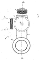
Figure 3 is a top view of the trap ofFigure 1 . - Referring to the figures, a bath trap, generally indicated by reference numeral 10, is shown. The bath trap 10 comprises a
first trap inlet 12, connected to theoutlet 14 of a bath 15, a second trap inlet 16 connected to a bath overflow 18 and atrap outlet 20 connected to a waste pipe 22 (not visible onfigure 1 but shown in broken outline onfigure 3 ). The trap 10 is shown sandwiched between the bath and thefloor 17. - The trap 10 is arranged to form a
water seal 24 between thefirst trap inlet 12 and thetrap outlet 20, theheight 26 of thewater seal 24 being higher than at least part of thetrap outlet 20. As can be seen fromfigure 1 , the height of the water seal, indicated by thebroken line 26, is higher than the majority of thetrap outlet 20 and particularly, thewater seal 24 is higher than the portion of thetrap outlet 20 shown in broken outline. - It will also be noted that the
water seal 24 formed between the second trap inlet 16, the overflow pipe 18 and thetrap outlet 20 is also higher than at least part of thetrap outlet 20, and particularly, thewater seal 24 is higher than the portion of thetrap outlet 20 shown in broken outline. - Such an arrangement reduces the overall height of the trap 10 allowing the trap 10 to be installed in smaller spaces than a conventional trap. This reduction in height is made possible by the provision of a
tubular weir 28 which is situated adjacent thetrap outlet 20. - The trap 10 comprises a body 32 having a
first body portion 34 and asecond body portion 36. Thefirst body portion 34 is moulded from polypropylene and defines thefirst trap inlet 12, the second trap inlet 16 and thetubular weir 28. Thesecond body portion 36 is also moulded from polypropylene and is rotatably mounted to thefirst body portion 34. Thesecond body portion 36 defines a chamber 38 for receiving water flowing over theweir 28. The chamber 38 is of larger internal diameter than the external diameter of thetubular weir 28 and is in fluid communication withtrap outlet 20, which is also defined by thesecond body portion 36. - The
second body portion 36 is locked to thefirst body portion 34 by complementary engaging lug and recess arrangement 40 about which thesecond body portion 36 can rotate with respect to thefirst body portion 34. Allowing thesecond body portion 36 to rotate facilitates fitting the trap and particularly connecting thetrap outlet 20 to the waste pipe 22, thereby increasing the utility of the trap 10. - A watertight seal is formed between the first and
second body sections - The second body portion is manufactured in two parts, a lower half 44 and a
lid 46. Thelid 46 is spun welded to the second body portion lower half 44. As can be seen most clearly fromfigure 3 , thelid 46 defines a cross hair recess 48 adapted to receive a tool (not shown) which can rotate thesecond body portion 36 with respect of thefirst body portion 34. The tool may be a coin or a screwdriver, for example. Rotatably mounting thesecond body portion 36 to thefirst body portion 34 increases the flexibility and utility of the trap 10. - Referring back to
figure 1 , thetrap inlet 12 comprises a threaded sleeve 50 attached to thefirst body portion 34 by an adhesive. The threaded sleeve 50 defines an internal thread 52 and includes aflange 54. Theflange 54 is adapted to receive an elastomeric seal gasket 56. In use, the trap 10 is secured to thebath 30 by locating thefirst inlet 12, and particularly theflanging gasket 54, 56 adjacent thebath outlet 14. A joining member 58, defining an external thread 60, is then screwed into the threaded sleeve 50. The engagement between the threaded sleeve 50 and the joining member 58 draws the two components together until thebath outlet 14 is trapped between the joining member 58 and the inlet piece 50 and a seal is formed between thebath outlet 14 and the gasket 56. - Various modifications and improvements may be made to the above described embodiment without departing from the scope of the invention. For example, the
lid 46 of thesecond body portion 36 could be removable to facilitate adjustment or cleaning of the trap 10.
Claims (32)
- A waste trap for a bath, the trap comprising:a first trap inlet adapted to be connected to a bath outlet;a second trap inlet adapted to be connected to a bath overflow; anda trap outlet adapted to be connected to a waste pipe;wherein the trap is arranged to form a water seal between the first trap inlet and the trap outlet, the height of the water seal, in use, being higher than at least part of the trap outlet.
- The waste trap of claim 1, wherein the trap is arranged to form a water seal between the second trap inlet and the trap outlet, the height of the water seal, in use, being higher than at least part of the trap outlet
- The waste trap of either of claims 1 or 2, wherein the trap comprises a body.
- The waste trap of claim 3, wherein the body defines the first trap inlet, the second trap inlet and the trap outlet.
- The waste trap of claim 4, wherein the body defines a first convoluted flow path between the first trap inlet and the trap outlet.
- The waste trap of either of claims 4 or 5, wherein the body defines a second convoluted flow path between the second trap inlet and the trap outlet.
- The waste trap of any preceding claim, wherein the trap includes a weir.
- The waste trap of claim 7, wherein the weir has an upper edge higher than at least part of the trap outlet.
- The waste trap of claim 8, wherein the height of the water seal is determined by the upper edge of the weir.
- The waste trap of any of claims 7 to 9, wherein the weir is arranged such that water flows up and over the weir before flowing through the trap outlet.
- The waste trap of any of claims 7 to 10, wherein the trap body comprises a first portion, defining the first trap inlet and the second trap inlet, and a second portion defining the trap outlet.
- The waste trap of claim 11, wherein the second body portion is rotatably mounted to the first body portion.
- The waste trap of either of claims 11 or 12, wherein the weir is defined by the first body portion.
- The waste trap of either of claims 11 or 12, wherein the weir is defined by the second body portion.
- The waste trap of any of claims 11 to 13, wherein the weir is an insert.
- The waste trap of any of claims 11 to 14, wherein the weir is tubular.
- The waste trap of claim 16, wherein the second body portion is rotatably mounted to the tubular weir.
- The waste trap of claim 17, wherein the second body portion is adapted to be rotated by a tool.
- The waste trap of claim 18, wherein the second body portion defines a feature adapted to be engaged by a tool.
- The waste trap of claim 19, wherein the feature is a recess adapted to receive, for example, a screwdriver or a coin.
- The waste trap of any of claims 11 to 20, wherein the second body portion comprises a chamber.
- The waste trap of claim 21, wherein the chamber comprises an upper section and a lower section.
- The waste trap of claim 22, wherein the upper section is spin welded to the lower section.
- The waste trap of either of claims 22 or 23, wherein the upper section defines a feature adapted to be engaged by a tool to permit the chamber to be rotated with respect to the weir.
- The waste trap of any of claims 21 to 24, wherein the chamber is adapted to receive the weir.
- The waste trap of claim 25, wherein where the weir is tubular, the chamber comprises a tubular portion of larger diameter than the tubular weir.
- The waste trap of either of claims 25 or 26, wherein the weir is spaced away from the outlet.
- The waste trap of any of claims 25 to 27, wherein a chamber upper external surface is coplanar with the first trap inlet.
- The waste trap of any proceeding claim, wherein the trap body is moulded.
- The waste trap of any proceeding claim, wherein the trap body comprises a polymeric material.
- The waste trap of claim 30, wherein the polymeric material is polypropylene.
- The waste trap of claim 30, wherein the polymeric material is any suitable material such as polycarbonate.
Applications Claiming Priority (1)
| Application Number | Priority Date | Filing Date | Title |
|---|---|---|---|
| GB1008558.7A GB2480604B (en) | 2010-05-24 | 2010-05-24 | Waste trap |
Publications (3)
| Publication Number | Publication Date |
|---|---|
| EP2420630A1 true EP2420630A1 (en) | 2012-02-22 |
| EP2420630C0 EP2420630C0 (en) | 2023-11-29 |
| EP2420630B1 EP2420630B1 (en) | 2023-11-29 |
Family
ID=42341159
Family Applications (1)
| Application Number | Title | Priority Date | Filing Date |
|---|---|---|---|
| EP11250546.6A Active EP2420630B1 (en) | 2010-05-24 | 2011-05-24 | Improved Waste Trap |
Country Status (3)
| Country | Link |
|---|---|
| EP (1) | EP2420630B1 (en) |
| GB (1) | GB2480604B (en) |
| PL (1) | PL2420630T3 (en) |
Citations (3)
| Publication number | Priority date | Publication date | Assignee | Title |
|---|---|---|---|---|
| US497465A (en) * | 1893-05-16 | Overflow | ||
| DE102005011790B3 (en) * | 2005-03-11 | 2006-11-23 | Franz Kaldewei Gmbh & Co Kg | Drain for sanitary tub has recess in base of tub with lower pipe fitting and cover flush with floor of tub |
| DE102008023894A1 (en) * | 2007-09-25 | 2009-04-02 | Desch, Kurt Michael, Dipl.-Ing. (FH) | Bathtub-base inlet, has lower side of upper horizontal channel of stopper is moved up and down, where horizontal channel is immersed in diameter of screw, and bath water flow cross-section is always more sufficient with respect to flow hole |
Family Cites Families (3)
| Publication number | Priority date | Publication date | Assignee | Title |
|---|---|---|---|---|
| JP4842021B2 (en) * | 2006-06-14 | 2011-12-21 | 株式会社ブリヂストン | Drain trap |
| DE202008004826U1 (en) * | 2008-04-07 | 2009-08-20 | Viega Gmbh & Co. Kg | Drain fitting for bath or shower trays with bottom inlet |
| JP2011094304A (en) * | 2009-10-27 | 2011-05-12 | Maruichi Corp | Drain trap |
-
2010
- 2010-05-24 GB GB1008558.7A patent/GB2480604B/en active Active
-
2011
- 2011-05-24 PL PL11250546.6T patent/PL2420630T3/en unknown
- 2011-05-24 EP EP11250546.6A patent/EP2420630B1/en active Active
Patent Citations (3)
| Publication number | Priority date | Publication date | Assignee | Title |
|---|---|---|---|---|
| US497465A (en) * | 1893-05-16 | Overflow | ||
| DE102005011790B3 (en) * | 2005-03-11 | 2006-11-23 | Franz Kaldewei Gmbh & Co Kg | Drain for sanitary tub has recess in base of tub with lower pipe fitting and cover flush with floor of tub |
| DE102008023894A1 (en) * | 2007-09-25 | 2009-04-02 | Desch, Kurt Michael, Dipl.-Ing. (FH) | Bathtub-base inlet, has lower side of upper horizontal channel of stopper is moved up and down, where horizontal channel is immersed in diameter of screw, and bath water flow cross-section is always more sufficient with respect to flow hole |
Also Published As
| Publication number | Publication date |
|---|---|
| EP2420630C0 (en) | 2023-11-29 |
| GB201008558D0 (en) | 2010-07-07 |
| PL2420630T3 (en) | 2024-04-22 |
| EP2420630B1 (en) | 2023-11-29 |
| GB2480604B (en) | 2015-03-18 |
| GB2480604A (en) | 2011-11-30 |
Similar Documents
| Publication | Publication Date | Title |
|---|---|---|
| US20100251477A1 (en) | Rim overflow | |
| KR101520292B1 (en) | Vacuum breaker, automatic flushing system for toilet and electronic bidet toilet having the same | |
| RU2383690C2 (en) | Water seal for sanitary ware | |
| CA2845558A1 (en) | Strainer with improved flow | |
| EP3002377A1 (en) | Floor drain with siphon | |
| JP5703824B2 (en) | Drain trap | |
| US20130081203A1 (en) | Tub overflow assembly | |
| JP4709981B2 (en) | Drain trap | |
| EP2778303A1 (en) | Anti-siphonic toilet | |
| JP2008261222A (en) | Public fence backflow prevention device and public fence | |
| CA2786186C (en) | Trap seal primer device | |
| EP2420630B1 (en) | Improved Waste Trap | |
| EP2206841A2 (en) | Siphon accessible to plumbing snake via feed opening | |
| CN101824844A (en) | Sink and sink overflow device | |
| JP6019287B2 (en) | Drain trap | |
| JP2019214912A (en) | Drain port member and drain piping structure | |
| US20060076300A1 (en) | System and method for reducing runoff of grease and similar effluents from restaurants and like facilites | |
| CN210713076U (en) | Three-way drainage pipe fitting of kitchen garbage disposer | |
| JP6060327B2 (en) | Drain trap | |
| JP6072426B2 (en) | urinal | |
| CN109868886B (en) | Floor drain assembly for washing machine | |
| JP3271748B2 (en) | 90 ° elbow trap | |
| CN201704749U (en) | Plug for intercepting litters | |
| JP4795786B2 (en) | Drainage with trap | |
| JP2007039956A (en) | Drainage trap structure of bathroom |
Legal Events
| Date | Code | Title | Description |
|---|---|---|---|
| AK | Designated contracting states |
Kind code of ref document: A1 Designated state(s): AL AT BE BG CH CY CZ DE DK EE ES FI FR GB GR HR HU IE IS IT LI LT LU LV MC MK MT NL NO PL PT RO RS SE SI SK SM TR |
|
| AX | Request for extension of the european patent |
Extension state: BA ME |
|
| PUAI | Public reference made under article 153(3) epc to a published international application that has entered the european phase |
Free format text: ORIGINAL CODE: 0009012 |
|
| 17P | Request for examination filed |
Effective date: 20120821 |
|
| 17Q | First examination report despatched |
Effective date: 20130523 |
|
| STAA | Information on the status of an ep patent application or granted ep patent |
Free format text: STATUS: EXAMINATION IS IN PROGRESS |
|
| GRAP | Despatch of communication of intention to grant a patent |
Free format text: ORIGINAL CODE: EPIDOSNIGR1 |
|
| STAA | Information on the status of an ep patent application or granted ep patent |
Free format text: STATUS: GRANT OF PATENT IS INTENDED |
|
| INTG | Intention to grant announced |
Effective date: 20221205 |
|
| GRAJ | Information related to disapproval of communication of intention to grant by the applicant or resumption of examination proceedings by the epo deleted |
Free format text: ORIGINAL CODE: EPIDOSDIGR1 |
|
| STAA | Information on the status of an ep patent application or granted ep patent |
Free format text: STATUS: EXAMINATION IS IN PROGRESS |
|
| INTC | Intention to grant announced (deleted) | ||
| GRAP | Despatch of communication of intention to grant a patent |
Free format text: ORIGINAL CODE: EPIDOSNIGR1 |
|
| STAA | Information on the status of an ep patent application or granted ep patent |
Free format text: STATUS: GRANT OF PATENT IS INTENDED |
|
| INTG | Intention to grant announced |
Effective date: 20230606 |
|
| GRAS | Grant fee paid |
Free format text: ORIGINAL CODE: EPIDOSNIGR3 |
|
| GRAA | (expected) grant |
Free format text: ORIGINAL CODE: 0009210 |
|
| STAA | Information on the status of an ep patent application or granted ep patent |
Free format text: STATUS: THE PATENT HAS BEEN GRANTED |
|
| RBV | Designated contracting states (corrected) |
Designated state(s): AL AT BE BG CH CY CZ DE DK EE ES FI FR GR HR HU IE IS IT LI LT LU LV MC MK MT NL NO PL PT RO RS SE SI SK SM TR |
|
| AK | Designated contracting states |
Kind code of ref document: B1 Designated state(s): AL AT BE BG CH CY CZ DE DK EE ES FI FR GR HR HU IE IS IT LI LT LU LV MC MK MT NL NO PL PT RO RS SE SI SK SM TR |
|
| RIN1 | Information on inventor provided before grant (corrected) |
Inventor name: MCALPINE, JAMES EDWARD |
|
| REG | Reference to a national code |
Ref country code: CH Ref legal event code: EP |
|
| REG | Reference to a national code |
Ref country code: DE Ref legal event code: R096 Ref document number: 602011074436 Country of ref document: DE |
|
| REG | Reference to a national code |
Ref country code: IE Ref legal event code: FG4D |
|
| U01 | Request for unitary effect filed |
Effective date: 20231228 |
|
| U07 | Unitary effect registered |
Designated state(s): AT BE BG DE DK EE FI FR IT LT LU LV MT NL PT SE SI Effective date: 20240110 |
|
| PG25 | Lapsed in a contracting state [announced via postgrant information from national office to epo] |
Ref country code: GR Free format text: LAPSE BECAUSE OF FAILURE TO SUBMIT A TRANSLATION OF THE DESCRIPTION OR TO PAY THE FEE WITHIN THE PRESCRIBED TIME-LIMIT Effective date: 20240301 |
|
| PG25 | Lapsed in a contracting state [announced via postgrant information from national office to epo] |
Ref country code: IS Free format text: LAPSE BECAUSE OF FAILURE TO SUBMIT A TRANSLATION OF THE DESCRIPTION OR TO PAY THE FEE WITHIN THE PRESCRIBED TIME-LIMIT Effective date: 20240329 |
|
| PG25 | Lapsed in a contracting state [announced via postgrant information from national office to epo] |
Ref country code: ES Free format text: LAPSE BECAUSE OF FAILURE TO SUBMIT A TRANSLATION OF THE DESCRIPTION OR TO PAY THE FEE WITHIN THE PRESCRIBED TIME-LIMIT Effective date: 20231129 |
|
| PG25 | Lapsed in a contracting state [announced via postgrant information from national office to epo] |
Ref country code: IS Free format text: LAPSE BECAUSE OF FAILURE TO SUBMIT A TRANSLATION OF THE DESCRIPTION OR TO PAY THE FEE WITHIN THE PRESCRIBED TIME-LIMIT Effective date: 20240329 Ref country code: GR Free format text: LAPSE BECAUSE OF FAILURE TO SUBMIT A TRANSLATION OF THE DESCRIPTION OR TO PAY THE FEE WITHIN THE PRESCRIBED TIME-LIMIT Effective date: 20240301 Ref country code: ES Free format text: LAPSE BECAUSE OF FAILURE TO SUBMIT A TRANSLATION OF THE DESCRIPTION OR TO PAY THE FEE WITHIN THE PRESCRIBED TIME-LIMIT Effective date: 20231129 |
|
| PG25 | Lapsed in a contracting state [announced via postgrant information from national office to epo] |
Ref country code: RS Free format text: LAPSE BECAUSE OF FAILURE TO SUBMIT A TRANSLATION OF THE DESCRIPTION OR TO PAY THE FEE WITHIN THE PRESCRIBED TIME-LIMIT Effective date: 20231129 Ref country code: NO Free format text: LAPSE BECAUSE OF FAILURE TO SUBMIT A TRANSLATION OF THE DESCRIPTION OR TO PAY THE FEE WITHIN THE PRESCRIBED TIME-LIMIT Effective date: 20240229 Ref country code: HR Free format text: LAPSE BECAUSE OF FAILURE TO SUBMIT A TRANSLATION OF THE DESCRIPTION OR TO PAY THE FEE WITHIN THE PRESCRIBED TIME-LIMIT Effective date: 20231129 |
|
| U20 | Renewal fee for the european patent with unitary effect paid |
Year of fee payment: 14 Effective date: 20240531 |
|
| PG25 | Lapsed in a contracting state [announced via postgrant information from national office to epo] |
Ref country code: CZ Free format text: LAPSE BECAUSE OF FAILURE TO SUBMIT A TRANSLATION OF THE DESCRIPTION OR TO PAY THE FEE WITHIN THE PRESCRIBED TIME-LIMIT Effective date: 20231129 |
|
| PG25 | Lapsed in a contracting state [announced via postgrant information from national office to epo] |
Ref country code: SK Free format text: LAPSE BECAUSE OF FAILURE TO SUBMIT A TRANSLATION OF THE DESCRIPTION OR TO PAY THE FEE WITHIN THE PRESCRIBED TIME-LIMIT Effective date: 20231129 |
|
| PG25 | Lapsed in a contracting state [announced via postgrant information from national office to epo] |
Ref country code: SM Free format text: LAPSE BECAUSE OF FAILURE TO SUBMIT A TRANSLATION OF THE DESCRIPTION OR TO PAY THE FEE WITHIN THE PRESCRIBED TIME-LIMIT Effective date: 20231129 Ref country code: SK Free format text: LAPSE BECAUSE OF FAILURE TO SUBMIT A TRANSLATION OF THE DESCRIPTION OR TO PAY THE FEE WITHIN THE PRESCRIBED TIME-LIMIT Effective date: 20231129 Ref country code: RO Free format text: LAPSE BECAUSE OF FAILURE TO SUBMIT A TRANSLATION OF THE DESCRIPTION OR TO PAY THE FEE WITHIN THE PRESCRIBED TIME-LIMIT Effective date: 20231129 Ref country code: CZ Free format text: LAPSE BECAUSE OF FAILURE TO SUBMIT A TRANSLATION OF THE DESCRIPTION OR TO PAY THE FEE WITHIN THE PRESCRIBED TIME-LIMIT Effective date: 20231129 |
|
| REG | Reference to a national code |
Ref country code: DE Ref legal event code: R097 Ref document number: 602011074436 Country of ref document: DE |
|
| PLBE | No opposition filed within time limit |
Free format text: ORIGINAL CODE: 0009261 |
|
| STAA | Information on the status of an ep patent application or granted ep patent |
Free format text: STATUS: NO OPPOSITION FILED WITHIN TIME LIMIT |
|
| 26N | No opposition filed |
Effective date: 20240830 |
|
| REG | Reference to a national code |
Ref country code: CH Ref legal event code: PL |
|
| PG25 | Lapsed in a contracting state [announced via postgrant information from national office to epo] |
Ref country code: MC Free format text: LAPSE BECAUSE OF FAILURE TO SUBMIT A TRANSLATION OF THE DESCRIPTION OR TO PAY THE FEE WITHIN THE PRESCRIBED TIME-LIMIT Effective date: 20231129 |
|
| PG25 | Lapsed in a contracting state [announced via postgrant information from national office to epo] |
Ref country code: MC Free format text: LAPSE BECAUSE OF FAILURE TO SUBMIT A TRANSLATION OF THE DESCRIPTION OR TO PAY THE FEE WITHIN THE PRESCRIBED TIME-LIMIT Effective date: 20231129 Ref country code: CH Free format text: LAPSE BECAUSE OF NON-PAYMENT OF DUE FEES Effective date: 20240531 |
|
| PG25 | Lapsed in a contracting state [announced via postgrant information from national office to epo] |
Ref country code: IE Free format text: LAPSE BECAUSE OF NON-PAYMENT OF DUE FEES Effective date: 20240524 |
|
| U20 | Renewal fee for the european patent with unitary effect paid |
Year of fee payment: 15 Effective date: 20250527 |
|
| PG25 | Lapsed in a contracting state [announced via postgrant information from national office to epo] |
Ref country code: CY Free format text: LAPSE BECAUSE OF FAILURE TO SUBMIT A TRANSLATION OF THE DESCRIPTION OR TO PAY THE FEE WITHIN THE PRESCRIBED TIME-LIMIT; INVALID AB INITIO Effective date: 20110524 |
|
| PG25 | Lapsed in a contracting state [announced via postgrant information from national office to epo] |
Ref country code: HU Free format text: LAPSE BECAUSE OF FAILURE TO SUBMIT A TRANSLATION OF THE DESCRIPTION OR TO PAY THE FEE WITHIN THE PRESCRIBED TIME-LIMIT; INVALID AB INITIO Effective date: 20110524 |
|
| U1N | Appointed representative for the unitary patent procedure changed after the registration of the unitary effect |
Representative=s name: MARKS & CLERK LLP; GB |
|
| U20 | Renewal fee for the european patent with unitary effect paid |
Year of fee payment: 16 Effective date: 20260529 |
|
| PGFP | Annual fee paid to national office [announced via postgrant information from national office to epo] |
Ref country code: PL Payment date: 20260505 Year of fee payment: 16 |
|
| PGFP | Annual fee paid to national office [announced via postgrant information from national office to epo] |
Ref country code: TR Payment date: 20260513 Year of fee payment: 16 |