EP2420449A1 - Drug feeder and drug delivery unit - Google Patents
Drug feeder and drug delivery unit Download PDFInfo
- Publication number
- EP2420449A1 EP2420449A1 EP10764531A EP10764531A EP2420449A1 EP 2420449 A1 EP2420449 A1 EP 2420449A1 EP 10764531 A EP10764531 A EP 10764531A EP 10764531 A EP10764531 A EP 10764531A EP 2420449 A1 EP2420449 A1 EP 2420449A1
- Authority
- EP
- European Patent Office
- Prior art keywords
- rotation
- gear
- rotor
- medicine
- reverse
- Prior art date
- Legal status (The legal status is an assumption and is not a legal conclusion. Google has not performed a legal analysis and makes no representation as to the accuracy of the status listed.)
- Withdrawn
Links
- 239000003814 drug Substances 0.000 title claims abstract description 78
- 229940079593 drug Drugs 0.000 title description 6
- 238000012377 drug delivery Methods 0.000 title 1
- 230000005540 biological transmission Effects 0.000 claims abstract description 122
- 238000001514 detection method Methods 0.000 claims abstract description 27
- 230000009467 reduction Effects 0.000 claims description 11
- 230000003287 optical effect Effects 0.000 claims description 3
- 239000003826 tablet Substances 0.000 description 60
- 238000000034 method Methods 0.000 description 16
- 230000008569 process Effects 0.000 description 14
- 230000008878 coupling Effects 0.000 description 6
- 238000010168 coupling process Methods 0.000 description 6
- 238000005859 coupling reaction Methods 0.000 description 6
- 238000010586 diagram Methods 0.000 description 5
- 230000006870 function Effects 0.000 description 3
- 238000005259 measurement Methods 0.000 description 3
- 238000000638 solvent extraction Methods 0.000 description 2
- 239000002775 capsule Substances 0.000 description 1
- 230000008859 change Effects 0.000 description 1
- 238000007796 conventional method Methods 0.000 description 1
- 230000004069 differentiation Effects 0.000 description 1
- 239000007947 dispensing tablet Substances 0.000 description 1
- 238000003780 insertion Methods 0.000 description 1
- 230000037431 insertion Effects 0.000 description 1
- WABPQHHGFIMREM-UHFFFAOYSA-N lead(0) Chemical compound [Pb] WABPQHHGFIMREM-UHFFFAOYSA-N 0.000 description 1
- 230000000149 penetrating effect Effects 0.000 description 1
- 229940126589 solid medicine Drugs 0.000 description 1
Images










Classifications
-
- B—PERFORMING OPERATIONS; TRANSPORTING
- B65—CONVEYING; PACKING; STORING; HANDLING THIN OR FILAMENTARY MATERIAL
- B65B—MACHINES, APPARATUS OR DEVICES FOR, OR METHODS OF, PACKAGING ARTICLES OR MATERIALS; UNPACKING
- B65B1/00—Packaging fluent solid material, e.g. powders, granular or loose fibrous material, loose masses of small articles, in individual containers or receptacles, e.g. bags, sacks, boxes, cartons, cans, or jars
- B65B1/04—Methods of, or means for, filling the material into the containers or receptacles
- B65B1/10—Methods of, or means for, filling the material into the containers or receptacles by rotary feeders
-
- G—PHYSICS
- G07—CHECKING-DEVICES
- G07F—COIN-FREED OR LIKE APPARATUS
- G07F11/00—Coin-freed apparatus for dispensing, or the like, discrete articles
- G07F11/02—Coin-freed apparatus for dispensing, or the like, discrete articles from non-movable magazines
- G07F11/44—Coin-freed apparatus for dispensing, or the like, discrete articles from non-movable magazines in which magazines the articles are stored in bulk
-
- B—PERFORMING OPERATIONS; TRANSPORTING
- B65—CONVEYING; PACKING; STORING; HANDLING THIN OR FILAMENTARY MATERIAL
- B65B—MACHINES, APPARATUS OR DEVICES FOR, OR METHODS OF, PACKAGING ARTICLES OR MATERIALS; UNPACKING
- B65B1/00—Packaging fluent solid material, e.g. powders, granular or loose fibrous material, loose masses of small articles, in individual containers or receptacles, e.g. bags, sacks, boxes, cartons, cans, or jars
- B65B1/30—Devices or methods for controlling or determining the quantity or quality or the material fed or filled
-
- B—PERFORMING OPERATIONS; TRANSPORTING
- B65—CONVEYING; PACKING; STORING; HANDLING THIN OR FILAMENTARY MATERIAL
- B65B—MACHINES, APPARATUS OR DEVICES FOR, OR METHODS OF, PACKAGING ARTICLES OR MATERIALS; UNPACKING
- B65B37/00—Supplying or feeding fluent-solid, plastic, or liquid material, or loose masses of small articles, to be packaged
- B65B37/08—Supplying or feeding fluent-solid, plastic, or liquid material, or loose masses of small articles, to be packaged by rotary feeders
-
- B—PERFORMING OPERATIONS; TRANSPORTING
- B65—CONVEYING; PACKING; STORING; HANDLING THIN OR FILAMENTARY MATERIAL
- B65B—MACHINES, APPARATUS OR DEVICES FOR, OR METHODS OF, PACKAGING ARTICLES OR MATERIALS; UNPACKING
- B65B57/00—Automatic control, checking, warning, or safety devices
-
- B—PERFORMING OPERATIONS; TRANSPORTING
- B65—CONVEYING; PACKING; STORING; HANDLING THIN OR FILAMENTARY MATERIAL
- B65B—MACHINES, APPARATUS OR DEVICES FOR, OR METHODS OF, PACKAGING ARTICLES OR MATERIALS; UNPACKING
- B65B57/00—Automatic control, checking, warning, or safety devices
- B65B57/18—Automatic control, checking, warning, or safety devices causing operation of audible or visible alarm signals
-
- B—PERFORMING OPERATIONS; TRANSPORTING
- B65—CONVEYING; PACKING; STORING; HANDLING THIN OR FILAMENTARY MATERIAL
- B65B—MACHINES, APPARATUS OR DEVICES FOR, OR METHODS OF, PACKAGING ARTICLES OR MATERIALS; UNPACKING
- B65B57/00—Automatic control, checking, warning, or safety devices
- B65B57/20—Applications of counting devices for controlling the feed of articles
-
- B—PERFORMING OPERATIONS; TRANSPORTING
- B65—CONVEYING; PACKING; STORING; HANDLING THIN OR FILAMENTARY MATERIAL
- B65B—MACHINES, APPARATUS OR DEVICES FOR, OR METHODS OF, PACKAGING ARTICLES OR MATERIALS; UNPACKING
- B65B65/00—Details peculiar to packaging machines and not otherwise provided for; Arrangements of such details
- B65B65/02—Driving gear
-
- G—PHYSICS
- G07—CHECKING-DEVICES
- G07F—COIN-FREED OR LIKE APPARATUS
- G07F11/00—Coin-freed apparatus for dispensing, or the like, discrete articles
- G07F11/005—Special arrangements for insuring that only one single article may be dispensed at a time
-
- G—PHYSICS
- G07—CHECKING-DEVICES
- G07F—COIN-FREED OR LIKE APPARATUS
- G07F17/00—Coin-freed apparatus for hiring articles; Coin-freed facilities or services
- G07F17/0092—Coin-freed apparatus for hiring articles; Coin-freed facilities or services for assembling and dispensing of pharmaceutical articles
-
- G—PHYSICS
- G07—CHECKING-DEVICES
- G07F—COIN-FREED OR LIKE APPARATUS
- G07F9/00—Details other than those peculiar to special kinds or types of apparatus
- G07F9/02—Devices for alarm or indication, e.g. when empty; Advertising arrangements in coin-freed apparatus
- G07F9/026—Devices for alarm or indication, e.g. when empty; Advertising arrangements in coin-freed apparatus for alarm, monitoring and auditing in vending machines or means for indication, e.g. when empty
Definitions
- control operations by the control circuit 61 will be described based on flowcharts in Fig. 14 through Fig. 16 .
- the male spline 89 is tapered on its both end portions as shown in Fig. 24B so that the male spline 89 can make smooth engagement with the female spline 88 upon a reciprocal movement of the slide shaft 83 over a predetermined stroke L.
- the slide shaft 83 has a tip, and this tip is pressed by a pivot arm 93 which is moved by the switching motor 39.
- the pivot arm 93 pivots by a predetermined angle from a state drawn in solid lines in the Fig. 23 , the slide shaft 83 is moved axially by a predetermined stroke L, disengaging the male spline 89 from the female spline 88 in the output gear 86, and engaging it with the female spline 88 in the output gear 91.
- the drive unit described thus far according to the third embodiment is coupled with the dispensing cassette 16 to constitute the earlier-described medicine feeder 13 like in the first and the second embodiments, and is mounted in the medicine dispenser 11.
- a control block diagram and a flowchart for this embodiment are the same as in Fig. 13 through Fig. 16 .
Landscapes
- Physics & Mathematics (AREA)
- General Physics & Mathematics (AREA)
- Engineering & Computer Science (AREA)
- Mechanical Engineering (AREA)
- Business, Economics & Management (AREA)
- Accounting & Taxation (AREA)
- Quality & Reliability (AREA)
- Basic Packing Technique (AREA)
- Medical Preparation Storing Or Oral Administration Devices (AREA)
- Gear Transmission (AREA)
Abstract
Description
- The present invention relates to a medicine feeder for storing tablets, capsules or other solid-type medicines by the kind and dispensing these medicines one by one in predetermined numbers based on prescribing information. The invention also relates to a medicine dispenser including a plurality of the medicine feeders.
- A dispenser of solid medicines (hereinafter simply called "tablet(s)", includes a predetermined number of cassette-type medicine feeders for dispensing tablets one by one. In the medicine feeder, a medicine storage has a bottom provided with a rotor. The rotor has an outer circumferential surface formed with a large number of pockets, and as the rotor rotates, tablets in the medicine storage are dispensed one by one from a dispensing spout (Patent Document 1).
- In this dispensing process in the medicine dispenser, there are cases where a tablet is jammed to seize and disable the rotor from rotation due to a trouble caused by, for example, the shape of the tablet or the tablet's attitude at the time of entering the pocket in the outer circumference of the rotor.
- When jamming of a tablet is detected, the state of clogging can be cleared by a known method: Upon detection of an overcurrent to a DC motor which drives the rotor, a determination is made that the motor has been locked by a jammed tablet and the motor is driven in a reverse direction momentarily (Patent Document 2).
- Another known method is counting the quantity of tablets being dispensed and reversing the rotor momentarily upon a determination that the counting within a predetermined period of time gives a smaller number than predetermined due to a jammed tablet (Patent Document 3).
- In whichever of the cases, reverse rotation of the rotor is achieved by inverting the polarity of electric current supplied to the motor.
-
- Patent Document 1: Japanese Patent Laid-Open No.
2005-289506 - Patent Document 2: Japanese Patent Laid-Open No.
2000-103404 - Patent Document 3: Japanese Patent No.
3895989 - However, reversing the motor rotation by inverting the polarity of the motor current as used in the conventional methods in order to reverse the rotation of the rotor has a problem since the motor is subjected to a strong torque at the time of reversing the rotation, and repeating such a cycle of normal-and-reverse rotations will lead to a problem of reduced life of the motor.
- It is therefore an object of the present invention to solve the problem of jammed tablet in medicine feeders and in a medicine dispenser including the medicine feeders, through improvements on a motor drive unit which drives the rotor of the dispensing cassettes so that reverse rotation of the rotor can be achieved without rotating the motor in reverse, i.e. by reversing only the rotor while the motor remains in normal rotation setting, in cases where a jammed tablet is detected.
- In order to solve the above-described problem, the present invention includes an aspect relating to a medicine feeder, and offers a medicine feeder which is provided by a combination of a dispensing cassette and a drive unit. The dispensing cassette includes a medicine storage for storing medicine, and a rotor at a bottom portion of the medicine storage. The drive unit includes a drive motor, a gear transmission device, an output shaft and a switcher. The gear transmission device has a normal-rotation transmission path and a reverse-rotation transmission path constituted by gear trains between a motor shaft of the drive motor and the output shaft. The switcher selects one of the transmission paths for an output of driving power from the drive motor to the dispensing cassette.
- In the medicine feeder described above, when the drive unit drives the dispensing cassette, the drive power is transmitted via the normal-rotation transmission path, thereby driving the rotor in a normal rotation direction, to dispense a tablet. Upon detection of a trouble such as a jammed tablet, the switcher switches the drive power transmission path to the reverse-rotation transmission path, whereby the motor remains in normal rotation setting but the rotor is driven in a reverse rotation direction in an attempt to clear the jammed tablet.
- Also, in order to solve the above-described problem, the present invention includes an aspect relating to a medicine dispenser, and offers a medicine dispenser which includes a predetermined number of medicine feeders, a control circuit and a display device. The medicine feeder is provided by a combination of a medicine dispensing cassette and a drive unit. The dispensing cassette includes a medicine storage for storing medicine, and a rotor at a bottom portion of the medicine storage. The drive unit includes a drive motor, a gear transmission device, an output shaft, a switcher, a tablet counting sensor and a rotor-rotation detection sensor. The gear transmission device has a normal-rotation transmission path and a reverse-rotation transmission path between a motor shaft of the drive motor and the output shaft. The switcher selects one of the transmission paths for an output of driving power from the drive motor to the dispensing cassette. Upon detection of a stoppage of the rotor based on a signal from the rotor-rotation detection sensor, the control circuit controls the drive unit for reverse rotation of the rotor for a predetermined period of time followed by resumption to normal rotation.
- As described, in cases where a tablet is jammed, the medicine feeder and the medicine dispenser according to the present invention are capable of attempting to clear the jammed tablet by driving the rotor in a reverse rotation direction without making the drive motor rotate in a reverse rotation direction. Since the motor is not driven in reverse rotation direction, the motor can work under a reduced burden, and can have an extended life according to the present invention.
-
-
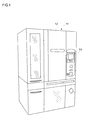
Fig. 1 is a perspective view of a medicine dispenser according to a first embodiment. -
Fig. 2 is a sectional view of the medicine feeder. -
Fig. 3 is a perspective view of a vertical section of a rotor region in the medicine feeder. -
Fig. 4 is a simplified plan view of a horizontal section taken in lines X1-X1 inFig. 2 . -
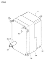
Fig. 5 is a perspective view of a drive unit. -
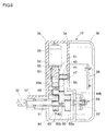
Fig. 6 is a sectional view taken in lines X2-X2 inFig. 5 . -
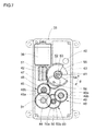
Fig. 7 is a sectional view taken in lines X3-X3 inFig. 6 . -
Fig. 8 is an schematic illustration of a gear train in normal rotation transmission. -
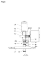
Fig. 9 is a side view of a vertical section taken inFig. 8 . -
Fig. 10 is an explanatory drawing of a gear train in reverse rotation transmission. -
Fig. 11 is a side view of a vertical section taken inFig. 10 . -
Fig. 12 is a front view of a rotor-rotation detection sensor. -
Fig. 13 is a control block diagram of the medicine dispenser according to the first embodiment. -
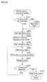
Fig. 14 is a flowchart for the first embodiment. -
Fig. 15 is a flowchart for the first embodiment, for normal rotation of the rotor. -
Fig. 16 is a flowchart for the first embodiment, for reverse rotation of the rotor. -
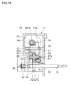
Fig. 17 is a sectional view of a drive unit according to a second embodiment. -
Fig. 18 is a sectional view taken in lines X4-X4 inFig. 17 . -
Fig. 19 is an explanatory drawing of a gear train in normal rotation transmission. -
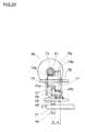
Fig. 20 is a side view of a vertical section taken inFig. 19 . -
Fig. 21 is an explanatory drawing of a gear train in reverse rotation transmission. -
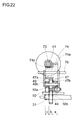
Fig. 22 is a side view of a vertical section taken inFig. 20 . -
Fig. 23 is a simplified sectional view of a third embodiment. -
Fig. 24A is an enlarged sectional view of a clutch region in -
Fig. 23 . -
Fig. 24B is an enlarged partial plan view of a male spline in -
Fig. 23 . -
Fig. 25 is a simplified sectional view of a fourth embodiment. - Hereinafter, embodiments of the present invention will be described based on the attached drawings.
- As shown in
Fig. 1 , amedicine dispenser 11 according to a first embodiment incorporates a large number of medicine feeders 13 (seeFig. 2 ) behind afront door 12. Also, anoperation display panel 14 is provided on the right of thedoor 12. - As shown in
Fig. 2 , themedicine feeder 13 is composed of a dispensingcassette 16 and adrive unit 17. The dispensingcassette 16 is conventional (see Patent Document 1), and includes amedicine storage 18 which stores tablets, arotor 19 provided at a bottom of themedicine storage 18, agear transmission section 21 provided at a bottom surface of themedicine storage 18, and other components. - Drive power from the
drive unit 17 is transmitted via thegear transmission section 21 to rotate therotor 19, and in this rotation, tablets T (seeFig. 3 ) in themedicine storage 18 are distributed intopockets 22 between a large number ofvertical ribs 20 provided in an outer circumferential surface of therotor 19. Near a dispensingspout 23, a partitioningmember 24, which is like a comb having elastic bristle teeth, is inserted from aslit 24a across thepocket 22 as indicated by Arrow "a", so that there is only one tablet T below the partitioningmember 24. This singularly isolated tablet T is dispensed into a container or the like upon coming to the dispensingspout 23. The dispensingspout 23 is provided with an optical,tablet counting sensor 25 which includes a light emitter and a light receiver. - The
gear transmission section 21 is composed of aworm gear 27 attached to aninput shaft 26; aworm ring 28 engaged therewith; and arotor gear 29 engaged with theworm ring 28. In the case shown in the Figure, theworm gear 27 has a right-hand helix (seeFig. 4 ). Theinput shaft 26 is connectable with and disconnectable from an output shaft 31 (seeFig. 4 ) of thedrive unit 17 viacouplings -
Fig. 4 shows rotation directions of thegears Fig. 2 . In the Figure, Arrow A indicates clockwise rotation, i.e., normal rotation, whereas Arrow B indicates counterclockwise rotation, i.e., reverse rotation. The Figure shows a dispensing state in which therotor gear 29 makes normal rotation, causing normal rotation of arotor shaft 30 and therotor 19 integral therewith. - In this case, when the
input shaft 26 makes reverse rotation, theworm gear 27, which has a right-hand helix as described above, causes theworm ring 28 to make reverse rotation, so therotor gear 29 and therotor shaft 30 make normal rotation. The statement that theinput shaft 26 makes reverse rotation means that theinput shaft 26 makes counterclockwise rotation as indicated by Arrow B when the drive-source side is viewed from the load side as shown by white Arrow E. - As defined above, in the present specification, the direction of rotation of any rotating member will be based on a view obtained when the drive-source side is viewed from the load side: Clockwise rotation will be called normal rotation and indicated by a letter A whereas counterclockwise rotation will be called reverse rotation and indicated by a letter B.
- The dispensing
cassette 16 has thegear transmission section 21 as described so far. Thus, in order to make normal rotation of therotor 19 for dispensing a tablet, it is necessary to make a reverse-rotation input to theinput shaft 26, and on the contrary, in order to make reverse rotation of therotor 19, it is necessary to make a normal-rotation input to theinput shaft 26. - As shown in
Fig. 5 , thedrive unit 17 has a bearingsleeve 37, which protrudes from alid case 35. Theoutput shaft 31 has its tip portion inserted into the bearingsleeve 37. Thecoupling 32 is attached to the tip portion of theoutput shaft 31. Thedrive unit 17 has four mountingtabs 35a along a side edge of thelid case 35, and is fixed to thedispenser 11 by screwing to an appropriate position in thedispenser 11 so that theoutput shaft 31 is oriented in the forward direction. - When a dispensing
cassette 16, which is to be combined with thedrive unit 17, is inserted horizontally from the front of the dispenser 11 (see Arrow "a" inFig. 4 ), theoutput shaft 31 of thedrive unit 17 and theinput shaft 26 of the dispensingcassette 16 are connected with each other via thecoupling - As shown in
Fig. 5 , thedrive unit 17 includes amain body case 34 which has an open end; thelid case 35 which closes the open end; and acover case 36 which covers a closed end of themain body case 34. The bearingsleeve 37 is provided in thelid case 35 to protrude therefrom, and as described earlier, theoutput shaft 31 has its tip portion inserted into the bearingsleeve 37. Thelid case 35 has a leadwire insertion hole 40 for electric components disposed therein. - As shown in
Fig. 6 , thedrive unit 17 has two kinds of DC motors, i.e., adrive motor 38 and a switchingmotor 39. Thesemotors motor shafts 41, 42 (seeFig. 7 ) are perpendicular to each other. Thedrive motor 38 takes one of two states; normal rotation and stop. This motor is not controlled to make reverse rotation. The switchingmotor 39 is controlled to make whichever of normal and reverse rotations. - The
drive motor 38 is mounted to a back surface of themain body case 34 and is covered by thecover case 36. Themotor shaft 41 of thedrive motor 38 protrudes into themain body case 34, and adrive gear 43 is mounted to the protruding portion. Also, theoutput shaft 31 is mounted with anoutput gear 44. Theoutput shaft 31 penetrates the closed end surface of themain body case 34, with a rear end reaching inside thecover case 36. - As shown in
Fig. 6 , agear transmission device 60 which includes the above-describeddrive gear 43 andoutput gear 44 is provided between themotor shaft 41 and theoutput shaft 31. Thegear transmission device 60 includes a plurality of gears and provides thereby, two transmission paths, i.e., a normal-rotation transmission path 45 (seeFig. 7 andFig. 8 ) and a reverse-rotation transmission path 46 (seeFig. 7 andFig. 10 ). - The
drive gear 43, theoutput gear 44 and aswitching gear 47 work in both of thetransmission paths switching gear 47 is always in engagement with thedrive gear 43, and as will be described later, switched to belong to the normal-rotation transmission path 45 or to belong to the reverse-rotation transmission path 46 by a switcher which includes the switchingmotor 39. -
Fig. 6 andFig. 7 show a case where theswitching gear 47 belongs to the normal-rotation transmission path 45. InFig. 8 andFig. 9 , the normal-rotation transmission path 45 is highlighted by not illustrating the reverse-rotation transmission path 46. - The normal-
rotation transmission path 45 is provided by thedrive gear 43, theswitching gear 47, amiddle gear 48 and theoutput gear 44 engaged mutually one after another. As shown inFig. 8 , themiddle gear 48 is a two-stage gear, having a large-diameter wheel 48a engaged with theswitching gear 47, and a small-diameter wheel 48b engaged with theoutput gear 44. With an even number (four) of gears, normal rotation of thedrive motor 38 makes reverse rotation of theoutput gear 44, and reverse rotation of theoutput shaft 31. - As described, in the dispensing
cassette 16, which is connected with theoutput shaft 31, reverse rotation of theinput shaft 26 causes therotor 19 to make normal rotation (seeFig. 4 ) . Thus, as thedrive motor 38 makes normal rotation in thedrive unit 17, normal rotation drive power is transmitted via the normal-rotation transmission path 45 to therotor 19, and a tablet is dispensed. - On the other hand, if the switching
motor 39 shifts theswitching gear 47 to belong to the reverse-rotation transmission path 46 as will be described later, the reverse-rotation transmission path 46 is established by a gear train as shown inFig. 10 , including thedrive gear 34, theswitching gear 47, a firstmiddle gear 49, a secondmiddle gear 50 and theoutput gear 44 which are engaged mutually one after another. Each of the firstmiddle gear 49 and the secondmiddle gear 50 is provided by a two-stage gear. The former has a large-diameter wheel 49a engaged with theswitching gear 47, and a small-diameter wheel 49b engaged with a large-diameter wheel 50a of the secondmiddle gear 50. The secondmiddle gear 50 has a small-diameter wheel 50b engaged with theoutput gear 44. - In this case, with an odd number (five) of the gears, normal rotation of the
drive motor 38 makes normal rotation of theoutput gear 44. As a result, in the dispensingcassette 16 which is connected with theoutput shaft 31, theinput shaft 26 makes normal rotation, whereby therotor 19 makes reverse rotation. In other words, normal-rotation drive power of thedrive motor 38 is transmitted via the reverse-rotation transmission path 46 for reverse rotation of therotor 19 to clear clogging of a tablet, for example. - Next, the normal-
rotation transmission path 45 and the reverse-rotation transmission path 46 will be described in terms of their gear arrangement in gear axial direction. For the sake of description, gear axial positions will be divided into three layers as shown inFig. 6 , which will be called Layer "a", Layer "b", and Layer "c" starting from the side closest to thedrive motor 38. - First, the normal-
rotation transmission path 45 will be described based onFig. 8 andFig. 9 . Thedrive gear 43 is in Layer "b" (seeFig. 9 ). Thedrive gear 43 is always in engagement with theswitching gear 47, which is also in Layer "b". Theswitching gear 47 engages with themiddle gear 48, which is a two-stage gear as described earlier, and its large-diameter wheel 48a is in Layer "b", being in engagement with theswitching gear 47. The small-diameter wheel 48b is in Layer "c". The small-diameter wheel 48b is in engagement with theoutput gear 44 which is also in Layer "c". - Now, turning to the reverse-
rotation transmission path 46, as will be understood fromFig. 6 andFig. 11 , thedrive gear 43 and theswitching gear 47 are in Layer "b" like in the previous case. The firstmiddle gear 49 has its large-diameter wheel 49a in Layer "b" and in engagement with theswitching gear 47 whereas the small-diameter wheel 49b is in Layer "a". The secondmiddle gear 50 has its large-diameter wheel 50a in Layer "a" and in engagement with the small-diameter wheel 49b of the firstmiddle gear 49. The small-diameter wheel 50b extends to Layer "c" for engagement with theoutput gear 44 in Layer "c". The small-diameter wheel 50b of the secondmiddle gear 50 has a smaller diameter than theoutput gear 44 for rotation at a predetermined speed reduction ratio. - A comparison between the normal-
rotation transmission path 45 and the reverse-rotation transmission path 46 will reveal that themiddle gear 48 in the former is essentially of the same size as the firstmiddle gear 49 in the latter, and so the difference in the quantity of gears between the twogear trains middle gear 50. - In reverse rotation transmission, as shown in
Fig. 10 , the secondmiddle gear 50 has its large-diameter wheel 50a in engagement with the firstmiddle gear 49 in the previous stage while its small-diameter wheel 50b is in engagement with theoutput gear 44 in the next stage. Compared to the normal rotation transmission illustrated inFig. 8 , this gear arrangement has an additional speed reduction stage provided by the smaller-diameter wheel 50b and the larger-diameter output gear 44. The arrangement provides a greater speed reduction ratio in the reverse rotation transmission than in the normal rotation transmission, providing a relatively greater reverse rotation torque concomitantly. - It should be noted here that in cases where the quantity of gears in the gear transmission section 21 (see
Fig. 4 ) of the dispensingcassette 16 is greater by one, or smaller by one, than the above-described case, direction of rotation will be opposite from the above-described case; i.e., inputting normal rotation to theinput shaft 26 will cause therotor 19 to make normal rotation. In this case, therefore, the above-described normal-rotation transmission path 45 in thedrive unit 17 will function as a reverse-rotation transmission gear train, i.e. a reverse-rotation transmission path. Likewise, the reverse-rotation transmission path 46 will work as a normal-rotation transmission gear train, i.e., a normal-rotation transmission path. - In whichever of the cases, independent from the gear configuration of the
gear transmission section 21 in the dispensingcassette 16, thedrive unit 17 has a normal-rotation transmission path for transmission of normal rotation to therotor 19, and a reverse-rotation transmission path for transmission of reverse rotation thereto; and switching is performed to select one of the gear trains so that theoutput shaft 31 makes normal rotation or reverse rotation. The gear train to be switched to will be determined by gear configuration of thegear transmission section 21 in the dispensingcassette 16. - Next, the switcher will be described. As shown in
Fig. 6 andFig. 7 , the switcher is composed of the switchingmotor 39 which is controlled to rotate in whichever of the normal and reverse directions; aworm gear 51 which is attached to amotor shaft 42 of the motor; and aworm ring 52. Theworm ring 52 has arotation shaft 53, which is separate from but coaxial with adrive shaft 41 of thedrive motor 38. As shown inFig. 6 , theworm ring 52 is in Layer "c" in terms of the axial position. - The
worm ring 52 is formed with a cutout portion 54 (seeFig. 7 ), which has a 90 degree center angle. A sector-shapedstopper 55 having a smaller center angle than thecutout portion 54 is formed in an inner surface of thelid case 35. Thestopper 55 protrudes into thecutout portion 54. A rotation angle of theworm ring 52 is limited within a range of angle difference θ (seeFig. 6 ) between thecutout portion 54 and thestopper 55. Theworm ring 52 functions as a rotation member whose rotation range is limited within the range of the angle difference θ. - The switching
motor 39 is controlled so as to rotate theworm ring 52 in an angle range which is defined as a sum of the angle difference θ and a predetermined margin-angle. Thus, theworm ring 52 reliably makes contact with thestopper 55, and stops. The arrangement ensures accurate setting of two, right and left stop positions of theswitching gear 47. - The switching
motor 39 may be provided by a stepping motor. In such a case, thestopper 55 may be eliminated since stepping motors can provide highly accurate control on the rotation angle. - The
switching gear 47 is rotatably supported by ashaft 56 in an end surface of theworm ring 52 which is the end surface closer to thedrive motor 38. As shown inFig 8 andFig. 9 , at this position, theswitching gear 47 has a rotation radius for engagement with thedrive gear 43 in its circumferential direction. Also in the circumferential direction, this is a position for engagement with themiddle gear 48, under the state where theworm ring 52 is in stoppage after it has made right-hand rotation (see Arrow C inFig. 8 ) and has made contact with thestopper 55. - The angle difference θ is set to a value, with which the switching
motor 39 makes reverse rotation, causing theworm gear 51 and theworm ring 52 to make reverse rotation (see Arrow D inFig. 10 ) and subsequently causing theworm ring 52 to make contact with and to stop on the opposite surface of thestopper 55, so that theswitching gear 47 disengages from themiddle gear 48 in the normal-rotation transmission path 45 and engages with the firstmiddle gear 49 in the reverse-rotation transmission path 46. - It should be noted here that the sector-shaped
stopper 55 may be replaced by limit pins erected at two positions representing the two side surfaces of the stopper. - As shown in
Fig. 6 , theoutput shaft 31 penetrates into thecover case 36, and the penetrating end of the shaft is provided with a rotor-rotation detection sensor 58. As shown inFig. 12 , the rotor-rotation detection sensor 58 is provided by a two-phase pulse-output rotary encoder which is composed of arotating plate 57 having a large number ofslits 69, and twooptical sensors slits 69. Although the Figure shows that thesensors rotating plate 57, sensor positions are not limited to this layout, and may be selected arbitrarily as long as a predetermined phase difference is obtained. - The
sensors Fig. 13 ) which is to be described later, and thecontrol circuit 61 determines whether the rotatingplate 57 is making normal rotation or reverse rotation, i.e., whether therotor 19 is making normal rotation or reverse rotation. Also, one of thesensors rotor 19 is rotating or not. - Next, a control block diagram in
Fig. 13 of themedicine dispenser 11 described thus far will be explained. Thecontrol circuit 61 is provided by a microcomputer, with amemory circuit 65 which includes a RAM and a ROM. Thememory circuit 65 stores programs for performing various control operations to be described below: - Specifically, the
control circuit 61 controls thedrive motor 38 of themedicine feeder 13 via adrive circuit 62, and controls the switchingmotor 39 via adrive circuit 63. Also, detection signals from thetablet counting sensor 25 and the rotor-rotation detection sensor 58 which are provided in themedicine feeder 13 are inputted to thecontrol circuit 61. - The
dispenser 11 is provided with adisplay device 64 for indication of errors such as a clogging error and a missing tablet error. These error indications are made in accordance with signals from thecontrol circuit 61. Thecontrol circuit 61 works with aninput device 66 which may be provided by a personal computer for example, and atimer 67. Through theinput device 66, prescribing information, etc., is entered, and the information is stored in thememory circuit 65. - Next, control operations by the
control circuit 61 will be described based on flowcharts inFig. 14 through Fig. 16 . - Upon commencement of a tablet dispensing operation, Step (hereinafter abbreviated simply as "S") 1 starts the
drive motor 38, the rotor-rotation detection sensor 58, thetablet counting sensor 25 and thetimer 67. If S2 determines that therotor 19 is in normal rotation (YES), S3 checks to see if therotor 19 is rotating. If rotating (YES), S4 determines whether or not a tablet has been dropped, based on a signal obtained from thetablet counting sensor 25. - If the tablet has been dropped (YES), S5 continues counting of the tablets until S6 determines that the quantity of the tablets has reached a quantity which is pre-set as prescribing information. When the count has reached the pre-set number (YES), S7 stops the tablet dispensing operation, makes a display which indicates completion of the tablet dispensing operation in the
display device 64, and then the process brings the tablet dispensing operation to an end. - If S4 determines that a tablet has not been dropped (NO), S10 starts time measurement, and the process keeps coming back to S4 as long as S11 determines that a period of n seconds has not been elapsed (NO). After the lapse of the n seconds (YES), S12 stops the operation. Then, S13 makes an error display about a missing tablet, and then the process brings the operation to an end.
- If S2 determines that the
rotor 19 is not in normal rotation (NO), the process branches off to S14, to see if therotor 19 is rotating. If therotor 19 is rotating (YES), the rotation is reverse rotation, so the process executes S15 subroutine (seeFig. 15 to be described later) to drive therotor 19 in normal rotation direction, and then returns to S3. - If S14 determines that the
rotor 19 is not rotating (NO), it indicates, for example, that a jammed tablet or other trouble at the start up of operation has disabled therotor 19 from rotating. Therefore, S16 is executed to start time measurement, and the process keeps coming back to S14 as long as S17 determines that a period of n seconds has not been elapsed (NO). After the lapse of the time (YES), S18 subroutine (seeFig. 16 to be described later) is performed for driving therotor 19 in reverse rotation direction as an attempt to clear the jammed tablet. - After S18 subroutine has attempted the reverse driving, S19 subroutine is executed to drive the
rotor 19 in normal rotation direction. If S20 determines that therotor 19 is turning in normal rotation direction (YES), it is determined that the jammed tablet has been cleared, and the process goes back to S4. Otherwise (NO), S21 stops the operation, S22 makes an error display about a jammed tablet, and then the process brings the operation to an end. - If S3 determines that the
rotor 19 is not rotating (NO), it indicates, for example, that a jammed tablet or other trouble during normal rotation of therotor 19 in the dispensing operation has disabled therotor 19 from rotating. Therefore, the process jumps to execute S16 and the steps from S17 through S19 for driving therotor 19 in reverse rotating direction and then normal rotating direction, as an attempt to clear the jammed tablet. After S20 determines whether therotor 19 is rotating in the normal rotation direction (YES), or not (NO), the process performs the operations, accordingly as described above. -
Fig. 15 shows the subroutine for driving the rotor in normal rotation direction: If S101 determines that thedrive motor 38 is in stoppage (YES), S102 drives the switchingmotor 39. If thedrive motor 38 is not in stoppage (NO), S103 stops thedrive motor 38. - In S104, the switching
motor 39 is driven to switch therotor 19 to rotate in the normal rotation direction. The switchingmotor 39 is stopped in S105, thedrive motor 38 is driven in S106, and therotor 19 is driven in the normal rotation direction, and then the process makes a return in S107. -
Fig. 16 shows the subroutine for driving therotor 19 in the reverse rotation direction: If S201 determines that thedrive motor 38 is in stoppage (YES), S202 drives the switchingmotor 39. If thedrive motor 38 is not in stoppage (NO), S203 stops thedrive motor 38. - In S204, the switching
motor 39 is driven to switch therotor 19 to rotate in the reverse rotation direction. The switchingmotor 39 is stopped in S205, and thedrive motor 38 is driven in S206. As thedrive motor 38 is driven, therotor 19 is driven in the reverse rotation direction in S207 and then time measurement is started in S208. S209 checks if a period of n seconds has been elapsed, and if the obtained answer is NO, the process goes back to S206. If the obtained answer is YES, S210 drives thedrive motor 38, and then the process makes a return. - The
medicine dispenser 11 according to the first embodiment is configured as described thus far. In itsmedicine feeder 13, reverse rotation of therotor 19 for clearing a jammed medicine is achieved by first stopping thedrive motor 38, and then driving the switchingmotor 39 thereby switching the power transmission path to the reverse-rotation transmission path 46. Thereafter, thedrive motor 38 is driven to make normal rotation, whereby driving power is transmitted to therotor 19 via the reverse-rotation transmission path 46, causing therotor 19 to make reverse rotation. As described, the arrangement is capable of rotating therotor 19 in reverse direction not by driving thedrive motor 38 in reverse direction but by driving it in normal direction. Thus, the arrangement can reduce burden on thedrive motor 38. - Also, as has been described, the arrangement provides, within the
control circuit 61, means for determining whether or not therotor 19 is rotating (S3 inFig. 14 ), based on signals from the rotor-rotation detection sensor 58; and means for determining whether or not the tablet dispensing operation is proceeding successfully (S4 inFig. 14 ), based on signals from thetablet counting sensor 25. Using these determination means, an error display is performed regarding a missing tablet (S13 inFig. 14 ) if the rotor is rotating but a tablet has not been dispensed for a predetermined period of time (S11 inFig. 11 ). The arrangement establishes differentiation between a jammed tablet and a missing tablet, thereby offering a reliable detection of a missing tablet in cases where a tablet is not dispensed. - Further, the arrangement provides a greater speed reduction ratio for drive power transmission via the reverse-
rotation transmission path 46 than via the normal-rotation transmission path 45. Thus, it is possible to apply a relatively greater torque when rotating therotor 19 in reverse. This facilitates smooth clearing of a jammed tablet. - It should be noted here that a detection of an overcurrent to the
drive motor 38 or a detection by thetablet counting sensor 25 of a no-tablet-dispensed event may be used as a basis for the determination that a tablet has jammed, which is then followed by the above-described switching operation for driving therotor 19 in reverse. - These functions and advantages are also offered by the second embodiment which will be described next.
- A
medicine dispenser 11 shown inFig. 17 through Fig. 22 according to the second embodiment is essentially the same as the first embodiment (seeFig. 1 ) in its basic configuration. Also, amedicine feeder 13 includes a dispensingcassette 16 of the same configuration as in the previous embodiment (seeFig. 2 through seeFig. 4 ). However, there are some differences in an internal structure of adrive unit 17. - Specifically, as shown in
Fig. 17 andFig. 18 , thedrive unit 17 according to the second embodiment has adrive motor 38, and a switching solenoid 71 (hereinafter, simply called solenoid 71) as a switching actuator. Amotor shaft 41 of adrive motor 38 is parallel with aplunger 72 of thesolenoid 71. Further, these two members are perpendicular to anoutput shaft 31. - A
worm gear 73 is mounted to themotor shaft 41, and theworm gear 73 engages with aworm ring 74, which is mounted rotatably to acase 75. Theworm ring 74 is a two-stage gear, which has a small-diameter wheel 74b engaged with theworm gear 73, whereas a large-diameter wheel 74a engages with aswitching gear 47. Theworm gear 73 has a left-hand helix. When thedrive motor 38 makes normal rotation, theworm gear 73 on themotor shaft 41 makes normal rotation, and theworm ring 74 engaged thererwith makes normal rotation (seeFig. 19 ). - The
worm ring 74 has asupport shaft 76, which is supported by the case 75 (seeFig. 18 ). With thisworm ring 74 in between, twopivot arms support shaft 76. Theswitching gear 47 has asupport shaft 78, which has its two end portions attached rotatably to intermediate portions of thepivot arms pivot arms 77 has its lower end portion movably connected with an end of anintermediate link 79 which is laid perpendicularly to the pivot arm, by a pin 80 (seeFig. 17 ). - The
intermediate link 79 has a rear end portion, which is connected movably to theplunger 72 of thesolenoid 71 by apin 81. When thesolenoid 71 is operated, theplunger 72 moves in a horizontal direction with movable joints provided by the twopins pivot arms switching gear 47 into a normal-rotation transmission path 45 or into a reverse-rotation transmission path 46. - As shown in
Fig. 19 andFig. 20 , the normal-rotation transmission path 45 in this case is constituted by four (even number of) gears, i.e., theworm ring 74 as a drive gear; theswitching gear 47; amiddle gear 48; and anoutput gear 44. Like in the first embodiment, theoutput gear 44 is attached to theoutput shaft 31. Theswitching gear 47 is a two-stage gear, which has a small-diameter wheel 47b engaged with the large-diameter wheel 74a of theworm ring 74. Also, theswitching gear 47 has its large-diameter wheel 47a engaged with themiddle gear 48. - As shown in
Fig. 21 andFig. 22 , the reverse-rotation transmission path 46 is constituted by five (odd number of) gears, i.e., theworm ring 74 as a drive gear; theswitching gear 47; a firstmiddle gear 49; a secondmiddle gear 50; and theoutput gear 44. Each of the firstmiddle gear 49 and the secondmiddle gear 50 is provided by a two-stage gear: The former has a large-diameter wheel 49a engaged with a large-diameter wheel 47a of theswitching gear 47; and a small-diameter wheel 49b engaged with a large-diameter wheel 50a of the secondmiddle gear 50. The secondmiddle gear 50 has a small-diameter wheel 50b engaged with theoutput gear 44. -
Fig. 18 shows axial positional relationship of the above-described gears: the two-stage worm ring 74 has its large-diameter wheel 74a in Layer "a" whereas its small-diameter wheel 74b is located across Layer "b" and Layer "c"_ -
Fig. 20 shows positional relationship in the normal-rotation transmission path 45: The large-diameter wheel 47a of theswitching gear 47 is in Layer "b", and its small-diameter wheel 47b in Layer "a". The small-diameter wheel 47b is in engagement with the large-diameter wheel 74a of theworm ring 74. Themiddle gear 48 is in Layer "b" and is in engagement with the large-diameter wheel 47a of theswitching gear 47. Theoutput gear 44 is in Layer "b" and in engagement with themiddle gear 48. -
Fig. 22 shows positional relationship in the reverse-rotation transmission path 46: The large-diameter wheel 49a of the firstmiddle gear 49 is in Layer "b" (behind the large-diameter wheel 47a of theswitching gear 47 in the Figure) whereas the small-diameter wheel 49b is in Layer "c" . The large-diameter wheel 49a is in engagement with the large-diameter wheel 47a of theswitching gear 47, in Layer "b". The large-diameter wheel 50a of the secondmiddle gear 50 is in Layer "c" whereas the small-diameter wheel 50b is in Layer "b". The large-diameter wheel 50a is in engagement with the small-diameter wheel 49b of the firstmiddle gear 49 whereas the small-diameter wheel 50b is in engagement with theoutput gear 44 in Layer "b". The small-diameter wheel 50b of the secondmiddle gear 50 has a smaller diameter than theoutput gear 44 for rotation at a predetermined speed reduction ratio. - A comparison between the normal-
rotation transmission path 45 and the reverse-rotation transmission path 46 will reveal the following: After theswitching gear 47, the normal-rotation transmission path 45 has only one gear engagement between themiddle gear 48 and the output gear 44 (seeFig. 17 ), and their speed reduction ratio is relatively small. On the contrary, the reverse-rotation transmission path 46 has two gear engagements, i.e., one between the small-diameter wheel 49b of the firstmiddle gear 49 and the large-diameter wheel 50a of the secondmiddle gear 50; and the other between the small-diameter wheel 50b of the secondmiddle gear 50 and theoutput gear 44. The two speed-reduction engagements provide a relatively large reduction ratio. - The medicine dispenser according to the second embodiment is configured as described thus far. With the
switching gear 47 switched to the normal-rotation transmission path 45 as shown inFig. 19 , thedrive motor 38 gives normal rotation to theworm ring 74 via theworm gear 73; the rotation is transmitted via the normal-rotation transmission path 45; and theoutput shaft 31 makes reverse rotation. As shown inFig. 3 , the above-described operation causes therotor 19 to make normal rotation in the dispensingcassette 16, and a tablet is dispensed. - Also, as shown in
Fig. 21 , thesolenoid 71 is activated to move theplunger 72, theintermediate link 79 and thepivot arms 77, to switch theswitching gear 47 to the reverse-rotation transmission path 46. The normal rotation of thedrive motor 38 makes normal rotation of theworm ring 74; the rotation is transmitted via the reverse-rotation transmission path 46; and theoutput shaft 31 makes normal rotation. Thus, therotor 19 makes reverse rotation in the dispensingcassette 16 as an attempt to clear a jammed tablet. - In the reverse rotation transmission after the reverse-
rotation transmission path 46, a greater speed reduction ratio is obtained, as described earlier, than in the normal rotation transmission, as well as a relatively greater reverse rotation torque concomitantly. - Other aspects, including the rotor-rotation detection sensor 58 (see
Fig. 18 ) provided on theoutput shaft 31, are the same as in the first embodiment. Also, the control block diagram and the flowchart for this embodiment are the same as inFig. 13 through Fig. 16 , differing only in that the "switching motor" is replaced by the "switching solenoid" -
Fig. 23 shows a medicine feeder according to a third embodiment, which includes adrive unit 17 having adrive motor 38 and a switchingmotor 39. Theirmotor shafts slide shaft 83 is provided in parallel to themotor shaft 41. Theslide shaft 83 is rotatable integrally with anoutput shaft 31 via adamper 84. Acoupling 32 is attached to a tip of theoutput shaft 31. - Between the
motor shaft 41 of thedrive motor 38 and theoutput shaft 31, a normal-rotation transmission path 45 and a reverse-rotation transmission path 46 are provided. The normal-rotation transmission path 45 is constituted by adrive gear 85 attached to themotor shaft 41, and anoutput gear 86 engaged therewith. Theoutput gear 86 is coaxial with theslide shaft 83. Theoutput gear 86 has a boss with an internal recess formed with a female spline 88 (seeFig. 24A ) for engagement by amale spline 89 provided on theslide shaft 83. - The reverse-
rotation transmission path 46 is constituted by the above-describeddrive gear 85, amiddle gear 90 and anoutput gear 91. Theoutput gear 91 is coaxial with theslide shaft 83. Theoutput gear 91 has a boss with an internal recess formed with a female spline 88 (seeFig. 24A ) for engagement by the above-describedmale spline 89 which is provided on theslide shaft 83. Theoutput gear 91 has a sufficiently greater diameter than the firstmiddle gear 90, so that a greater speed reduction ratio is obtained in this portion than in the normal-rotation transmission path 45. - It should be noted here that desirably, the
male spline 89 is tapered on its both end portions as shown inFig. 24B so that themale spline 89 can make smooth engagement with thefemale spline 88 upon a reciprocal movement of theslide shaft 83 over a predetermined stroke L. - The
damper 84 is provided at a rear end of theoutput shaft 31, with aspring 92 placed therein. Theslide shaft 83 has its rear end inserted into thedamper 84, to press thespring 92. A D-cut is provided in theslide shaft 83 where it is inserted into thedamper 84, so that theslide shaft 83 and theoutput shaft 31 can rotate integrally with each other while allowing relative sliding movement to each other. - The
slide shaft 83 has a tip, and this tip is pressed by apivot arm 93 which is moved by the switchingmotor 39. As thepivot arm 93 pivots by a predetermined angle from a state drawn in solid lines in theFig. 23 , theslide shaft 83 is moved axially by a predetermined stroke L, disengaging themale spline 89 from thefemale spline 88 in theoutput gear 86, and engaging it with thefemale spline 88 in theoutput gear 91. - It should be noted here that the
output shaft 31 is provided with the same rotor-rotation detection sensor 58 as in the first embodiment, although it is not illustrated in the drawings. - The third embodiment has been described thus far: When the switching
motor 39 is in stoppage, thepivot arm 93 is in a retracted state as illustrated in solid lines inFig. 23 , and themale spline 89 of theslide shaft 83 is in engagement with thefemale spline 88 in theoutput gear 86. - As the
drive motor 38 makes normal rotation under this state, the rotating power is transmitted via the normal-rotation transmission path 45, i.e., thedrive gear 85 and theoutput gear 86 engaged therewith; and a clutch 87 provided by the female andmale splines slide shaft 83 and theoutput shaft 31 in the reverse rotation direction. In the dispensing cassette 16 (seeFig. 3 ) which is connected via acoupling 32, an input of the reverse rotation torque drives therotor 19 in the normal rotation direction. - It should be noted here that in the above-described operation, the
middle gear 90 and theoutput gear 91 move in association with the operation. However, theirfemale spline 88 is not in engagement with themale spline 89, so there is no transmission of power to theslide shaft 83. - When the switching
motor 39 is operated to move thepivot arm 93 to slide theslide shaft 83 by a predetermined stroke L, themale spline 89 is disengaged from thefemale spline 88 in theoutput gear 86, and engaged with thefemale spline 88 of the secondmiddle gear 91. The movement of theslide shaft 83 is absorbed by thedamper 84, so there is no axial positional change in theoutput shaft 31. - Upon the above-described switching, the normal-rotation drive power from the
drive motor 38 is transmitted via the reverse-rotation transmission path 46, to drive theslide shaft 83 and theoutput shaft 31 in the normal rotation direction. The normal rotation is transmitted via thecoupling 32 to the dispensingcassette 16, driving therotor 19 in reverse. - Since a greater speed reduction ratio is obtained in this driving power transmission via the reverse-
rotation transmission path 46 than via the normal-rotation transmission path 45, therotor 19 receives a relatively greater reverse rotation torque. - The drive unit described thus far according to the third embodiment is coupled with the dispensing
cassette 16 to constitute the earlier-describedmedicine feeder 13 like in the first and the second embodiments, and is mounted in themedicine dispenser 11. A control block diagram and a flowchart for this embodiment are the same as inFig. 13 through Fig. 16 . -
Fig. 25 shows adrive unit 17 according to a fourth embodiment, which is essentially the same as in the third embodiment, with differences in its switcher. Specifically, the switcher in the present embodiment has an eccentric cam attached to amotor shaft 42 of a switchingmotor 39. Also, aclutch plate 95 is attached to aslide shaft 83 between theoutput gear 86 of the normal-rotation transmission path 45 and theoutput gear 91 of the reverse-rotation transmission path 46. - While the switching
motor 39 is in stoppage, theeccentric cam 94 does not work on theslide shaft 83 as shown in the Figure. Theclutch plate 95 is in engagement with anengagement projection 96 of theoutput gear 86, so the power is transmitted via theslide shaft 83, to drive theoutput shaft 31 in the reverse rotation direction. - As the switching
motor 39 is driven, theeccentric cam 94 slides theslide shaft 83 by a predetermined stroke L. In this movement, theclutch plate 95 is disengaged from theoutput gear 86, moved toward theoutput gear 91, and engaged with theprojection 96, so that the power is now transmitted via theslide shaft 83 to drive theoutput shaft 31 in the normal rotation direction. - It should be noted here that the drive unit according to the fourth embodiment is also provided with a rotor-rotation detection sensor for the
output shaft 31, coupled with the dispensingcassette 16 like in the third embodiment to constitute the earlier-describedmedicine feeder 13, which is mounted in themedicine dispenser 11. A control block diagram and a flowchart for this embodiment are the same as those given inFig. 13 through Fig. 16 . -
- 11
- Medicine dispenser
- 13
- Medicine feeder
- 16
- Dispensing cassette
- 17
- Drive unit
- 18
- Medicine storage
- 19
- Rotor
- 25
- Tablet counting sensor
- 26
- Input shaft
- 31
- Output shaft
- 38
- Drive motor
- 39
- Switching motor
- 41
- Motor shaft
- 43
- Drive gear
- 44
- Output gear
- 45
- Normal-rotation transmission path
- 46
- Reverse-rotation transmission path
- 47
- Switching gear
- 57
- Rotating plate
- 58
- Rotor-rotation detection sensor
- 61
- Control circuit
- 62
- Drive circuit
- 63
- Drive circuit
- 71
- Solenoid
Claims (8)
- A medicine feeder provided by a combination of a medicine dispensing cassette and a drive unit, wherein
the dispensing cassette includes a medicine storage for storing medicine, and a rotor at a bottom portion of the medicine storage;
the drive unit including a drive motor, a gear transmission device, an output shaft and a switcher;
the gear transmission device having a normal-rotation transmission path and a reverse-rotation transmission path each constituted by a predetermined quantity of gears provided between a motor shaft of the drive motor and the output shaft;
the switcher selecting one of the transmission paths for an output of driving power from the drive motor to the dispensing cassette. - The medicine feeder according to Claim 1, wherein the reverse-rotation transmission path has a greater speed reduction ratio than the normal-rotation transmission path.
- The medicine feeder according to Claim 1 or 2, wherein gears included in the normal-rotation transmission path and gears included in the reverse-rotation transmission path differ from each other in quantity by an odd number.
- The medicine feeder according to one of Claims 1 through 3, further comprising a rotor-rotation detection sensor provided by a rotary encoder including: a rotating plate attached to an output shaft of the gear transmission device and having a large number of slits; and a pair of optical sensors disposed in association with the rotating plate.
- The medicine feeder according to one of Claims 1 through 4, wherein the switcher includes a switching actuator and a rotation member for rotation within a limited range, the rotation member rotatably supporting the switching gear,
the switching actuator rotating the rotation member by a predetermined angle for bringing the switching gear into one of the transmission paths while allowing the switching gear in constant engagement with the drive gear. - The medicine feeder according to Claim 5, wherein the switching actuator includes a switching motor and a worm gear connected with a motor shaft of the switching motor; the rotation member being provided by a worm ring engaged with the worm gear; the worm ring being supported coaxially with the drive gear.
- A medicine dispenser comprising a medicine feeder, a control circuit and a display device, wherein
the medicine feeder is provided by a combination of a medicine dispensing cassette and a drive unit; and the dispensing cassette includes a medicine storage for storing medicine, and a rotor at a bottom portion of the medicine storage,
the drive unit including a drive motor, a gear transmission device, an output shaft, a switcher, a tablet counting sensor and a rotor-rotation detection sensor; the gear transmission device having a normal-rotation transmission path and a reverse-rotation transmission path between a motor shaft of the drive motor and the output shaft; the switcher selecting one of the transmission paths for output of driving power from the drive motor to the dispensing cassette,
the control circuit controlling the drive unit for reverse rotation of the rotor for a predetermined period of time followed by resumption to normal rotation thereafter, upon detection of a stoppage of the rotor based on a signal from the rotor-rotation detection sensor. - The medicine dispenser according to Claim 7, wherein the control circuit outputs to the display device an error display signal regarding a missing tablet, upon detection of rotation of the rotor based on a signal from the rotor-rotation detection sensor and detection of non-dispensing of a tablet for a predetermined period of time based on a signal from the tablet counting sensor.
Applications Claiming Priority (2)
| Application Number | Priority Date | Filing Date | Title |
|---|---|---|---|
| JP2009101289 | 2009-04-17 | ||
| PCT/JP2010/056840 WO2010119949A1 (en) | 2009-04-17 | 2010-04-16 | Drug feeder and drug delivery unit |
Publications (2)
| Publication Number | Publication Date |
|---|---|
| EP2420449A1 true EP2420449A1 (en) | 2012-02-22 |
| EP2420449A4 EP2420449A4 (en) | 2016-06-29 |
Family
ID=42982606
Family Applications (1)
| Application Number | Title | Priority Date | Filing Date |
|---|---|---|---|
| EP10764531.9A Withdrawn EP2420449A4 (en) | 2009-04-17 | 2010-04-16 | Drug feeder and drug delivery unit |
Country Status (6)
| Country | Link |
|---|---|
| US (1) | US8967426B2 (en) |
| EP (1) | EP2420449A4 (en) |
| JP (1) | JP4574749B1 (en) |
| KR (1) | KR101800029B1 (en) |
| CN (1) | CN102356025B (en) |
| WO (1) | WO2010119949A1 (en) |
Families Citing this family (35)
| Publication number | Priority date | Publication date | Assignee | Title |
|---|---|---|---|---|
| US8430269B2 (en) * | 2008-09-30 | 2013-04-30 | Jvm Co., Ltd. | Tablet cassette of automatic tablet packing apparatus |
| CN102905979B (en) * | 2010-05-17 | 2015-05-20 | 株式会社汤山制作所 | pill box |
| JP5957747B2 (en) * | 2011-02-01 | 2016-07-27 | 株式会社タカゾノテクノロジー | Tablet cassette |
| JP6082964B2 (en) * | 2011-09-05 | 2017-02-22 | 株式会社タカゾノテクノロジー | Drug take-out device |
| KR101369623B1 (en) * | 2012-02-01 | 2014-03-05 | 캐논 마케팅 저팬 가부시키가이샤 | Tablet supplying apparatus, tablet dispensing unit, tablet supplying method and tablet supplying system |
| JP5423823B2 (en) * | 2012-02-01 | 2014-02-19 | キヤノンマーケティングジャパン株式会社 | Tablet supply device and tablet supply method. |
| WO2013141130A1 (en) * | 2012-03-21 | 2013-09-26 | 株式会社湯山製作所 | Drug-supplying device and drug-counting device |
| EP2703299B1 (en) | 2012-08-31 | 2016-03-30 | CareFusion Switzerland 317 Sarl | A storage and dosing station for storage and dispensing dosed quantities of solid drug portions |
| US11246800B2 (en) * | 2012-10-05 | 2022-02-15 | Alixa Rx, Llc | Locking canister for dispensing medications |
| WO2014068942A1 (en) * | 2012-11-01 | 2014-05-08 | パナソニックヘルスケア株式会社 | Drug storage cassette and drug delivery device for mounting same |
| JP2014128070A (en) * | 2012-12-25 | 2014-07-07 | Minebea Co Ltd | Motor controller and method for controlling stepping motor |
| JP6109421B2 (en) * | 2013-08-09 | 2017-04-05 | パーセプティメッド インコーポレイテッドPerceptimed, Inc. | Pill feeder |
| EP3047836A4 (en) * | 2013-09-18 | 2017-05-10 | Yuyama Mfg. Co., Ltd. | Drug cassette and drug packaging device |
| CA2923958A1 (en) * | 2013-09-20 | 2015-03-26 | Takazono Technology Incorporated | Medicine feeding unit and medicine feeding apparatus |
| US9844491B2 (en) * | 2013-09-20 | 2017-12-19 | Takazono Technology Incorporated | Medicine feeder and medicine feeding unit |
| SG11201602737PA (en) * | 2013-10-09 | 2016-05-30 | Takazono Technology Inc | Medicine filling apparatus |
| US9492357B2 (en) * | 2014-04-11 | 2016-11-15 | DoseSmart, Inc. | Personal intelligent dispenser |
| US10730687B2 (en) * | 2014-10-16 | 2020-08-04 | RxCap Inc. | Intelligent medicine dispenser |
| US9980463B2 (en) * | 2015-02-26 | 2018-05-29 | Petzila Inc. | Device for and method of dispensing variable shaped items |
| US9836583B2 (en) * | 2016-03-17 | 2017-12-05 | Silvergens Inc. | Automated medication adherence system |
| US20190228852A1 (en) * | 2016-03-17 | 2019-07-25 | Itrachealth Corp. | Automated Medication Adherence System |
| CN106236575B (en) * | 2016-08-24 | 2019-01-11 | 合肥凌翔信息科技有限公司 | A kind of intelligent medicine box with vital sign monitoring function |
| CN106236572B (en) * | 2016-08-24 | 2019-01-11 | 合肥凌翔信息科技有限公司 | A kind of intelligent medicine box with vital sign monitoring function |
| WO2019026631A1 (en) * | 2017-08-04 | 2019-02-07 | パナソニックIpマネジメント株式会社 | Electrolysis acceleration tablet input device and electrolytic water spraying device |
| CN110329667A (en) * | 2019-08-14 | 2019-10-15 | 北京美博斯智能科技发展有限公司 | A kind of tablet distribution apparatus and its application method |
| CN112972261A (en) * | 2019-12-13 | 2021-06-18 | 北京美博斯智能科技发展有限公司 | Medicine dispensing device |
| US11787578B2 (en) * | 2020-09-25 | 2023-10-17 | Express Scripts Strategic Development, Inc. | Cleaner assembly for an automated dispensing device |
| DE102021110759A1 (en) * | 2020-12-07 | 2022-06-09 | Emz-Hanauer Gmbh & Co. Kgaa | Dosing of a solid detergent in a domestic dishwasher |
| US11554050B2 (en) * | 2021-01-08 | 2023-01-17 | Moldex-Metric, Inc. | Contactless earplug dispenser |
| CN112794442B (en) * | 2021-01-22 | 2023-04-07 | 重庆市巴南排水有限责任公司 | Carbon source adding device and adding method based on biochemical treatment process |
| USD1050756S1 (en) * | 2021-04-15 | 2024-11-12 | Moldex-Metric, Inc. | Rotor assembly for use in an earplug dispenser |
| US12036185B2 (en) | 2021-07-19 | 2024-07-16 | Optum, Inc. | System and method to count pills |
| CN114013796B (en) * | 2021-11-09 | 2023-04-07 | 衢州职业技术学院 | Medicine box and using method thereof |
| CN114013772A (en) * | 2021-11-29 | 2022-02-08 | 大连柯罗医疗科技有限公司 | Household diversified prompt intelligent medicine dispensing robot and preparation method thereof |
| KR20240064458A (en) * | 2022-11-04 | 2024-05-13 | 삼성전자주식회사 | Dish washer and control method thereof |
Family Cites Families (15)
| Publication number | Priority date | Publication date | Assignee | Title |
|---|---|---|---|---|
| JPS5285674A (en) | 1976-01-09 | 1977-07-16 | Tomy Kogyo Co | Positively and reversely rotatable toothed wheel mechanism |
| US5097982A (en) * | 1988-01-07 | 1992-03-24 | Dan Kedem | Programmed medication dispenser apparatus |
| JP3222374B2 (en) * | 1996-01-26 | 2001-10-29 | 株式会社湯山製作所 | Drug storage and removal device |
| JP2000103404A (en) * | 1998-09-29 | 2000-04-11 | Sanyo Electric Co Ltd | Medicine feed device |
| JP4206467B2 (en) * | 1999-11-01 | 2009-01-14 | 旭精工株式会社 | Switching gear device for forward / reverse rotation motor. |
| CN1280168C (en) * | 2000-02-16 | 2006-10-18 | 三洋电机株式会社 | Chemical feeding device |
| CN1251926C (en) * | 2001-08-20 | 2006-04-19 | 株式会社汤山制作所 | Tablet feeder |
| TWI225836B (en) * | 2002-02-20 | 2005-01-01 | Sanyo Electric Co | Medicine supply apparatus |
| JP4401233B2 (en) * | 2004-03-31 | 2010-01-20 | 株式会社湯山製作所 | Drug feeder |
| US7080755B2 (en) * | 2004-09-13 | 2006-07-25 | Michael Handfield | Smart tray for dispensing medicaments |
| JP2006230763A (en) | 2005-02-25 | 2006-09-07 | Yuyama Manufacturing Co Ltd | Tablet filling apparatus |
| JP2006232357A (en) * | 2005-02-25 | 2006-09-07 | Yuyama Manufacturing Co Ltd | Tablet-filling apparatus |
| JP4638793B2 (en) * | 2005-09-20 | 2011-02-23 | 株式会社湯山製作所 | Tablet supply device and tablet supply method |
| JP4910481B2 (en) * | 2006-05-24 | 2012-04-04 | 株式会社湯山製作所 | Tablet filling equipment |
| JP5230979B2 (en) * | 2006-08-28 | 2013-07-10 | Ntn株式会社 | Driving force forward / reverse switching device |
-
2010
- 2010-04-16 KR KR1020117021624A patent/KR101800029B1/en not_active Expired - Fee Related
- 2010-04-16 EP EP10764531.9A patent/EP2420449A4/en not_active Withdrawn
- 2010-04-16 JP JP2010524006A patent/JP4574749B1/en not_active Expired - Fee Related
- 2010-04-16 US US12/922,539 patent/US8967426B2/en not_active Expired - Fee Related
- 2010-04-16 CN CN201080012176.9A patent/CN102356025B/en not_active Expired - Fee Related
- 2010-04-16 WO PCT/JP2010/056840 patent/WO2010119949A1/en not_active Ceased
Non-Patent Citations (1)
| Title |
|---|
| See references of WO2010119949A1 * |
Also Published As
| Publication number | Publication date |
|---|---|
| CN102356025A (en) | 2012-02-15 |
| WO2010119949A1 (en) | 2010-10-21 |
| KR20120013935A (en) | 2012-02-15 |
| KR101800029B1 (en) | 2017-11-21 |
| EP2420449A4 (en) | 2016-06-29 |
| US8967426B2 (en) | 2015-03-03 |
| US20110042404A1 (en) | 2011-02-24 |
| JPWO2010119949A1 (en) | 2012-10-22 |
| JP4574749B1 (en) | 2010-11-04 |
| CN102356025B (en) | 2015-01-21 |
Similar Documents
| Publication | Publication Date | Title |
|---|---|---|
| US8967426B2 (en) | Medicine feeder and medicine dispenser | |
| JP5473882B2 (en) | Drug feeder | |
| US7131554B2 (en) | Tablet feeder | |
| AU2017237899B2 (en) | Medical delivery device with axially expandable drive member | |
| EP2813436A1 (en) | Medication cassette | |
| WO2013035692A1 (en) | Medicine cassette and medicine supply device | |
| KR20140126319A (en) | A motorized viscous material dispenser and a method of operating a dispenser | |
| EP1123826A2 (en) | Sunroof driving device | |
| JP6295264B2 (en) | Drug filling device | |
| JP4401233B2 (en) | Drug feeder | |
| KR20160067857A (en) | Medicine filling device | |
| KR100642347B1 (en) | Toilet lid opening and closing unit | |
| EP4073769B1 (en) | Beverage vending machine, cup dispensing assembly therefor, and related methods | |
| CN111115020B (en) | Semi-automatic medicine box | |
| KR20250143549A (en) | Medicine container apparatus having smart function | |
| CN115726652B (en) | Switch assembly for door and refrigerator | |
| CN112426015B (en) | Feeding mechanism and cooking machine | |
| KR200237248Y1 (en) | Beverage vending machine | |
| JPH04192098A (en) | Coin discharging device | |
| HK1259416B (en) | Medical delivery device with axially expandable drive member |
Legal Events
| Date | Code | Title | Description |
|---|---|---|---|
| PUAI | Public reference made under article 153(3) epc to a published international application that has entered the european phase |
Free format text: ORIGINAL CODE: 0009012 |
|
| 17P | Request for examination filed |
Effective date: 20110826 |
|
| AK | Designated contracting states |
Kind code of ref document: A1 Designated state(s): AT BE BG CH CY CZ DE DK EE ES FI FR GB GR HR HU IE IS IT LI LT LU LV MC MK MT NL NO PL PT RO SE SI SK SM TR |
|
| DAX | Request for extension of the european patent (deleted) | ||
| RA4 | Supplementary search report drawn up and despatched (corrected) |
Effective date: 20160601 |
|
| RIC1 | Information provided on ipc code assigned before grant |
Ipc: G07F 11/00 20060101ALI20160525BHEP Ipc: G07F 17/00 20060101ALI20160525BHEP Ipc: G07F 11/44 20060101ALI20160525BHEP Ipc: B65B 1/30 20060101AFI20160525BHEP Ipc: B65B 37/08 20060101ALI20160525BHEP Ipc: A61J 3/00 20060101ALI20160525BHEP Ipc: G07F 9/02 20060101ALI20160525BHEP |
|
| 17Q | First examination report despatched |
Effective date: 20180131 |
|
| GRAP | Despatch of communication of intention to grant a patent |
Free format text: ORIGINAL CODE: EPIDOSNIGR1 |
|
| INTG | Intention to grant announced |
Effective date: 20190902 |
|
| RAP1 | Party data changed (applicant data changed or rights of an application transferred) |
Owner name: YUYAMA MFG. CO., LTD. |
|
| STAA | Information on the status of an ep patent application or granted ep patent |
Free format text: STATUS: THE APPLICATION IS DEEMED TO BE WITHDRAWN |
|
| 18D | Application deemed to be withdrawn |
Effective date: 20200114 |