EP2420399A1 - Driving torque-calculating device for variable displacement compressor, and air conditioning system for vehicle - Google Patents
Driving torque-calculating device for variable displacement compressor, and air conditioning system for vehicle Download PDFInfo
- Publication number
- EP2420399A1 EP2420399A1 EP10777573A EP10777573A EP2420399A1 EP 2420399 A1 EP2420399 A1 EP 2420399A1 EP 10777573 A EP10777573 A EP 10777573A EP 10777573 A EP10777573 A EP 10777573A EP 2420399 A1 EP2420399 A1 EP 2420399A1
- Authority
- EP
- European Patent Office
- Prior art keywords
- variable displacement
- refrigerant
- displacement compressor
- radiator
- compressor
- Prior art date
- Legal status (The legal status is an assumption and is not a legal conclusion. Google has not performed a legal analysis and makes no representation as to the accuracy of the status listed.)
- Withdrawn
Links
Images


Classifications
-
- F—MECHANICAL ENGINEERING; LIGHTING; HEATING; WEAPONS; BLASTING
- F04—POSITIVE - DISPLACEMENT MACHINES FOR LIQUIDS; PUMPS FOR LIQUIDS OR ELASTIC FLUIDS
- F04B—POSITIVE-DISPLACEMENT MACHINES FOR LIQUIDS; PUMPS
- F04B27/00—Multi-cylinder pumps specially adapted for elastic fluids and characterised by number or arrangement of cylinders
- F04B27/08—Multi-cylinder pumps specially adapted for elastic fluids and characterised by number or arrangement of cylinders having cylinders coaxial with, or parallel or inclined to, main shaft axis
- F04B27/14—Control
- F04B27/16—Control of pumps with stationary cylinders
- F04B27/18—Control of pumps with stationary cylinders by varying the relative positions of a swash plate and a cylinder block
-
- F—MECHANICAL ENGINEERING; LIGHTING; HEATING; WEAPONS; BLASTING
- F04—POSITIVE - DISPLACEMENT MACHINES FOR LIQUIDS; PUMPS FOR LIQUIDS OR ELASTIC FLUIDS
- F04B—POSITIVE-DISPLACEMENT MACHINES FOR LIQUIDS; PUMPS
- F04B27/00—Multi-cylinder pumps specially adapted for elastic fluids and characterised by number or arrangement of cylinders
- F04B27/08—Multi-cylinder pumps specially adapted for elastic fluids and characterised by number or arrangement of cylinders having cylinders coaxial with, or parallel or inclined to, main shaft axis
- F04B27/14—Control
-
- F—MECHANICAL ENGINEERING; LIGHTING; HEATING; WEAPONS; BLASTING
- F04—POSITIVE - DISPLACEMENT MACHINES FOR LIQUIDS; PUMPS FOR LIQUIDS OR ELASTIC FLUIDS
- F04B—POSITIVE-DISPLACEMENT MACHINES FOR LIQUIDS; PUMPS
- F04B49/00—Control, e.g. of pump delivery, or pump pressure of, or safety measures for, machines, pumps, or pumping installations, not otherwise provided for, or of interest apart from, groups F04B1/00 - F04B47/00
- F04B49/06—Control using electricity
- F04B49/065—Control using electricity and making use of computers
-
- F—MECHANICAL ENGINEERING; LIGHTING; HEATING; WEAPONS; BLASTING
- F04—POSITIVE - DISPLACEMENT MACHINES FOR LIQUIDS; PUMPS FOR LIQUIDS OR ELASTIC FLUIDS
- F04B—POSITIVE-DISPLACEMENT MACHINES FOR LIQUIDS; PUMPS
- F04B49/00—Control, e.g. of pump delivery, or pump pressure of, or safety measures for, machines, pumps, or pumping installations, not otherwise provided for, or of interest apart from, groups F04B1/00 - F04B47/00
- F04B49/08—Regulating by delivery pressure
-
- B—PERFORMING OPERATIONS; TRANSPORTING
- B60—VEHICLES IN GENERAL
- B60H—ARRANGEMENTS OF HEATING, COOLING, VENTILATING OR OTHER AIR-TREATING DEVICES SPECIALLY ADAPTED FOR PASSENGER OR GOODS SPACES OF VEHICLES
- B60H1/00—Heating, cooling or ventilating [HVAC] devices
- B60H1/32—Cooling devices
- B60H2001/3236—Cooling devices information from a variable is obtained
- B60H2001/3238—Cooling devices information from a variable is obtained related to the operation of the compressor
-
- B—PERFORMING OPERATIONS; TRANSPORTING
- B60—VEHICLES IN GENERAL
- B60H—ARRANGEMENTS OF HEATING, COOLING, VENTILATING OR OTHER AIR-TREATING DEVICES SPECIALLY ADAPTED FOR PASSENGER OR GOODS SPACES OF VEHICLES
- B60H1/00—Heating, cooling or ventilating [HVAC] devices
- B60H1/32—Cooling devices
- B60H2001/3236—Cooling devices information from a variable is obtained
- B60H2001/3248—Cooling devices information from a variable is obtained related to pressure
- B60H2001/325—Cooling devices information from a variable is obtained related to pressure of the refrigerant at a compressing unit
-
- B—PERFORMING OPERATIONS; TRANSPORTING
- B60—VEHICLES IN GENERAL
- B60H—ARRANGEMENTS OF HEATING, COOLING, VENTILATING OR OTHER AIR-TREATING DEVICES SPECIALLY ADAPTED FOR PASSENGER OR GOODS SPACES OF VEHICLES
- B60H1/00—Heating, cooling or ventilating [HVAC] devices
- B60H1/32—Cooling devices
- B60H2001/3236—Cooling devices information from a variable is obtained
- B60H2001/3248—Cooling devices information from a variable is obtained related to pressure
- B60H2001/3251—Cooling devices information from a variable is obtained related to pressure of the refrigerant at a condensing unit
-
- B—PERFORMING OPERATIONS; TRANSPORTING
- B60—VEHICLES IN GENERAL
- B60H—ARRANGEMENTS OF HEATING, COOLING, VENTILATING OR OTHER AIR-TREATING DEVICES SPECIALLY ADAPTED FOR PASSENGER OR GOODS SPACES OF VEHICLES
- B60H1/00—Heating, cooling or ventilating [HVAC] devices
- B60H1/32—Cooling devices
- B60H2001/3269—Cooling devices output of a control signal
- B60H2001/327—Cooling devices output of a control signal related to a compressing unit
- B60H2001/3273—Cooling devices output of a control signal related to a compressing unit related to the operation of the vehicle, e.g. the compressor driving torque
-
- F—MECHANICAL ENGINEERING; LIGHTING; HEATING; WEAPONS; BLASTING
- F04—POSITIVE - DISPLACEMENT MACHINES FOR LIQUIDS; PUMPS FOR LIQUIDS OR ELASTIC FLUIDS
- F04B—POSITIVE-DISPLACEMENT MACHINES FOR LIQUIDS; PUMPS
- F04B2203/00—Motor parameters
- F04B2203/02—Motor parameters of rotating electric motors
- F04B2203/0207—Torque
-
- F—MECHANICAL ENGINEERING; LIGHTING; HEATING; WEAPONS; BLASTING
- F04—POSITIVE - DISPLACEMENT MACHINES FOR LIQUIDS; PUMPS FOR LIQUIDS OR ELASTIC FLUIDS
- F04B—POSITIVE-DISPLACEMENT MACHINES FOR LIQUIDS; PUMPS
- F04B2205/00—Fluid parameters
- F04B2205/05—Pressure after the pump outlet
Definitions
- This invention relates to a variable displacement compressor driving torque calculation device and an automotive air-conditioning system.
- An automotive air-conditioning system includes a system for performing a refrigeration cycle (refrigeration cycle system).
- the refrigeration cycle system has a circulation path along which a refrigerant circulates as a working fluid.
- a compressor, a radiator (condenser), an expander (expansion valve) and an evaporator are arranged serially.
- the compressor To the compressor, power (driving torque) is transmitted from an engine by a belt.
- driving torque Driving torque
- the compressor is a load, and particularly at high outside air temperature, affects vehicle drivability including acceleration performance, and fuel efficiency.
- a variable displacement compressor driving torque calculation device disclosed in patent document 1 has a plurality of compressor driving torque maps prepared for differing compressor discharge-side pressures. The calculation device chooses an optimal compressor driving torque map for a current compressor discharge-side pressure, identifies, in the chosen map, a proportional characteristic at a current rotational speed of the driven compressor, and calculates a compressor driving torque at a current refrigerant flow rate from the identified proportional characteristic.
- variable displacement compressors There are various types of variable displacement compressors, among which, for example an externally-controlled piston-type variable displacement compressor is widely used.
- the variable displacement compressor of this type has a displacement control valve, and driving current supplied to the displacement control valve is controlled by an external control device.
- the control device regulates the driving current so that either suction pressure in the refrigeration cycle system or a pressure difference between two predetermined locations (pressure difference between discharge pressure and suction pressure, for example) will approach a desired value.
- Regulation of the driving current causes a change in valve position of the displacement control valve, which causes an increase or decrease in pressure in a crank chamber of the compressor, and thus, a change in displacement of the compressor.
- variable displacement compressor driving torque calculation device In application of the variable displacement compressor driving torque calculation device disclosed in patent document 1 to vehicles, it is necessary to prepare a plurality of sets of compressor driving torque maps, since radiation performance of the radiator varies depending on the design of vehicles, including the shape of a radiator grill. Thus, each time a new vehicle is developed, it is necessary to operate the automotive air-conditioning system on the actual vehicle under 100 or more of different sets of conditions and take measurements of the driving torque and a variety of parameters.
- An object of the present invention is to provide a variable displacement compressor driving torque calculation device easily adaptable to vehicle designs, and thus, highly versatile, and an automotive air-conditioning system equipped with this device.
- a variable displacement compressor driving toque calculation device for calculating driving torque on a variable displacement compressor, for use in an automotive refrigeration cycle system including the variable displacement compressor, a radiator, an expansion valve and an evaporator, serially arranged in a circulation path in a vehicle along which a refrigerant circulates, and also including a displacement control valve for regulating displacement of the variable displacement compressor and a displacement control means for regulating driving current supplied to the displacement control valve, thereby regulating valve position of the variable displacement valve to control the displacement of the variable displacement compressor, characterized by comprising a radiator-inlet refrigerant pressure sensor for detecting pressure of the refrigerant at an inlet of the radiator, a radiator-outlet refrigerant pressure sensor for detecting pressure of the refrigerant at an outlet of the radiator, a rotational speed detection means for detecting rotational speed of the variable displacement compressor, a suction pressure detection means for detecting suction pressure with which the variable displacement compressor sucks the ref
- the calculation means includes a refrigerant flow rate calculation section for calculating the flow rate of the refrigerant circulating along the circulation path on the basis of the pressures of the refrigerant at the inlet and the outlet of the radiator (claim 3).
- the calculation means includes an enthalpy difference calculation section for calculating a difference between the enthalpy of the refrigerant discharged from the variable displacement compressor and the enthalpy of the refrigerant sucked into the variable displacement compressor, on the basis of the pressure of the refrigerant at the inlet of the radiator, the suction pressure, the flow rate of the refrigerant and the rotational speed of the variable displacement compressor (claim 4).
- the calculation means includes a machine efficiency calculation section for calculating the machine efficiency on the basis of the pressure of the refrigerant at the inlet of the radiator, the suction pressure and the rotational speed of the variable displacement compressor (claim 5).
- the calculation means includes a displacement determination means for determining whether the variable displacement compressor is working with a maximum displacement, wherein when the displacement determination means determines that the variable displacement compressor is working with the maximum displacement, the machine efficiency calculation section calculates the machine efficiency on the basis of the pressure of the refrigerant at the inlet of the radiator, the suction pressure, the rotational speed of the variable displacement compressor and the flow rate of the refrigerant circulating along the circulation path (claim 6).
- the displacement control means regulates the driving current so that the suction pressure will approach a desired value
- the calculation means includes a suction pressure calculation means for calculating the suction pressure on the basis of the driving current (claim 7).
- the calculation means includes a displacement determination means for determining whether the variable displacement compressor is working with a maximum displacement, wherein when the displacement determination means determines that the variable displacement compressor is working with the maximum displacement, the suction pressure calculation section calculates the suction pressure on the basis of not the driving current but the pressure of the refrigerant at the inlet of the radiator, the rotational speed of the variable displacement compressor and the flow rate of the refrigerant circulating along the circulation path (claim 8).
- the present invention further provides, as one embodiment, an automotive air-conditioning system including the variable displacement compressor driving torque calculation device described above (claim 9).
- the calculation means calculates the driving torque on the variable displacement compressor on the basis of the pressures of the refrigerant at the inlet and the outlet of the radiator, the rotational speed of the variable displacement compressor and the suction pressure, without need for map data. This saves the trouble of preparing map data by operating an automotive air-conditioning system installed on a vehicle under a great number of different sets of conditions and taking measurements of the driving torque and a variety of parameters.
- This driving torque calculation device is therefore easy to apply to vehicles of different designs, and contributes to reduction in price of automotive air-conditioning systems and of vehicles.
- variable displacement compressor driving torque calculation device the driving torque is accurately calculated by the calculation means using the predetermined expression.
- variable displacement compressor driving torque calculation device recited in claim 3, the flow rate of the refrigerant circulating along the circulation path is accurately calculated by the refrigerant flow rate calculation section, which leads to accurate calculation of the driving torque.
- variable displacement compressor driving torque calculation device recited in claim 4, the difference between the enthalpy of the refrigerant discharged from the variable displacement compressor and the enthalpy of the refrigerant sucked into the variable displacement compressor is accurately calculated by the enthalpy difference calculation section, which leads to accurate calculation of the driving torque.
- variable displacement compressor driving torque calculation device recited in claim 5
- the machine efficiency is accurately calculated by the machine efficiency calculation section, which leads to accurate calculation of the driving torque.
- variable displacement compressor driving torque calculation device recited in claim 6, the machine efficiency at the time that the variable displacement compressor is working with the maximum displacement is accurately calculated by the machine efficiency calculation section, which leads to accurate calculation of the driving torque.
- variable displacement compressor driving torque calculation device recited in claim 7, the suction pressure is accurately calculated by the suction pressure calculation section, which leads to accurate calculation of the driving torque.
- variable displacement compressor driving torque calculation device recited in claim 8
- the suction pressure at the time that the variable displacement compressor is working with the maximum displacement is accurately calculated by the suction pressure calculation section, which leads to accurate calculation of the driving torque.
- engine control is optimized by controlling the engine using the value of variable displacement compressor driving torque calculated by the variable displacement compressor driving torque calculation device. This leads to stable operation of the engine and of the automotive air-conditioning system, and thus, increase in vehicle drivability, fuel efficiency, and passenger compartment comfort.
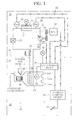
- FIG. 1 schematically shows a vehicle equipped with an automotive air-conditioning system which is an embodiment of the present invention.
- the automotive air-conditioning system can cool a passenger compartment 10 according to a temperature setting set as desired.
- the automotive air-conditioning system includes a refrigeration cycle system 12 for performing a refrigeration cycle.
- the refrigeration cycle system 12 has a circulation path 14 along which a refrigerant is forced to circulate as a working fluid.
- the circulation path 14 runs from an engine room 16 into an instrumentation space 18 through a partition 17.
- the instrumentation space 18 is defined by an instrument panel 20, in front of the passenger compartment 10.
- a compressor 100, 1 radiator (condenser) 24, a receiver ⁇ dryer 25 and an expansion valve 26 are arranged serially in the direction of flow of the refrigerant.
- an evaporator 28 In the section of the circulation path 14 running in the instrumentation space 18 is arranged an evaporator 28.
- the receiver ⁇ dryer 25 can be omitted.
- the compressor 100 is mechanically connected to an engine 29 and driven by power from the engine 29.
- the compressor 100 is, for example a variable displacement piston-type (reciprocating) compressor and includes a displacement control valve 200 as seen in FIG. 2 .
- the compressor 100 is a clutchless swashplate compressor, for example.
- the compressor 100 includes a cylinder block 101.
- the cylinder block 101 has a plurality of cylinder bores 101a.
- a front housing (crank case) 102 is joined at an end, and a rear housing (cylinder head) 104 is joined at the other end with a valve plate 103 interposed between.
- the cylinder block 101 and the front housing 102 define a crank chamber 105, and a drive shaft 106 extends axially across the interior of the crank chamber 105.
- the drive shaft 106 extends through an annular swashplate 107 arranged inside the crank chamber 105, and the swashplate 107 is hinged to a rotor 108, fixed on the drive shaft 106, by a joint 109.
- the swashplate 107 can therefore vary in inclination, while moving along the drive shaft 106.
- a coil spring 110 is mounted to push on the swashplate 107 toward a minimum inclination angle.
- a coil spring 111 is mounted on the drive shaft 106 to push on the swashplate 107 toward a maximum inclination angle.
- the drive shaft 106 extends through a boss 102a projecting outward from the front housing 102.
- a pulley 112 is provided as a power transmission device.
- the pulley 112 is rotatably attached to the boss 102a by means of a ball bearing 113. Between this pulley 112 and a pulley attached to the engine 29 is passed a belt 115 so that the engine 29 serves as an external drive source.
- a shaft sealing device 116 is provided inside the boss 102a to seal the front housing 102.
- the drive shaft 106 is rotatably supported by bearings 117, 118, 119 and 120 in the radial and thrust directions. Power is transmitted from the engine 29 to the pulley 112, so that the drive shaft 116 can rotate with the pulley 112.
- Each piston 130 has an integrally-formed tail portion projecting into the crank chamber 105.
- the tail portion has a recess 130a, in which a pair of shoes 132 is arranged.
- the shoes 132 are in sliding contact with the periphery of the swashplate 107 on both sides thereof.
- the shoes 132 enable the piston 130 and the swashplate 107 to move in conjunction with each other so that rotation of the drive shaft 106 is converted into reciprocating motion of the piston 130 within its own cylinder bore 101a.
- the rear housing 104 defines a suction chamber 140 and a discharge chamber 142.
- the suction chamber 140 is connected to each cylinder bore 101a by a suction hole 103a in the valve plate 103.
- the discharge chamber 142 is connected to each cylinder bore 101a by a discharge hole 103b in the valve plate 103.
- the suction hole 103a and the discharge hole 103b are opened and closed by a suction valve and a discharge valve, not shown, respectively.
- a muffler 150 Outside the cylinder block 101 is provided a muffler 150.
- the cylinder block 101 has an integrally-formed muffler base 101b, to which a muffler casing 152 is joined with a sealing member, not shown, interposed between.
- the muffler casing 152 and the muffler base 101b define a muffler space 154.
- the muffler space 154 is connected to the discharge chamber 142 by a discharge passage 156 which extends in the wall of the rear housing 104, then through the valve plate 103 and then through the wall of the muffler base 101b.
- the muffler casing 152 has a discharge port 152a, and a check valve 170 is provided in the muffler space 154 to block a flow between the discharge passage 156 and the discharge port 152a.
- the check valve 170 opens or closes depending on a pressure difference between the discharge passage 156 and the muffler space 154. More specifically, the check valve closes when the pressure difference becomes smaller than a predetermined value, and opens when the pressure difference becomes greater than the predetermined value.
- the discharge chamber 142 is connected to the outgoing side of the circulation path 14 by the discharge passage 156, the muffler space 154 and the discharge port 152a, where the check valve 170 allows or blocks a flow from the discharge chamber 142 to the muffler space 154.
- the suction chamber 140 is connected to the incoming side of the circulation path 14 by a suction port 104a in the rear housing 104.
- a displacement control valve 200 In the rear housing 104 is arranged a displacement control valve (electromagnetic control valve) 200.
- the displacement control valve 200 is provided in a gas supply passage 160.
- the gas supply passage 160 extends in the wall of the rear housing 104 and through the valve plate 103 and the cylinder block 101, thereby connecting the discharge chamber 142 and the crank chamber 105.
- the suction chamber 140 is connected to the crank chamber 105 by a gas release passage 162.
- the gas release passage 162 consists of clearances between the drive shaft 106 and the respective bearings 119, 200, a space 164 and a fixed orifice 103c in the valve plate 103.
- the suction chamber 140 is connected to the displacement control valve 200 by a pressure sensing passage 166 extending in the wall of the rear housing 104, independently of the gas supply passage 160.
- the displacement control valve 200 consists of a valve unit and a solenoid unit.
- the valve unit has a cylindrical valve housing 202.
- the valve housing 202 has a valve hole 204 inside.
- the valve hole 204 extends in the axial direction of the valve housing 202, and connects to an outlet port 206 at a first end.
- the outlet port 206 radially extends through the valve housing 202, so that the valve hole 204 is connected to the crank chamber by the discharge port 206 and the downstream side of the gas supply passage 160.
- the valve housing 202 has a valve chamber 208 in an end portion adjacent to the solenoid unit.
- the valve hole 204 has an open end at the end wall of the valve chamber 208, and thus, connects to the valve chamber 208 at a second end opposite to the aforementioned first end.
- Inside the valve chamber 208 is arranged a columnar valve element 210.
- the valve element 210 can move inside the valve chamber 208 in the axial direction of the valve housing 202, and close the valve hole 204 by coming in contact with the end wall of the valve chamber 202, at a first end.
- the end wall of the valve chamber 202 thus functions as a valve seat.
- the valve housing 202 also has an inlet port 212. Also the inlet port 212 radially extends through the valve housing 202.
- the inlet port 202 is connected to the discharge chamber 142 by the upstream side of the gas supply passage 160.
- the inlet port 202 has an open end at the side wall of the valve chamber 208, so that the discharge chamber 142 and the crank chamber 105 are connected via the inlet port 212, the valve chamber 208, the valve hole 204 and the outlet port 206.
- the valve housing 202 also has a pressure sensing chamber 214 in an end portion remote from the solenoid unit, and a pressure sensing port 216 extending through a side wall of the pressure sensing chamber 214.
- the pressure sensing chamber 214 is connected to the suction chamber 140 by the pressure sensing port 216 and the pressure sensing passage 166.
- the valve housing 202 also has an axial hole 218 extending between the pressure sensing chamber 214 and the valve hole 204, coaxially with the valve hole 204.
- a pressure sensing rod 210 is joined integrally and coaxially with the valve element 210.
- the pressure sensing rod 220 extends inside the valve hole 204 and the axial hole 218 and projects into the pressure sensing chamber 214 at a first end side.
- the pressure sensing rod 220 has a large-diameter portion at the first end side, which is slidably in contact with the inner surface of the axial hole 218. Thus, gas flow between the pressure sensing chamber 214 and the valve hole 204 is prevented by the large-diameter portion of the pressure sensing rod 220.
- a cap 222 is press-fitted to provide an end wall of the pressure sensing chamber 214.
- the cap 222 is in the form of a bottomed stepped cylinder.
- a support member 224 is slidably fitted with its cylindrical portion received in the small-diameter portion of the cap 222, and a force-open spring 226 is set between the bottom of the cap 222 and the support member 224.
- a pressure sensing device 228 Inside the pressure sensing chamber 214 is arranged a pressure sensing device 228.
- the pressure sensing device 228 is fixed to the support member 226 at a first end.
- the pressure sensing device 228 is thus supported by the support member 224 fitted in the cap 222.
- the pressure sensing device 228 includes a bellows 230.
- the bellows 230 can extract and contract in the axial direction of the valve housing 202.
- the bellows 230 is hermetically sealed by caps 232, 234 at first and second, ends, respectively, so that the interior of the bellows 230 is kept evacuated (depressurized).
- Inside the bellows 230 is arranged a compression coil spring 236.
- the compression coil spring 236 pushes on the caps 232, 234 in the directions in which the bellows 230 expands increasing the distance between the caps 232, 234.
- the cap 234 constituting the pressure sensing device 228 is mounted on an adaptor 238, which can come in contact with the pressure sensing rod 220.
- a pressure decrease in the pressure sensing chamber 214 causes the pressure sensing device 228 to expand and push the pressure sensing rod 220, and thus, the valve element 10 so that the valve is opened.
- the amount by which the cap 222 is pressed into the valve housing 202 is determined so that the displacement control valve 200 will behave as desired.
- the solenoid unit has a cylindrical solenoid housing 240 coaxially joined to the valve housing 202. Inside the solenoid housing 240 is arranged a cylindrical stationary core 242 coaxially.
- the stationary core 242 has a first end portion fitted in the valve housing 202, which defines the valve chamber 208 and receives the valve element 210 allowing the sliding thereof.
- a bottomed sleeve 244 to extend from the middle downward beyond a second end of the stationary core opposite to the aforementioned first end.
- the movable core 248 is slidably fitted in the sleeve 244 to be able to reciprocate in the axial direction of the solenoid housing 240.
- a solenoid rod 250 Inside the stationary core 242 extends a solenoid rod 250.
- the solenoid rod 250 is in contact with the second end of the valve element 210 at a first end, and integrally fixed to the movable core 248 at a second end opposite to the first end.
- a movement of the movable core 248 leads to a valve closure movement of the valve element 210.
- a compression coil spring 252 Between the movable core 248 and the bottom of the sleeve 244 is arranged a compression coil spring 252, which always pushes on the movable core 248 and solenoid rod 250, and thus, the valve element 210 in the direction of the valve closure movement.
- the sleeve 244 is arranged a cylindrical coil 254 of wire wound on a bobbin 253 (solenoid coil).
- the coil 254 wound on the bobbin 253 is surrounded by an integrally-molded resin member 255.
- the solenoid housing 240, the stationary core 242 and the movable core 248 are each made of a magnetic material so that they constitute a magnetic circuit.
- the sleeve 244 is made of a stainless steel-based non-magnetic material.
- the stationary core 242 has a radial hole 256 at the base of the first end portion, and the valve housing 202 has a connection hole 258 connecting the radial hole 256 to the pressure sensing chamber 214.
- the stationary core 242 In the region of the middle to the second end portion, the stationary core 242 has an inside diameter greater than the outer diameter of the valve element 210 and of the solenoid rod 250, so that the core holding space 246 connects to the pressure sensing chamber 214 via a clearance produced in the region of the middle to the second end portion of the stationary core 242, the radial hole 256 and the connection hole 258.
- crank pressure Pc acts on the first end face of the valve element 210 as a force tending to open the valve
- suction pressure Ps acts on the second end face of the valve element 210 as a force tending to close the valve
- the solenoid 254 of the displacement control valve is electrically connected to an air-conditioning control device (A/C control device) 32 provided for controlling the automotive air-conditioning system.
- the air-conditioning control device 32 regulates the size of driving current I supplied to the solenoid 254, thereby regulating the displacement of the compressor 100.
- the air-conditioning control device 32 may comprise electric circuits such as ECUs (electronic control units), for example.
- the displacement control valve 200 When the displacement control valve 200 is used, the displacement is controlled by Ps control, or control of suction pressure Ps with which the compressor 100 sucks the refrigerant.
- Ps control or control of suction pressure Ps with which the compressor 100 sucks the refrigerant.
- differential pressure control namely control of difference (Pd-Ps differential pressure) between the pressure in the discharge chamber 142 of the compressor 100, or in other words, pressure with which the compressor 100 discharges the refrigerant (discharge pressure Pd) and the suction pressure Ps can be adopted.
- FIG. 4 shows relation between driving current I supplied to the displacement control valve 200 and suction pressure Ps.
- a setpoint Pss of the suction pressure Ps is set from a variety of information including a passenger compartment temperature setting set by a passenger, and driving current I of a size based on the setpoint Pss is supplied to the solenoid 254.
- the displacement control valve 200 is thus brought to a valve position causing the suction pressure Ps to approach the setpoint Pss, while the pressure sensing device 228 for sensing the suction pressure Ps expands depending on the suction pressures Ps, thereby finely regulating the valve position to compensate for fluctuations of the suction pressure Ps.
- a condenser fan 33 near the radiator 24 is arranged a condenser fan 33.
- the refrigerant passing through the radiator 24 is cooled by airflow from before the vehicle, caused by the vehicle travelling, and/or airflow from the condenser fan 33.
- the expansion valve 26 causes the refrigerant to expand by passing through it.
- the expansion valve 26 is, for example a thermosensing expansion valve, and the valve position thereof is regulated so that the refrigerant will be at a predetermined superheated temperature at the outlet of the evaporator 28.
- the evaporator 28 is arranged inside an air-conditioning unit housing 34. Inside the air-conditioning unit housing 34 are also arranged a blower fan 36 and a heater core (not shown). At an inlet of the air-conditioning unit housing 34 is arranged an inside/outside air switch damper 38 is arranged, and at an outlet of the air-conditioning unit housing 34 is arranged a vent switch damper (not shown).
- the refrigerant passing through the evaporator 28 evaporates by being heated by air from the blower fan 36.
- the air from the blower fan 36 is therefore cooled, or in other words, becomes cold air in the evaporator 28, which flows into and cools the passenger compartment 10.
- the automotive air-conditioning system has a group of sensors for obtaining a variety of information, including an outside air temperature sensor 42, an evaporator-outlet air temperature sensor 44, a radiator-inlet refrigerant pressure sensor 46 and a radiator-outlet refrigerant pressure sensor 48.
- the outside air temperature sensor 42, the evaporator-outlet air temperature sensor 44, the radiator-inlet refrigerant pressure sensor 46 and the radiator-outlet refrigerant pressure sensor 48 are each electrically connected to the air-conditioning control device 32.
- a vehicle control system which includes a vehicle control device (engine control device) 50.
- vehicle control device 50 may comprise electronic circuits such as ECUs.
- the vehicle control device 50 mainly controls the rotational speed Ne of the engine 29 on the basis of the passenger's input by operating an accelerator pedal 52 and other control means not shown, including a brake pedal and a shift lever, arranged in the passenger compartment 10.
- the vehicle control device 50 also detects the rotational speed Ne of the engine 29 by means of a rotational speed sensor, for example, and feeds detected values of the engine 29 rotational speed Ne.
- the air-conditioning control device 32 receives those detected values of the engine 29 rotational speed Ne.
- FIG. 5 shows transmission of signals among the solenoid 254 of the displacement control valve 200, the air-conditioning control device 32, the vehicle control device 50 and sensors.
- the air-conditioning control device 32 receives information including a passenger compartment 10 temperature setting, via an operation panel, and an outside temperature Ta and an evaporator-outlet air temperature Tc detected by the outside air temperature sensor 42 and the evaporator-outlet air temperature sensor 44, respectively. On the basis of the information received, the air-conditioning control device 32 sets a desired value of driving current I supplied to the solenoid 254 of the displacement control valve 200, and regulates the driving current I to approach the desired value. As a result, the displacement of the variable displacement compressor 100 is regulated to a predetermined value.
- the air-conditioning control device 32 also functions as a calculation means for calculating driving torque Tr on the variable displacement compressor 100. For this calculation, the air-conditioning control device 32 receives radiator-inlet refrigerant pressure Pin and radiator-outlet refrigerant pressure Pout, detected by the radiator-inlet refrigerant pressure sensor 46 and the radiator-outlet refrigerant pressure sensor 48, respectively, in addition to the engine 29 rotational speed Ne.
- the air-conditioning control device 32, the engine rotational speed detection means, the radiator-inlet refrigerant pressure sensor 46 and the radiator-outlet refrigerant pressure sensor 48 constitute a compressor 100 driving torque calculation device.
- the air-conditioning control device 32 includes a circuit for calculating driving torque Tr on the compressor 100 (driving torque calculation circuit) 300.
- the driving torque calculation circuit 300 includes a compressor rotational speed calculation section 301, a refrigerant flow rate calculation section 302, a maximum refrigerant flow rate calculation section 304, a displacement determination section 305, a suction pressure calculation section 306, and an enthalpy difference calculation section 308 and a machine efficiency calculation section 310.
- FIG. 6 is a flow chart showing an example of a program for calculating driving torque Tr on the compressor 100, which the driving toque calculation circuit 300 executes at predetermined intervals.
- a radiator-inlet refrigerant pressure Pin a radiator-outlet refrigerant pressure Pout, an engine rotational speed Ne and a driving current I supplied to the displacement control valve 200 are read (S10).
- a compressor 100 rotational speed Nc is calculated on the basis of the engine rotational speed Ne (S11).
- a coefficient in the function F 0 can be determined in advance from a pulley ratio between the engine 29 and the compressor 100.
- a maximum refrigerant flow rate Grmax is calculated on the basis of the radiator-inlet refrigerant pressure Pin, the radiator-outlet refrigerant pressure Pout, the compressor rotational speed Nc and the driving current I supplied to the displacement control valve 200 (S12).
- the maximum refrigerant flow rate Grmax is a flow rate of the refrigerant circulating along the circulation path 14 on the assumption that the compressor 100 is working with a maximum displacement.
- the function F 1 can be determined in advance by a bench test of the automotive air-conditioning system not yet installed on a vehicle. Coefficients in the function F 1 can thus be determined independently from the vehicle design.
- a refrigerant flow rate Gr is calculated on the basis of the radiator-inlet refrigerant pressure Pin and the radiator-outlet refrigerant pressure Pout.
- the radiation performance of the radiator 14 differs depending on the vehicle design, including the shape of a radiator grill and the arrangement of the radiator 14 on the vehicle, and thus, coefficients in the function F 2 are not fixed.
- the coefficients in the function F 2 are therefore determined on the basis of measured values of the variables, i.e., the radiator-inlet refrigerant pressure Pin, the radiator-outlet refrigerant pressure Pout and the refrigerant flow rate Gr obtained by operating the automotive air-conditioning system installed on a vehicle, under a small number, for example 10 or so of different sets of conditions.
- the driving torque calculation circuit 300 determines whether the compressor 100 is working with a maximum displacement by comparing the maximum refrigerant flow rate Grmax and the refrigerant flow rate Gr, calculated as described above (S14). If the refrigerant flow rate Gr is greater than or equal to the maximum refrigerant flow rate Grmax (Gr ⁇ Grmax), it is determined that the compressor 100 is working with the maximum displacement (Yes). If the refrigerant flow rate Gr is less than the maximum refrigerant flow rate Grmax (Gr ⁇ Grmax), it is determined that the compressor 100 is not working with the maximum displacement (No).
- a suction pressure Ps, or pressure with which the compressor 100 is sucking the refrigerant is calculated on the basis of the driving current I supplied to the displacement control valve 200 (S16).
- the function F 3 which is exemplified by FIG. 4 , can be determined in advance by a bench test of the automotive air-conditioning system not yet installed on a vehicle. A coefficient in the function F 3 can thus be determined independently from the vehicle design.
- an enthalpy difference ⁇ h is calculated on the basis of the radiator-inlet refrigerant pressure Pin, the compressor rotational speed Nc, the refrigerant flow rate Gr and the suction pressure Ps calculated at step S14 (S18).
- the enthalpy difference ⁇ h is a difference (hd-hs) between the enthalpy hd of the refrigerant discharged from the compressor 100 and the enthalpy of the refrigerant sucked into the compressor 100.
- the function F 4 can be determined in advance by a bench test of the automotive air-conditioning system not yet installed on a vehicle. Coefficients in the function F 4 can thus be determined independently from the vehicle design.
- a machine efficiency ⁇ m of the compressor 100 is calculated on the basis of the radiator-inlet refrigerant pressure Pin, the compressor rotational speed Nc and the suction pressure calculated at step S14.
- the function F 5 can be determined in advance by a bench test of the automotive air-conditioning system not yet installed on a vehicle. Coefficients in the function F 5 can thus be determined independently from the vehicle design.
- a driving torque Tr on the compressor 100 is calculated (S20).
- the function F 7 can be determined in advance by a bench test of the automotive air-conditioning system not yet installed on a vehicle. Coefficients in the function F 7 can thus be determined independently from the vehicle design.
- an enthalpy difference ⁇ h is calculated on the basis of the radiator-inlet refrigerant pressure Pin, the compressor rotational speed Nc, the refrigerant flow rate Gr and the suction pressure Ps calculated at step S22 (S24).
- the function F 8 can be determined in advance by a bench test of the automotive air-conditioning system not yet installed on a vehicle. Coefficients in the function F 8 can thus be determined independently from the vehicle design.
- a machine efficiency ⁇ m of the compressor 100 is calculated on the basis of the radiator-inlet refrigerant pressure Pin, the compressor rotational speed Nc and the suction pressure Ps calculated at step S22.
- the function F 9 can be determined in advance by a bench test of the automotive air-conditioning system not yet installed on a vehicle. Coefficients in the function F 9 can thus be determined independently from the vehicle design.
- a driving torque Tr is calculated in the same way as in the processing route including steps S16 and S18, except that the enthalpy difference ⁇ h and machine efficiency ⁇ m calculated at step S24 are used. Then, at step S22, the calculated value of driving torque Tr is fed.
- the driving torque calculation circuit 300 calculates the driving torque Tr on the variable displacement compressor 100 on the basis of the pressures Pin, Pout of the refrigerant at the inlet and outlet of the radiator 24, the rotational speed Nc of the variable displacement compressor 100 and the refrigerant suction pressure Ps, without need for map data. This saves the trouble of preparing map data by operating the automotive air-conditioning system installed on a vehicle under a great number, perhaps 1000 or so of different sets of conditions and taking measurements of the driving torque and a variety of parameters.
- the driving torque calculation device is therefore easy to apply to vehicles of different designs, and contributes to reduction in price of automotive air-conditioning systems and of vehicles.
- the driving torque Tr is accurately calculated by the driving torque calculation circuit 300 using the predetermined expression.
- the flow rate of the refrigerant circulating along the circulation path 14 is accurately calculated by the flow rate calculation section 302, which leads to accurate calculation of the driving torque Tr.
- the enthalpy difference ⁇ h is accurately calculated by the enthalpy difference calculation section 308, which leads to accurate calculation of the driving torque Tr.
- the machine efficiency is accurately calculated by the machine efficiency calculation section 310, which leads to accurate calculation of the driving torque Tr.
- the suction pressure Ps is accurately calculated by the suction pressure calculation section 306, which leads to accurate calculation of the driving torque Tr.
- the suction pressure Ps at the time that the variable displacement compressor 100 is working with the maximum displacement is accurately calculated by the suction pressure calculation section 306, which leads to accurate calculation of the driving torque Tr.
- engine control is optimized by controlling the engine 29 using the value of variable displacement compressor 100 driving torque Tr calculated by the driving torque calculation device. This leads to stable operation of the engine 29 and of the automotive air-conditioning system, and thus, increase in vehicle drivability, fuel efficiency, and passenger compartment comfort.
- the suction pressure Ps, the enthalpy difference ⁇ h and the machine efficiency ⁇ m are calculated in different ways depending on the result of determination at step S14, namely whether the compressor 100 is working with the maximum displacement.
- steps S14, S22 and S24 may be omitted.
- the compressor rotational speed Nc is calculated on the basis of a signal indicative of the engine rotational speed Ne transmitted from the vehicle control device 50.
- the means for calculating or detecting the compressor rotational speed Nc is however not restricted to this; the compressor rotational speed Nc may be detected directly by a rotational speed sensor.
- the displacement is controlled by suction pressure control.
- the present invention is however also applicable to the variable displacement compressor in which the displacement is controlled by Pd-Ps differential pressure control.
- suction pressure Ps is calculated from driving current I correlating with Pd-Ps differential pressure, and radiator-inlet refrigerant pressure Pin correlating with discharge pressure Pd.
- the discharge pressure Pd differs from the radiator-inlet refrigerant pressure Pin.
- the difference can however be appropriately compensated for.
- a discharge pressure sensor fitted to the compressor 100 to be used as a sensor for detecting the radiator-inlet refrigerant pressure sensor.
- the driving torque Tr is calculated by calculating the values of functions F 0 , F 1 , F 2 , F 3 , F 4 , F 5 and F 6 or of functions F 0 , F 1 , F 2 , F 7 , F 8 , F 9 and F 6 , serially, where some function is involved in another function as a variable. These functions may, of course, be combined appropriately so that the driving torque Tr will be calculated using the resulting combined functions.
- the driving torque Tr is calculated by detecting the radiator-inlet refrigerant pressure Pin, the radiator-outlet refrigerant pressure Pout, the driving current I and the compressor rotational speed Ne directly or indirectly through calculation, and preferably using the function F 6 .
Abstract
Description
- This invention relates to a variable displacement compressor driving torque calculation device and an automotive air-conditioning system.
- An automotive air-conditioning system includes a system for performing a refrigeration cycle (refrigeration cycle system). The refrigeration cycle system has a circulation path along which a refrigerant circulates as a working fluid. In the circulation path, a compressor, a radiator (condenser), an expander (expansion valve) and an evaporator are arranged serially.
- To the compressor, power (driving torque) is transmitted from an engine by a belt. Thus, from a viewpoint of control over the vehicle engine, the compressor is a load, and particularly at high outside air temperature, affects vehicle drivability including acceleration performance, and fuel efficiency.
- From a viewpoint of control over the automotive air-conditioning system, variations in engine rotational speed lead to variations in compressor rotational speed, and thus, destabilize the refrigeration cycle and cause variations in passenger compartment temperature.
- To deal with this, compressor driving torque is calculated for use in engine control. For example, a variable displacement compressor driving torque calculation device disclosed in patent document 1 has a plurality of compressor driving torque maps prepared for differing compressor discharge-side pressures. The calculation device chooses an optimal compressor driving torque map for a current compressor discharge-side pressure, identifies, in the chosen map, a proportional characteristic at a current rotational speed of the driven compressor, and calculates a compressor driving torque at a current refrigerant flow rate from the identified proportional characteristic.
- There are various types of variable displacement compressors, among which, for example an externally-controlled piston-type variable displacement compressor is widely used.
- The variable displacement compressor of this type has a displacement control valve, and driving current supplied to the displacement control valve is controlled by an external control device. The control device regulates the driving current so that either suction pressure in the refrigeration cycle system or a pressure difference between two predetermined locations (pressure difference between discharge pressure and suction pressure, for example) will approach a desired value. Regulation of the driving current causes a change in valve position of the displacement control valve, which causes an increase or decrease in pressure in a crank chamber of the compressor, and thus, a change in displacement of the compressor.
-
- Patent document 1: Japanese Patent Application Laid-open No.
2003-278663 - In application of the variable displacement compressor driving torque calculation device disclosed in patent document 1 to vehicles, it is necessary to prepare a plurality of sets of compressor driving torque maps, since radiation performance of the radiator varies depending on the design of vehicles, including the shape of a radiator grill. Thus, each time a new vehicle is developed, it is necessary to operate the automotive air-conditioning system on the actual vehicle under 100 or more of different sets of conditions and take measurements of the driving torque and a variety of parameters.
- Such preparation of compressor driving torque maps is not only troublesome but also requires a lot of man-hours and costs, and thus, hinders reduction in cost of the automotive air-conditioning system and of the vehicle.
- The present invention has been made in consideration of the above problem. An object of the present invention is to provide a variable displacement compressor driving torque calculation device easily adaptable to vehicle designs, and thus, highly versatile, and an automotive air-conditioning system equipped with this device.
- In order to achieve the above object, the present invention provides, as one embodiment, a variable displacement compressor driving toque calculation device for calculating driving torque on a variable displacement compressor, for use in an automotive refrigeration cycle system including the variable displacement compressor, a radiator, an expansion valve and an evaporator, serially arranged in a circulation path in a vehicle along which a refrigerant circulates, and also including a displacement control valve for regulating displacement of the variable displacement compressor and a displacement control means for regulating driving current supplied to the displacement control valve, thereby regulating valve position of the variable displacement valve to control the displacement of the variable displacement compressor, characterized by comprising a radiator-inlet refrigerant pressure sensor for detecting pressure of the refrigerant at an inlet of the radiator, a radiator-outlet refrigerant pressure sensor for detecting pressure of the refrigerant at an outlet of the radiator, a rotational speed detection means for detecting rotational speed of the variable displacement compressor, a suction pressure detection means for detecting suction pressure with which the variable displacement compressor sucks the refrigerant, and a calculation means for calculating the driving torque on the variable displacement compressor on the basis of the pressures of the refrigerant at the inlet and the outlet of the radiator, the rotational speed of the variable displacement compressor and the suction pressure (Claim 1).
- Desirably, the calculation means calculates the driving torque by an expression:

(where Tr is the driving torque on the variable displacement compressor, Nc the rotational speed of the variable displacement compressor, hd enthalpy of the refrigerant discharged from the variable displacement compressor, hs enthalpy of the refrigerant sucked into the variable displacement compressor, ηm mechanical efficiency of the variable displacement compressor and Gr flow rate of the refrigerant circulating along the circulation path) (claim 2). - Desirably, the calculation means includes a refrigerant flow rate calculation section for calculating the flow rate of the refrigerant circulating along the circulation path on the basis of the pressures of the refrigerant at the inlet and the outlet of the radiator (claim 3).
- Desirably, the calculation means includes an enthalpy difference calculation section for calculating a difference between the enthalpy of the refrigerant discharged from the variable displacement compressor and the enthalpy of the refrigerant sucked into the variable displacement compressor, on the basis of the pressure of the refrigerant at the inlet of the radiator, the suction pressure, the flow rate of the refrigerant and the rotational speed of the variable displacement compressor (claim 4).
- Desirably, the calculation means includes a machine efficiency calculation section for calculating the machine efficiency on the basis of the pressure of the refrigerant at the inlet of the radiator, the suction pressure and the rotational speed of the variable displacement compressor (claim 5).
- Desirably, the calculation means includes a displacement determination means for determining whether the variable displacement compressor is working with a maximum displacement, wherein when the displacement determination means determines that the variable displacement compressor is working with the maximum displacement, the machine efficiency calculation section calculates the machine efficiency on the basis of the pressure of the refrigerant at the inlet of the radiator, the suction pressure, the rotational speed of the variable displacement compressor and the flow rate of the refrigerant circulating along the circulation path (claim 6).
- Desirably, the displacement control means regulates the driving current so that the suction pressure will approach a desired value, wherein the calculation means includes a suction pressure calculation means for calculating the suction pressure on the basis of the driving current (claim 7).
- Desirably, the calculation means includes a displacement determination means for determining whether the variable displacement compressor is working with a maximum displacement, wherein when the displacement determination means determines that the variable displacement compressor is working with the maximum displacement, the suction pressure calculation section calculates the suction pressure on the basis of not the driving current but the pressure of the refrigerant at the inlet of the radiator, the rotational speed of the variable displacement compressor and the flow rate of the refrigerant circulating along the circulation path (claim 8).
- The present invention further provides, as one embodiment, an automotive air-conditioning system including the variable displacement compressor driving torque calculation device described above (claim 9).
- In the variable displacement compressor driving torque calculation device according to the present invention recited in claim 1, the calculation means calculates the driving torque on the variable displacement compressor on the basis of the pressures of the refrigerant at the inlet and the outlet of the radiator, the rotational speed of the variable displacement compressor and the suction pressure, without need for map data. This saves the trouble of preparing map data by operating an automotive air-conditioning system installed on a vehicle under a great number of different sets of conditions and taking measurements of the driving torque and a variety of parameters. This driving torque calculation device is therefore easy to apply to vehicles of different designs, and contributes to reduction in price of automotive air-conditioning systems and of vehicles.
- In the variable displacement compressor driving torque calculation device recited in claim 2, the driving torque is accurately calculated by the calculation means using the predetermined expression.
- In the variable displacement compressor driving torque calculation device recited in claim 3, the flow rate of the refrigerant circulating along the circulation path is accurately calculated by the refrigerant flow rate calculation section, which leads to accurate calculation of the driving torque.
- In the variable displacement compressor driving torque calculation device recited in claim 4, the difference between the enthalpy of the refrigerant discharged from the variable displacement compressor and the enthalpy of the refrigerant sucked into the variable displacement compressor is accurately calculated by the enthalpy difference calculation section, which leads to accurate calculation of the driving torque.
- In the variable displacement compressor driving torque calculation device recited in claim 5, the machine efficiency is accurately calculated by the machine efficiency calculation section, which leads to accurate calculation of the driving torque.
- In the variable displacement compressor driving torque calculation device recited in claim 6, the machine efficiency at the time that the variable displacement compressor is working with the maximum displacement is accurately calculated by the machine efficiency calculation section, which leads to accurate calculation of the driving torque.
- In the variable displacement compressor driving torque calculation device recited in claim 7, the suction pressure is accurately calculated by the suction pressure calculation section, which leads to accurate calculation of the driving torque.
- In the variable displacement compressor driving torque calculation device recited in claim 8, the suction pressure at the time that the variable displacement compressor is working with the maximum displacement is accurately calculated by the suction pressure calculation section, which leads to accurate calculation of the driving torque.
- In a vehicle equipped with the automotive air-conditioning system recited in claim 9 applied, engine control is optimized by controlling the engine using the value of variable displacement compressor driving torque calculated by the variable displacement compressor driving torque calculation device. This leads to stable operation of the engine and of the automotive air-conditioning system, and thus, increase in vehicle drivability, fuel efficiency, and passenger compartment comfort.
-
-
FIG. 1 is a diagram schematically showing the configuration of a vehicle equipped with an automotive air-conditioning system which is an embodiment of the present invention, -
FIG. 2 is a diagram schematically showing the configuration of a refrigeration cycle system included in the automotive air-conditioning system shown inFIG. 1 , where a compressor is shown in vertical cross-section, -
FIG. 3 is a diagram showing how a displacement control valve, provided for the compressor shown inFIG. 2 , is connected, where the displacement control valve is shown in cross-section, -
FIG. 4 is a graph showing relation between driving current supplied to the displacement control valve and suction pressure, observed in the automotive air-conditioning system shown inFIG. 1 , -
FIG. 5 is a diagram showing signal transmission in the vehicle shown inFIG. 1 , and -
FIG. 6 is a flow chart showing a program executed by a driving torque calculation device included in the automotive air-conditioning system shown inFIG. 1 . -
FIG. 1 schematically shows a vehicle equipped with an automotive air-conditioning system which is an embodiment of the present invention. The automotive air-conditioning system can cool apassenger compartment 10 according to a temperature setting set as desired. - The automotive air-conditioning system includes a
refrigeration cycle system 12 for performing a refrigeration cycle. Therefrigeration cycle system 12 has acirculation path 14 along which a refrigerant is forced to circulate as a working fluid. - The
circulation path 14 runs from anengine room 16 into aninstrumentation space 18 through apartition 17. Theinstrumentation space 18 is defined by aninstrument panel 20, in front of thepassenger compartment 10. In the section of thecirculation path 14 running in theengine room 16, acompressor 100, 1 radiator (condenser) 24, a receiver·dryer 25 and anexpansion valve 26 are arranged serially in the direction of flow of the refrigerant. In the section of thecirculation path 14 running in theinstrumentation space 18 is arranged anevaporator 28. The receiver·dryer 25 can be omitted. - The
compressor 100 is mechanically connected to anengine 29 and driven by power from theengine 29. Thecompressor 100 is, for example a variable displacement piston-type (reciprocating) compressor and includes adisplacement control valve 200 as seen inFIG. 2 . - More specifically, the
compressor 100 is a clutchless swashplate compressor, for example. Thecompressor 100 includes acylinder block 101. Thecylinder block 101 has a plurality of cylinder bores 101a. To thecylinder block 101, a front housing (crank case) 102 is joined at an end, and a rear housing (cylinder head) 104 is joined at the other end with avalve plate 103 interposed between. - The
cylinder block 101 and thefront housing 102 define a crankchamber 105, and adrive shaft 106 extends axially across the interior of thecrank chamber 105. Thedrive shaft 106 extends through anannular swashplate 107 arranged inside thecrank chamber 105, and theswashplate 107 is hinged to arotor 108, fixed on thedrive shaft 106, by a joint 109. Theswashplate 107 can therefore vary in inclination, while moving along thedrive shaft 106. - On the
drive shaft 106, between therotor 108 and theswashplate 107, acoil spring 110 is mounted to push on theswashplate 107 toward a minimum inclination angle. On the other side of theswashplate 107, namely between the swashplate 107 and thecylinder block 101, acoil spring 111 is mounted on thedrive shaft 106 to push on theswashplate 107 toward a maximum inclination angle. - The
drive shaft 106 extends through aboss 102a projecting outward from thefront housing 102. At the outer end of thedrive shaft 106, apulley 112 is provided as a power transmission device. Thepulley 112 is rotatably attached to theboss 102a by means of aball bearing 113. Between thispulley 112 and a pulley attached to theengine 29 is passed abelt 115 so that theengine 29 serves as an external drive source. - A
shaft sealing device 116 is provided inside theboss 102a to seal thefront housing 102. Thedrive shaft 106 is rotatably supported bybearings engine 29 to thepulley 112, so that thedrive shaft 116 can rotate with thepulley 112. - Within the
respective cylinder bores 101a are fittedpistons 130. Eachpiston 130 has an integrally-formed tail portion projecting into thecrank chamber 105. The tail portion has arecess 130a, in which a pair ofshoes 132 is arranged. Theshoes 132 are in sliding contact with the periphery of theswashplate 107 on both sides thereof. Thus, theshoes 132 enable thepiston 130 and theswashplate 107 to move in conjunction with each other so that rotation of thedrive shaft 106 is converted into reciprocating motion of thepiston 130 within itsown cylinder bore 101a. - The
rear housing 104 defines asuction chamber 140 and adischarge chamber 142. Thesuction chamber 140 is connected to eachcylinder bore 101a by asuction hole 103a in thevalve plate 103. Thedischarge chamber 142 is connected to eachcylinder bore 101a by adischarge hole 103b in thevalve plate 103. Thesuction hole 103a and thedischarge hole 103b are opened and closed by a suction valve and a discharge valve, not shown, respectively. - Outside the
cylinder block 101 is provided amuffler 150. Thecylinder block 101 has an integrally-formedmuffler base 101b, to which amuffler casing 152 is joined with a sealing member, not shown, interposed between. Themuffler casing 152 and themuffler base 101b define amuffler space 154. Themuffler space 154 is connected to thedischarge chamber 142 by adischarge passage 156 which extends in the wall of therear housing 104, then through thevalve plate 103 and then through the wall of themuffler base 101b. - The
muffler casing 152 has adischarge port 152a, and acheck valve 170 is provided in themuffler space 154 to block a flow between thedischarge passage 156 and thedischarge port 152a. Thecheck valve 170 opens or closes depending on a pressure difference between thedischarge passage 156 and themuffler space 154. More specifically, the check valve closes when the pressure difference becomes smaller than a predetermined value, and opens when the pressure difference becomes greater than the predetermined value. - Thus, the
discharge chamber 142 is connected to the outgoing side of thecirculation path 14 by thedischarge passage 156, themuffler space 154 and thedischarge port 152a, where thecheck valve 170 allows or blocks a flow from thedischarge chamber 142 to themuffler space 154. Thesuction chamber 140 is connected to the incoming side of thecirculation path 14 by asuction port 104a in therear housing 104. - In the
rear housing 104 is arranged a displacement control valve (electromagnetic control valve) 200. Thedisplacement control valve 200 is provided in agas supply passage 160. Thegas supply passage 160 extends in the wall of therear housing 104 and through thevalve plate 103 and thecylinder block 101, thereby connecting thedischarge chamber 142 and thecrank chamber 105. - The
suction chamber 140 is connected to the crankchamber 105 by agas release passage 162. Thegas release passage 162 consists of clearances between thedrive shaft 106 and therespective bearings space 164 and afixed orifice 103c in thevalve plate 103. - The
suction chamber 140 is connected to thedisplacement control valve 200 by apressure sensing passage 166 extending in the wall of therear housing 104, independently of thegas supply passage 160. - As shown in
FIG. 3 , thedisplacement control valve 200 consists of a valve unit and a solenoid unit. The valve unit has acylindrical valve housing 202. Thevalve housing 202 has avalve hole 204 inside. Thevalve hole 204 extends in the axial direction of thevalve housing 202, and connects to anoutlet port 206 at a first end. Theoutlet port 206 radially extends through thevalve housing 202, so that thevalve hole 204 is connected to the crank chamber by thedischarge port 206 and the downstream side of thegas supply passage 160. - The
valve housing 202 has avalve chamber 208 in an end portion adjacent to the solenoid unit. Thevalve hole 204 has an open end at the end wall of thevalve chamber 208, and thus, connects to thevalve chamber 208 at a second end opposite to the aforementioned first end. Inside thevalve chamber 208 is arranged acolumnar valve element 210. Thevalve element 210 can move inside thevalve chamber 208 in the axial direction of thevalve housing 202, and close thevalve hole 204 by coming in contact with the end wall of thevalve chamber 202, at a first end. The end wall of thevalve chamber 202 thus functions as a valve seat. - The
valve housing 202 also has aninlet port 212. Also theinlet port 212 radially extends through thevalve housing 202. Theinlet port 202 is connected to thedischarge chamber 142 by the upstream side of thegas supply passage 160. Theinlet port 202 has an open end at the side wall of thevalve chamber 208, so that thedischarge chamber 142 and thecrank chamber 105 are connected via theinlet port 212, thevalve chamber 208, thevalve hole 204 and theoutlet port 206. - The
valve housing 202 also has apressure sensing chamber 214 in an end portion remote from the solenoid unit, and apressure sensing port 216 extending through a side wall of thepressure sensing chamber 214. Thepressure sensing chamber 214 is connected to thesuction chamber 140 by thepressure sensing port 216 and thepressure sensing passage 166. Thevalve housing 202 also has anaxial hole 218 extending between thepressure sensing chamber 214 and thevalve hole 204, coaxially with thevalve hole 204. - At a second end of the
valve element 210 opposite to the aforementioned first end, apressure sensing rod 210 is joined integrally and coaxially with thevalve element 210. Thepressure sensing rod 220 extends inside thevalve hole 204 and theaxial hole 218 and projects into thepressure sensing chamber 214 at a first end side. Thepressure sensing rod 220 has a large-diameter portion at the first end side, which is slidably in contact with the inner surface of theaxial hole 218. Thus, gas flow between thepressure sensing chamber 214 and thevalve hole 204 is prevented by the large-diameter portion of thepressure sensing rod 220. - In an end portion of the
valve housing 202, acap 222 is press-fitted to provide an end wall of thepressure sensing chamber 214. Thecap 222 is in the form of a bottomed stepped cylinder. In thecap 222, asupport member 224 is slidably fitted with its cylindrical portion received in the small-diameter portion of thecap 222, and a force-open spring 226 is set between the bottom of thecap 222 and thesupport member 224. - Inside the
pressure sensing chamber 214 is arranged apressure sensing device 228. Thepressure sensing device 228 is fixed to thesupport member 226 at a first end. Thepressure sensing device 228 is thus supported by thesupport member 224 fitted in thecap 222. - The
pressure sensing device 228 includes a bellows 230. Thebellows 230 can extract and contract in the axial direction of thevalve housing 202. The bellows 230 is hermetically sealed bycaps bellows 230 is kept evacuated (depressurized). Inside thebellows 230 is arranged acompression coil spring 236. Thecompression coil spring 236 pushes on thecaps bellows 230 expands increasing the distance between thecaps - The
cap 234 constituting thepressure sensing device 228 is mounted on anadaptor 238, which can come in contact with thepressure sensing rod 220. A pressure decrease in thepressure sensing chamber 214 causes thepressure sensing device 228 to expand and push thepressure sensing rod 220, and thus, thevalve element 10 so that the valve is opened. - The amount by which the
cap 222 is pressed into thevalve housing 202 is determined so that thedisplacement control valve 200 will behave as desired. - The solenoid unit has a
cylindrical solenoid housing 240 coaxially joined to thevalve housing 202. Inside thesolenoid housing 240 is arranged a cylindricalstationary core 242 coaxially. Thestationary core 242 has a first end portion fitted in thevalve housing 202, which defines thevalve chamber 208 and receives thevalve element 210 allowing the sliding thereof. - On the
stationary core 242 is fitted a bottomedsleeve 244 to extend from the middle downward beyond a second end of the stationary core opposite to the aforementioned first end. Between the bottom of thesleeve 244 and the second end of thestationary core 242 is defined acore holding space 246, in which amovable core 248 is arranged. Themovable core 248 is slidably fitted in thesleeve 244 to be able to reciprocate in the axial direction of thesolenoid housing 240. - Inside the
stationary core 242 extends asolenoid rod 250. Thesolenoid rod 250 is in contact with the second end of thevalve element 210 at a first end, and integrally fixed to themovable core 248 at a second end opposite to the first end. Thus, a movement of themovable core 248 leads to a valve closure movement of thevalve element 210. Between themovable core 248 and the bottom of thesleeve 244 is arranged acompression coil spring 252, which always pushes on themovable core 248 andsolenoid rod 250, and thus, thevalve element 210 in the direction of the valve closure movement. - Around the
sleeve 244 is arranged acylindrical coil 254 of wire wound on a bobbin 253 (solenoid coil). Thecoil 254 wound on thebobbin 253 is surrounded by an integrally-moldedresin member 255. Thesolenoid housing 240, thestationary core 242 and themovable core 248 are each made of a magnetic material so that they constitute a magnetic circuit. Thesleeve 244 is made of a stainless steel-based non-magnetic material. - The
stationary core 242 has aradial hole 256 at the base of the first end portion, and thevalve housing 202 has aconnection hole 258 connecting theradial hole 256 to thepressure sensing chamber 214. In the region of the middle to the second end portion, thestationary core 242 has an inside diameter greater than the outer diameter of thevalve element 210 and of thesolenoid rod 250, so that thecore holding space 246 connects to thepressure sensing chamber 214 via a clearance produced in the region of the middle to the second end portion of thestationary core 242, theradial hole 256 and theconnection hole 258. - Accordingly, the pressure in the crank chamber 105 (crank pressure Pc) acts on the first end face of the
valve element 210 as a force tending to open the valve, and the pressure in the suction chamber 140 (suction pressure Ps) acts on the second end face of thevalve element 210 as a force tending to close the valve. - The
solenoid 254 of the displacement control valve is electrically connected to an air-conditioning control device (A/C control device) 32 provided for controlling the automotive air-conditioning system. The air-conditioning control device 32 regulates the size of driving current I supplied to thesolenoid 254, thereby regulating the displacement of thecompressor 100. The air-conditioning control device 32 may comprise electric circuits such as ECUs (electronic control units), for example. - When the
displacement control valve 200 is used, the displacement is controlled by Ps control, or control of suction pressure Ps with which thecompressor 100 sucks the refrigerant. Depending on the type of the displacement control valve, differential pressure control, namely control of difference (Pd-Ps differential pressure) between the pressure in thedischarge chamber 142 of thecompressor 100, or in other words, pressure with which thecompressor 100 discharges the refrigerant (discharge pressure Pd) and the suction pressure Ps can be adopted. -
FIG. 4 shows relation between driving current I supplied to thedisplacement control valve 200 and suction pressure Ps. In Ps control, a setpoint Pss of the suction pressure Ps is set from a variety of information including a passenger compartment temperature setting set by a passenger, and driving current I of a size based on the setpoint Pss is supplied to thesolenoid 254. Thedisplacement control valve 200 is thus brought to a valve position causing the suction pressure Ps to approach the setpoint Pss, while thepressure sensing device 228 for sensing the suction pressure Ps expands depending on the suction pressures Ps, thereby finely regulating the valve position to compensate for fluctuations of the suction pressure Ps. - Referring back to
FIG. 1 , near theradiator 24 is arranged acondenser fan 33. The refrigerant passing through theradiator 24 is cooled by airflow from before the vehicle, caused by the vehicle travelling, and/or airflow from thecondenser fan 33. - The
expansion valve 26 causes the refrigerant to expand by passing through it. Theexpansion valve 26 is, for example a thermosensing expansion valve, and the valve position thereof is regulated so that the refrigerant will be at a predetermined superheated temperature at the outlet of theevaporator 28. - The
evaporator 28 is arranged inside an air-conditioning unit housing 34. Inside the air-conditioning unit housing 34 are also arranged ablower fan 36 and a heater core (not shown). At an inlet of the air-conditioning unit housing 34 is arranged an inside/outsideair switch damper 38 is arranged, and at an outlet of the air-conditioning unit housing 34 is arranged a vent switch damper (not shown). - The refrigerant passing through the
evaporator 28 evaporates by being heated by air from theblower fan 36. The air from theblower fan 36 is therefore cooled, or in other words, becomes cold air in theevaporator 28, which flows into and cools thepassenger compartment 10. - The automotive air-conditioning system has a group of sensors for obtaining a variety of information, including an outside
air temperature sensor 42, an evaporator-outletair temperature sensor 44, a radiator-inletrefrigerant pressure sensor 46 and a radiator-outletrefrigerant pressure sensor 48. The outsideair temperature sensor 42, the evaporator-outletair temperature sensor 44, the radiator-inletrefrigerant pressure sensor 46 and the radiator-outletrefrigerant pressure sensor 48 are each electrically connected to the air-conditioning control device 32. - To control the operation of the whole vehicle, there is provided a vehicle control system, which includes a vehicle control device (engine control device) 50. Also the
vehicle control device 50 may comprise electronic circuits such as ECUs. Thevehicle control device 50 mainly controls the rotational speed Ne of theengine 29 on the basis of the passenger's input by operating anaccelerator pedal 52 and other control means not shown, including a brake pedal and a shift lever, arranged in thepassenger compartment 10. - The
vehicle control device 50 also detects the rotational speed Ne of theengine 29 by means of a rotational speed sensor, for example, and feeds detected values of theengine 29 rotational speed Ne. The air-conditioning control device 32 receives those detected values of theengine 29 rotational speed Ne. -
FIG. 5 shows transmission of signals among thesolenoid 254 of thedisplacement control valve 200, the air-conditioning control device 32, thevehicle control device 50 and sensors. - The air-
conditioning control device 32 receives information including apassenger compartment 10 temperature setting, via an operation panel, and an outside temperature Ta and an evaporator-outlet air temperature Tc detected by the outsideair temperature sensor 42 and the evaporator-outletair temperature sensor 44, respectively. On the basis of the information received, the air-conditioning control device 32 sets a desired value of driving current I supplied to thesolenoid 254 of thedisplacement control valve 200, and regulates the driving current I to approach the desired value. As a result, the displacement of thevariable displacement compressor 100 is regulated to a predetermined value. - The air-
conditioning control device 32 also functions as a calculation means for calculating driving torque Tr on thevariable displacement compressor 100. For this calculation, the air-conditioning control device 32 receives radiator-inlet refrigerant pressure Pin and radiator-outlet refrigerant pressure Pout, detected by the radiator-inletrefrigerant pressure sensor 46 and the radiator-outletrefrigerant pressure sensor 48, respectively, in addition to theengine 29 rotational speed Ne. - Thus, the air-
conditioning control device 32, the engine rotational speed detection means, the radiator-inletrefrigerant pressure sensor 46 and the radiator-outletrefrigerant pressure sensor 48 constitute acompressor 100 driving torque calculation device. - Specifically, the air-
conditioning control device 32 includes a circuit for calculating driving torque Tr on the compressor 100 (driving torque calculation circuit) 300. The drivingtorque calculation circuit 300 includes a compressor rotationalspeed calculation section 301, a refrigerant flowrate calculation section 302, a maximum refrigerant flowrate calculation section 304, adisplacement determination section 305, a suctionpressure calculation section 306, and an enthalpydifference calculation section 308 and a machineefficiency calculation section 310. -
FIG. 6 is a flow chart showing an example of a program for calculating driving torque Tr on thecompressor 100, which the drivingtoque calculation circuit 300 executes at predetermined intervals. - Now, the program will be explained along the processing flow. First, a radiator-inlet refrigerant pressure Pin, a radiator-outlet refrigerant pressure Pout, an engine rotational speed Ne and a driving current I supplied to the
displacement control valve 200 are read (S10). - Then, a
compressor 100 rotational speed Nc is calculated on the basis of the engine rotational speed Ne (S11). The calculation can be made using a function F0(Ne) = Nc, for example. A coefficient in the function F0 can be determined in advance from a pulley ratio between theengine 29 and thecompressor 100. - Next, a maximum refrigerant flow rate Grmax is calculated on the basis of the radiator-inlet refrigerant pressure Pin, the radiator-outlet refrigerant pressure Pout, the compressor rotational speed Nc and the driving current I supplied to the displacement control valve 200 (S12). The maximum refrigerant flow rate Grmax is a flow rate of the refrigerant circulating along the
circulation path 14 on the assumption that thecompressor 100 is working with a maximum displacement. The calculation can be made using a function F1(Pin, Pout, Nc, I) = Grmax, for example. The function F1 can be determined in advance by a bench test of the automotive air-conditioning system not yet installed on a vehicle. Coefficients in the function F1 can thus be determined independently from the vehicle design. - At step S12, a refrigerant flow rate Gr is calculated on the basis of the radiator-inlet refrigerant pressure Pin and the radiator-outlet refrigerant pressure Pout. The refrigerant flow rate Gr is a flow rate of the refrigerant actually circulating along the
circulation path 14. The calculation can be made using a function F2(Pin, Pout) = Gr, for example. - The radiation performance of the
radiator 14 differs depending on the vehicle design, including the shape of a radiator grill and the arrangement of theradiator 14 on the vehicle, and thus, coefficients in the function F2 are not fixed. - The coefficients in the function F2 are therefore determined on the basis of measured values of the variables, i.e., the radiator-inlet refrigerant pressure Pin, the radiator-outlet refrigerant pressure Pout and the refrigerant flow rate Gr obtained by operating the automotive air-conditioning system installed on a vehicle, under a small number, for example 10 or so of different sets of conditions.
- The driving
torque calculation circuit 300 then determines whether thecompressor 100 is working with a maximum displacement by comparing the maximum refrigerant flow rate Grmax and the refrigerant flow rate Gr, calculated as described above (S14). If the refrigerant flow rate Gr is greater than or equal to the maximum refrigerant flow rate Grmax (Gr ≥ Grmax), it is determined that thecompressor 100 is working with the maximum displacement (Yes). If the refrigerant flow rate Gr is less than the maximum refrigerant flow rate Grmax (Gr < Grmax), it is determined that thecompressor 100 is not working with the maximum displacement (No). - If the result of determination at step S14 is No, a suction pressure Ps, or pressure with which the
compressor 100 is sucking the refrigerant is calculated on the basis of the driving current I supplied to the displacement control valve 200 (S16). The calculation can be made using a function F3(I) = Ps, for example. The function F3, which is exemplified byFIG. 4 , can be determined in advance by a bench test of the automotive air-conditioning system not yet installed on a vehicle. A coefficient in the function F3 can thus be determined independently from the vehicle design. - Then, an enthalpy difference Δh is calculated on the basis of the radiator-inlet refrigerant pressure Pin, the compressor rotational speed Nc, the refrigerant flow rate Gr and the suction pressure Ps calculated at step S14 (S18). The enthalpy difference Δh is a difference (hd-hs) between the enthalpy hd of the refrigerant discharged from the
compressor 100 and the enthalpy of the refrigerant sucked into thecompressor 100. The calculation can be made using a function F4(Pin, Nc, Gr, Ps) = Δh, for example. The function F4 can be determined in advance by a bench test of the automotive air-conditioning system not yet installed on a vehicle. Coefficients in the function F4 can thus be determined independently from the vehicle design. - At step S18, a machine efficiency ηm of the
compressor 100 is calculated on the basis of the radiator-inlet refrigerant pressure Pin, the compressor rotational speed Nc and the suction pressure calculated at step S14. The calculation can be made using a function F5(Pin, Nc, Ps) = ηm, for example. The function F5 can be determined in advance by a bench test of the automotive air-conditioning system not yet installed on a vehicle. Coefficients in the function F5 can thus be determined independently from the vehicle design. - On the basis of the compressor rotational speed Nc, the refrigerant flow rate Gr, the enthalpy difference Δh and the machine efficiency ηm, each calculated as described above, a driving torque Tr on the
compressor 100 is calculated (S20). The calculation can be made using a function F6(Gr, Δh, ηm, Nc) = Tr, for example. More specifically, the function F5 is represented by the expression:
- Last, the driving
torque calculation device 300 feeds the calculated value of driving torque Tr, which thevehicle control device 50 receives. If the result of determination at step S14 is Yes, a suction pressure Ps is calculated on the basis of the radiator-inlet refrigerant pressure Pin, the compressor rotational speed Nc and the refrigerant flow rate Gr (S22). The calculation can be made using a function F7(Pin, Nc, Gr) = Ps, for example. The function F7 can be determined in advance by a bench test of the automotive air-conditioning system not yet installed on a vehicle. Coefficients in the function F7 can thus be determined independently from the vehicle design. - After step S22, an enthalpy difference Δh is calculated on the basis of the radiator-inlet refrigerant pressure Pin, the compressor rotational speed Nc, the refrigerant flow rate Gr and the suction pressure Ps calculated at step S22 (S24). The calculation can be made using a function F8(Pin, Nc, Gr, Ps) = Δh, for example. The function F8 can be determined in advance by a bench test of the automotive air-conditioning system not yet installed on a vehicle. Coefficients in the function F8 can thus be determined independently from the vehicle design.
- At step S24, a machine efficiency ηm of the
compressor 100 is calculated on the basis of the radiator-inlet refrigerant pressure Pin, the compressor rotational speed Nc and the suction pressure Ps calculated at step S22. The calculation can be made using a function F9(Pin, Nc, Gr, Ps) = ηm, for example. The function F9 can be determined in advance by a bench test of the automotive air-conditioning system not yet installed on a vehicle. Coefficients in the function F9 can thus be determined independently from the vehicle design. - Then, at step S20, a driving torque Tr is calculated in the same way as in the processing route including steps S16 and S18, except that the enthalpy difference Δh and machine efficiency ηm calculated at step S24 are used. Then, at step S22, the calculated value of driving torque Tr is fed.
- In the above-described
variable displacement compressor 100 driving torque calculation device, the drivingtorque calculation circuit 300 calculates the driving torque Tr on thevariable displacement compressor 100 on the basis of the pressures Pin, Pout of the refrigerant at the inlet and outlet of theradiator 24, the rotational speed Nc of thevariable displacement compressor 100 and the refrigerant suction pressure Ps, without need for map data. This saves the trouble of preparing map data by operating the automotive air-conditioning system installed on a vehicle under a great number, perhaps 1000 or so of different sets of conditions and taking measurements of the driving torque and a variety of parameters. The driving torque calculation device is therefore easy to apply to vehicles of different designs, and contributes to reduction in price of automotive air-conditioning systems and of vehicles. - In the above-described driving torque calculation device, the driving torque Tr is accurately calculated by the driving
torque calculation circuit 300 using the predetermined expression. - In the above-described driving torque calculation device, the flow rate of the refrigerant circulating along the
circulation path 14 is accurately calculated by the flowrate calculation section 302, which leads to accurate calculation of the driving torque Tr. - In the above-described driving torque calculation device, the enthalpy difference Δh is accurately calculated by the enthalpy
difference calculation section 308, which leads to accurate calculation of the driving torque Tr. - In the above-described driving torque calculation device, the machine efficiency is accurately calculated by the machine
efficiency calculation section 310, which leads to accurate calculation of the driving torque Tr. - In the above-described driving torque calculation device, the suction pressure Ps is accurately calculated by the suction
pressure calculation section 306, which leads to accurate calculation of the driving torque Tr. - In the above-described driving torque calculation device, the suction pressure Ps at the time that the
variable displacement compressor 100 is working with the maximum displacement is accurately calculated by the suctionpressure calculation section 306, which leads to accurate calculation of the driving torque Tr. - In a vehicle equipped with the above-described automotive air-conditioning system, engine control is optimized by controlling the
engine 29 using the value ofvariable displacement compressor 100 driving torque Tr calculated by the driving torque calculation device. This leads to stable operation of theengine 29 and of the automotive air-conditioning system, and thus, increase in vehicle drivability, fuel efficiency, and passenger compartment comfort. - The present invention is not restricted to the above-described embodiment, to which various modifications can be made.
- For example, in the described embodiment, the suction pressure Ps, the enthalpy difference Δh and the machine efficiency ηm are calculated in different ways depending on the result of determination at step S14, namely whether the
compressor 100 is working with the maximum displacement. Although this is a preferred embodiment, steps S14, S22 and S24 may be omitted. - In the described embodiment, the compressor rotational speed Nc is calculated on the basis of a signal indicative of the engine rotational speed Ne transmitted from the
vehicle control device 50. The means for calculating or detecting the compressor rotational speed Nc is however not restricted to this; the compressor rotational speed Nc may be detected directly by a rotational speed sensor. - In the described embodiment, the displacement is controlled by suction pressure control. The present invention is however also applicable to the variable displacement compressor in which the displacement is controlled by Pd-Ps differential pressure control. In this case, at step S16, suction pressure Ps is calculated from driving current I correlating with Pd-Ps differential pressure, and radiator-inlet refrigerant pressure Pin correlating with discharge pressure Pd.
- Under high heat loads, the discharge pressure Pd differs from the radiator-inlet refrigerant pressure Pin. The difference can however be appropriately compensated for. This allows a discharge pressure sensor fitted to the
compressor 100 to be used as a sensor for detecting the radiator-inlet refrigerant pressure sensor. - In the described embodiment, the driving torque Tr is calculated by calculating the values of functions F0, F1, F2, F3, F4, F5 and F6 or of functions F0, F1, F2, F7, F8, F9 and F6, serially, where some function is involved in another function as a variable. These functions may, of course, be combined appropriately so that the driving torque Tr will be calculated using the resulting combined functions. In sum, the driving torque Tr is calculated by detecting the radiator-inlet refrigerant pressure Pin, the radiator-outlet refrigerant pressure Pout, the driving current I and the compressor rotational speed Ne directly or indirectly through calculation, and preferably using the function F6.
-
- 24
- Radiator
- 32
- Air-conditioning control device (displacement control means, calculation means)
- 46
- Radiator-inlet refrigerant pressure sensor
- 48
- Radiator-outlet refrigerant pressure sensor
- 100
- Variable displacement compressor
- 200
- Displacement control valve
Claims (9)
- A variable displacement compressor driving toque calculation device for calculating driving torque on a variable displacement compressor, for use in an automotive refrigeration cycle system including the variable displacement compressor, a radiator, an expansion valve and an evaporator, serially arranged in a circulation path in a vehicle along which a refrigerant circulates, and also including a displacement control valve for regulating displacement of the variable displacement compressor and a displacement control means for regulating driving current supplied to the displacement control valve, thereby regulating valve position of the variable displacement valve to control the displacement of the variable displacement compressor, characterized by comprising
a radiator-inlet refrigerant pressure sensor for detecting pressure of the refrigerant at an inlet of the radiator,
a radiator-outlet refrigerant pressure sensor for detecting pressure of the refrigerant at an outlet of the radiator, a rotational speed detection means for detecting rotational speed of the variable displacement compressor,
a suction pressure detection means for detecting suction pressure with which the variable displacement compressor sucks the refrigerant, and
a calculation means for calculating the driving torque on the variable displacement compressor on the basis of the pressures of the refrigerant at the inlet and the outlet of the radiator, the rotational speed of the variable displacement compressor and the suction pressure. - The variable displacement compressor driving toque calculation device according to claim 1, characterized in that the calculation means calculates the driving torque by an expression:

(where Tr is the driving torque on the variable displacement compressor, Nc the rotational speed of the variable displacement compressor, hd enthalpy of the refrigerant discharged from the variable displacement compressor, hs enthalpy of the refrigerant sucked into the variable displacement compressor, ηm mechanical efficiency of the variable displacement compressor and Gr flow rate of the refrigerant circulating along the circulation path). - The variable displacement compressor driving toque calculation device according to claim 2, characterized in that the calculation means includes a refrigerant flow rate calculation section for calculating the flow rate of the refrigerant circulating along the circulation path on the basis of the pressures of the refrigerant at the inlet and the outlet of the radiator.
- The variable displacement compressor driving toque calculation device according to claim 2 or 3, characterized in that the calculation means includes an enthalpy difference calculation section for calculating a difference between the enthalpy of the refrigerant discharged from the variable displacement compressor and the enthalpy of the refrigerant sucked into the variable displacement compressor, on the basis of the pressures of the refrigerant at the inlet and the outlet of the radiator, the suction pressure, the flow rate of the refrigerant and the rotational speed of the variable displacement compressor.
- The variable displacement compressor driving toque calculation device according to any of claims 2 to 4, characterized in that the calculation means includes a machine efficiency calculation section for calculating the machine efficiency on the basis of the pressure of the refrigerant at the inlet of the radiator, the suction pressure and the rotational speed of the variable displacement compressor.
- The variable displacement compressor driving toque calculation device according to claim 5, characterized in that
the calculation means includes a displacement determination means for determining whether the variable displacement compressor is working with a maximum displacement, wherein
when the displacement determination means for determining determines that the variable displacement compressor is working with the maximum displacement, the machine efficiency calculation section calculates the machine efficiency on the basis of the pressure of the refrigerant at the inlet of the radiator, the suction pressure, the rotational speed of the variable displacement compressor and the flow rate of the refrigerant circulating along the circulation path. - The variable displacement compressor driving toque calculation device according to any of claims 1 to 6, characterized in that
the displacement control means regulates the driving current so that the suction pressure will approach a desired value, wherein
the calculation means includes a suction pressure calculation means for calculating the suction pressure on the basis of the driving current. - The variable displacement compressor driving toque calculation device according to claim 7, characterized in that
the calculation means includes a displacement determination means for determining whether the variable displacement compressor is working with a maximum displacement, wherein
when the displacement determination means for determining determines that the variable displacement compressor is working with the maximum displacement, the suction pressure calculation section calculates the suction pressure on the basis of not the driving current but the pressure of the refrigerant at the inlet of the radiator, the rotational speed of the variable displacement compressor and flow rate of the refrigerant circulating along the circulation path. - An automotive air-conditioning system characterized by including a variable displacement compressor driving torque calculation device according to any of claims 1 to 8.
Applications Claiming Priority (2)
| Application Number | Priority Date | Filing Date | Title |
|---|---|---|---|
| JP2009121823A JP5413956B2 (en) | 2009-05-20 | 2009-05-20 | Driving torque calculation device for variable capacity compressor and air conditioning system for vehicle |
| PCT/JP2010/003374 WO2010134336A1 (en) | 2009-05-20 | 2010-05-19 | Driving torque-calculating device for variable displacement compressor, and air conditioning system for vehicle |
Publications (2)
| Publication Number | Publication Date |
|---|---|
| EP2420399A1 true EP2420399A1 (en) | 2012-02-22 |
| EP2420399A4 EP2420399A4 (en) | 2013-08-14 |
Family
ID=43126028
Family Applications (1)
| Application Number | Title | Priority Date | Filing Date |
|---|---|---|---|
| EP10777573.6A Withdrawn EP2420399A4 (en) | 2009-05-20 | 2010-05-19 | Driving torque-calculating device for variable displacement compressor, and air conditioning system for vehicle |
Country Status (3)
| Country | Link |
|---|---|
| EP (1) | EP2420399A4 (en) |
| JP (1) | JP5413956B2 (en) |
| WO (1) | WO2010134336A1 (en) |
Cited By (1)
| Publication number | Priority date | Publication date | Assignee | Title |
|---|---|---|---|---|
| CN102705067A (en) * | 2012-05-17 | 2012-10-03 | 三一重机有限公司 | Coolant leakage preventing device, coolant leakage preventing device and engineering machinery cooling system |
Families Citing this family (2)
| Publication number | Priority date | Publication date | Assignee | Title |
|---|---|---|---|---|
| JP5859299B2 (en) * | 2011-12-15 | 2016-02-10 | 株式会社ヴァレオジャパン | Compressor driving torque estimation device and condenser used therefor |
| CN104816607B (en) * | 2015-05-06 | 2017-07-04 | 安徽江淮汽车集团股份有限公司 | Automobile air conditioner compressor monitoring method and device |
Citations (5)
| Publication number | Priority date | Publication date | Assignee | Title |
|---|---|---|---|---|
| JP2002276557A (en) * | 2001-03-22 | 2002-09-25 | Toyota Industries Corp | Method of calculating torque of compressor, air conditioner, and engine control device |
| JP2003278663A (en) * | 2002-03-22 | 2003-10-02 | Calsonic Kansei Corp | Drive torque calculation device for variable displacement compressor |
| JP2004299667A (en) * | 2003-03-17 | 2004-10-28 | Sanden Corp | Air-conditioner for vehicle |
| JP2005219576A (en) * | 2004-02-04 | 2005-08-18 | Calsonic Kansei Corp | Vehicular air-conditioner |
| JP2009063179A (en) * | 2007-09-04 | 2009-03-26 | Sanden Corp | Drive torque arithmetic unit for compressor and capacity control system of variable displacement compressor |
-
2009
- 2009-05-20 JP JP2009121823A patent/JP5413956B2/en not_active Expired - Fee Related
-
2010
- 2010-05-19 WO PCT/JP2010/003374 patent/WO2010134336A1/en active Application Filing
- 2010-05-19 EP EP10777573.6A patent/EP2420399A4/en not_active Withdrawn
Patent Citations (5)
| Publication number | Priority date | Publication date | Assignee | Title |
|---|---|---|---|---|
| JP2002276557A (en) * | 2001-03-22 | 2002-09-25 | Toyota Industries Corp | Method of calculating torque of compressor, air conditioner, and engine control device |
| JP2003278663A (en) * | 2002-03-22 | 2003-10-02 | Calsonic Kansei Corp | Drive torque calculation device for variable displacement compressor |
| JP2004299667A (en) * | 2003-03-17 | 2004-10-28 | Sanden Corp | Air-conditioner for vehicle |
| JP2005219576A (en) * | 2004-02-04 | 2005-08-18 | Calsonic Kansei Corp | Vehicular air-conditioner |
| JP2009063179A (en) * | 2007-09-04 | 2009-03-26 | Sanden Corp | Drive torque arithmetic unit for compressor and capacity control system of variable displacement compressor |
Non-Patent Citations (1)
| Title |
|---|
| See also references of WO2010134336A1 * |
Cited By (1)
| Publication number | Priority date | Publication date | Assignee | Title |
|---|---|---|---|---|
| CN102705067A (en) * | 2012-05-17 | 2012-10-03 | 三一重机有限公司 | Coolant leakage preventing device, coolant leakage preventing device and engineering machinery cooling system |
Also Published As
| Publication number | Publication date |
|---|---|
| JP5413956B2 (en) | 2014-02-12 |
| JP2010269652A (en) | 2010-12-02 |
| WO2010134336A1 (en) | 2010-11-25 |
| EP2420399A4 (en) | 2013-08-14 |
Similar Documents
| Publication | Publication Date | Title |
|---|---|---|
| EP1726829B1 (en) | Control apparatus for variable capacity compressor and method of calculating torque of variable capacity compressor | |
| US8393170B2 (en) | Capacity control system for variable capacity compressor and display device for the system | |
| US6453685B2 (en) | Control apparatus and control method for variable displacement compressor | |
| EP1726465B1 (en) | Apparatus for and method of calculating torque of variable capacity compressor | |
| EP2050958A1 (en) | Control device for variable displacement compressor, and control method for the variable displacement compressor | |
| EP2119912B1 (en) | Displacement control system for variable displacement compressor | |
| JP5765566B2 (en) | VEHICLE AIR CONDITIONER AND METHOD FOR DETERMINING OPERATION STATE OF VARIABLE DISPLACEMENT COMPRESSOR IN VEHICLE AIR CONDITIONER | |
| US7025572B2 (en) | Compressor with integral control unit | |
| EP1179679A2 (en) | Control valve of variable displacement compressor | |
| EP2420399A1 (en) | Driving torque-calculating device for variable displacement compressor, and air conditioning system for vehicle | |
| JP2004175290A (en) | Control method of refrigeration cycle | |
| US20190092130A1 (en) | Refrigeration cycle device | |
| JP5064918B2 (en) | Capacity control system for variable capacity compressor | |
| JP2004053180A (en) | Air conditioner with usage of variable displacement compressor | |
| EP2194273B1 (en) | Variable displacement compressor | |
| US7591142B2 (en) | Air conditioner for vehicle | |
| JP2006052943A (en) | Driving torque estimating method of variable displacement compressor and control method of refrigerating cycle | |
| JP5324929B2 (en) | Vehicle air conditioning system | |
| JP5260918B2 (en) | Capacity control system for variable capacity compressor | |
| JP5474284B2 (en) | Capacity control system for variable capacity compressor | |
| JP4878272B2 (en) | Control device for variable capacity compressor, control method for variable capacity compressor, and variable capacity compressor | |
| JP5324858B2 (en) | Control system for variable capacity compressor | |
| WO2010016517A1 (en) | Control system for variable capacity compressor | |
| WO2010082598A1 (en) | Air conditioning system for vehicle | |
| JP2009079532A (en) | Capacity control valve for variable capacity compressor, capacity control system, and variable capacity compressor |
Legal Events
| Date | Code | Title | Description |
|---|---|---|---|
| PUAI | Public reference made under article 153(3) epc to a published international application that has entered the european phase |
Free format text: ORIGINAL CODE: 0009012 |
|
| 17P | Request for examination filed |
Effective date: 20111116 |
|
| AK | Designated contracting states |
Kind code of ref document: A1 Designated state(s): AL AT BE BG CH CY CZ DE DK EE ES FI FR GB GR HR HU IE IS IT LI LT LU LV MC MK MT NL NO PL PT RO SE SI SK SM TR |
|
| DAX | Request for extension of the european patent (deleted) | ||
| A4 | Supplementary search report drawn up and despatched |
Effective date: 20130716 |
|
| RIC1 | Information provided on ipc code assigned before grant |
Ipc: F04B 49/06 20060101ALI20130710BHEP Ipc: B60H 1/32 20060101AFI20130710BHEP Ipc: F25B 1/00 20060101ALI20130710BHEP Ipc: F04B 27/14 20060101ALI20130710BHEP |
|
| STAA | Information on the status of an ep patent application or granted ep patent |
Free format text: STATUS: THE APPLICATION HAS BEEN WITHDRAWN |
|
| 18W | Application withdrawn |
Effective date: 20140103 |