EP2420342A1 - Weld joint of aluminum alloy member - Google Patents
Weld joint of aluminum alloy member Download PDFInfo
- Publication number
- EP2420342A1 EP2420342A1 EP10764507A EP10764507A EP2420342A1 EP 2420342 A1 EP2420342 A1 EP 2420342A1 EP 10764507 A EP10764507 A EP 10764507A EP 10764507 A EP10764507 A EP 10764507A EP 2420342 A1 EP2420342 A1 EP 2420342A1
- Authority
- EP
- European Patent Office
- Prior art keywords
- wrought material
- aluminum alloy
- cast member
- weld
- chamfer
- Prior art date
- Legal status (The legal status is an assumption and is not a legal conclusion. Google has not performed a legal analysis and makes no representation as to the accuracy of the status listed.)
- Withdrawn
Links
Images

Classifications
-
- B—PERFORMING OPERATIONS; TRANSPORTING
- B62—LAND VEHICLES FOR TRAVELLING OTHERWISE THAN ON RAILS
- B62D—MOTOR VEHICLES; TRAILERS
- B62D21/00—Understructures, i.e. chassis frame on which a vehicle body may be mounted
- B62D21/11—Understructures, i.e. chassis frame on which a vehicle body may be mounted with resilient means for suspension, e.g. of wheels or engine; sub-frames for mounting engine or suspensions
-
- B—PERFORMING OPERATIONS; TRANSPORTING
- B23—MACHINE TOOLS; METAL-WORKING NOT OTHERWISE PROVIDED FOR
- B23K—SOLDERING OR UNSOLDERING; WELDING; CLADDING OR PLATING BY SOLDERING OR WELDING; CUTTING BY APPLYING HEAT LOCALLY, e.g. FLAME CUTTING; WORKING BY LASER BEAM
- B23K31/00—Processes relevant to this subclass, specially adapted for particular articles or purposes, but not covered by any single one of main groups B23K1/00 - B23K28/00
- B23K31/02—Processes relevant to this subclass, specially adapted for particular articles or purposes, but not covered by any single one of main groups B23K1/00 - B23K28/00 relating to soldering or welding
-
- B—PERFORMING OPERATIONS; TRANSPORTING
- B23—MACHINE TOOLS; METAL-WORKING NOT OTHERWISE PROVIDED FOR
- B23K—SOLDERING OR UNSOLDERING; WELDING; CLADDING OR PLATING BY SOLDERING OR WELDING; CUTTING BY APPLYING HEAT LOCALLY, e.g. FLAME CUTTING; WORKING BY LASER BEAM
- B23K33/00—Specially-profiled edge portions of workpieces for making soldering or welding connections; Filling the seams formed thereby
- B23K33/004—Filling of continuous seams
- B23K33/006—Filling of continuous seams for cylindrical workpieces
-
- B—PERFORMING OPERATIONS; TRANSPORTING
- B23—MACHINE TOOLS; METAL-WORKING NOT OTHERWISE PROVIDED FOR
- B23K—SOLDERING OR UNSOLDERING; WELDING; CLADDING OR PLATING BY SOLDERING OR WELDING; CUTTING BY APPLYING HEAT LOCALLY, e.g. FLAME CUTTING; WORKING BY LASER BEAM
- B23K33/00—Specially-profiled edge portions of workpieces for making soldering or welding connections; Filling the seams formed thereby
- B23K33/004—Filling of continuous seams
- B23K33/008—Filling of continuous seams for automotive applications
-
- B—PERFORMING OPERATIONS; TRANSPORTING
- B23—MACHINE TOOLS; METAL-WORKING NOT OTHERWISE PROVIDED FOR
- B23K—SOLDERING OR UNSOLDERING; WELDING; CLADDING OR PLATING BY SOLDERING OR WELDING; CUTTING BY APPLYING HEAT LOCALLY, e.g. FLAME CUTTING; WORKING BY LASER BEAM
- B23K9/00—Arc welding or cutting
- B23K9/02—Seam welding; Backing means; Inserts
- B23K9/028—Seam welding; Backing means; Inserts for curved planar seams
- B23K9/0282—Seam welding; Backing means; Inserts for curved planar seams for welding tube sections
-
- B—PERFORMING OPERATIONS; TRANSPORTING
- B23—MACHINE TOOLS; METAL-WORKING NOT OTHERWISE PROVIDED FOR
- B23K—SOLDERING OR UNSOLDERING; WELDING; CLADDING OR PLATING BY SOLDERING OR WELDING; CUTTING BY APPLYING HEAT LOCALLY, e.g. FLAME CUTTING; WORKING BY LASER BEAM
- B23K9/00—Arc welding or cutting
- B23K9/16—Arc welding or cutting making use of shielding gas
- B23K9/173—Arc welding or cutting making use of shielding gas and of a consumable electrode
-
- B—PERFORMING OPERATIONS; TRANSPORTING
- B23—MACHINE TOOLS; METAL-WORKING NOT OTHERWISE PROVIDED FOR
- B23K—SOLDERING OR UNSOLDERING; WELDING; CLADDING OR PLATING BY SOLDERING OR WELDING; CUTTING BY APPLYING HEAT LOCALLY, e.g. FLAME CUTTING; WORKING BY LASER BEAM
- B23K9/00—Arc welding or cutting
- B23K9/23—Arc welding or cutting taking account of the properties of the materials to be welded
-
- B—PERFORMING OPERATIONS; TRANSPORTING
- B23—MACHINE TOOLS; METAL-WORKING NOT OTHERWISE PROVIDED FOR
- B23K—SOLDERING OR UNSOLDERING; WELDING; CLADDING OR PLATING BY SOLDERING OR WELDING; CUTTING BY APPLYING HEAT LOCALLY, e.g. FLAME CUTTING; WORKING BY LASER BEAM
- B23K2101/00—Articles made by soldering, welding or cutting
- B23K2101/006—Vehicles
-
- B—PERFORMING OPERATIONS; TRANSPORTING
- B23—MACHINE TOOLS; METAL-WORKING NOT OTHERWISE PROVIDED FOR
- B23K—SOLDERING OR UNSOLDERING; WELDING; CLADDING OR PLATING BY SOLDERING OR WELDING; CUTTING BY APPLYING HEAT LOCALLY, e.g. FLAME CUTTING; WORKING BY LASER BEAM
- B23K2103/00—Materials to be soldered, welded or cut
- B23K2103/08—Non-ferrous metals or alloys
- B23K2103/10—Aluminium or alloys thereof
-
- B—PERFORMING OPERATIONS; TRANSPORTING
- B23—MACHINE TOOLS; METAL-WORKING NOT OTHERWISE PROVIDED FOR
- B23K—SOLDERING OR UNSOLDERING; WELDING; CLADDING OR PLATING BY SOLDERING OR WELDING; CUTTING BY APPLYING HEAT LOCALLY, e.g. FLAME CUTTING; WORKING BY LASER BEAM
- B23K2103/00—Materials to be soldered, welded or cut
- B23K2103/18—Dissimilar materials
-
- Y—GENERAL TAGGING OF NEW TECHNOLOGICAL DEVELOPMENTS; GENERAL TAGGING OF CROSS-SECTIONAL TECHNOLOGIES SPANNING OVER SEVERAL SECTIONS OF THE IPC; TECHNICAL SUBJECTS COVERED BY FORMER USPC CROSS-REFERENCE ART COLLECTIONS [XRACs] AND DIGESTS
- Y10—TECHNICAL SUBJECTS COVERED BY FORMER USPC
- Y10T—TECHNICAL SUBJECTS COVERED BY FORMER US CLASSIFICATION
- Y10T403/00—Joints and connections
- Y10T403/47—Molded joint
- Y10T403/477—Fusion bond, e.g., weld, etc.
Definitions
- the present invention relates to a weld joint obtained by joining one end of a wrought material formed of one of aluminum and an aluminum alloy to an end part of an aluminum alloy cast member.
- Patent Literature 1 is a conventional technique relating to such a weld structure.
- the weld structure described in Patent Literature 1 is a subframe.
- the subframe is manufactured by welding a lid body to a frame body.
- the frame body is an aluminum alloy cast member, and the lid body is an aluminum alloy wrought material.
- the lid body is welded to the frame body along the entire circumference. Because so-called full circumference welding is performed, the welding length is considerably increased and the welding cost is raised. In addition, the welding strain is increased, and the correction cost for correcting the strain is also increased. Manufacturing expenses for the weld structure described in Patent Literature 1 are therefore increased.
- Patent Literature 1 A conventional structure whose manufacturing expenses can be made lower than those in Patent Literature 1 is described based on Figs. 9 and 10 hereof.
- Fig. 9 is a view showing an example of a conventional weld structure, wherein a subframe 100, which is the weld structure, is a square frame obtained by connecting a right-side cast member 101, a left-side cast member 102, and angular tube-shaped wrought materials 103, 104 using four weld parts 105.
- the cast members 101, 102 are made to be aluminum alloy cast members, and aluminum or aluminum alloy wrought materials are used for the wrought materials 103, 104.
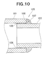
- Fig. 10 is a cross-sectional view of a conventional weld part, wherein the wrought material 103 is inserted in the cast member 101, and both members are joined by lap-fillet MIG welding.
- Gaps 106, 106 must be provided to an inserting portion in order to smoothly insert the wrought material 103 in the cast member 101.
- the cast member 101 is a casting, and therefore inevitably contains gas.
- the melting point of the aluminum alloy casting is lower than the melting point of the aluminum alloy wrought material.
- An object of the present invention is to provide a technique capable of preventing insufficient strength and degraded quality of a weld joint obtained by joining one end of an aluminum or aluminum alloy wrought material to an end part of an aluminum alloy cast member.
- a weld joint of an aluminum alloy member obtained by joining an end part of a wrought material formed of one of aluminum or an aluminum alloy to one end of a cast member formed of an aluminum alloy, wherein the cast member has a chamfer extending from an upper surface of the cast member toward a lower surface until a midway of a thickness of the cast member, and an inserting portion extending along a lower surface of the wrought material from a lower end of the chamfer toward a distal end of the cast member, a distance from the lower end of the chamfer to an end face at one end part of the wrought material is set at 1.0 to 1.7 times a thickness of the wrought material, the chamfer is inclined so that a groove angle with the end face at one end of the wrought material is 15 to 45°, and the groove is welded to cause the inserting portion to act as a backing metal.
- molten metal will leak out because an inserting portion assumes the role of a backing metal.
- the high-melting wrought material can be fully melted because molten metal accumulates in the groove. As a result, strength can be increased and a high-quality weld joint can be obtained.
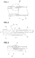
- a pre-weld structure 10 is formed of an aluminum alloy cast member 11 and an aluminum or aluminum alloy wrought material 12, as shown in Fig. 1 . These materials 11, 12 are integrated with each other by MIG welding at a later time.
- a pre-weld groove shape is described in Fig. 2 .
- An end part of the cast member 11 is cut on an incline in the thickness direction to a height H from an upper surface 11a toward a lower surface 11b, as shown in Fig. 2 .
- a section from the lower end to the end face of a chamfer 14 is cut out parallel to the lower surface 11b.
- an inserting portion 13 extending along the lower surface of the wrought material 12 is formed on the end part of the cast member 11.
- the slope 14 is inclined so that a groove angle ⁇ is 15 to 45° in relation to an end face 12a of the wrought material 12.
- the wrought material 12 is separated from the slope 14 so that a root space L is obtained in which the bottom of the groove is 1.0 to 1.7 times the thickness T of the wrought material 12.
- the height H of the slope 14 is somewhat greater than the thickness T of the wrought material 12, as shown in Fig. 2 .
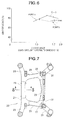
- the horizontal axis in Fig. 5 is the outer-face difference (H-T), and T is 3.5 mm (constant). Therefore, the outer-face difference was 0 when H was 3.5 mm; 1 mm when H was 4.5 mm; and 2 mm when H was 5.5 mm.
- a test piece was cut out from the resulting joint and a tensile test was performed. The tensile strength was 1.13 at an outer-face difference of 1 mm, and 1.03 at an outer-face difference of 2 mm, where the tensile strength was set to 1.0 at an outer-face difference (H-T) of 0.
- the solid line in Fig. 6 shows a case in which the gap is 0, and the dashed line shows a case in which the gap is 1 mm.
- the joint efficiency in the case of the solid line will exceed 70% if the root space is 1.0 (the wrought material thickness was set to 1.0) or greater.
- An opening of 0.5 to 1.0 mm is preferred to facilitate insertion of the cast member 11 in the wrought material 12 in Fig. 1 .
- a root space having points "a” to "b” shown in Fig. 6 in other words, having a wrought material thickness of 1.0 to 1.7, is recommended based on the aforementioned data.
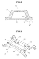
- the subframe 20 as a structure is formed of a front cross part 21 and a rear cross part 22 extending in the crosswise direction of the vehicle, front arm parts 23, 24 extending from both ends of the front cross part 21, rear arm parts 25, 26 extending from both ends of the rear cross part 22, and a left longitudinal part 27 and a right longitudinal part 28 extending in the longitudinal direction of the vehicle and connecting with the front cross part 21 and the rear cross part 22, as shown in Fig. 7 .
- the front cross part 21 and the rear cross part 22, the front arm parts 23, 24 and the rear arm parts 25, 26, and the left longitudinal part 27 and the right longitudinal part 28 are cast members based on an aluminum alloy.
- the front cross part 21 is a channel shape that opens downward, as shown in Fig. 8 .
- a channel has a large hollow portion and can be made lightweight.
- the strength of a hollow cross-section is less than that of a solid cross-section. In terms of strength, the bending stress of the widthwise center part is at the maximum.
- a reinforcing plate 29 is added to the widthwise center part of the front cross part 21, as shown in Fig. 7 .
- the reinforcing plate 29 is a wrought material formed of one of aluminum or an aluminum alloy.
- the reinforcing plate 29 is brought against and welded to the front cross part 21 with the aim of covering the downward opening of the front cross part 21, which is a cast member, as shown in Fig. 8 .
- the end part of the reinforcing plate 29 is the joint shape shown in Fig. 2 , and is joined to the front cross part 21.
- the center part is reinforced by the reinforcing plate 29 in the same manner as the front cross part 22, and the left and right longitudinal parts 27, 28 shown in Fig. 7 .
- the weld joint of the present invention is appropriate for a subframe of a vehicle, but may be used in other weld structures.
- the weld joint of the present invention is appropriate for a subframe of a vehicle.
Landscapes
- Engineering & Computer Science (AREA)
- Mechanical Engineering (AREA)
- Physics & Mathematics (AREA)
- Plasma & Fusion (AREA)
- Chemical & Material Sciences (AREA)
- Materials Engineering (AREA)
- Combustion & Propulsion (AREA)
- Transportation (AREA)
- Arc Welding In General (AREA)
- Body Structure For Vehicles (AREA)
- Butt Welding And Welding Of Specific Article (AREA)
Abstract
Disclosed is a weld joint of an aluminum alloy member formed by joining one end of a wrought material (12) to one end of a cast member (11). The cast member has a chamfer (14), and an inserting portion (13) which extends from the lower end of the chamfer (14) toward the distal end of the case member along the lower surface of the wrought material. The distance (L) from the lower end of the chamfer to the end face (12a) at one end of the wrought material is set equal to 1.0-1.7 times of the thickness (T) of the wrought material, and the chamfer is inclined so that the angle of a groove between the chamfer and the end face (12a) at one end of the wrought material is 15-45°.
Description
- The present invention relates to a weld joint obtained by joining one end of a wrought material formed of one of aluminum and an aluminum alloy to an end part of an aluminum alloy cast member.
- Weld structures formed by joining an aluminum alloy wrought material to an aluminum alloy cast member have been used in actual practice. The technique disclosed in
Patent Literature 1 is a conventional technique relating to such a weld structure. - The weld structure described in
Patent Literature 1 is a subframe. The subframe is manufactured by welding a lid body to a frame body. The frame body is an aluminum alloy cast member, and the lid body is an aluminum alloy wrought material. - The lid body is welded to the frame body along the entire circumference. Because so-called full circumference welding is performed, the welding length is considerably increased and the welding cost is raised. In addition, the welding strain is increased, and the correction cost for correcting the strain is also increased. Manufacturing expenses for the weld structure described in
Patent Literature 1 are therefore increased. - A conventional structure whose manufacturing expenses can be made lower than those in
Patent Literature 1 is described based onFigs. 9 and10 hereof. -
Fig. 9 is a view showing an example of a conventional weld structure, wherein asubframe 100, which is the weld structure, is a square frame obtained by connecting a right-side cast member 101, a left-side cast member 102, and angular tube-shaped wrought materials weld parts 105. - As one way to reduce the weight of a vehicle, the
cast members wrought materials -
Fig. 10 is a cross-sectional view of a conventional weld part, wherein thewrought material 103 is inserted in thecast member 101, and both members are joined by lap-fillet MIG welding. -
Gaps wrought material 103 in thecast member 101. - The
cast member 101 is a casting, and therefore inevitably contains gas. In addition, the melting point of the aluminum alloy casting is lower than the melting point of the aluminum alloy wrought material. - When lap-fillet MIG welding is performed under such conditions, the molten metal runs (leaks) from the
gaps wrought material 103 is more difficult to melt than thecast member 101. - Ensuring a
throat 108 in abead 107 becomes difficult when these main factors overlap. Defects such as insufficient strength and degraded quality of theweld part 105 occur when thethroat 108 is insufficient. -
- Patent Literature 1:
JP-A 2004-210013 - An object of the present invention is to provide a technique capable of preventing insufficient strength and degraded quality of a weld joint obtained by joining one end of an aluminum or aluminum alloy wrought material to an end part of an aluminum alloy cast member.
- According to the present invention, there is provided a weld joint of an aluminum alloy member obtained by joining an end part of a wrought material formed of one of aluminum or an aluminum alloy to one end of a cast member formed of an aluminum alloy, wherein the cast member has a chamfer extending from an upper surface of the cast member toward a lower surface until a midway of a thickness of the cast member, and an inserting portion extending along a lower surface of the wrought material from a lower end of the chamfer toward a distal end of the cast member, a distance from the lower end of the chamfer to an end face at one end part of the wrought material is set at 1.0 to 1.7 times a thickness of the wrought material, the chamfer is inclined so that a groove angle with the end face at one end of the wrought material is 15 to 45°, and the groove is welded to cause the inserting portion to act as a backing metal.
- In the present invention, there is no concern that molten metal will leak out because an inserting portion assumes the role of a backing metal. The high-melting wrought material can be fully melted because molten metal accumulates in the groove. As a result, strength can be increased and a high-quality weld joint can be obtained.
-
-
Fig. 1 is a schematic view showing a wrought material set in a cast member; -
Fig. 2 is an enlarged view ofsection 2 ofFig. 1 ; -
Fig. 3 is a cross-sectional view showing a weld part of a weld joint according to the present invention; -
Fig. 4 is a graph showing a correlation between a groove angle and joint efficiency; -
Fig. 5 is a graph showing a correlation between an outer-face difference and tensile strength; -
Fig. 6 is a graph showing a correlation between a groove space and the joint efficiency; -
Fig. 7 is a top plan view of a weld structure; -
Fig. 8 is a cross-sectional view taken along line 8-8 ofFig. 7 ; -
Fig. 9 is a perspective view showing a conventional weld structure; and -
Fig. 10 is a cross-sectional view of a weld part of the conventional structure. - Embodiments of the present invention will be described below with reference to the attached drawings.
- An embodiment of the present invention will be described with reference to the drawings.
- A
pre-weld structure 10 is formed of an aluminumalloy cast member 11 and an aluminum or aluminum alloy wroughtmaterial 12, as shown inFig. 1 . Thesematerials - A pre-weld groove shape is described in
Fig. 2 . - An end part of the
cast member 11 is cut on an incline in the thickness direction to a height H from anupper surface 11a toward alower surface 11b, as shown inFig. 2 . A section from the lower end to the end face of achamfer 14 is cut out parallel to thelower surface 11b. As a result, aninserting portion 13 extending along the lower surface of thewrought material 12 is formed on the end part of thecast member 11. - The
slope 14 is inclined so that a groove angle θ is 15 to 45° in relation to anend face 12a of thewrought material 12. - The
wrought material 12 is separated from theslope 14 so that a root space L is obtained in which the bottom of the groove is 1.0 to 1.7 times the thickness T of thewrought material 12. - The height H of the
slope 14 is somewhat greater than the thickness T of thewrought material 12, as shown inFig. 2 . - When MIG welding is performed on the groove in this form, there is no concern that molten metal will leak out because the
inserting portion 13 assumes the role of a backing metal. The high-melting wrought material can be fully melted because molten metal accumulates in the groove. As a result, abead 15 such as the one shown inFig. 3 can be obtained. - The evaluation of the
bead 15 was confirmed by an experiment. - An experimental example according to the present invention will be described below. The present invention is not limited to the experimental example.
-
- Aluminum alloy cast member: AC4CH-T5 (ISO Al-Si7Mg), thickness: 8 mm
- Aluminum alloy wrought material: 6NOI-T5, thickness: 3.5 mm
-
- Type: MIG welding
- Filler rod: A5356WY equivalent
- Electric current: 230 A
- Angle of rotation: 75°
- Angle of advance: 15°
- Welding speed: 70 cm/min
-
- Slope height H: 4.5 mm
- Root space L: 5mm
- Groove angle θ: 10°, 15°, 30°, 45°, 50°
- Welding was performed under the above conditions, and the joint efficiency of the resulting joint was calculated. The results are shown in
Fig. 4 . - The best results were produced at θ= 30°, as shown in
Fig. 4 . The generally required joint efficiency is considered to be 70%, but when the efficiency was 80%, which allows for a 10% margin, the groove angle θ was in the range of 15 to 45°. - The relationship between the thickness T of the
wrought material 12 shown inFig. 2 and the height H of theslope 14 was investigated. The results are shown inFig. 5 . - The horizontal axis in
Fig. 5 is the outer-face difference (H-T), and T is 3.5 mm (constant). Therefore, the outer-face difference was 0 when H was 3.5 mm; 1 mm when H was 4.5 mm; and 2 mm when H was 5.5 mm. A test piece was cut out from the resulting joint and a tensile test was performed. The tensile strength was 1.13 at an outer-face difference of 1 mm, and 1.03 at an outer-face difference of 2 mm, where the tensile strength was set to 1.0 at an outer-face difference (H-T) of 0. -
- Gap G: The opening (gap) between the upper surface of the inserting
portion 13 and the lower surface of thewrought material 12 was set to 0, but the experiment was performed on two types of openings, one at 0 mm and the other at 1 mm. - Slope height H: 4.5 mm
- Wrought material thickness T: 3.5 mm
- Root space L: 4 mm (L/T = 1.14), 5 mm (L/T = 1.42), 6 mm (L/T = 1.71)
- Groove angle θ: 30°
- Welding was performed under the above conditions, and the joint efficiency of the resulting joint was calculated. The results are shown in
Fig. 6 . - The solid line in
Fig. 6 shows a case in which the gap is 0, and the dashed line shows a case in which the gap is 1 mm. - Assuming that the required joint efficiency is 70%, the joint efficiency in the case of the solid line will exceed 70% if the root space is 1.0 (the wrought material thickness was set to 1.0) or greater.
- An opening of 0.5 to 1.0 mm is preferred to facilitate insertion of the
cast member 11 in thewrought material 12 inFig. 1 . - When the opening is 1.0 mm, the joint efficiency declines and falls below 70% at the horizontal axis point of 1.7, as shown by the dashed line.
- A root space having points "a" to "b" shown in
Fig. 6 , in other words, having a wrought material thickness of 1.0 to 1.7, is recommended based on the aforementioned data. - An example in which the weld joint of the present invention is used in the subframe of a vehicle is described in
Figs. 7 and8 . - The
subframe 20 as a structure is formed of afront cross part 21 and arear cross part 22 extending in the crosswise direction of the vehicle,front arm parts front cross part 21,rear arm parts rear cross part 22, and a leftlongitudinal part 27 and a rightlongitudinal part 28 extending in the longitudinal direction of the vehicle and connecting with thefront cross part 21 and therear cross part 22, as shown inFig. 7 . - The
front cross part 21 and therear cross part 22, thefront arm parts rear arm parts longitudinal part 27 and the rightlongitudinal part 28 are cast members based on an aluminum alloy. - The
front cross part 21 is a channel shape that opens downward, as shown inFig. 8 . A channel has a large hollow portion and can be made lightweight. However, the strength of a hollow cross-section is less than that of a solid cross-section. In terms of strength, the bending stress of the widthwise center part is at the maximum. - As a countermeasure, a reinforcing
plate 29 is added to the widthwise center part of thefront cross part 21, as shown inFig. 7 . - The reinforcing
plate 29 is a wrought material formed of one of aluminum or an aluminum alloy. The reinforcingplate 29 is brought against and welded to thefront cross part 21 with the aim of covering the downward opening of thefront cross part 21, which is a cast member, as shown inFig. 8 . In other words, the end part of the reinforcingplate 29 is the joint shape shown inFig. 2 , and is joined to thefront cross part 21. - The center part is reinforced by the reinforcing
plate 29 in the same manner as thefront cross part 22, and the left and rightlongitudinal parts Fig. 7 . - The weld joint of the present invention is appropriate for a subframe of a vehicle, but may be used in other weld structures.
- The weld joint of the present invention is appropriate for a subframe of a vehicle.
-
- 10
- Structure
- 11
- Cast member
- 12
- Wrought material
- 12a
- End part of wrought material
- 13
- Inserting portion
- 14
- Slope
- 15
- Bead
- L
- Root space
- T
- Wrought material thickness
- θ
- Groove angle
Claims (1)
- A weld joint of an aluminum alloy member obtained by joining an end part of a wrought material formed of one of aluminum or an aluminum alloy to one end of a cast member formed of an aluminum alloy,
wherein the cast member has a slope extending from an upper surface of the cast member toward a lower surface until a midway of a thickness of the cast member, and an inserting portion extending along a lower surface of the wrought material from a lower end of the slope toward a distal end of the cast member,
a distance from the lower end of the slope to an end face at one end part of the wrought material is set at 1.0 to 1.7 times a thickness of the wrought material,
the slope is inclined so that a groove angle with the end face at one end of the wrought material is 15 to 45°, and
the groove is welded to cause the inserting portion to act as a backing metal.
Applications Claiming Priority (2)
| Application Number | Priority Date | Filing Date | Title |
|---|---|---|---|
| JP2009099265 | 2009-04-15 | ||
| PCT/JP2010/056766 WO2010119925A1 (en) | 2009-04-15 | 2010-04-15 | Weld joint of aluminum alloy member |
Publications (1)
| Publication Number | Publication Date |
|---|---|
| EP2420342A1 true EP2420342A1 (en) | 2012-02-22 |
Family
ID=42982582
Family Applications (1)
| Application Number | Title | Priority Date | Filing Date |
|---|---|---|---|
| EP10764507A Withdrawn EP2420342A1 (en) | 2009-04-15 | 2010-04-15 | Weld joint of aluminum alloy member |
Country Status (5)
| Country | Link |
|---|---|
| US (1) | US20120027506A1 (en) |
| EP (1) | EP2420342A1 (en) |
| JP (1) | JPWO2010119925A1 (en) |
| CN (1) | CN102395443A (en) |
| WO (1) | WO2010119925A1 (en) |
Cited By (1)
| Publication number | Priority date | Publication date | Assignee | Title |
|---|---|---|---|---|
| WO2026057313A1 (en) * | 2024-09-13 | 2026-03-19 | Autotech Engineering S.L. | Chassis component for a motor vehicle, in particular in the form of a subframe, and method of manufacturing such a chassis component |
Families Citing this family (11)
| Publication number | Priority date | Publication date | Assignee | Title |
|---|---|---|---|---|
| US20130266818A1 (en) | 2012-04-10 | 2013-10-10 | Hamilton Sundstrand Corporation | Article including a weld joint |
| CN103615627B (en) * | 2013-11-28 | 2015-09-16 | 攀钢集团攀枝花钢钒有限公司 | Power station boiler economizer leakage processing method |
| EP3096916A4 (en) * | 2014-01-24 | 2017-11-22 | Electric Power Research Institute, Inc. | Stepped design weld joint preparation |
| JP2016198811A (en) * | 2015-04-14 | 2016-12-01 | ジャパンマリンユナイテッド株式会社 | Butt welding structure and butt welding method for extremely thick steel plate |
| CN104858535A (en) * | 2015-05-18 | 2015-08-26 | 上海交通大学 | Connection method for improving strength of overlap joints |
| JP6709638B2 (en) * | 2016-03-10 | 2020-06-17 | 日立造船株式会社 | Welding method of steel pipe and joint in steel pipe structure |
| CN106514029B (en) * | 2016-12-20 | 2019-05-14 | 东方电气集团东方锅炉股份有限公司 | The method of long tube end built-up welding |
| CN107127452A (en) * | 2017-06-27 | 2017-09-05 | 东莞市纳百川电子科技有限公司 | A kind of metal welding procedure |
| DE102017119677A1 (en) * | 2017-08-28 | 2019-02-28 | Doduco Solutions Gmbh | Method for producing a lap-over composite material from sheet metal |
| EP3838722B1 (en) * | 2019-12-20 | 2022-03-16 | Autotech Engineering Deutschland GmbH | Subframe for a motor vehicle |
| CN114473275A (en) * | 2021-12-31 | 2022-05-13 | 上海集度汽车有限公司 | Vehicle frame, welding joint structure and manufacturing method thereof |
Family Cites Families (17)
| Publication number | Priority date | Publication date | Assignee | Title |
|---|---|---|---|---|
| US2324335A (en) * | 1940-12-20 | 1943-07-13 | Taylor Edward Hall | Pipe joint |
| US2895747A (en) * | 1955-05-31 | 1959-07-21 | Standard Oil Co | Welded aluminum coated tubular member and method of making same |
| US3195229A (en) * | 1962-05-21 | 1965-07-20 | Foster Wheeler Corp | Method of butt welding metal tubes |
| US3790120A (en) * | 1971-12-13 | 1974-02-05 | Flexicore Co | Composite slab casting form |
| US4182950A (en) * | 1973-10-11 | 1980-01-08 | Boros Lawrence A | Deep fill welding joint configuration and welding method |
| JPS5841946B2 (en) * | 1976-02-10 | 1983-09-16 | 三菱電機株式会社 | Thick plate welding method in MIG welding |
| JPS56119667A (en) * | 1980-02-26 | 1981-09-19 | Nippon Steel Corp | Method for prevention of formation of weld defects |
| JPS5736093A (en) * | 1980-08-13 | 1982-02-26 | Tokushu Piston Seisakusho:Kk | Production of plunger |
| JPS6064777A (en) * | 1983-09-16 | 1985-04-13 | Daihatsu Motor Co Ltd | Method for welding expanded aluminum member to aluminum die casting member |
| JPH07115174B2 (en) * | 1986-09-19 | 1995-12-13 | スズキ株式会社 | Autoby frame welding structure |
| JP3151696B2 (en) * | 1994-05-10 | 2001-04-03 | 日本軽金属株式会社 | Aluminum drive shaft |
| JP3402550B2 (en) * | 1996-01-30 | 2003-05-06 | 日産自動車株式会社 | Groove for welded joint |
| JP3945852B2 (en) * | 1997-03-18 | 2007-07-18 | 株式会社神戸製鋼所 | Joint structure for automotive structural members |
| FR2807682A1 (en) * | 2000-04-17 | 2001-10-19 | Soudure Autogene Francaise | Metal-inert-gas and metal-active-gas welding of tubular components involves positioning a flange jutting out from lateral surface of the edge of one component into recess in lateral surface of edge of other component |
| JP2004210013A (en) | 2002-12-27 | 2004-07-29 | Showa Denko Kk | Hollow frame for vehicle and vehicle |
| JP4786378B2 (en) * | 2006-03-14 | 2011-10-05 | 三菱重工業株式会社 | Piping joint structure |
| JP2007283348A (en) * | 2006-04-14 | 2007-11-01 | Komatsu Ltd | Welding method and ring gear member welded thereby |
-
2010
- 2010-04-15 US US13/264,617 patent/US20120027506A1/en not_active Abandoned
- 2010-04-15 CN CN2010800167391A patent/CN102395443A/en not_active Withdrawn
- 2010-04-15 EP EP10764507A patent/EP2420342A1/en not_active Withdrawn
- 2010-04-15 WO PCT/JP2010/056766 patent/WO2010119925A1/en not_active Ceased
- 2010-04-15 JP JP2011509349A patent/JPWO2010119925A1/en not_active Withdrawn
Non-Patent Citations (1)
| Title |
|---|
| See references of WO2010119925A1 * |
Cited By (1)
| Publication number | Priority date | Publication date | Assignee | Title |
|---|---|---|---|---|
| WO2026057313A1 (en) * | 2024-09-13 | 2026-03-19 | Autotech Engineering S.L. | Chassis component for a motor vehicle, in particular in the form of a subframe, and method of manufacturing such a chassis component |
Also Published As
| Publication number | Publication date |
|---|---|
| WO2010119925A1 (en) | 2010-10-21 |
| US20120027506A1 (en) | 2012-02-02 |
| JPWO2010119925A1 (en) | 2012-10-22 |
| CN102395443A (en) | 2012-03-28 |
Similar Documents
| Publication | Publication Date | Title |
|---|---|---|
| EP2420342A1 (en) | Weld joint of aluminum alloy member | |
| EP2324947A1 (en) | Hollow curved structures formed with friction stir welding ; Method of manufacturing such structures | |
| JP2005153630A (en) | Headrest support structure | |
| KR20180031048A (en) | Fillet welding method and fillet welded joint | |
| CN109131566A (en) | The welding method of the bridging arrangement and cross of vehicle beam and stringer, stringer | |
| US8172125B2 (en) | Vehicle door frame and method of producing the same | |
| JP6065147B1 (en) | Joint structure of lap fillet arc welded joints and press-formed parts | |
| EP3257612B1 (en) | Lap fillet arc-welded joint | |
| CN106853846A (en) | Car body component | |
| CN111959244B (en) | Method for manufacturing side door for vehicle, door component, and side door | |
| JP4562677B2 (en) | Welded structure closed section frame | |
| JP2013139047A (en) | Weld joint part of steel member | |
| JPH101068A (en) | Member connection structure of frame body | |
| US20190256155A1 (en) | Vehicle pillar structure and method for manufacturing vehicle pillar | |
| JP2000199240A (en) | Hydraulic excavator boom structure | |
| US11253956B2 (en) | Structure having stress protected groove weld and structural members forming the same | |
| JP7841522B2 (en) | Joining structure and joining method for vehicle components | |
| JP4933923B2 (en) | Dissimilar material joining method | |
| US20240139880A1 (en) | Arc spot welding method for joining dissimilar materials and weld joint of dissimilar materials | |
| CN110001699A (en) | Rail vehicle truck | |
| JP2006347358A (en) | Railway frame structure | |
| US9981584B2 (en) | Method of reinforcing a seatback frame of a seat assembly | |
| JP5708536B2 (en) | Vehicle roof structure | |
| JP5900189B2 (en) | Welded joint of steel and method of forming welded joint | |
| JP4560288B2 (en) | Welding method |
Legal Events
| Date | Code | Title | Description |
|---|---|---|---|
| PUAI | Public reference made under article 153(3) epc to a published international application that has entered the european phase |
Free format text: ORIGINAL CODE: 0009012 |
|
| 17P | Request for examination filed |
Effective date: 20111104 |
|
| AK | Designated contracting states |
Kind code of ref document: A1 Designated state(s): AT BE BG CH CY CZ DE DK EE ES FI FR GB GR HR HU IE IS IT LI LT LU LV MC MK MT NL NO PL PT RO SE SI SK SM TR |
|
| DAX | Request for extension of the european patent (deleted) | ||
| STAA | Information on the status of an ep patent application or granted ep patent |
Free format text: STATUS: THE APPLICATION HAS BEEN WITHDRAWN |
|
| 18W | Application withdrawn |
Effective date: 20130114 |