EP2420005B1 - Method and device for data processing in a communication network - Google Patents
Method and device for data processing in a communication network Download PDFInfo
- Publication number
- EP2420005B1 EP2420005B1 EP10713934.7A EP10713934A EP2420005B1 EP 2420005 B1 EP2420005 B1 EP 2420005B1 EP 10713934 A EP10713934 A EP 10713934A EP 2420005 B1 EP2420005 B1 EP 2420005B1
- Authority
- EP
- European Patent Office
- Prior art keywords
- base station
- mobile terminal
- information
- feedback information
- channel
- Prior art date
- Legal status (The legal status is an assumption and is not a legal conclusion. Google has not performed a legal analysis and makes no representation as to the accuracy of the status listed.)
- Active
Links
Images

Classifications
-
- H—ELECTRICITY
- H04—ELECTRIC COMMUNICATION TECHNIQUE
- H04B—TRANSMISSION
- H04B7/00—Radio transmission systems, i.e. using radiation field
- H04B7/02—Diversity systems; Multi-antenna system, i.e. transmission or reception using multiple antennas
- H04B7/022—Site diversity; Macro-diversity
- H04B7/024—Co-operative use of antennas of several sites, e.g. in co-ordinated multipoint or co-operative multiple-input multiple-output [MIMO] systems
-
- H—ELECTRICITY
- H04—ELECTRIC COMMUNICATION TECHNIQUE
- H04B—TRANSMISSION
- H04B7/00—Radio transmission systems, i.e. using radiation field
- H04B7/02—Diversity systems; Multi-antenna system, i.e. transmission or reception using multiple antennas
- H04B7/04—Diversity systems; Multi-antenna system, i.e. transmission or reception using multiple antennas using two or more spaced independent antennas
- H04B7/0413—MIMO systems
- H04B7/0452—Multi-user MIMO systems
-
- H—ELECTRICITY
- H04—ELECTRIC COMMUNICATION TECHNIQUE
- H04B—TRANSMISSION
- H04B7/00—Radio transmission systems, i.e. using radiation field
- H04B7/02—Diversity systems; Multi-antenna system, i.e. transmission or reception using multiple antennas
- H04B7/04—Diversity systems; Multi-antenna system, i.e. transmission or reception using multiple antennas using two or more spaced independent antennas
- H04B7/0413—MIMO systems
- H04B7/0456—Selection of precoding matrices or codebooks, e.g. using matrices antenna weighting
- H04B7/046—Selection of precoding matrices or codebooks, e.g. using matrices antenna weighting taking physical layer constraints into account
- H04B7/0465—Selection of precoding matrices or codebooks, e.g. using matrices antenna weighting taking physical layer constraints into account taking power constraints at power amplifier or emission constraints, e.g. constant modulus, into account
-
- H—ELECTRICITY
- H04—ELECTRIC COMMUNICATION TECHNIQUE
- H04B—TRANSMISSION
- H04B7/00—Radio transmission systems, i.e. using radiation field
- H04B7/02—Diversity systems; Multi-antenna system, i.e. transmission or reception using multiple antennas
- H04B7/04—Diversity systems; Multi-antenna system, i.e. transmission or reception using multiple antennas using two or more spaced independent antennas
- H04B7/06—Diversity systems; Multi-antenna system, i.e. transmission or reception using multiple antennas using two or more spaced independent antennas at the transmitting station
- H04B7/0613—Diversity systems; Multi-antenna system, i.e. transmission or reception using multiple antennas using two or more spaced independent antennas at the transmitting station using simultaneous transmission
- H04B7/0615—Diversity systems; Multi-antenna system, i.e. transmission or reception using multiple antennas using two or more spaced independent antennas at the transmitting station using simultaneous transmission of weighted versions of same signal
- H04B7/0619—Diversity systems; Multi-antenna system, i.e. transmission or reception using multiple antennas using two or more spaced independent antennas at the transmitting station using simultaneous transmission of weighted versions of same signal using feedback from receiving side
- H04B7/0621—Feedback content
- H04B7/0626—Channel coefficients, e.g. channel state information [CSI]
Definitions
- the invention relates to a method and to a device for data processing in a communication network.
- Multiple antenna systems allow for an active exploitation of the spatial degrees of freedom in order to increase the spectral efficiency and to boost throughput in wireless communication systems.
- spatial separation of simultaneously transmitted data streams can be performed either at the transmit or at the receive side depending on the available channel state information (CSI) and the capabilities of joint signal processing.
- CSI channel state information
- MIMO signal processing on link level utilizes spatial multiplexing or space-division multiple access (SDMA) according to IEEE 802.11n, WiMAX and 3G Long Term Evolution (3G-LTE).
- SDMA space-division multiple access
- MIMO capable systems connecting a base station and several mobile terminals are deployed in a cellular environment
- interference between cells using the same radio resources becomes a limiting factor.
- the concept of MIMO signal separation can be applied for active interference management.
- any suppression of interference from adjacent cells is a key issue in cellular mobile communication systems.
- the MIMO concept has to be extended to a higher number of antennas involved in the joint signal processing thereby increasing a computational complexity and inflicting challenges regarding distributed channel data collection and coherent signal transmission or reception at antenna locations which may be deployed at a distance of more than 1000 meters.
- Methods for collecting CSI from distributed mobile terminals usually depend on a transceiver design and on a selection of algorithms.
- a receiver estimates a signal quality matrix from a transmitted signal, compares it with a target metric and determines an offset value which in turn it transmits to the transmitter so that it can use the offset value to adjust its transmission rate so that the target metric can be achieved.
- the problem to be solved is to overcome the disadvantages as mentioned above and in particular to introduce a mechanism that allows for an efficient utilization of feedback information, in particular CSI data, provided by mobile terminals.
- a method for data processing by a mobile terminal comprising several antennas in a communication network comprising multiple base stations organized as a collaboration area in particular providing a coherent transmission, comprising the steps of:
- said feedback information is a combined (in particular compressed) and therefore reduced information thereby leading to a significant reduction of signaling traffic between the mobile terminal and the at least one base station.
- the feedback information provided by the mobile terminal can be used for interference management, in particular for reducing an interference of a collaboration area utilizing joint transmission.
- each mobile terminal may comprise one antenna or several antennas.
- the mobile terminal processes feedback information to several base stations, e.g., to two base stations thereby allowing the mobile terminal to maintain two active connections and/or two channels with different base stations. This, however, applies in general for several connections and/or channels.
- the mobile terminal referred to may be any mobile device with a radio interface, in particular any mobile phone, UE, personal digital assistant, computer or processing unit.
- the base station referred to may be any radio station arranged to serve a mobile terminal.
- the base station may be a NodeB an eNodeB or any access point with a radio interface that can be utilized by the mobile terminal.
- the base stations may be connected with one another, e.g., via an X2 interface.
- said feedback information comprises channel state information (CSI).
- CSI channel state information
- the mobile terminal comprises several antennas, utilizing at least one antenna for interference suppression purposes.
- beamforming can be utilized via said several antennas of the mobile terminal thereby amplifying the signal and reducing any interference.
- the feedback information is conveyed to the mobile terminal's serving base station.
- the feedback information can be provided to each of its serving base stations.
- the base station distributes the feedback information to at least one further base station and/or to a central unit, wherein the base station and the at least one further base station and/or the central unit aware of the feedback information perform a joint processing, in particular a pre-coder calculation.
- the several base stations performing a joint pre-coder calculation may establish a collaboration area.
- Such collaboration area can be determined based on the feedback information provided by the mobile terminal (or based on feedback information provided by several mobile terminals).
- the amount of feedback information fed to the base stations of a collaboration area is significantly reduced due to the processing (e.g., combining) suggested by this approach.
- the base stations of the collaboration area may provide efficient interference processing, e.g., zero forcing or any other type of channel orthogonalization, allowing an improved data processing within the collaboration area at a reduced amount of signaling overhead due to the processed feedback information.
- the mobile terminal based on the input signal may conduct a virtual pre-coding and provide such feedback information to it serving base station.
- the serving base station then becomes aware of an actual pre-coding that would be beneficial for this particular mobile terminal.
- the pre-coding provided by the base station can be triggered by the mobile terminal.
- the base station may consider several such virtual pre-coding suggestions by several mobile terminals to provide a beneficial overall pre-coding.
- the at least one base station may have or provide a set of pre-coder (codebook) and the mobile terminal may conduct virtual pre-coding based on such codebook information.
- the mobile terminal can choose one pre-coder from the set of pre-coders that complies with its needs best.
- the mobile terminal may report its effective radio channel for this selected pre-coder.
- the at least one base station has several antennas.
- a beamforming or pre-coding can be achieved, which can be improved based on the feedback information processed at the mobile terminal(s).
- the input signal is a reference signal conveyed via several antennas of the at least one base station.
- the at least one base station conducts pre-coding and/or beamforming based on the feedback information obtained by the mobile terminal.
- the at least one base station conveys a first type of input signals with a high amount of information infrequently and a second type of input signals with a reduced amount of information frequently.
- the high amount of information can be conveyed towards the mobile terminal(s) and with each frame (10ms) the reduced amount of information may be conveyed in a pre-coded manner to a particular mobile terminal.
- the first type of input signals can be conveyed via all antennas of a base station and the second type of input signals can be conveyed in a beamforming manner utilizing, e.g., only a selection of antennas in a predefined way.
- the feedback information comprises a first type of feedback information with a high amount of information conveyed infrequently and a second type of feedback information with a reduced amount of information conveyed frequently.
- the feedback information can be conveyed to the at least one base station in a similar manner.
- the first type of feedback information can be conveyed via several antennas of the mobile terminal, whereas the second type of feedback information can be conveyed in a beamforming manner utilizing the mobile terminal's antennas in a predefined way.
- At least two base stations are organized as a collaboration area in particular providing a coherent transmission.
- the base stations of a collaboration area provide distributed processing.
- the input signals from the at least one base station are at least partially orthogonal to one another.
- the mobile terminal provides the feedback information via a multiple-input single-output channel processing, wherein the mobile terminal in particular selects a receive strategy.
- the mobile terminal may select its receive strategy based on its processing capabilities, in particular independent from other receive strategies of other mobile terminals.
- the mobile terminal may also consider external interference that could be determined via at least one of its antennas, and process such information into the combined feedback information to be conveyed to the at least one base station.
- a device comprising a and/or being associated with a processor unit and/or a hard-wired circuit and/or a logic device that is arranged such that the method as described herein is executable thereon.
- the device is a communication device, in particular a or being associated with a mobile terminal or a base station.
- a central network component which may be a functional entity deployed with a particular base station
- the device mentioned may be a base station with such a central network component or even a central network component deployed as a physical entity.
- CA collaboration area
- MTs mobile terminals
- Receive antennas at a mobile terminal can be used jointly for data detection as well as interference suppression. Each user may apply for one data stream. However, it is also an option to support multiple data streams per user. In such case, the mobile terminals may provide multiple MISO feedback channels.
- each user may independently select its preferred receive strategy (i.e. select Rx antenna(s), select MRC and/or IRC and utilize receive filter accordingly) and convey the effective MISO channel apparent behind the receive filter.
- select Rx antenna(s) i.e. select MRC and/or IRC and utilize receive filter accordingly
- MISO channel apparent behind the receive filter i.e. select MRC and/or IRC and utilize receive filter accordingly
- Each mobile terminal then determines the channel coefficients and then reports them to the serving base station (BS).
- the BS distributes these then among the BS within the CA.
- the BSs then perform a joint pre-coder calculation in a parallel manner, reducing additional exchange of pre-coder weights and minimizing delay over the connecting link between BSs.
- a final coordinated and joint application of these pre-coder weights allows suppression of intra-cell interference and coherent joint transmission of data-streams from distributed antennas.
- the approach suggested applies in particular for systems using CSI-based pre-coding and/or beamforming irrespective of whether or not base station sectors are collaborating.
- a framework for feedback provisioning from at least one mobile terminal to at least one base station is considered.
- the solution provided in particular utilizes an MISO channel and each mobile terminal may select a receive strategy independently from any other mobile terminal. Such selection can be conducted based on the computational capability of the respective mobile terminal.
- a multi-cell channel information may be fed back to at least one base station after receiver processing by the mobile terminal.
- Several base stations can be combined to a collaboration area (CA).
- Distributed processing can be provided by each base station thereby facilitating a real-time implementation.
- a mobile terminal 201 comprises two antennas 203, 204, a receive filter w 1 and provides a MISO channel feedback h MT 1 to a base station BS 1 .
- a mobile terminal 202 comprises two antennas 205, 206, a receive filter w 2 and provides a MISO channel feedback h MT 2 to a base station BS 2 .
- the base stations BS 1 and BS 2 both perform a coherent joint transmission 207 processing the whole pre-coder C CA 1 on the given user feedback, but using the corresponding respective parts C 1 C A i and C 2 C A i for coherent joint transmission.
- Each base station BS 1 and BS 2 in Fig.2 comprises two antennas 208, 209 and 210, 211 that are fed via a pre-coding matrix C 1 , C 2 for each base station BS 1 and BS 2 .
- the antennas of Fig.2 communicate via a radio channel 212 described as H i C i indicating a collaborative area i.
- each sector is allowed to use independent unitary beamformers C 1 , C 2 in case of non-collaborative transmission.
- each MT provides feedback on its effective MISO channel, seen among several BS antennas.
- BS collaboration increases the number of antennas from the perspective of signal processing.
- multi-antenna MTs SDMA with a single data stream per user may be the dominant transmission mode in multi-user systems.
- providing feedback via a single data stream may suffice for a user and will save a significant amount of feedback overhead.
- each MT may process a MISO channel and may provide feedback information about thereof to its serving BS.
- each MT may use linear receive filters to report an effective MISO to its serving base station.
- the effective MISO channel may be determined based on several input signals from one BS or several BSs.
- Each BS may provide several input signals via several antennas.
- the BSs may be of one CA, but can also be of different CAs. In particular a reference signal from a BS that is not part of the current CA can be utilized for beam forming purposes at the MT.
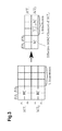
- Fig.3 shows a schematic diagram that illustrates a transforming of a MIMO channel into an effective MISO channel with known SINR.
- Said effective MISO channel is conveyed as feedback information to the MT's serving BS.
- the MIMO channel H i m received via two antennas at the respective MT m from two BSs is combined into said effective MISO channel h i m .
- each MT may choose at least one of the following approaches, in particular its receive filter(s), according to its own computational capabilities:
- Each BS in the collaborative area may use a pre-selected algorithm for user orthogonalization purposes and may be able to determine pre-coding weights in a distributed way.
- frequency resources may be reused in all neighboring cells.
- the MT may receive interfering signals destined for other users in addition to its own desired signal.
- all BSs may provide ⁇ fixed unitary beam sets C ⁇ , ⁇ ⁇ ⁇ 1, ..., ⁇ ⁇ .
- Each beam set may comprise ⁇ N T fixed pre-coding vectors (beams) b ⁇ ,u with u ⁇ ⁇ 1, ..., ⁇ N T ⁇ , where ⁇ denotes a size of a collaboration area (CA).
- Beams fixed pre-coding vectors
- Each BS-cluster i may independently select one of these beam sets.
- Each sector may use N T beams, denoted by b i,u as the u-th pre-coding vector used by cluster i.
- the desired data stream x i,u transmitted on the u-th beam from the i-th cluster is distorted by the intra-cluster and inter-cluster interference aggregated in ⁇ i,u and z i,u , respectively.
- H i m spans the N R ⁇ ⁇ N T channel matrix for user m formed by the cluster i.
- ⁇ i,u denotes an interference generated in the cooperation area.
- the ⁇ N T beams in the beam set C i may simultaneously be active, wherein an available power p i is assumed to be uniformly distributed over the ⁇ N T beams.
- a cluster of BS antennas may be grouped for joint signal pre-processing and a coherent transmission of data signals and a cooperation area (CA) may be defined.
- the CA may manage interference by utilizing joint signal processing prior to transmission over the wireless channel. Data signals coming from outside this CA will be treated as inter-cluster interference, where the spatial structure can be measured, e.g., by estimation of the interference co-variance matrix.
- CAs can be selected network-centric or user-centric. The user-centric choice can be determined, e.g., by measuring broadband channels to nearby BSs and by reporting a set of strongest BS antennas to the MT's serving BS.
- the serving BS may initialize the setup of a new CA or allocate this particular MT into a user group served inside a predefined CA.
- the overlap of CAs including different BS antenna combinations can be separated, e.g., in a frequency domain by means of resource partitioning.
- a collaborative pre-coder C CA 1 can be modified to any kind of beamforming as shown in Fig.2 .
- Each collaborating BS in the CA determines in a distributed manner the whole pre-coder C CA 1 on the given user feedback utilizing the corresponding respective parts C 1 C A i and C 2 C A i for coherent joint transmission.
- Fig.2 shows a pre-coding for coherent joint transmission that is determined in a distributed fashion by two base stations, wherein the corresponding parts thereof are provided by each of the collaborating BSs.
- each MT may provide limited or full CSI to the BSs.
- CSI feedback overhead may advantageously be decreased saving valuable uplink resources. Therefore, a MT-assisted channel pre-processing is suggested.
- MU-MIMO multi-user MIMO
- the MMSE receiver may be aware of interference either by having a full knowledge, i.e. spatial structure, or a partial knowledge, i.e. a power on the inter-cluster interference may be considered.
- each MT can choose its desired receive strategy independently from any other MT according to its computational capabilities and knowledge on channel state information at the receiver (CSIR) including interference.
- CSIR channel state information at the receiver
- Agreed assumptions between the MTs and the CA may be based on the fact that a minimum intra-cluster interference pre-coder is applied.
- the performance of different linear receivers to obtain an effective channel can be different after zero-forcing (ZF) pre-coding at the BSs.
- ZF zero-forcing
- each MT pre-computes an effective multiple-input-single-output (MISO) channel and reports this to the serving BS in the cooperation area.
- MISO multiple-input-single-output
- the BS may use different methods for user orthogonalization, e.g., linear pre-coding as ZF, MMSE or block diagoninalization (BD) or non-linear Tomlinson-Harashima pre-coding (THP).
- the MISO channel h MT m received at the m-th MT can be fed back to the base station in addition a SINR value.
- the MT may not have any possibility to compensate inter-cluster interference, which limits the SINR.
- the CA may provide the data stream to a particular MT m , while all other data streams used for residual MTs are orthogonalized by use of the ZF pre-coder.
- the MTs in the cluster do not experience any intra-cluster interference.
- ⁇ MT m is a transmit power scaling factor applied on the data stream send to the m-th MT
- ⁇ N 2 is a noise power received at the single Rx antenna.
- ⁇ MT 1 1 if no transmit power limit is applied, ⁇ MT 1 equals 1. The entire path-loss is pre-compensated at the transmitter, resulting in unit signal power at the receive antenna.
- sectors may operate independently from one another while inter-cell interference is accounted for at the multi-antenna MT.
- Each BS may provide a fixed matrix C comprising unitary DFT beams. Assuming that the inter-cell interference is completely known at each MT, the MTs evaluate the achievable rate per beam and convey this information to their serving BS. At the BS, the feedback from different MTs is collected, and the DFT beams from the matrix C are assigned individually to the MT.
- the MTs are assumed to provide their preferred matrix index (PMI) and the corresponding SINR.
- a co-channel interference (CCI) amounting to ⁇ i , u + z i , u becomes predictable, enabling an interference-aware scheduling in a cellular system.
- CCI co-channel interference
- users may benefit from almost doubled spectral efficiencies in the MIMO 2 ⁇ 2 system compared to the SISO setup.
- the MTs considered are equipped with multiple Rx antennas for the purpose of IRC.
- the BSs are assumed to provide N T data streams to N T MTs.
- the MTs may use linear receive filters to transform the MIMO channel into an effective MISO channel, according to Fig.3 .
- the MT may provide feedback regarding an achievable SINR and the effective MISO channel h MT m .
- a linear receive filter w u MMSE can be determined by assuming DFT-based pre-coding for intra-cluster and inter-cluster signals.
- a ZF pre-coder among the collaborative Tx antennas may remove the intra-cluster interference, while keeping the inter-cluster interference on a low level.
- This approach may profit from a pre-selection of suitable resources. Further, gains from IRC are kept in the system.
- the MT is not required to have high computational power, e.g., to do a singular value decomposition (SVD) on the measured collaborative channel H i .
- SMD singular value decomposition
- Each MT may apply for a single data stream only, i.e. for a single MU-MIMO service.
- a dominant eigenmode can be selected, i.e. the eigenvector corresponding to the highest eigenvalue.
- the MTs may preferably be grouped such that their eigenmodes show a high orthogonality, in particular the highest possible orthogonality. This allows for an efficient power reduction.
- the linear receive filter is determined based on an assumption of eigenmode pre-coding for the dedicated data stream and DFT-based pre-coding for inter-cluster signals.
- w u MMSE p i Q i ⁇ R yy - 1 ⁇ H i ⁇ v i , 1 ⁇ h ⁇ i , u
- the initial spatial channel assumption concentrates on outside interference as the limiting interference contribution, while the effective MISO channel inside the cooperation area is chosen such that the desired signal from the set of BSs to the MT is maximized.
- the final SINR can thus be fully pre-computed at the BS, since the initial SINR reported from the MT under ideal pre-coding using the dominant eigenbeam forming (DEBF) will be altered by the power normalization per transmission stream only.
- DEBF dominant eigenbeam forming
- the true multi-cell channel H i from (all) BSs to a given terminal m may be estimated.
- Pre-coding matrices may not change frequently in order to keep multi-cell interference predictable.
- a first channel estimation based on multi-cell pilot symbols is required at this step to determine H i C i .
- h MT m may be determined as set forth above. Also, pilot symbols may be processed like data by the receive filter. Hence, the effective MISO channel can directly be estimated on such a common reference signal.
- reporting a virtual MISO channel is of advantage and can be orthogonalized by the collaborative BSs like a single antenna receiver.
- the pre-coder and its power normalization are determined by the used algorithm, which may preferably be the same on all distributed processing units. It may be of advantage in case the same software and/or hardware is utilized on all processing units of a CA.
- Each MT in the active set of users on a single data stream may be served while the Rx antennas are used for IRC purposes.
- a maximum number of ⁇ N T MISO channels experienced from different MTs are composed to form a compound virtual MIMO channel of a size N T ⁇ N T .
- a compound channel matrix can be orthogonalized by any linear or non-linear pre-coding technique, if a full rank is assured. This may be the case in a multi-point to multi-point channel.
- the proposed approach allows to benefit from two major advantages: First, the multiple receive antennas are efficiently used for suppression of external interference at the MT's side. Second, by reducing the number of data streams per MT, the degrees of freedom in multi-user grouping can be utilized such that the number of all active data streams is smaller than or equal to the number of active transmit antennas.
- a cross-check of all contents in particular regarding the origin (MT and BS identifier) and a time stamp (frame number and optionally sub-frame number) is conducted.
- all valid CSI data can be loaded in a pre-determined order, assuring that the compound channel matrices put together at different BSs are identical in each entry. This can be assured per sub-carrier or per physical RB in OFDM systems where transmit collaboration is applied.
- the pre-determined order can be achieved by numbering all active BS Tx antennas within the CA while keeping track of the corresponding MT identifier. This antenna numbering is advantageously known to all MTs.
- the (in particular all) BSs distribute via multi-cast a correctly received CSI message to the (in particular to all) BSs of the CA.
- one BS has incomplete data, e.g., due to packet loss, other BSs within the CA can provide the missing pre-coder weights and the calculation of the post-detected SINR. This ensures that joint spatial pre-processing can still successfully be performed.
- MCS modulation and coding scheme
- the pre-coder matrix is column-wise normalized such that the average transmitted power per data stream is (substantially) constant. On the average and considering slightly different phases and amplitudes over the entire frequency range of the OFDM symbol, a rather constant transmit power per Tx antenna can be reached as well. Since the normalization for all elements of one and the same pre-coder column is the same, the resulting SNRs post-detected per data stream can be normalized differently.
- each BS knows which row out of the finally calculated joint pre-coder matrix belongs to its own transmit antennas. This particular row is selected and stored for further processing together with the user data which are expected for each user to arrive via multi-cast messaging on the X2 interface.
- the time stamp allows for a synchronization of pre-coder and data content, which is beneficial for successful coherent transmission of data and active interference management within the CA.
- each MT reports the effective post-equalization SINR.
- the final SINR can be determined or predicted after ZF pre-coding applying the pre-chosen receive filter per MT.
- the normalization factors ⁇ MTm for the m-th column of the spatial pre-coder and therefore for the data stream to the m-th MT can be calculated and multiplied with the reported SINR per MT.
- the calculation of the final post-detection SINR considering joint transmit pre-coding and the reported effective SINR from each MT can again be calculated in a distributed fashion by the serving BS of each MT.
- This BS is in charge of the current and future continuation of higher layer protocols, such as HARQ.
- a MCS level, a puncturing and a PDU size can be chosen such that each spatial layer is utilized for data transmission purposes.
- puncturing is a method that allows reducing a forward error correction code for a first transmission.
- the overhead portion based on such forward error correction code can be reduced thereby increasing the bandwidth to be utilized for user data.
- additional redundancy information is conveyed in a second transmission.
- Puncturing Such shortening of the redundancy information (here: the forward error correction code) in the first transmission is referred to as "puncturing”.
- the whole method can be referred to as hybrid ARQ.
- the chosen MCS level for each spatial layer is tagged to an associated encoded data stream and is again multi-casted to each BS belonging to the active set of antennas in the CA, which will perform mapping onto higher modulation formats locally and the mapping to the correct spatial pre-coder input queue.
- the MTs may in parallel be informed about the allocated resources and the MCS levels. Since resource allocation announcement is in charge of the serving BS for each MT, this can either be done in a cooperative transmit mode or in a non-cooperative mode per BS.
- the joint MIMO channel between the BS and the MT antennas can be treated as a standard point-to-multi-point MIMO channel.
- the spatial signal separation is performed at the BS antennas based on the known CSI.
- adaptive spatial pre-coding the interference inside the CA can be reduced and - in a best-case scenario - an intra-cluster interference-free transmission may be achieved.
- the residual inter-cluster interference may limit the performance of the CA. Thus, it can be focused on a joint SINR maximization including the spatial structure of the inter-cluster interference.
- each BS in the CA aggregates the interfering MISO channels h MT n with n ⁇ 1 , ... , m - 1 , m + 1 , ... , ⁇ ⁇ N T , according to the BD approach.
- This results in a matrix of a dimension ( ⁇ N T - 1) ⁇ ⁇ N T h ⁇ MT m h MT 1 H ... h MT m - 1 H ⁇ h MT m + 1 H ... h MT ⁇ ⁇ N T H H H
- h ⁇ MT m U ⁇ m ⁇ ⁇ m 0 ⁇ U ⁇ m 1 v ⁇ m 0 H
- v ⁇ m 0 corresponds to the eigenvector associated with the null space of h MT m .
- null space can be represented by a matrix of a dimension ⁇ ⁇ ⁇ N T .
Landscapes
- Engineering & Computer Science (AREA)
- Computer Networks & Wireless Communication (AREA)
- Signal Processing (AREA)
- Mobile Radio Communication Systems (AREA)
Description
- The invention relates to a method and to a device for data processing in a communication network.
- Multiple antenna systems allow for an active exploitation of the spatial degrees of freedom in order to increase the spectral efficiency and to boost throughput in wireless communication systems.
- Furthermore, spatial separation of simultaneously transmitted data streams can be performed either at the transmit or at the receive side depending on the available channel state information (CSI) and the capabilities of joint signal processing.
- MIMO signal processing on link level utilizes spatial multiplexing or space-division multiple access (SDMA) according to IEEE 802.11n, WiMAX and 3G Long Term Evolution (3G-LTE).
- If MIMO capable systems connecting a base station and several mobile terminals are deployed in a cellular environment, interference between cells using the same radio resources becomes a limiting factor. The concept of MIMO signal separation can be applied for active interference management. However, any suppression of interference from adjacent cells is a key issue in cellular mobile communication systems. Hence, if multiple base stations collaborate, the MIMO concept has to be extended to a higher number of antennas involved in the joint signal processing thereby increasing a computational complexity and inflicting challenges regarding distributed channel data collection and coherent signal transmission or reception at antenna locations which may be deployed at a distance of more than 1000 meters.
- Methods for collecting CSI from distributed mobile terminals (MTs) usually depend on a transceiver design and on a selection of algorithms.
- "Resource Management in Cooperative MIMO-OFDM Cellular systems", Antti Tölli; Oulu University Press, April 2008; ISBN 978-951-42-8776-3, describes efficient radio resource management techniques for cellular networks. It focuses on designing transmission strategies in a cooperative cellular system whereby signal processing is performed in a centralised manner across distributed base stations. The efficiency of MIMO transmissions can be increased if channel state information can be available at a transmitter, thus allowing the system to adapt and take advantage of the available spectrum and radio channel. This can be effected by providing channel state information over the reverse link as feedback. However, this can increase the load on the reverse link. In order to avoid this, a receiver estimates a signal quality matrix from a transmitted signal, compares it with a target metric and determines an offset value which in turn it transmits to the transmitter so that it can use the offset value to adjust its transmission rate so that the target metric can be achieved.
- "Distributed Base Station Cooperation via Block-Diagonalization and Dual-Decomposition" by Yosia Hadisusanto et al; Global Telecommunications conference, 2008; IEEE GLOBECOM 2008; IEEE, Piscataway, NJ, USA, 30 November 2008 (2008-11-30), pages 1 - 5; ISBN 978-1-4244-2324-8, describes a distributed solution for cooperating base stations to maximize the weighted sum network capacity under per-antenna power constraint through the use of block-diagonalisation and dual-decomposition. Each base station determines the block-diagonalisation pre-coding matrix, in order to determine a trade-off between inter-cell interference mitigation, spatial multiplexing and macro diversity so that base station cooperation can be enabled.
- The problem to be solved is to overcome the disadvantages as mentioned above and in particular to introduce a mechanism that allows for an efficient utilization of feedback information, in particular CSI data, provided by mobile terminals.
- This problem is solved according to the features of the independent claims. Further embodiments result from the depending claims.
- In order to overcome this problem, a method for data processing by a mobile terminal comprising several antennas in a communication network comprising multiple base stations organized as a collaboration area in particular providing a coherent transmission, is provided comprising the steps of:
- the mobile terminal, receives several input signals from at least one base station;
- the mobile terminal selects a preferred receive strategy independently from other mobile terminals in the communication network, and processes said several input signals into feedback information that is conveyed to the mobile terminal's serving base station in the collaboration area characterized in that the feedback information conveyed is an effective multiple-input single-output channel determined from the processed several input signals.
- Hence, said feedback information is a combined (in particular compressed) and therefore reduced information thereby leading to a significant reduction of signaling traffic between the mobile terminal and the at least one base station.
- The feedback information provided by the mobile terminal can be used for interference management, in particular for reducing an interference of a collaboration area utilizing joint transmission.
- The approach is in particular applicable for several mobile terminals, wherein each mobile terminal may comprise one antenna or several antennas.
- It is also an option that the mobile terminal processes feedback information to several base stations, e.g., to two base stations thereby allowing the mobile terminal to maintain two active connections and/or two channels with different base stations. This, however, applies in general for several connections and/or channels.
- It is noted that the mobile terminal referred to may be any mobile device with a radio interface, in particular any mobile phone, UE, personal digital assistant, computer or processing unit.
- The base station referred to may be any radio station arranged to serve a mobile terminal. The base station may be a NodeB an eNodeB or any access point with a radio interface that can be utilized by the mobile terminal.
- The base stations may be connected with one another, e.g., via an X2 interface.
- In an embodiment, said feedback information comprises channel state information (CSI).
- In another embodiment, the mobile terminal comprises several antennas, utilizing at least one antenna for interference suppression purposes.
- For example, beamforming can be utilized via said several antennas of the mobile terminal thereby amplifying the signal and reducing any interference.
- In a further embodiment, the feedback information is conveyed to the mobile terminal's serving base station.
- In case the mobile terminal has several serving base stations, the feedback information can be provided to each of its serving base stations.
- In a next embodiment, the base station distributes the feedback information to at least one further base station and/or to a central unit, wherein the base station and the at least one further base station and/or the central unit aware of the feedback information perform a joint processing, in particular a pre-coder calculation.
- Hence, the several base stations performing a joint pre-coder calculation may establish a collaboration area. Such collaboration area can be determined based on the feedback information provided by the mobile terminal (or based on feedback information provided by several mobile terminals). The amount of feedback information fed to the base stations of a collaboration area is significantly reduced due to the processing (e.g., combining) suggested by this approach. Hence, based on the feedback information the base stations of the collaboration area may provide efficient interference processing, e.g., zero forcing or any other type of channel orthogonalization, allowing an improved data processing within the collaboration area at a reduced amount of signaling overhead due to the processed feedback information.
- It is also an embodiment that the feedback information comprises at least one of the following:
- a virtual pre-coding conducted by the mobile terminal;
- at least one effective radio channel.
- The mobile terminal based on the input signal may conduct a virtual pre-coding and provide such feedback information to it serving base station. The serving base station then becomes aware of an actual pre-coding that would be beneficial for this particular mobile terminal. Hence, the pre-coding provided by the base station can be triggered by the mobile terminal. Also, the base station may consider several such virtual pre-coding suggestions by several mobile terminals to provide a beneficial overall pre-coding.
- The at least one base station may have or provide a set of pre-coder (codebook) and the mobile terminal may conduct virtual pre-coding based on such codebook information. Hence, the mobile terminal can choose one pre-coder from the set of pre-coders that complies with its needs best. In particular, the mobile terminal may report its effective radio channel for this selected pre-coder.
- Pursuant to another embodiment, the at least one base station has several antennas.
- Hence, due to the several antennas of the base station, a beamforming or pre-coding can be achieved, which can be improved based on the feedback information processed at the mobile terminal(s).
- According to an embodiment, the input signal is a reference signal conveyed via several antennas of the at least one base station.
- According to another embodiment, the at least one base station conducts pre-coding and/or beamforming based on the feedback information obtained by the mobile terminal.
- In yet another embodiment, the at least one base station conveys a first type of input signals with a high amount of information infrequently and a second type of input signals with a reduced amount of information frequently.
- For example, on a sub-frame basis each 100ms, the high amount of information can be conveyed towards the mobile terminal(s) and with each frame (10ms) the reduced amount of information may be conveyed in a pre-coded manner to a particular mobile terminal.
- The first type of input signals can be conveyed via all antennas of a base station and the second type of input signals can be conveyed in a beamforming manner utilizing, e.g., only a selection of antennas in a predefined way.
- It is also an embodiment, that the feedback information comprises a first type of feedback information with a high amount of information conveyed infrequently and a second type of feedback information with a reduced amount of information conveyed frequently.
- Hence, as described above with regard to the first and second type of input signal, the feedback information can be conveyed to the at least one base station in a similar manner. In particular, the first type of feedback information can be conveyed via several antennas of the mobile terminal, whereas the second type of feedback information can be conveyed in a beamforming manner utilizing the mobile terminal's antennas in a predefined way.
- According to a next embodiment, at least two base stations are organized as a collaboration area in particular providing a coherent transmission.
- Pursuant to yet an embodiment, the base stations of a collaboration area provide distributed processing.
- According to a further embodiment, the input signals from the at least one base station are at least partially orthogonal to one another.
- It is also an embodiment that the mobile terminal provides the feedback information via a multiple-input single-output channel processing, wherein the mobile terminal in particular selects a receive strategy.
- As an option, the mobile terminal may select its receive strategy based on its processing capabilities, in particular independent from other receive strategies of other mobile terminals.
- The mobile terminal may also consider external interference that could be determined via at least one of its antennas, and process such information into the combined feedback information to be conveyed to the at least one base station.
- The problem stated above is also solved by a device comprising a and/or being associated with a processor unit and/or a hard-wired circuit and/or a logic device that is arranged such that the method as described herein is executable thereon.
- According to an embodiment, the device is a communication device, in particular a or being associated with a mobile terminal or a base station.
- In particular several such base stations could be organized in a collaboration area, wherein a central network component (which may be a functional entity deployed with a particular base station) organizes the collaboration area. Hence, the device mentioned may be a base station with such a central network component or even a central network component deployed as a physical entity.
- The problem stated supra is further solved by a communication system comprising the device as described herein.
- Embodiments of the invention are shown and illustrated in the following figures:
- Fig.1
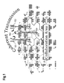
- shows a collaboration area comprising three base stations allowing for a coherent transmission towards associated mobile terminals;
- Fig.2
- depicts an schematic diagram visualizing an approach for feedback pre-selection at each of two mobile terminals;
- Fig.3
- shows a schematic diagram that illustrates a transforming of a MIMO channel into an effective MISO channel with known SINR.
- The approach provided proposes a collaborative antenna scheme for active interference management inside a so-called collaboration area (CA). It is in particular suggested utilizing a unified framework for feedback given by mobile terminals (MTs) for active interference management.
- Receive antennas at a mobile terminal can be used jointly for data detection as well as interference suppression. Each user may apply for one data stream. However, it is also an option to support multiple data streams per user. In such case, the mobile terminals may provide multiple MISO feedback channels.
- Considering the case of multiple Rx antennas per terminal, each user may independently select its preferred receive strategy (i.e. select Rx antenna(s), select MRC and/or IRC and utilize receive filter accordingly) and convey the effective MISO channel apparent behind the receive filter. The scenario of a single Rx antenna terminal corresponds to the Rx antenna selection.
- Each mobile terminal then determines the channel coefficients and then reports them to the serving base station (BS). In turn the BS distributes these then among the BS within the CA. The BSs then perform a joint pre-coder calculation in a parallel manner, reducing additional exchange of pre-coder weights and minimizing delay over the connecting link between BSs. A final coordinated and joint application of these pre-coder weights allows suppression of intra-cell interference and coherent joint transmission of data-streams from distributed antennas.
- The approach suggested applies in particular for systems using CSI-based pre-coding and/or beamforming irrespective of whether or not base station sectors are collaborating.
- For example, a framework for feedback provisioning from at least one mobile terminal to at least one base station is considered. The solution provided in particular utilizes an MISO channel and each mobile terminal may select a receive strategy independently from any other mobile terminal. Such selection can be conducted based on the computational capability of the respective mobile terminal.
- A multi-cell channel information may be fed back to at least one base station after receiver processing by the mobile terminal. Several base stations can be combined to a collaboration area (CA). Distributed processing can be provided by each base station thereby facilitating a real-time implementation.
-
Fig.1 shows a collaboration area comprising threebase stations -
Fig.2 depicts an schematic diagram visualizing a method for feedback pre-selection at each mobile terminal. - A
mobile terminal 201 comprises twoantennas 1 to a base station BS 1. Accordingly, amobile terminal 202 comprises twoantennas 2 to a base station BS 2. - The base stations BS 1 and BS 2 both perform a coherent
joint transmission 207 processing the whole pre-coder C CA1 on the given user feedback, but using the corresponding respective parts

Fig.2 comprises twoantennas Fig.2 communicate via aradio channel 212 described as H i C i indicating a collaborative area i. - In this case each sector is allowed to use independent unitary beamformers C 1, C 2 in case of non-collaborative transmission. Thus, each MT provides feedback on its effective MISO channel, seen among several BS antennas.
- It is noted that BS collaboration increases the number of antennas from the perspective of signal processing. For the case of multi-antenna MTs SDMA with a single data stream per user may be the dominant transmission mode in multi-user systems. Thus, providing feedback via a single data stream may suffice for a user and will save a significant amount of feedback overhead.
- In case of single-antenna MTs, each MT may process a MISO channel and may provide feedback information about thereof to its serving BS.
- In case of multi-antenna MTs, each MT may use linear receive filters to report an effective MISO to its serving base station. The effective MISO channel may be determined based on several input signals from one BS or several BSs. Each BS may provide several input signals via several antennas. Furthermore, the BSs may be of one CA, but can also be of different CAs. In particular a reference signal from a BS that is not part of the current CA can be utilized for beam forming purposes at the MT.
-
Fig.3 shows a schematic diagram that illustrates a transforming of a MIMO channel into an effective MISO channel with known SINR. Said effective MISO channel is conveyed as feedback information to the MT's serving BS. Hence, the MIMO channel

- Therefore each MT may choose at least one of the following approaches, in particular its receive filter(s), according to its own computational capabilities:
- Simple receive antenna selection;
- Maximum Ratio Combining (MRC);
- Interference Rejection Combining (IRC), in particular comprising different degrees of interference knowledge;
- Singular value decomposition (SVD), optionally in combination with MRC and/or IRC.
- Each BS in the collaborative area (CA) may use a pre-selected algorithm for user orthogonalization purposes and may be able to determine pre-coding weights in a distributed way.
- The following signalization mechanisms may be utilized:
- (a) The BSs may ask MTs to provide a specific type of CSI feedback, i.e. full MIMO-CSI or effective MISO-CSI.
- (b) Unique identifiers can be used for distributed processing, i.e. according to an order of BS antennas.
- (c) Protocols for stable joint transmission are preferably to ensure stable operation, e.g., in case of packet loss.
-
- (a) The approach enables a unified framework for feedback and also allows for non-collaborative transmission.
- (b) A distributed collaborative interference management is provided, including in particular network MIMO (cooperative multipoint transmission (CoMP), joint transmission).
- (c) An extent of collaboration can be selected at the BS.
- (d) An amount of feedback signaling can be significantly reduced for the transmission antennas of the base station(s) as well as for the receiving antennas of the mobile terminal. For example, in case of ra=2 receive antennas by a factor of 2 and in general by a factor of ra amounting to the number of receive antennas.
- Hereinafter, further details regarding the suggested concepts are described.
- A downlink multiple-input multiple-output (MIMO)-OFDM transmission system for an isolated sector with NT transmit and NR receive antennas per MT can be described on a per sub-carrier basis as follows

where - H
- is a NR × NT channel matrix;
- C
- is a unitary NT × NT pre-coding matrix or a matrix denoting any modulation format, in particular comprising amplitude modulation;
- x
- denotes a NT × 1 vector of transmit symbols;
- y, n
- denote NR × 1 vectors of received signals and of the additive white Gaussian noise (AWGN) samples, respectively, with a covariance amounting to E{nn H } = σ2I.
- In a downlink channel of a cellular system, frequency resources may be reused in all neighboring cells. Depending on the deployment of base station sites and depending on an actual position of the MT, the MT may receive interfering signals destined for other users in addition to its own desired signal.
- At an initial step, all BSs may provide Ω fixed unitary beam sets C ω, ω∈ {1, ..., Ω}.
- Each beam set may comprise αNT fixed pre-coding vectors (beams) b ω,u with u∈ {1, ..., αNT}, where α denotes a size of a collaboration area (CA). Each BS-cluster i may independently select one of these beam sets.
- Each sector may use NT beams, denoted by b i,u as the u-th pre-coding vector used by cluster i. The received downlink signal y m at the mobile terminal m in the cellular environment may amount to

- The desired data stream xi,u transmitted on the u-th beam from the i-th cluster is distorted by the intra-cluster and inter-cluster interference aggregated in ζi,u and z i,u, respectively.

- The αNT beams in the beam set C i may simultaneously be active, wherein an available power pi is assumed to be uniformly distributed over the αNT beams.
- Hence, the following applies:


with ps being a transmit power per sector. - A chosen set of pre-coders may be kept fixed, e.g., to

where C 1 is defined for NT=2 transmit antennas (Tx antennas) per sector. - A cluster of BS antennas may be grouped for joint signal pre-processing and a coherent transmission of data signals and a cooperation area (CA) may be defined. The CA may manage interference by utilizing joint signal processing prior to transmission over the wireless channel. Data signals coming from outside this CA will be treated as inter-cluster interference, where the spatial structure can be measured, e.g., by estimation of the interference co-variance matrix. CAs can be selected network-centric or user-centric. The user-centric choice can be determined, e.g., by measuring broadband channels to nearby BSs and by reporting a set of strongest BS antennas to the MT's serving BS. The serving BS may initialize the setup of a new CA or allocate this particular MT into a user group served inside a predefined CA. The overlap of CAs including different BS antenna combinations can be separated, e.g., in a frequency domain by means of resource partitioning.
- For downlink cooperation among a selected set of α cooperating BS sectors, a collaborative pre-coder C CA
1 can be modified to any kind of beamforming as shown inFig.2 . - Each collaborating BS in the CA determines in a distributed manner the whole pre-coder C CA
1 on the given user feedback utilizing the corresponding respective parts

-
Fig.2 shows a pre-coding for coherent joint transmission that is determined in a distributed fashion by two base stations, wherein the corresponding parts thereof are provided by each of the collaborating BSs. - For channel adaptive transmission to one MT or to several MTs, each MT may provide limited or full CSI to the BSs. With a limited amount of uplink resources, especially due to limited power supply at the MTs, CSI feedback overhead may advantageously be decreased saving valuable uplink resources. Therefore, a MT-assisted channel pre-processing is suggested.
- Transmitting a single stream to each of the multiple MTs in the cell allocates a significant portion of the system's capacity. Hence, a multi-user MIMO (MU-MIMO) transmission mode may advantageously be utilized.
- For NR > 1 a spatial degree of freedom at the MT' s receiver side can be utilized for the purpose of interference rejection combining (IRC) according to

where Z u is a covariance matrix of interfering signals aggregated in ζ i,u and z i,u, i.e.
with E[.] being an expectation operator. - An interference-aware MMSE receiver is given according to

wherein R yy denotes the covariance matrix of the received signal y m, i.e.
- It is noted that the MMSE receiver may be aware of interference either by having a full knowledge, i.e. spatial structure, or a partial knowledge, i.e. a power on the inter-cluster interference may be considered.
- The MMSE receiver may yield a post-equalization SINR as follows:

- All proposed schemes have in common that each MT can choose its desired receive strategy independently from any other MT according to its computational capabilities and knowledge on channel state information at the receiver (CSIR) including interference. Agreed assumptions between the MTs and the CA may be based on the fact that a minimum intra-cluster interference pre-coder is applied. The performance of different linear receivers to obtain an effective channel can be different after zero-forcing (ZF) pre-coding at the BSs.
- With regard to an example providing NR = 2 receive antennas (RX antennas) per MT, the principle can be illustrated as follows: Each MT pre-computes an effective multiple-input-single-output (MISO) channel and reports this to the serving BS in the cooperation area. Receiving such feedback from several users in the cooperation area, the BS may use different methods for user orthogonalization, e.g., linear pre-coding as ZF, MMSE or block diagoninalization (BD) or non-linear Tomlinson-Harashima pre-coding (THP).
- For baseline systems, the MT has only a single Rx antenna and therefore reports the true MISO channel to the BS according to:

h BST = H BS1 b BS1 J is a vector comprising j complex valued effective channel coefficients between Tx antennas from a first base station BS1 and the single Rx antenna of the first mobile terminal MT1. - According to this concept, the MISO channel h MT
m received at the m-th MT can be fed back to the base station in addition a SINR value. - The MT may not have any possibility to compensate inter-cluster interference, which limits the SINR. For the achievable SINR, the CA may provide the data stream to a particular MTm, while all other data streams used for residual MTs are orthogonalized by use of the ZF pre-coder. Thus, the MTs in the cluster do not experience any intra-cluster interference.

where
βMTm is a transmit power scaling factor applied on the data stream send to the m-th MT;

- It is noted that if no transmit power limit is applied, β MT
1 equals 1. The entire path-loss is pre-compensated at the transmitter, resulting in unit signal power at the receive antenna. - It is also noted that sectors may operate independently from one another while inter-cell interference is accounted for at the multi-antenna MT.
- Each BS may provide a fixed matrix C comprising unitary DFT beams. Assuming that the inter-cell interference is completely known at each MT, the MTs evaluate the achievable rate per beam and convey this information to their serving BS. At the BS, the feedback from different MTs is collected, and the DFT beams from the matrix C are assigned individually to the MT.
- The MTs are assumed to provide their preferred matrix index (PMI) and the corresponding SINR.
- It is an advantage that with the fixed beam set C used for the BSs, a co-channel interference (CCI) amounting to

becomes predictable, enabling an interference-aware scheduling in a cellular system. In combination with fair, interference-aware scheduling policies, users may benefit from almost doubled spectral efficiencies in the MIMO 2 × 2 system compared to the SISO setup. - In the following, the MTs considered are equipped with multiple Rx antennas for the purpose of IRC. The BSs are assumed to provide NT data streams to NT MTs.
- In this case, the MTs may use linear receive filters to transform the MIMO channel into an effective MISO channel, according to
Fig.3 . - The MT may provide feedback regarding an achievable SINR and the effective MISO channel h MT
m . - Furthermore, if true ZF pre-coding is assumed at the BSs, feedback can be split into amplitude and phase instead of I and Q samples to describe the channel. Hence, the amplitude may be of less importance and can be reduced to a mean path-loss. On the other hand, the phase information is useful to allow for an adequate ZF pre-coding.
- DFT-based pre-coding may be maintained, but the effective MISO channel may be fed back to the BS, which can be determined behind a linear equalizer at each MT. Thus, each MT may calculate a spatial receive vector for the best transmit stream and reports the product of receive filter according to equation (5) and the aggregated channel matrix from the cluster:

- A linear receive filter

- This approach may profit from a pre-selection of suitable resources. Further, gains from IRC are kept in the system. In addition, the MT is not required to have high computational power, e.g., to do a singular value decomposition (SVD) on the measured collaborative channel H i.
- With a fixed set M of users, which may be served in a resource block (RB), each user m decomposes its NR × αNT channel matrix


- Each MT may apply for a single data stream only, i.e. for a single MU-MIMO service. Thus, a dominant eigenmode can be selected, i.e. the eigenvector corresponding to the highest eigenvalue. The effective channel after maximum ratio combining (MRC) equalization using the dominant left eigenvector is given by

- This scheme advantageously maximizes the signal power transferred from collaborative BSs to the MT. The MTs may preferably be grouped such that their eigenmodes show a high orthogonality, in particular the highest possible orthogonality. This allows for an efficient power reduction.
- This solution combines the preceding two concepts, i.e. dominant eigenmode pre-coder with a MMSE equalization at the MT. Thus, a reporting based on the effective MISO channel h MT
m behind linear receive filter is assumed to be provided by the MT as follows:
- The linear receive filter is determined based on an assumption of eigenmode pre-coding for the dedicated data stream and DFT-based pre-coding for inter-cluster signals.
- Other data streams inside the cooperating cluster are assumed to be transmitted orthogonal in space.

- The initial spatial channel assumption concentrates on outside interference as the limiting interference contribution, while the effective MISO channel inside the cooperation area is chosen such that the desired signal from the set of BSs to the MT is maximized.
- The final SINR can thus be fully pre-computed at the BS, since the initial SINR reported from the MT under ideal pre-coding using the dominant eigenbeam forming (DEBF) will be altered by the power normalization per transmission stream only.
- Single-cell transmission may be based on fixed pre-coding matrices C i = C ω , where i identifies the base station.
- To enable IRC at the MT, the true multi-cell channel H i from (all) BSs to a given terminal m may be estimated. Pre-coding matrices may not change frequently in order to keep multi-cell interference predictable. Hence, a first channel estimation based on multi-cell pilot symbols is required at this step to determine H i C i .
- In order to estimate the effective MISO channel at the output of each linear receive filter, h MT
m may be determined as set forth above. Also, pilot symbols may be processed like data by the receive filter. Hence, the effective MISO channel can directly be estimated on such a common reference signal. - As in particular discussed above, reporting a virtual MISO channel is of advantage and can be orthogonalized by the collaborative BSs like a single antenna receiver. Once MTs are grouped and assigned to a CA, the pre-coder and its power normalization are determined by the used algorithm, which may preferably be the same on all distributed processing units. It may be of advantage in case the same software and/or hardware is utilized on all processing units of a CA.
- Each MT in the active set of users on a single data stream may be served while the Rx antennas are used for IRC purposes.
- A maximum number of αNT MISO channels experienced from different MTs are composed to form a compound virtual MIMO channel of a size NT × NT. A compound channel matrix can be orthogonalized by any linear or non-linear pre-coding technique, if a full rank is assured. This may be the case in a multi-point to multi-point channel. The proposed approach allows to benefit from two major advantages: First, the multiple receive antennas are efficiently used for suppression of external interference at the MT's side. Second, by reducing the number of data streams per MT, the degrees of freedom in multi-user grouping can be utilized such that the number of all active data streams is smaller than or equal to the number of active transmit antennas.
- After the BS has received the multi-casted CSI from the other BSs of the CA, a cross-check of all contents, in particular regarding the origin (MT and BS identifier) and a time stamp (frame number and optionally sub-frame number) is conducted. Next, all valid CSI data can be loaded in a pre-determined order, assuring that the compound channel matrices put together at different BSs are identical in each entry. This can be assured per sub-carrier or per physical RB in OFDM systems where transmit collaboration is applied.
- The pre-determined order can be achieved by numbering all active BS Tx antennas within the CA while keeping track of the corresponding MT identifier. This antenna numbering is advantageously known to all MTs.
- In case the compound channel matrix is available and valid, all processing units can use the same deterministic algorithms to determine the joint pre-coder C CA
1 . - As a final hand-shake before calculating the joint pre-coding matrix C CA
1 , the (in particular all) BSs distribute via multi-cast a correctly received CSI message to the (in particular to all) BSs of the CA. - If one BS has incomplete data, e.g., due to packet loss, other BSs within the CA can provide the missing pre-coder weights and the calculation of the post-detected SINR. This ensures that joint spatial pre-processing can still successfully be performed.
- It is noted that several protocols, e.g., master-slave or central controller approaches, can be utilized, but may inflict additional traffic and latency on the X2 interface for pre-coder and modulation and coding scheme (MCS) level exchange. This allows for data consistency at all distributed points, which is an important issue whenever a distributed approach is considered.
- The rationale of stringent transmit power constraints per transmit antenna and per site is based on
- operating the power amplifier at the BS at an optimum operation point with respect to a high Peak-to-Average-Power-Ratio of the OFDM time domain signal and
- keeping the emitted power spectral density flat, which is favorable for reliable broadband channel measurements and for spectrally balanced interference to other cells.
- In order to meet the requirements of a fixed maximum transmit power per Tx antenna, the pre-coder matrix is column-wise normalized such that the average transmitted power per data stream is (substantially) constant. On the average and considering slightly different phases and amplitudes over the entire frequency range of the OFDM symbol, a rather constant transmit power per Tx antenna can be reached as well. Since the normalization for all elements of one and the same pre-coder column is the same, the resulting SNRs post-detected per data stream can be normalized differently.
- According to the pre-determined order of the BS antennas, each BS knows which row out of the finally calculated joint pre-coder matrix belongs to its own transmit antennas. This particular row is selected and stored for further processing together with the user data which are expected for each user to arrive via multi-cast messaging on the X2 interface.
- The time stamp allows for a synchronization of pre-coder and data content, which is beneficial for successful coherent transmission of data and active interference management within the CA.
- In addition to CSI per sub-carrier or per resource block (RB), each MT reports the effective post-equalization SINR. The final SINR can be determined or predicted after ZF pre-coding applying the pre-chosen receive filter per MT.
- The normalization factors βMTm for the m-th column of the spatial pre-coder and therefore for the data stream to the m-th MT can be calculated and multiplied with the reported SINR per MT.
- The calculation of the final post-detection SINR considering joint transmit pre-coding and the reported effective SINR from each MT can again be calculated in a distributed fashion by the serving BS of each MT. This BS is in charge of the current and future continuation of higher layer protocols, such as HARQ. After having decided the final effective post-detect SINR to be expected at the MT for the allocated stream, a MCS level, a puncturing and a PDU size can be chosen such that each spatial layer is utilized for data transmission purposes.
- It is noted that puncturing is a method that allows reducing a forward error correction code for a first transmission. In case the first transmission is successful, the overhead portion based on such forward error correction code can be reduced thereby increasing the bandwidth to be utilized for user data. In case the first transmission with such reduced amount of forward error correction code is not successful, additional redundancy information is conveyed in a second transmission. Such shortening of the redundancy information (here: the forward error correction code) in the first transmission is referred to as "puncturing". The whole method can be referred to as hybrid ARQ.
- The chosen MCS level for each spatial layer is tagged to an associated encoded data stream and is again multi-casted to each BS belonging to the active set of antennas in the CA, which will perform mapping onto higher modulation formats locally and the mapping to the correct spatial pre-coder input queue.
- The MTs may in parallel be informed about the allocated resources and the MCS levels. Since resource allocation announcement is in charge of the serving BS for each MT, this can either be done in a cooperative transmit mode or in a non-cooperative mode per BS.
- Having established CAs and having found a suitable user group, the joint MIMO channel between the BS and the MT antennas can be treated as a standard point-to-multi-point MIMO channel.
- Thus, the spatial signal separation is performed at the BS antennas based on the known CSI. By exploiting this channel, adaptive spatial pre-coding the interference inside the CA can be reduced and - in a best-case scenario - an intra-cluster interference-free transmission may be achieved.
- Since collaborative signal processing across the network is most likely not feasible (in case of a huge network), it may be a solution to focus on a size for the CA to comprise 3 to 4 BS sectors. The residual inter-cluster interference may limit the performance of the CA. Thus, it can be focused on a joint SINR maximization including the spatial structure of the inter-cluster interference.
- To mitigate intra-cluster interference spatial ZF pre-coding can be considered, which is adapted to the joint channel H by choosing the pre-coder according to the Moor-Penrose pseudo-inverse of the channel

- This eliminates the inter-cluster interference.

which is equivalent to parallel AWGN transmission of data streams to different MTs. - To obtain the pre-coding vector for the m-th user, each BS in the CA aggregates the interfering MISO channels

according to the BD approach. This results in a matrix of a dimension (αNT - 1) × αNT
- Performing the singular value decomposition (SVD) of h MT
m results in
where
m . - It is noted that the null space can be represented by a matrix of a dimension λ × αNT . In case each user is served on its dominant eigenmode only, i.e. λ = 1,

-
- 3G-LTE
- 3G Long Term Evolution
- 3GPP
- 3rd generation partnership project
- ACK
- acknowledgement
- ARQ
- automatic repeat request
- AWGN
- additive white Gaussian noise
- BC
- broadcast channel
- BD
- block diagonalization
- BER
- bit error rate
- BS
- base station
- CA
- collaboration area
- CCI
- co-channel interference
- CDMA
- code-division multiple access
- CoMP
- cooperative multipoint transmission
- CSI
- channel state information
- CSIR
- channel state information at the receiver
- DEBF
- dominant eigenbeam forming
- DFT
- discrete Fourier transform
- FDD
- frequency division duplex
- FDMA
- frequency-division multiple access
- FEC
- forward error correction
- FSK
- frequency shift keying
- HARQ
- hybrid automatic repeat request
- IR
- incremental redundancy
- IRC
- interference rejection combining
- JT
- joint transmission
- MAC
- MAC layer, medium access control layer
- MCS
- modulation and coding scheme
- MIMO
- multiple-input multiple-output
- MISO
- multiple-input single-output
- MMSE
- minimum mean square error
- MRC
- maximum ratio combining
- MS
- multi-stream
- MSE
- mean square error
- MSHARQ
- MIMO single HARQ
- MT
- mobile terminal
- MU-MIMO
- multi-user MIMO
- MU-MUX
- multi-user spatial multiplexing
- MU-SDMA
- multi-user space-division multiple access
- NACK
- not acknowledgement
- OFDM
- orthogonal frequency division multiplexing
- OFDMA
- orthogonal frequency division multiple access
- probability density function
- PDU
- protocol data unit
- PHY
- PHY layer, physical layer
- PMI
- preferred matrix index
- QAM
- quadrature amplitude modulation
- RB
- resource block
- Rx
- receiver
- SDIV
- spatial diversity
- SDMA
- space-division multiple access
- SIMO
- single-input multiple-output
- SINR
- signal to interference and noise ratio
- SIR
- signal to interference ratio
- SISO
- single-input single-output
- SMUX
- spatial multiplexing
- SNR
- signal to noise ratio
- SU-MIMO
- single-user MIMO
- SU-MUX
- single-user spatial multiplexing
- SVD
- singular value decomposition
- TDD
- time division duplex
- TDMA
- time division multiple access
- THP
- Tomlinson-Harashima pre-coding
- Tx
- transmitter
- UE
- user equipment
- UMTS
- Universal Mobile Telecommunications System
- WiMAX
- Worldwide Interoperability for Microwave Access
- ZF
- zero forcing
Claims (11)
- A method for data processing by a mobile terminal (201, 202) comprising several antennas (203, 204, 205, 206) in a communication network comprising multiple base stations (101, 102, 103, BS1, BS2) organized as a collaboration area in particular providing a coherent transmission, comprising the steps of:- the mobile terminal (201, 202), receives several input signals from at least one base station (BS1, BS2);- the mobile terminal (201, 202) selects a preferred receive strategy independently from other mobile terminals (201, 202) in the communication network, and- processes said several input signals into feedback information that is conveyed to the mobile terminal's serving base station in the collaboration area (BS1, BS2) characterized in that the feedback information conveyed is an effective multiple-input single-output channel determined from the processed several input signals.
- The method according to claim 1, wherein the mobile terminal, uses at least one antenna for interference suppression purposes.
- The method according to claim 1,- wherein the base station (BS1, BS2) distributes the feedback information to at least one further base station and/or to a central unit,- wherein the base station (BS1, BS2) and the at least one further base station and/or the central unit aware of the feedback information perform a joint processing, in particular a pre-coder calculation.
- The method according to any of claims 1 or 3, wherein the feedback information comprises a virtual pre-coding conducted by the mobile terminal.
- The method according to any of the preceding claims, wherein the input signal is a reference signal conveyed via several antennas of the at least one base station (BS1, BS2).
- The method according to any of the preceding claims, wherein the at least one base station (BS1, BS2) conducts pre-coding and/or beamforming based on the feedback information obtained by the mobile terminal (201, 202).
- The method according to any of the preceding claims, wherein the at least one base station (BS1, BS2) conveys a first type of input signals with a first amount of information less often than a conveyed second type of input signals with a second amount of information, the second amount of information being smaller than the first amount of information.
- The method according to any of the preceding claims, wherein the feedback information comprises a first type of feedback information with a first amount of information conveyed less often than a conveyed second type of feedback information with a second amount of information, the second amount of information being smaller than the first amount of information.
- The method according to claim 1, wherein the base stations (BS1, BS2) of a collaboration area provide distributed processing.
- The method according to any of the preceding claims, wherein the input signals from the at least one base station (BS1, BS2) are orthogonal to one another.
- A device (201, 202) comprising a processor unit that is arranged to execute the method according to claims 1 to 10.
Priority Applications (1)
| Application Number | Priority Date | Filing Date | Title |
|---|---|---|---|
| EP10713934.7A EP2420005B1 (en) | 2009-04-14 | 2010-04-14 | Method and device for data processing in a communication network |
Applications Claiming Priority (3)
| Application Number | Priority Date | Filing Date | Title |
|---|---|---|---|
| EP09100235.2A EP2242187B1 (en) | 2009-04-14 | 2009-04-14 | Method and device for data processing in a communication network |
| PCT/EP2010/054853 WO2010119044A1 (en) | 2009-04-14 | 2010-04-14 | Method and device for data processing in a communication network |
| EP10713934.7A EP2420005B1 (en) | 2009-04-14 | 2010-04-14 | Method and device for data processing in a communication network |
Publications (2)
| Publication Number | Publication Date |
|---|---|
| EP2420005A1 EP2420005A1 (en) | 2012-02-22 |
| EP2420005B1 true EP2420005B1 (en) | 2015-09-16 |
Family
ID=40723155
Family Applications (2)
| Application Number | Title | Priority Date | Filing Date |
|---|---|---|---|
| EP09100235.2A Active EP2242187B1 (en) | 2009-04-14 | 2009-04-14 | Method and device for data processing in a communication network |
| EP10713934.7A Active EP2420005B1 (en) | 2009-04-14 | 2010-04-14 | Method and device for data processing in a communication network |
Family Applications Before (1)
| Application Number | Title | Priority Date | Filing Date |
|---|---|---|---|
| EP09100235.2A Active EP2242187B1 (en) | 2009-04-14 | 2009-04-14 | Method and device for data processing in a communication network |
Country Status (4)
| Country | Link |
|---|---|
| US (1) | US9800297B2 (en) |
| EP (2) | EP2242187B1 (en) |
| ES (1) | ES2557894T3 (en) |
| WO (1) | WO2010119044A1 (en) |
Families Citing this family (33)
| Publication number | Priority date | Publication date | Assignee | Title |
|---|---|---|---|---|
| ES2557894T3 (en) * | 2009-04-14 | 2016-01-29 | Fraunhofer-Gesellschaft zur Förderung der angewandten Forschung e.V. | Method and device for data processing in a communication network |
| US8934557B2 (en) * | 2010-06-30 | 2015-01-13 | Telefonaktiebolaget L M Ericsson (Publ) | Statistical joint precoding in multi-cell, multi-user MIMO |
| CN102457319B (en) * | 2010-10-28 | 2014-04-09 | 中兴通讯股份有限公司 | Business data distribution method and device |
| EP2679058B1 (en) | 2011-02-24 | 2017-09-13 | Nokia Solutions and Networks Oy | Configuring power distribution within cooperation areas of cellular communication networks |
| CN102857277B (en) * | 2011-06-29 | 2017-05-10 | 夏普株式会社 | Channel state information feedback method and user device |
| CN102983935B (en) * | 2011-09-07 | 2017-10-27 | 株式会社Ntt都科摩 | Precoding, pre-coding/pre-decoding method and emitter and mobile terminal based on interference alignment |
| KR101974900B1 (en) | 2012-01-19 | 2019-05-07 | 삼성전자주식회사 | Method and apparatus for hybrid automatic retransmit request in a communication system based a mobile centric virtual cell |
| JP5908307B2 (en) * | 2012-03-06 | 2016-04-26 | シャープ株式会社 | Precoding device, wireless transmission device, wireless reception device, wireless communication system, and integrated circuit |
| EP2642706B1 (en) * | 2012-03-21 | 2017-10-04 | Telefonaktiebolaget LM Ericsson (publ) | Methods and devices for estimating channel quality |
| CN103378883B (en) * | 2012-04-19 | 2016-09-28 | 电信科学技术研究院 | Frequency-domain equilibrium method under the conditions of a kind of up MU-MIMO and device |
| US8781027B2 (en) | 2012-05-10 | 2014-07-15 | Intel Mobile Communications GmbH | Apparatus and method for determining a precoding matrix |
| US8842782B2 (en) * | 2012-05-10 | 2014-09-23 | Intel Mobile Communications GmbH | Apparatus and method for decoding a received signal |
| WO2014021633A1 (en) * | 2012-07-31 | 2014-02-06 | 삼성전자 주식회사 | Communication method and device using beamforming in wireless communication system |
| WO2014088271A1 (en) * | 2012-12-09 | 2014-06-12 | 엘지전자 주식회사 | Method and device for transmitting and receiving signal in multi-cell cooperative communication system |
| CN103945555B (en) * | 2013-01-21 | 2018-03-20 | 电信科学技术研究院 | Resource regulating method and equipment under coordinated multipoint transmission |
| US9654272B2 (en) * | 2013-03-08 | 2017-05-16 | Electronics & Telecommunications Research Institute | Method for multi-input multi-output communication in large-scale antenna system |
| KR102197717B1 (en) * | 2013-03-08 | 2020-12-31 | 한국전자통신연구원 | Method for multi-input multi-output communication in large-scale antenna system |
| EP3039834B1 (en) * | 2013-08-30 | 2018-10-24 | FRAUNHOFER-GESELLSCHAFT zur Förderung der angewandten Forschung e.V. | Method and apparatus for transmitting a signal with constant envelope |
| US10420118B2 (en) * | 2013-09-27 | 2019-09-17 | Qualcomm Incorporated | Multiflow with antenna selection |
| US9526016B2 (en) | 2014-02-14 | 2016-12-20 | Samsung Electronics Co., Ltd. | Computing system with feedback mechanism and method of operation thereof |
| DE102015110066B3 (en) * | 2015-06-23 | 2016-07-21 | Intel IP Corporation | Method and device for determining channel state information |
| US10277428B2 (en) * | 2015-07-10 | 2019-04-30 | RF DSP Inc. | Methods for reducing complexity of pre-coding matrix computation and grouping of user equipments in massive MIMO systems |
| US10236958B2 (en) * | 2016-03-21 | 2019-03-19 | University Of Science And Technology Of China | Method for signal transmission to multiple user equipments utilizing reciprocity of wireless channel |
| GB2551476A (en) * | 2016-05-11 | 2017-12-27 | Nokia Solutions & Networks Oy | Method, system and apparatus |
| CN107733500B (en) * | 2016-08-11 | 2023-08-22 | 华为技术有限公司 | Channel state information measurement feedback method and device |
| US11115097B2 (en) * | 2017-02-02 | 2021-09-07 | Nokia Technologies Oy | Adaptive explicit CSI feedback and overhead reduction |
| EP3580879A4 (en) * | 2017-03-27 | 2020-08-19 | MediaTek Singapore Pte. Ltd. | Harq and arq design for urllc in mobile communications |
| US20230040058A1 (en) * | 2020-01-20 | 2023-02-09 | Qualcomm Incorporated | Channel state information feedback for multiple transmission reception points |
| US11943011B2 (en) | 2020-04-13 | 2024-03-26 | Sony Group Corporation | Wireless base station |
| DE112020007407B4 (en) * | 2020-09-17 | 2024-09-12 | Mitsubishi Electric Corporation | RADIO COMMUNICATION DEVICE, CONTROL CIRCUIT, STORAGE MEDIUM AND SIGNAL PROCESSING METHOD |
| KR102805538B1 (en) * | 2022-04-07 | 2025-05-12 | 한국전자통신연구원 | Beamforming Signal Transmitting and Receiving Method and Signal Transceiver for Implementing the Same |
| CN114629754B (en) * | 2022-05-13 | 2022-08-02 | 成都爱瑞无线科技有限公司 | Interference noise equalization method, system and storage medium |
| EP4283935A1 (en) * | 2022-05-27 | 2023-11-29 | Nokia Solutions and Networks Oy | Interference rejection combining with reduced complexity |
Family Cites Families (30)
| Publication number | Priority date | Publication date | Assignee | Title |
|---|---|---|---|---|
| CN1602614A (en) * | 2001-12-11 | 2005-03-30 | 皇家飞利浦电子股份有限公司 | System for transmitting additional information via a network |
| AU2003301004A1 (en) * | 2002-12-16 | 2004-07-22 | Matsushita Electric Industrial Co., Ltd. | Using multiple receive antennas to determine the location of a transmitter with respect to a receiver in ultra wideband systems |
| US7428268B2 (en) * | 2004-12-07 | 2008-09-23 | Adaptix, Inc. | Cooperative MIMO in multicell wireless networks |
| US7773961B2 (en) * | 2005-12-09 | 2010-08-10 | Samsung Electronics Co., Ltd. | Apparatus and method for channel estimation without signaling overhead |
| US7526036B2 (en) * | 2006-04-20 | 2009-04-28 | Mitsubishi Electric Research Laboratories, Inc. | System and method for transmitting signals in cooperative base station multi-user mimo networks |
| US8626104B2 (en) * | 2006-09-28 | 2014-01-07 | Apple Inc. | Generalized codebook design method for limited feedback systems |
| US20080139153A1 (en) * | 2006-12-12 | 2008-06-12 | Hong Kong Applied Science And Technology Research Institute Co., Ltd. | Antenna configuration selection using outdated channel state information |
| CN101682465B (en) * | 2007-05-07 | 2016-01-06 | 诺基亚公司 | For feedback and the link adaptation techniques of wireless network |
| JP5126224B2 (en) * | 2007-05-16 | 2013-01-23 | 富士通株式会社 | Wireless communication apparatus and wireless communication method |
| KR101173940B1 (en) * | 2007-06-01 | 2012-09-03 | 보드 오브 리전츠, 더 유니버시티 오브 텍사스 시스템 | Apparatus and method for transmission and recepetion in multi input multi output system with relay |
| US20090005102A1 (en) * | 2007-06-30 | 2009-01-01 | Suman Das | Method and Apparatus for Dynamically Adjusting Base Station Transmit Power |
| US7826853B2 (en) * | 2007-11-02 | 2010-11-02 | Mitsubishi Electric Research Laboratories, Inc. | Cooperative base stations in wireless networks |
| KR100991794B1 (en) * | 2007-12-31 | 2010-11-03 | 엘지전자 주식회사 | How to reduce intercell interference |
| CN104539343B (en) * | 2008-01-02 | 2019-01-04 | 交互数字技术公司 | WTRU, the method used in WTRU and network node |
| US8064849B2 (en) * | 2008-02-07 | 2011-11-22 | Telefonaktiebolaget Lm Ericsson (Publ) | Precoding for multiple anntennas |
| US20090225720A1 (en) * | 2008-03-10 | 2009-09-10 | Molisch Andreas F | Base Station Cooperation and Channel Estimation |
| US20090279478A1 (en) * | 2008-05-06 | 2009-11-12 | Motorola, Inc. | Method and apparatus for facilitating dynamic cooperative interference reduction |
| KR101486378B1 (en) * | 2008-05-07 | 2015-01-26 | 엘지전자 주식회사 | Methods of transmitting and receciving data in collative multiple input multiple output antenna mobile communication system |
| KR20100005649A (en) * | 2008-07-07 | 2010-01-15 | 엘지전자 주식회사 | A precoding method using multi-codebook |
| US8254318B2 (en) * | 2008-07-11 | 2012-08-28 | Alcatel Lucent | Wireless communication system and method of joint beamforming wireless communication |
| KR100964438B1 (en) * | 2008-12-19 | 2010-06-16 | 성균관대학교산학협력단 | Apparatus and method for flexible clustered multi-bs mimo service |
| EP2203015A1 (en) * | 2008-12-23 | 2010-06-30 | Nokia Siemens Networks OY | Method for generating cooperation areas in communications networks and corresponding network nodes |
| US8204470B2 (en) * | 2009-01-06 | 2012-06-19 | Texas Instruments Incorporated | Predecoding for joint processing coordinated multi-point transmission |
| CN102388541B (en) * | 2009-01-23 | 2014-08-06 | 诺基亚公司 | Interference suppression method and apparatus during device-to-device communications |
| US8687731B2 (en) * | 2009-02-02 | 2014-04-01 | Qualcomm Incorporated | Uplink open-loop spatial multiplexing in wireless communications |
| US9608703B2 (en) * | 2009-03-03 | 2017-03-28 | Monument Bank Of Intellectual Property, Llc | Closed loop MIMO harmonized feedback |
| KR101691824B1 (en) * | 2009-03-04 | 2017-01-02 | 엘지전자 주식회사 | Method and apparatus for configuring CoMP set in wireless communication system |
| US8369429B2 (en) * | 2009-03-18 | 2013-02-05 | Lg Electronics Inc. | Method and apparatus for transmitting precoding matrix index in a wireless communication system using CoMP scheme |
| ES2557894T3 (en) * | 2009-04-14 | 2016-01-29 | Fraunhofer-Gesellschaft zur Förderung der angewandten Forschung e.V. | Method and device for data processing in a communication network |
| WO2011023217A1 (en) * | 2009-08-24 | 2011-03-03 | Nokia Siemens Networks Oy | Controlling scheduling decisions in a distributed cooperation system |
-
2009
- 2009-04-14 ES ES09100235.2T patent/ES2557894T3/en active Active
- 2009-04-14 EP EP09100235.2A patent/EP2242187B1/en active Active
-
2010
- 2010-04-14 WO PCT/EP2010/054853 patent/WO2010119044A1/en not_active Ceased
- 2010-04-14 US US13/264,259 patent/US9800297B2/en active Active
- 2010-04-14 EP EP10713934.7A patent/EP2420005B1/en active Active
Also Published As
| Publication number | Publication date |
|---|---|
| ES2557894T3 (en) | 2016-01-29 |
| EP2242187B1 (en) | 2015-10-28 |
| US20120113897A1 (en) | 2012-05-10 |
| US9800297B2 (en) | 2017-10-24 |
| EP2242187A1 (en) | 2010-10-20 |
| WO2010119044A1 (en) | 2010-10-21 |
| EP2420005A1 (en) | 2012-02-22 |
Similar Documents
| Publication | Publication Date | Title |
|---|---|---|
| EP2420005B1 (en) | Method and device for data processing in a communication network | |
| CN102598525B (en) | Method and device for terminal to transmit feedback information in wireless communication system using CoMP transmission | |
| EP2227869B1 (en) | Method for reducing inter-cell interference | |
| US8218422B2 (en) | Coordinated linear beamforming in downlink multi-cell wireless networks | |
| EP2891260B1 (en) | Method and wireless terminal for mitigating downlink interference | |
| EP2237442B1 (en) | Method, system and transmitter for adaptive coordinated transmission in wireless communications | |
| EP2230807B1 (en) | Apparatus and method for reducing inter-cell interference in multiple input multiple output system | |
| CN101867462A (en) | A multi-base station cooperative linear precoding method based on the minimum total bit error rate | |
| EP2683093B1 (en) | Mobile terminal device, wireless base station and wireless communication method | |
| CN107683614B (en) | Method and apparatus for transmitting and receiving channel information in inter-vehicle communication system | |
| CN103220088A (en) | Method, terminal and base station for uplink interference cancellation | |
| CN103378894A (en) | Radio communications system and method performed therein | |
| EP2664080B1 (en) | Antenna weighting in relation to transmissions from two cells | |
| Kim et al. | Coordinated beamforming, interference-aware power control, and scheduling framework for 6G wireless networks | |
| CN110011706B (en) | Method and device for optimizing cooperative transmission | |
| CN103188006B (en) | A kind of downlink collaboration multipoint transmission method and system | |
| CN101621357B (en) | Mimo communication system and method thereof | |
| Badic et al. | Analysis of CQI prediction for MU-MIMO in LTE systems | |
| JP5777092B2 (en) | Wireless communication device, wireless transmission system, and wireless transmission method | |
| Thiele et al. | A unified feedback scheme for distributed interference management in cellular systems: Benefits and challenges for real-time implementation | |
| CN103312394B (en) | A kind of uplink interference processing method and system | |
| Pennanen et al. | System level evaluation of TDD based LTE-Advanced MIMO-OFDMA systems | |
| Li et al. | Enhanced limited rate implicit CSI feedback and its usage in covariance matrix based MU-MIMO | |
| Khan et al. | Zero-forcing beamforming with block diagonalization scheme for Coordinated Multi-Point transmission | |
| Thiele et al. | Cooperative multi-user MIMO based on limited feedback in downlink ofdm systems |
Legal Events
| Date | Code | Title | Description |
|---|---|---|---|
| PUAI | Public reference made under article 153(3) epc to a published international application that has entered the european phase |
Free format text: ORIGINAL CODE: 0009012 |
|
| 17P | Request for examination filed |
Effective date: 20111114 |
|
| AK | Designated contracting states |
Kind code of ref document: A1 Designated state(s): AT BE BG CH CY CZ DE DK EE ES FI FR GB GR HR HU IE IS IT LI LT LU LV MC MK MT NL NO PL PT RO SE SI SK SM TR |
|
| RIN1 | Information on inventor provided before grant (corrected) |
Inventor name: WIRTH, THOMAS Inventor name: ZIRWAS, WOLFGANG Inventor name: HAUSTEIN, THOMAS Inventor name: SCHELLMANN, MALTE Inventor name: JUNGNICKEL, VOLKER Inventor name: THIELE, LARS Inventor name: SCHULZ, EGON |
|
| DAX | Request for extension of the european patent (deleted) | ||
| 17Q | First examination report despatched |
Effective date: 20120727 |
|
| RAP1 | Party data changed (applicant data changed or rights of an application transferred) |
Owner name: FRAUNHOFER-GESELLSCHAFT ZUR FOERDERUNG DER ANGEWAN Owner name: NOKIA SOLUTIONS AND NETWORKS OY |
|
| GRAP | Despatch of communication of intention to grant a patent |
Free format text: ORIGINAL CODE: EPIDOSNIGR1 |
|
| INTG | Intention to grant announced |
Effective date: 20150508 |
|
| GRAS | Grant fee paid |
Free format text: ORIGINAL CODE: EPIDOSNIGR3 |
|
| GRAA | (expected) grant |
Free format text: ORIGINAL CODE: 0009210 |
|
| AK | Designated contracting states |
Kind code of ref document: B1 Designated state(s): AT BE BG CH CY CZ DE DK EE ES FI FR GB GR HR HU IE IS IT LI LT LU LV MC MK MT NL NO PL PT RO SE SI SK SM TR |
|
| REG | Reference to a national code |
Ref country code: GB Ref legal event code: FG4D |
|
| REG | Reference to a national code |
Ref country code: CH Ref legal event code: EP |
|
| REG | Reference to a national code |
Ref country code: IE Ref legal event code: FG4D |
|
| REG | Reference to a national code |
Ref country code: AT Ref legal event code: REF Ref document number: 750516 Country of ref document: AT Kind code of ref document: T Effective date: 20151015 |
|
| REG | Reference to a national code |
Ref country code: DE Ref legal event code: R096 Ref document number: 602010027552 Country of ref document: DE |
|
| REG | Reference to a national code |
Ref country code: NL Ref legal event code: MP Effective date: 20150916 |
|
| PG25 | Lapsed in a contracting state [announced via postgrant information from national office to epo] |
Ref country code: NO Free format text: LAPSE BECAUSE OF FAILURE TO SUBMIT A TRANSLATION OF THE DESCRIPTION OR TO PAY THE FEE WITHIN THE PRESCRIBED TIME-LIMIT Effective date: 20151216 Ref country code: LT Free format text: LAPSE BECAUSE OF FAILURE TO SUBMIT A TRANSLATION OF THE DESCRIPTION OR TO PAY THE FEE WITHIN THE PRESCRIBED TIME-LIMIT Effective date: 20150916 Ref country code: LV Free format text: LAPSE BECAUSE OF FAILURE TO SUBMIT A TRANSLATION OF THE DESCRIPTION OR TO PAY THE FEE WITHIN THE PRESCRIBED TIME-LIMIT Effective date: 20150916 Ref country code: GR Free format text: LAPSE BECAUSE OF FAILURE TO SUBMIT A TRANSLATION OF THE DESCRIPTION OR TO PAY THE FEE WITHIN THE PRESCRIBED TIME-LIMIT Effective date: 20151217 Ref country code: FI Free format text: LAPSE BECAUSE OF FAILURE TO SUBMIT A TRANSLATION OF THE DESCRIPTION OR TO PAY THE FEE WITHIN THE PRESCRIBED TIME-LIMIT Effective date: 20150916 |
|
| REG | Reference to a national code |
Ref country code: LT Ref legal event code: MG4D |
|
| REG | Reference to a national code |
Ref country code: AT Ref legal event code: MK05 Ref document number: 750516 Country of ref document: AT Kind code of ref document: T Effective date: 20150916 |
|
| PG25 | Lapsed in a contracting state [announced via postgrant information from national office to epo] |
Ref country code: SE Free format text: LAPSE BECAUSE OF FAILURE TO SUBMIT A TRANSLATION OF THE DESCRIPTION OR TO PAY THE FEE WITHIN THE PRESCRIBED TIME-LIMIT Effective date: 20150916 Ref country code: HR Free format text: LAPSE BECAUSE OF FAILURE TO SUBMIT A TRANSLATION OF THE DESCRIPTION OR TO PAY THE FEE WITHIN THE PRESCRIBED TIME-LIMIT Effective date: 20150916 |
|
| PG25 | Lapsed in a contracting state [announced via postgrant information from national office to epo] |
Ref country code: NL Free format text: LAPSE BECAUSE OF FAILURE TO SUBMIT A TRANSLATION OF THE DESCRIPTION OR TO PAY THE FEE WITHIN THE PRESCRIBED TIME-LIMIT Effective date: 20150916 |
|
| PG25 | Lapsed in a contracting state [announced via postgrant information from national office to epo] |
Ref country code: EE Free format text: LAPSE BECAUSE OF FAILURE TO SUBMIT A TRANSLATION OF THE DESCRIPTION OR TO PAY THE FEE WITHIN THE PRESCRIBED TIME-LIMIT Effective date: 20150916 Ref country code: ES Free format text: LAPSE BECAUSE OF FAILURE TO SUBMIT A TRANSLATION OF THE DESCRIPTION OR TO PAY THE FEE WITHIN THE PRESCRIBED TIME-LIMIT Effective date: 20150916 Ref country code: SK Free format text: LAPSE BECAUSE OF FAILURE TO SUBMIT A TRANSLATION OF THE DESCRIPTION OR TO PAY THE FEE WITHIN THE PRESCRIBED TIME-LIMIT Effective date: 20150916 Ref country code: IS Free format text: LAPSE BECAUSE OF FAILURE TO SUBMIT A TRANSLATION OF THE DESCRIPTION OR TO PAY THE FEE WITHIN THE PRESCRIBED TIME-LIMIT Effective date: 20160116 Ref country code: IT Free format text: LAPSE BECAUSE OF FAILURE TO SUBMIT A TRANSLATION OF THE DESCRIPTION OR TO PAY THE FEE WITHIN THE PRESCRIBED TIME-LIMIT Effective date: 20150916 Ref country code: CZ Free format text: LAPSE BECAUSE OF FAILURE TO SUBMIT A TRANSLATION OF THE DESCRIPTION OR TO PAY THE FEE WITHIN THE PRESCRIBED TIME-LIMIT Effective date: 20150916 |
|
| PG25 | Lapsed in a contracting state [announced via postgrant information from national office to epo] |
Ref country code: PL Free format text: LAPSE BECAUSE OF FAILURE TO SUBMIT A TRANSLATION OF THE DESCRIPTION OR TO PAY THE FEE WITHIN THE PRESCRIBED TIME-LIMIT Effective date: 20150916 Ref country code: RO Free format text: LAPSE BECAUSE OF FAILURE TO SUBMIT A TRANSLATION OF THE DESCRIPTION OR TO PAY THE FEE WITHIN THE PRESCRIBED TIME-LIMIT Effective date: 20150916 Ref country code: PT Free format text: LAPSE BECAUSE OF FAILURE TO SUBMIT A TRANSLATION OF THE DESCRIPTION OR TO PAY THE FEE WITHIN THE PRESCRIBED TIME-LIMIT Effective date: 20160118 Ref country code: AT Free format text: LAPSE BECAUSE OF FAILURE TO SUBMIT A TRANSLATION OF THE DESCRIPTION OR TO PAY THE FEE WITHIN THE PRESCRIBED TIME-LIMIT Effective date: 20150916 |
|
| REG | Reference to a national code |
Ref country code: DE Ref legal event code: R097 Ref document number: 602010027552 Country of ref document: DE |
|
| PLBE | No opposition filed within time limit |
Free format text: ORIGINAL CODE: 0009261 |
|
| STAA | Information on the status of an ep patent application or granted ep patent |
Free format text: STATUS: NO OPPOSITION FILED WITHIN TIME LIMIT |
|
| 26N | No opposition filed |
Effective date: 20160617 |
|
| PG25 | Lapsed in a contracting state [announced via postgrant information from national office to epo] |
Ref country code: DK Free format text: LAPSE BECAUSE OF FAILURE TO SUBMIT A TRANSLATION OF THE DESCRIPTION OR TO PAY THE FEE WITHIN THE PRESCRIBED TIME-LIMIT Effective date: 20150916 Ref country code: BE Free format text: LAPSE BECAUSE OF NON-PAYMENT OF DUE FEES Effective date: 20160430 |
|
| PG25 | Lapsed in a contracting state [announced via postgrant information from national office to epo] |
Ref country code: SI Free format text: LAPSE BECAUSE OF FAILURE TO SUBMIT A TRANSLATION OF THE DESCRIPTION OR TO PAY THE FEE WITHIN THE PRESCRIBED TIME-LIMIT Effective date: 20150916 |
|
| REG | Reference to a national code |
Ref country code: CH Ref legal event code: PL |
|
| PG25 | Lapsed in a contracting state [announced via postgrant information from national office to epo] |
Ref country code: BE Free format text: LAPSE BECAUSE OF FAILURE TO SUBMIT A TRANSLATION OF THE DESCRIPTION OR TO PAY THE FEE WITHIN THE PRESCRIBED TIME-LIMIT Effective date: 20150916 Ref country code: LU Free format text: LAPSE BECAUSE OF FAILURE TO SUBMIT A TRANSLATION OF THE DESCRIPTION OR TO PAY THE FEE WITHIN THE PRESCRIBED TIME-LIMIT Effective date: 20160414 |
|
| REG | Reference to a national code |
Ref country code: IE Ref legal event code: MM4A |
|
| REG | Reference to a national code |
Ref country code: FR Ref legal event code: ST Effective date: 20161230 |
|
| PG25 | Lapsed in a contracting state [announced via postgrant information from national office to epo] |
Ref country code: LI Free format text: LAPSE BECAUSE OF NON-PAYMENT OF DUE FEES Effective date: 20160430 Ref country code: FR Free format text: LAPSE BECAUSE OF NON-PAYMENT OF DUE FEES Effective date: 20160502 Ref country code: CH Free format text: LAPSE BECAUSE OF NON-PAYMENT OF DUE FEES Effective date: 20160430 |
|
| PG25 | Lapsed in a contracting state [announced via postgrant information from national office to epo] |
Ref country code: IE Free format text: LAPSE BECAUSE OF NON-PAYMENT OF DUE FEES Effective date: 20160414 |
|
| PG25 | Lapsed in a contracting state [announced via postgrant information from national office to epo] |
Ref country code: HU Free format text: LAPSE BECAUSE OF FAILURE TO SUBMIT A TRANSLATION OF THE DESCRIPTION OR TO PAY THE FEE WITHIN THE PRESCRIBED TIME-LIMIT; INVALID AB INITIO Effective date: 20100414 Ref country code: CY Free format text: LAPSE BECAUSE OF FAILURE TO SUBMIT A TRANSLATION OF THE DESCRIPTION OR TO PAY THE FEE WITHIN THE PRESCRIBED TIME-LIMIT Effective date: 20150916 Ref country code: SM Free format text: LAPSE BECAUSE OF FAILURE TO SUBMIT A TRANSLATION OF THE DESCRIPTION OR TO PAY THE FEE WITHIN THE PRESCRIBED TIME-LIMIT Effective date: 20150916 |
|
| PG25 | Lapsed in a contracting state [announced via postgrant information from national office to epo] |
Ref country code: TR Free format text: LAPSE BECAUSE OF FAILURE TO SUBMIT A TRANSLATION OF THE DESCRIPTION OR TO PAY THE FEE WITHIN THE PRESCRIBED TIME-LIMIT Effective date: 20150916 Ref country code: MK Free format text: LAPSE BECAUSE OF FAILURE TO SUBMIT A TRANSLATION OF THE DESCRIPTION OR TO PAY THE FEE WITHIN THE PRESCRIBED TIME-LIMIT Effective date: 20150916 Ref country code: MT Free format text: LAPSE BECAUSE OF NON-PAYMENT OF DUE FEES Effective date: 20160430 Ref country code: MC Free format text: LAPSE BECAUSE OF FAILURE TO SUBMIT A TRANSLATION OF THE DESCRIPTION OR TO PAY THE FEE WITHIN THE PRESCRIBED TIME-LIMIT Effective date: 20150916 |
|
| PG25 | Lapsed in a contracting state [announced via postgrant information from national office to epo] |
Ref country code: BG Free format text: LAPSE BECAUSE OF FAILURE TO SUBMIT A TRANSLATION OF THE DESCRIPTION OR TO PAY THE FEE WITHIN THE PRESCRIBED TIME-LIMIT Effective date: 20150916 |
|
| REG | Reference to a national code |
Ref country code: DE Ref legal event code: R081 Ref document number: 602010027552 Country of ref document: DE Owner name: NOKIA TECHNOLOGIES OY, FI Free format text: FORMER OWNERS: FRAUNHOFER-GESELLSCHAFT ZUR FOERDERUNG DER ANGEWANDTEN FORSCHUNG EINGETRAGENER VEREIN, 80686 MUENCHEN, DE; NOKIA SOLUTIONS AND NETWORKS OY, ESPOO, FI Ref country code: DE Ref legal event code: R081 Ref document number: 602010027552 Country of ref document: DE Owner name: FRAUNHOFER-GESELLSCHAFT ZUR FOERDERUNG DER ANG, DE Free format text: FORMER OWNERS: FRAUNHOFER-GESELLSCHAFT ZUR FOERDERUNG DER ANGEWANDTEN FORSCHUNG EINGETRAGENER VEREIN, 80686 MUENCHEN, DE; NOKIA SOLUTIONS AND NETWORKS OY, ESPOO, FI |
|
| REG | Reference to a national code |
Ref country code: DE Ref legal event code: R081 Ref document number: 602010027552 Country of ref document: DE Owner name: FRAUNHOFER-GESELLSCHAFT ZUR FOERDERUNG DER ANG, DE Free format text: FORMER OWNERS: FRAUNHOFER-GESELLSCHAFT ZUR FOERDERUNG DER ANGEWANDTEN FORSCHUNG EINGETRAGENER VEREIN, 80686 MUENCHEN, DE; NOKIA TECHNOLOGIES OY, ESPOO, FI |
|
| REG | Reference to a national code |
Ref country code: GB Ref legal event code: 732E Free format text: REGISTERED BETWEEN 20200423 AND 20200429 |
|
| P01 | Opt-out of the competence of the unified patent court (upc) registered |
Effective date: 20230524 |
|
| PGFP | Annual fee paid to national office [announced via postgrant information from national office to epo] |
Ref country code: DE Payment date: 20250417 Year of fee payment: 16 |
|
| PGFP | Annual fee paid to national office [announced via postgrant information from national office to epo] |
Ref country code: GB Payment date: 20250423 Year of fee payment: 16 |