EP2419339B1 - Product multi-pack and a system for orienting and packaging such multi-packs - Google Patents
Product multi-pack and a system for orienting and packaging such multi-packs Download PDFInfo
- Publication number
- EP2419339B1 EP2419339B1 EP09843469.9A EP09843469A EP2419339B1 EP 2419339 B1 EP2419339 B1 EP 2419339B1 EP 09843469 A EP09843469 A EP 09843469A EP 2419339 B1 EP2419339 B1 EP 2419339B1
- Authority
- EP
- European Patent Office
- Prior art keywords
- containers
- product containers
- product
- web
- carton
- Prior art date
- Legal status (The legal status is an assumption and is not a legal conclusion. Google has not performed a legal analysis and makes no representation as to the accuracy of the status listed.)
- Active
Links
Images




Classifications
-
- B—PERFORMING OPERATIONS; TRANSPORTING
- B65—CONVEYING; PACKING; STORING; HANDLING THIN OR FILAMENTARY MATERIAL
- B65B—MACHINES, APPARATUS OR DEVICES FOR, OR METHODS OF, PACKAGING ARTICLES OR MATERIALS; UNPACKING
- B65B35/00—Supplying, feeding, arranging or orientating articles to be packaged
- B65B35/30—Arranging and feeding articles in groups
- B65B35/44—Arranging and feeding articles in groups by endless belts or chains
-
- B—PERFORMING OPERATIONS; TRANSPORTING
- B65—CONVEYING; PACKING; STORING; HANDLING THIN OR FILAMENTARY MATERIAL
- B65B—MACHINES, APPARATUS OR DEVICES FOR, OR METHODS OF, PACKAGING ARTICLES OR MATERIALS; UNPACKING
- B65B27/00—Bundling particular articles presenting special problems using string, wire, or narrow tape or band; Baling fibrous material, e.g. peat, not otherwise provided for
- B65B27/04—Bundling groups of cans or bottles
-
- B—PERFORMING OPERATIONS; TRANSPORTING
- B65—CONVEYING; PACKING; STORING; HANDLING THIN OR FILAMENTARY MATERIAL
- B65B—MACHINES, APPARATUS OR DEVICES FOR, OR METHODS OF, PACKAGING ARTICLES OR MATERIALS; UNPACKING
- B65B17/00—Other machines, apparatus, or methods for packaging articles or materials
- B65B17/02—Joining articles, e.g. cans, directly to each other for convenience of storage, transport, or handling
- B65B17/025—Joining articles, e.g. cans, directly to each other for convenience of storage, transport, or handling the articles being joined by a top carrier element
-
- B—PERFORMING OPERATIONS; TRANSPORTING
- B65—CONVEYING; PACKING; STORING; HANDLING THIN OR FILAMENTARY MATERIAL
- B65B—MACHINES, APPARATUS OR DEVICES FOR, OR METHODS OF, PACKAGING ARTICLES OR MATERIALS; UNPACKING
- B65B5/00—Packaging individual articles in containers or receptacles, e.g. bags, sacks, boxes, cartons, cans, jars
- B65B5/02—Machines characterised by incorporation of means for making the containers or receptacles
- B65B5/024—Machines characterised by incorporation of means for making the containers or receptacles for making containers from preformed blanks
-
- B—PERFORMING OPERATIONS; TRANSPORTING
- B65—CONVEYING; PACKING; STORING; HANDLING THIN OR FILAMENTARY MATERIAL
- B65B—MACHINES, APPARATUS OR DEVICES FOR, OR METHODS OF, PACKAGING ARTICLES OR MATERIALS; UNPACKING
- B65B5/00—Packaging individual articles in containers or receptacles, e.g. bags, sacks, boxes, cartons, cans, jars
- B65B5/06—Packaging groups of articles, the groups being treated as single articles
-
- B—PERFORMING OPERATIONS; TRANSPORTING
- B65—CONVEYING; PACKING; STORING; HANDLING THIN OR FILAMENTARY MATERIAL
- B65B—MACHINES, APPARATUS OR DEVICES FOR, OR METHODS OF, PACKAGING ARTICLES OR MATERIALS; UNPACKING
- B65B61/00—Auxiliary devices, not otherwise provided for, for operating on sheets, blanks, webs, binding material, containers or packages
- B65B61/04—Auxiliary devices, not otherwise provided for, for operating on sheets, blanks, webs, binding material, containers or packages for severing webs, or for separating joined packages
- B65B61/06—Auxiliary devices, not otherwise provided for, for operating on sheets, blanks, webs, binding material, containers or packages for severing webs, or for separating joined packages by cutting
-
- B—PERFORMING OPERATIONS; TRANSPORTING
- B65—CONVEYING; PACKING; STORING; HANDLING THIN OR FILAMENTARY MATERIAL
- B65D—CONTAINERS FOR STORAGE OR TRANSPORT OF ARTICLES OR MATERIALS, e.g. BAGS, BARRELS, BOTTLES, BOXES, CANS, CARTONS, CRATES, DRUMS, JARS, TANKS, HOPPERS, FORWARDING CONTAINERS; ACCESSORIES, CLOSURES, OR FITTINGS THEREFOR; PACKAGING ELEMENTS; PACKAGES
- B65D5/00—Rigid or semi-rigid containers of polygonal cross-section, e.g. boxes, cartons or trays, formed by folding or erecting one or more blanks made of paper
- B65D5/42—Details of containers or of foldable or erectable container blanks
- B65D5/4204—Inspection openings or windows
-
- B—PERFORMING OPERATIONS; TRANSPORTING
- B65—CONVEYING; PACKING; STORING; HANDLING THIN OR FILAMENTARY MATERIAL
- B65D—CONTAINERS FOR STORAGE OR TRANSPORT OF ARTICLES OR MATERIALS, e.g. BAGS, BARRELS, BOTTLES, BOXES, CANS, CARTONS, CRATES, DRUMS, JARS, TANKS, HOPPERS, FORWARDING CONTAINERS; ACCESSORIES, CLOSURES, OR FITTINGS THEREFOR; PACKAGING ELEMENTS; PACKAGES
- B65D5/00—Rigid or semi-rigid containers of polygonal cross-section, e.g. boxes, cartons or trays, formed by folding or erecting one or more blanks made of paper
- B65D5/42—Details of containers or of foldable or erectable container blanks
- B65D5/4208—Means facilitating suspending, lifting, handling, or the like of containers
-
- B—PERFORMING OPERATIONS; TRANSPORTING
- B65—CONVEYING; PACKING; STORING; HANDLING THIN OR FILAMENTARY MATERIAL
- B65D—CONTAINERS FOR STORAGE OR TRANSPORT OF ARTICLES OR MATERIALS, e.g. BAGS, BARRELS, BOTTLES, BOXES, CANS, CARTONS, CRATES, DRUMS, JARS, TANKS, HOPPERS, FORWARDING CONTAINERS; ACCESSORIES, CLOSURES, OR FITTINGS THEREFOR; PACKAGING ELEMENTS; PACKAGES
- B65D5/00—Rigid or semi-rigid containers of polygonal cross-section, e.g. boxes, cartons or trays, formed by folding or erecting one or more blanks made of paper
- B65D5/42—Details of containers or of foldable or erectable container blanks
- B65D5/44—Integral, inserted or attached portions forming internal or external fittings
- B65D5/50—Internal supporting or protecting elements for contents
- B65D5/5028—Elements formed separately from the container body
- B65D5/5088—Plastic elements
-
- B—PERFORMING OPERATIONS; TRANSPORTING
- B65—CONVEYING; PACKING; STORING; HANDLING THIN OR FILAMENTARY MATERIAL
- B65D—CONTAINERS FOR STORAGE OR TRANSPORT OF ARTICLES OR MATERIALS, e.g. BAGS, BARRELS, BOTTLES, BOXES, CANS, CARTONS, CRATES, DRUMS, JARS, TANKS, HOPPERS, FORWARDING CONTAINERS; ACCESSORIES, CLOSURES, OR FITTINGS THEREFOR; PACKAGING ELEMENTS; PACKAGES
- B65D71/00—Bundles of articles held together by packaging elements for convenience of storage or transport, e.g. portable segregating carrier for plural receptacles such as beer cans or pop bottles; Bales of material
- B65D71/06—Packaging elements holding or encircling completely or almost completely the bundle of articles, e.g. wrappers
- B65D71/12—Packaging elements holding or encircling completely or almost completely the bundle of articles, e.g. wrappers the packaging elements, e.g. wrappers being formed by folding a single blank
- B65D71/14—Packaging elements holding or encircling completely or almost completely the bundle of articles, e.g. wrappers the packaging elements, e.g. wrappers being formed by folding a single blank having the shape of a tube, without, or not being characterised by, end walls
- B65D71/16—Packaging elements holding or encircling completely or almost completely the bundle of articles, e.g. wrappers the packaging elements, e.g. wrappers being formed by folding a single blank having the shape of a tube, without, or not being characterised by, end walls with article-locating elements
- B65D71/22—Openings or windows formed in the side walls
-
- B—PERFORMING OPERATIONS; TRANSPORTING
- B65—CONVEYING; PACKING; STORING; HANDLING THIN OR FILAMENTARY MATERIAL
- B65D—CONTAINERS FOR STORAGE OR TRANSPORT OF ARTICLES OR MATERIALS, e.g. BAGS, BARRELS, BOTTLES, BOXES, CANS, CARTONS, CRATES, DRUMS, JARS, TANKS, HOPPERS, FORWARDING CONTAINERS; ACCESSORIES, CLOSURES, OR FITTINGS THEREFOR; PACKAGING ELEMENTS; PACKAGES
- B65D71/00—Bundles of articles held together by packaging elements for convenience of storage or transport, e.g. portable segregating carrier for plural receptacles such as beer cans or pop bottles; Bales of material
- B65D71/06—Packaging elements holding or encircling completely or almost completely the bundle of articles, e.g. wrappers
- B65D71/12—Packaging elements holding or encircling completely or almost completely the bundle of articles, e.g. wrappers the packaging elements, e.g. wrappers being formed by folding a single blank
- B65D71/36—Packaging elements holding or encircling completely or almost completely the bundle of articles, e.g. wrappers the packaging elements, e.g. wrappers being formed by folding a single blank having a tubular shape, e.g. tubular wrappers, with end walls
-
- B—PERFORMING OPERATIONS; TRANSPORTING
- B65—CONVEYING; PACKING; STORING; HANDLING THIN OR FILAMENTARY MATERIAL
- B65D—CONTAINERS FOR STORAGE OR TRANSPORT OF ARTICLES OR MATERIALS, e.g. BAGS, BARRELS, BOTTLES, BOXES, CANS, CARTONS, CRATES, DRUMS, JARS, TANKS, HOPPERS, FORWARDING CONTAINERS; ACCESSORIES, CLOSURES, OR FITTINGS THEREFOR; PACKAGING ELEMENTS; PACKAGES
- B65D77/00—Packages formed by enclosing articles or materials in preformed containers, e.g. boxes, cartons, sacks or bags
- B65D77/04—Articles or materials enclosed in two or more containers disposed one within another
- B65D77/0413—Articles or materials enclosed in two or more containers disposed one within another the inner and outer containers being rigid or semi-rigid and the outer container being of polygonal cross-section formed by folding or erecting one or more blanks, e.g. carton
- B65D77/0426—Articles or materials enclosed in two or more containers disposed one within another the inner and outer containers being rigid or semi-rigid and the outer container being of polygonal cross-section formed by folding or erecting one or more blanks, e.g. carton the inner container being a bottle, canister or like hollow container
-
- B—PERFORMING OPERATIONS; TRANSPORTING
- B65—CONVEYING; PACKING; STORING; HANDLING THIN OR FILAMENTARY MATERIAL
- B65D—CONTAINERS FOR STORAGE OR TRANSPORT OF ARTICLES OR MATERIALS, e.g. BAGS, BARRELS, BOTTLES, BOXES, CANS, CARTONS, CRATES, DRUMS, JARS, TANKS, HOPPERS, FORWARDING CONTAINERS; ACCESSORIES, CLOSURES, OR FITTINGS THEREFOR; PACKAGING ELEMENTS; PACKAGES
- B65D2203/00—Decoration means, markings, information elements, contents indicators
- B65D2203/02—Labels
-
- B—PERFORMING OPERATIONS; TRANSPORTING
- B65—CONVEYING; PACKING; STORING; HANDLING THIN OR FILAMENTARY MATERIAL
- B65D—CONTAINERS FOR STORAGE OR TRANSPORT OF ARTICLES OR MATERIALS, e.g. BAGS, BARRELS, BOTTLES, BOXES, CANS, CARTONS, CRATES, DRUMS, JARS, TANKS, HOPPERS, FORWARDING CONTAINERS; ACCESSORIES, CLOSURES, OR FITTINGS THEREFOR; PACKAGING ELEMENTS; PACKAGES
- B65D2571/00—Bundles of articles held together by packaging elements for convenience of storage or transport, e.g. portable segregating carrier for plural receptacles such as beer cans, pop bottles; Bales of material
- B65D2571/00123—Bundling wrappers or trays
- B65D2571/00129—Wrapper locking means
- B65D2571/00135—Wrapper locking means integral with the wrapper
- B65D2571/00141—Wrapper locking means integral with the wrapper glued
-
- B—PERFORMING OPERATIONS; TRANSPORTING
- B65—CONVEYING; PACKING; STORING; HANDLING THIN OR FILAMENTARY MATERIAL
- B65D—CONTAINERS FOR STORAGE OR TRANSPORT OF ARTICLES OR MATERIALS, e.g. BAGS, BARRELS, BOTTLES, BOXES, CANS, CARTONS, CRATES, DRUMS, JARS, TANKS, HOPPERS, FORWARDING CONTAINERS; ACCESSORIES, CLOSURES, OR FITTINGS THEREFOR; PACKAGING ELEMENTS; PACKAGES
- B65D2571/00—Bundles of articles held together by packaging elements for convenience of storage or transport, e.g. portable segregating carrier for plural receptacles such as beer cans, pop bottles; Bales of material
- B65D2571/00123—Bundling wrappers or trays
- B65D2571/00246—Locating elements for the contents
- B65D2571/0032—Locating elements for the contents inserted the wrapper
-
- B—PERFORMING OPERATIONS; TRANSPORTING
- B65—CONVEYING; PACKING; STORING; HANDLING THIN OR FILAMENTARY MATERIAL
- B65D—CONTAINERS FOR STORAGE OR TRANSPORT OF ARTICLES OR MATERIALS, e.g. BAGS, BARRELS, BOTTLES, BOXES, CANS, CARTONS, CRATES, DRUMS, JARS, TANKS, HOPPERS, FORWARDING CONTAINERS; ACCESSORIES, CLOSURES, OR FITTINGS THEREFOR; PACKAGING ELEMENTS; PACKAGES
- B65D2571/00—Bundles of articles held together by packaging elements for convenience of storage or transport, e.g. portable segregating carrier for plural receptacles such as beer cans, pop bottles; Bales of material
- B65D2571/00123—Bundling wrappers or trays
- B65D2571/00432—Handles or suspending means
- B65D2571/00456—Handles or suspending means integral with the wrapper
- B65D2571/00475—Handles or suspending means integral with the wrapper and extending ion a substantially vertical plane
-
- B—PERFORMING OPERATIONS; TRANSPORTING
- B65—CONVEYING; PACKING; STORING; HANDLING THIN OR FILAMENTARY MATERIAL
- B65D—CONTAINERS FOR STORAGE OR TRANSPORT OF ARTICLES OR MATERIALS, e.g. BAGS, BARRELS, BOTTLES, BOXES, CANS, CARTONS, CRATES, DRUMS, JARS, TANKS, HOPPERS, FORWARDING CONTAINERS; ACCESSORIES, CLOSURES, OR FITTINGS THEREFOR; PACKAGING ELEMENTS; PACKAGES
- B65D2571/00—Bundles of articles held together by packaging elements for convenience of storage or transport, e.g. portable segregating carrier for plural receptacles such as beer cans, pop bottles; Bales of material
- B65D2571/00123—Bundling wrappers or trays
- B65D2571/00648—Elements used to form the wrapper
- B65D2571/00654—Blanks
- B65D2571/0066—Blanks formed from one single sheet
-
- B—PERFORMING OPERATIONS; TRANSPORTING
- B65—CONVEYING; PACKING; STORING; HANDLING THIN OR FILAMENTARY MATERIAL
- B65D—CONTAINERS FOR STORAGE OR TRANSPORT OF ARTICLES OR MATERIALS, e.g. BAGS, BARRELS, BOTTLES, BOXES, CANS, CARTONS, CRATES, DRUMS, JARS, TANKS, HOPPERS, FORWARDING CONTAINERS; ACCESSORIES, CLOSURES, OR FITTINGS THEREFOR; PACKAGING ELEMENTS; PACKAGES
- B65D2571/00—Bundles of articles held together by packaging elements for convenience of storage or transport, e.g. portable segregating carrier for plural receptacles such as beer cans, pop bottles; Bales of material
- B65D2571/00123—Bundling wrappers or trays
- B65D2571/00709—Shape of the formed wrapper, i.e. shape of each formed element if the wrapper is made from more than one element
- B65D2571/00722—Shape of the formed wrapper, i.e. shape of each formed element if the wrapper is made from more than one element tubular with end walls, e.g. walls not extending on the whole end surface
-
- B—PERFORMING OPERATIONS; TRANSPORTING
- B65—CONVEYING; PACKING; STORING; HANDLING THIN OR FILAMENTARY MATERIAL
- B65D—CONTAINERS FOR STORAGE OR TRANSPORT OF ARTICLES OR MATERIALS, e.g. BAGS, BARRELS, BOTTLES, BOXES, CANS, CARTONS, CRATES, DRUMS, JARS, TANKS, HOPPERS, FORWARDING CONTAINERS; ACCESSORIES, CLOSURES, OR FITTINGS THEREFOR; PACKAGING ELEMENTS; PACKAGES
- B65D2571/00—Bundles of articles held together by packaging elements for convenience of storage or transport, e.g. portable segregating carrier for plural receptacles such as beer cans, pop bottles; Bales of material
- B65D2571/00123—Bundling wrappers or trays
- B65D2571/00808—Inserts
- B65D2571/0082—Supplementary boundling elements, e.g. straps
-
- B—PERFORMING OPERATIONS; TRANSPORTING
- B65—CONVEYING; PACKING; STORING; HANDLING THIN OR FILAMENTARY MATERIAL
- B65D—CONTAINERS FOR STORAGE OR TRANSPORT OF ARTICLES OR MATERIALS, e.g. BAGS, BARRELS, BOTTLES, BOXES, CANS, CARTONS, CRATES, DRUMS, JARS, TANKS, HOPPERS, FORWARDING CONTAINERS; ACCESSORIES, CLOSURES, OR FITTINGS THEREFOR; PACKAGING ELEMENTS; PACKAGES
- B65D2571/00—Bundles of articles held together by packaging elements for convenience of storage or transport, e.g. portable segregating carrier for plural receptacles such as beer cans, pop bottles; Bales of material
- B65D2571/00123—Bundling wrappers or trays
- B65D2571/00833—Other details of wrappers
- B65D2571/00845—Windows
-
- B—PERFORMING OPERATIONS; TRANSPORTING
- B65—CONVEYING; PACKING; STORING; HANDLING THIN OR FILAMENTARY MATERIAL
- B65D—CONTAINERS FOR STORAGE OR TRANSPORT OF ARTICLES OR MATERIALS, e.g. BAGS, BARRELS, BOTTLES, BOXES, CANS, CARTONS, CRATES, DRUMS, JARS, TANKS, HOPPERS, FORWARDING CONTAINERS; ACCESSORIES, CLOSURES, OR FITTINGS THEREFOR; PACKAGING ELEMENTS; PACKAGES
- B65D2577/00—Packages formed by enclosing articles or materials in preformed containers, e.g. boxes, cartons, sacks, bags
- B65D2577/04—Articles or materials enclosed in two or more containers disposed one within another
- B65D2577/041—Details of two or more containers disposed one within another
- B65D2577/042—Comprising several inner containers
- B65D2577/043—Comprising several inner containers arranged side by side
Definitions
- One or more embodiments of the present invention generally relate to a product multi-pack for securing a plurality of oriented containers relative to each other, and a system for orienting and packaging such multi-packs.
- Such package are known e.g. from JP 2004 106 933 .
- Container connectors for attaching a plurality of beverage containers, such as beer or soft drink cans, are well known. Such connectors are typically thin flexible sheets of plastic that include a series of apertures. Each aperture is sized for receiving a portion of the can. For example, common "six-pack" connectors include six apertures that are each engageable about an upper ridge of a can. Similar connectors have been used to hold bottles, and non fluid containers.
- Container positioners have been incorporated into cardboard cartons, such as those currently used to display two ounce bottles of 5-hour ENERGY ® dietary supplements.
- Such container positioners include a cardboard panel having a series of apertures. Each aperture receives a cap of a bottle. The apertures provide frictional resistance that opposes the rotation of the bottles.
- the carton also includes a window to display the bottles. Once the bottles are placed in the carton, and are engaged by the panel, they may be manually rotated to orient the bottle labels such that they are facing out of the window.
- a product multi-pack is provided with a plurality of elongate product containers.
- the containers each include a bottom, an open top that is closed by a cap and a wall extending there between.
- the wall includes a label having a front portion extending about a limited section of the wall circumference.
- a carton is provided that is sized to display the plurality of product containers retained therein.
- a locator web is provided that is formed of a thin sheet of plastic having a plurality of spaced apart apertures formed therein. The apertures are sized to be at least partially elastically deformed when installed over the caps of the product containers. Additionally, the locator web provides frictional resistance to rotation of the product containers, which enables the containers to be positioned and held in place relative to the carton open face so that the label front portions are visible.
- a method of packaging at least two of generally circumferentially symmetrically shaped product containers provided with a label having a front portion extending about a limited section of the circumference in an open face carton includes inserting an end of each of at least two product containers into one of a plurality of spaced apart apertures in a plastic web. Additionally the method includes optically sensing the orientation of the product containers. The method provides automatically rotating the product containers to a desired position based on the sensed orientation and the location of the label front portion. The method also includes enclosing the at least two product containers and the interconnecting plastic web into an open face multi-pack carton so that the label front portions of the plurality of product containers are oriented to be visible through the carton open face.
- a system for filling a multi-pack carton with plurality of elongate generally circumferentially symmetrically shaped product containers.
- the containers each have a bottom region, an open top closed by a cap and a tubular wall extending there between, with the wall provided with a label having a front portion extending about a limited section of the wall circumference.
- the system includes a conveyor for conveying product containers through a series of stations.
- the system provides a controller for receiving signals from the stations, where the controller analyzes the received signals and transmits control signals to the stations in response to the received signals.
- the system also includes a feed station coupled to the conveyer for organizing product containers to be conveyed.
- a web application station is provided for installing thin elongate web to the conveyed product containers.
- the system includes a rotation sensor for measuring a product container indicator position that is indicative of a label orientation and transmitting a corresponding orientation signal to the controller.
- a product container alignment station is provided for receiving speed control signals from the controller and operating a pair of drive members in response to the received speed control signals for rotating a series of connected conveyed product containers.
- the system includes a feed sensor for measuring a longitudinal position of the container and transmitting a corresponding feed signal to the controller.
- a web cutting station is provided for receiving cut command signals from the controller and operating a cutting mechanism in response to the received cut command signals for separating the series of connected conveyed product containers into subassemblies of linked product containers.
- the system includes a carton feed station for receiving a plurality of carton blanks and erecting a carton from each blank.
- a transfer station is provided for receiving subassemblies of linked product containers and transferring linked product containers into each carton.
- the system includes a carton closing station for closing the carton once filled.
- Figure 1 illustrates a product multi-pack for securing and displaying product at a point of purchase, and is generally referenced as numeral 10.
- a product multi-pack 10 of the illustrated embodiment includes a pair of product containers 12, a web 13 and a carton 14 coupled to each other.
- the product containers 12 are elongate containers that are sized for enclosing a consumable product.
- the containers 12 may be blow molded and generally cylindrical in shape.
- the web 13 is a thin sheet of elastic material that attaches a pair of containers 12 together.
- the web 13 is sized for receiving a portion of each of the containers 12, and provides a frictional resistance that opposes rotation of the container 12 relative to the web 13.
- the carton 14 supports and displays the pair of containers 12 at the point of purchase.
- the containers 12 are circumferentially symmetrical about a vertical axis 16 ( Fig. 2 ). Alternate embodiments envision containers having other shapes such as spherical or an "hourglass".
- the containers 12 include a bottom region 18 for resting upon an underlying surface.
- the containers 12 also include a re-closeable top 20.
- a tubular wall 22 extends between the bottom 18 and top 20 of each container 12.
- a label 24 is disposed over a limited section of the circumference of the wall 22.
- the label 24 includes a logo for the product, such as the 5-hour Energy ® logo.
- the containers 12 are oriented such that the labels 24 are both facing the same direction.
- An indicator 26 is provided on the exterior of the container 12, for indicating a rotational position of the label 24 relative to the current position of the container 12.
- the indicator 26 may be a marking on the top 20 that correlates to a lateral edge or seam of the label 24.
- the indicator 26 may be a lateral marking, edge, seam or an image on the label 24 itself.
- Another embodiment of the indicator 26 envisions an indentation (not shown) on the bottom region 18, that correlates to a label 24 position.
- a system 28 for orienting and packaging the product multi-pack 10.
- the system 28 includes a first conveyor belt 29 for conveying the product containers 12 through a series of stations. Each station contributes to the overall packaging and orienting of the product containers 12.
- the conveyor 29 is configured to generally convey the containers 12 in a linear direction. Alternate embodiments of the conveyor 29 envision conveying the containers in a non linear direction, or linear with curved portions.
- a controller 30 is provided for communicating with the series of stations of the system 28.
- the controller 30 generally includes any number of microprocessors, ASICs, ICs, memory (e.g., FLASH, ROM, RAM, EPROM and/or EEPROM) and software code to co-act with one another to communicate with the stations of system 28.
- the controller 30 is configured for receiving signals from the series of stations, indicating various aspects of the individual stations as the containers 12 are conveyed along the system 28.
- the controller 30 is also configured for analyzing the received signals, and transmitting signals/commands back to the stations.
- the system 28 includes a feed station 32 for controlling the flow of the conveyed product containers 12.
- the feed station 32 receives a plurality of product containers 12, each positioned in a generally upright orientation.
- the feed station 32 is coupled to the conveyor 29, such that the feed station 32 controls the width and longitudinal spacing of the conveyed containers 12.
- the feed station 32 controls the width of the conveyed containers 12 by funneling the containers 12 into a pre determined lateral spacing. For example, the feed station 32 may only permit the containers 12 to proceed in a single file line along the conveyor 29.
- Alternate embodiments of the feed station 32 envision the station 32 grouping the product containers 12 side by side, with multiple containers 12 (e.g. two or three) laterally aligned on the conveyor 29. Additionally, the feed station controls the longitudinal spacing, such that there generally is no space between consecutive containers 12.
- the system 28 also includes a web application station 34.
- the elongate plastic web 13 is installed over the laterally aligned series of conveyed containers 12.
- the web 13 attaches the containers 12 to each other.
- the web application station 34 includes a drive sprocket (spool) 38 for the web 13 to be wound upon.
- the spool 38 is positioned above the conveyor 29, such that the web 13 extends downward from the spool 38 to longitudinally align with the conveyed containers 12.
- the web application station 34 also includes an applicator mechanism 40 having multiple small spools for installing the web 13 to each container 12.
- the web 13 is a thin elongate strip of flexible elastically deformable plastic.
- the web 13 is provided with a series of apertures 42 projecting through the thickness of the web 13.
- Each aperture 42 is sized for receiving an outer diameter of the top 20 of the container 12.
- the web 13 elastically deforms around each aperture 42 to conform to and frictionally engage the top 20 of each container 12.
- the apertures 42 are generally centrally oriented about a width of the web 13, and longitudinally aligned about a length of the web 13.
- an alignment station 48 receives the conveyed linked containers 12 from the web application station 34.
- the containers 12 are received by the alignment station 48 at an upstream area 120 and exit the alignment station 48 at a downstream area 122.
- the alignment station 48 includes a first drive member 50 and a second drive member 50'. Both drive members 50 and 50' upwardly extend from fixtures (not shown) positioned on opposing sides of the conveyor 29. Each drive member 50 and 50' operates a rotating belt 52 and 52' respectively.
- the pair of belts 52 and 52' are transversely spaced apart and generally aligned parallel to each other.
- the pair of drive members 50 and 50' are configured such that their respective belts 52 and 52' frictionally engage opposing walls 22 of the conveyed containers 12.
- the belts 52 and 52' may be sized to simultaneously engage a series of consecutively conveyed containers 12.
- the controller 30 independently controls the speed of each drive member 50 and 50', to selectively rotate the containers 12 as they translate through the alignment station 48.
- the controller 30 may allow the containers 12 to translate through the alignment station 48, without rotating relative to the web 13, by commanding the drive members 50 and 50' to drive the belts 52 and 52' at the same tangential velocity. Additionally, the controller 30 may rotate the containers 12 about their respective axis 16 and relative to the web 13, by commanding the drive members 50 and 50' to operate the belts 52 and 52' at different tangential velocities.
- the controller 30 is programed with pre-determined data regarding the desired rotational position of each container 12 once it exits the alignment station 48.
- the alignment station 48 includes a rotation sensor 44, that is configured for measuring the rotational position of each product container 12 as it is conveyed through the station 48.
- the sensor 44 detects the indicator 26 on the container 12 and takes a measurement of the position of the indicator 26 relative to a pre-determined coordinate system to measure the rotational position of each container 12.
- the sensor 44 transmits a position signal 46 "ORIENT_MSMT" to the controller 30 that is indicative of the orientation of each container 12.
- the pre-determined coordinate system may be a 360 degree polar coordinate system centered about the vertical axis 16 of each container 12. It is generally recognized that other sensors/measuring devices may be used.
- the particular type of measuring device that is implemented may vary based on the desired criteria of a particular implementation.
- the controller 30 receives the ORIENT_MSMT signal 46 from the sensor 44 and determines the speed required for each drive member 50 and 50' to rotate each container 12 to a desired orientation.
- the controller 30 may include signal conditioning equipment (not shown) for adjusting and digitizing any such received signals.
- the controller 30 accesses and analyzes the digitized signals.
- the controller 30 compares the current orientation of each container 12 to a pre-determined desired orientation. For example, with reference to Figure 11 , a desired orientation of each container 12 may correspond to an indicator 26 position of two hundred and seventy degrees (270°) about the vertical axis 16, as illustrated in the containers 12 that are exiting the alignment station 48 at the down stream area 122.
- An unoriented container 124 is measured by the position sensor 44.
- the sensor 44 sends a ORIENT_MSMT to the controller 30 indicating that container 30 has an initial position of five degrees (5°).
- the controller 30 determines that the unoriented container 124 must be rotated ninety five degrees (95°) counter clockwise to be properly oriented.
- the controller 30 references pre-determined test data to determine that to rotate the unoriented container 124 (95°) counter clockwise, the first drive member 50 must rotate faster than the second drive member 50'.
- the controller 30 transmits a DRIVE_1_CONTROL_SIGNAL to the first drive member 50 and a DRIVE_2_CONTROL_SIGNAL to the second drive member 50', corresponding to the calculated values.
- the drive members 50 and 50' receive the control signals, and rotate the unoriented container 124 into the desired oriented position as it exits the alignment station 48.
- An alternate embodiment of the alignment station includes a position sensor that is positioned in proximity to the upstream area. In such an embodiment, the controller may track the position of each container as it is conveyed through the alignment station.
- the drive members 50 and 50' adjust their output rotational speed based on input signals from the controller 30.
- Each drive member 50 and 50' includes a motor and geartrain (not shown) for converting input electrical power into output mechanical rotational power.
- the motors may be AC or DC.
- the control signals that are sent to the drive members 50 and 50' may be indicative of a desired speed, and the drive members adjust their output speed accordingly.
- Alternate embodiments of the system 28 envision that the controller provides the input voltage to the drive members via the control signal, and thereby varies the speed of the drive members motors by varying the input voltage.
- a cutting station 54 receives the series of connected and oriented conveyed containers 12 from the alignment station 48, and separates them into subassemblies of linked containers 12.
- the cutting station 54 of the illustrated embodiment separates the containers 12 into subassemblies of two linked containers 12.
- the cutting station 54 includes a feed sensor 56 and a transverse cutting mechanism 58 operatively coupled to each other.
- the sensor 56 measures the longitudinal position of the containers 12 and transmits a corresponding feed signal 60 to the controller 30.
- the feed sensor 56 may be a laser sensor that is positioned to indicate the presence of a container 12. It is generally recognized that other sensors/measuring devices may be used.
- the particular type of measuring device that is implemented may vary based on the desired criteria of a particular implementation.
- the controller 30 analyzes the signal 60 and commands the cutting mechanism 58 to actuate and transversely cut the web 13 thereby separating the series of containers 12 into subassemblies of linked containers 12.
- the cutting mechanism 58 includes a belt drive 130 for rotating a pair of blades 132 and 132'.
- the belt drive 130 includes a belt motor 134, a belt gear train 136 and a pair of belts 138 and 138' that are coupled to each other.
- the gear train 136 includes a motor gear 140, an idler gear 142 and a pair of belt gears 144 and 144'.
- the motor gear 140 is fixed to an output shaft of the motor 134.
- the idler gear 142 meshes with the motor gear 140.
- One belt gear 144' is driven by the motor gear 140 and another belt gear 144 is driven by the idler gear 142, such that the belt gears 144 and 144' rotate in opposite directions.
- Each belt gear 144 and 144' is fixed to a belt axle 146 and 146', such that the axles 146 and 146' rotate with the gears 144 and 144'.
- Each belt 138 and 138' is driven by one of the belt axles 146 and 146'.
- Each belt 138 and 138' is also connected to a blade shaft 148 and 148', for rotating a corresponding blade 132 and 132'. Since the belt gears 144 and 144' rotate in opposite directions relative to each other, the corresponding belts 138 and 138' and blades 132 and 132' also rotate in opposite directions.
- the cutting mechanism 58 includes a blade drive 150 for actuating the rotating pair of blades 132 and 132' through an arcuate path to transversely cut the web 13.
- the blade drive 150 includes a servo motor 152, a slider crank 154 and a pair of symmetric linkage assemblies 156 and 156' that are coupled to each other.
- the servo motor 152 is configured for rotating a servo output shaft 158 at approximately one hundred and eighty degree (180°) increments.
- the slider crank 154 includes a crank 160 coupled to a connecting rod 164.
- a crank 160 is fixed to a distal end of the output shaft 158.
- the crank 160 includes a post 162 that is axially adjacent to the output shaft 158, such that the post 162 revolves around the shaft 158.
- the connecting rod 164 receives the post 162 of the crank 160.
- An opposite end of the connecting rod 164 is coupled to a transverse axle 166.
- the transverse axle 166 is constrained within a linear guide bearing 168.
- the pair of symmetric linkage assemblies 156 and 156' are coupled to the slider crank 154 at the transverse axle 166.
- a pair of driven links 170 and 170' couple the transverse axle 166 to the blade shafts 148 and 148'.
- a pair of idler links 172 and 172' couple the blade shafts 148 and 148' to the belt axles 146 and 146'.
- the servo motor 152 drives the slider crank 154 which translates the transverse axle 166 up and down.
- the driven links 170 and 170' pivot upward and the idler links 172 and 172' pivot inward, thereby actuating the blades 132 and 132' to transversely cut the web 13.
- the driven links 170 and 170' pivot downward and the idler links 172 and 172' pivot outward, thereby actuating the blades 132 and 132' away from the web 13.
- Figure 14 illustrates the arcuate motion of the blades 132 and 132' as provided by the linkage assemblies 156 and 156'.
- the solid lines represent the position of the driven links 170 and 170' and the idler links 172 and 172' in a cutting position.
- the dashed lines represent the position of the driven links 170 and 170' and the idler links 172 and 172' in an open position, where the blades 132 and 132' are actuated away from the containers 12.
- the arcuate path of the blades 132 and 132' may be altered by adjusting the position of the servo motor 152.
- the servo motor 152 is adjustably mounted to a fixture of the cutting station 54, such that the height of the servo 152 relative to the conveyor 29 may be adjusted.
- the height of the servo 152 By adjusting the height of the servo 152 the cutting position and the open position may be altered. For example, as the height of the servo 152 increases, the blades 132 and 132' are closer to each other at both the cutting position and the open position. Such an adjustment may be needed to accommodate webs 13 of varying transverse widths.
- the system 28 includes a carton conveyor line 62 that is positioned adjacent to the first conveyor 29.
- the carton conveyor 62 receives a plurality of carton blanks 64.
- the conveyor 62 passes the blanks 64 through a series of carton erecting stations 66 to erect the carton 14.
- the carton 14 is positioned for receiving a subassembly of linked containers 12.
- the first conveyor 29 includes a transfer station 68 for individually transferring subassemblies of linked containers 12 to the carton conveyor line 62.
- the transfer station 68 includes a transverse dial 70 for receiving linked containers 12.
- the dial 70 is transversely aligned relative to the longitudinal length of the first conveyor 29.
- the dial 70 rotates about an axis (not shown) that is positioned below an upper planar surface of the conveyor 29, such that a portion of the circumferential edge of the dial 70 extends above the conveyor 29.
- a series of pockets 72 are formed within the portion of the circumferential edge of the dial 70.
- the pockets 72 are sized for receiving the linked containers 12.
- the controller commands the dial 70 to rotate from the first dial position to a second dial position.
- An ejection system (not shown) is coupled to the dial 70, for ejecting the linked containers 12 at the second dial position.
- the linked containers 12 are ejected from the second dial position, and received by the carton 14 of the carton conveyor line 62.
- An opened carton 14 is positioned on the carton conveyor line 62 to receive the linked containers 12 and proceeds to complete the packaging process. After receiving the containers 12 within the open carton 14, the conveyor line 62 closes the carton 14 to form a multi-pack 10.
- the carton conveyor line 62 may include additional stations for packaging an assortment of multi-packs 12 within a box 76, and palletizing a plurality of boxes on a pallet 78.
- a leak test station for detecting defective containers.
- a leak test station may be coupled to the conveyor 29, upstream of the feed station 32.
- a leak test station would squeeze containers 12 for detecting fractures or improper product volumes within the containers 12.
- the container 12 is provided with the re-closeable top 18, so that a user may open the top 18, consume some of the product inside, then re-close the top 18.
- the container 12 includes an opening 80 and a cap 82 that are operatively coupled to each other.
- the opening 80 may be an externally threaded neck, and the cap 82 may include internal threads (not shown).
- the container 12 is sized for enclosing a nominal volume of fluid, such as 2 fluid ounces. Alternate embodiments envision containers for enclosing solid products such as medicine or vitamins. Additional alternate embodiments envision containers for larger volumes of fluid, such as 4 or 6 ounces.
- a shrink wrap plastic covering 84 is disposed over a substantial portion of the outer circumference of the container 12 and acts as a seal.
- the covering 84 axially extends along the wall 22 of the container 12 to partially cover the cap 82.
- the covering 84 includes a pair of perforated regions that act as a seal for the container 12, by both preventing the cap 82 from inadvertently unscrewing and also for visually indicating to a user that the cap 82 had previously been unscrewed or "tampered with”.
- a perforated ring 85 extends along the circumference of container 12 at the base of the cap 82.
- a tear strip 86 extends from the ring 85 to an edge of the covering 84 on the top of the cap 82.
- the covering 84 may include the label 24 formed within, or the covering 84 may be generally transparent and formed over the label 24.
- a seal comprised by a 2-piece cap assembly (not shown), whereby a lower ring is detached from the cap during the first time the seal is broken. Such a seal is commonly used in the soft drink industry.
- the web 13 is made of a thin elastic polymer that is sized for receiving the containers 12.
- the web 13 may be formed of an elastic polymer such as polyethylene (PE) or polypropylene (PP) or low density polyethylene (LDPE).
- the web 13 includes the series of apertures 42 for receiving the caps 82 ( Figs. 3-4 ) of the containers 12.
- the outer diameter of the cap 82 is generally larger than the inner diameter of the aperture 42, thereby providing an interference fit.
- the web 13 elastically deforms to receive the cap 82 of the container 12.
- the cap/web interface provides a frictional resistance that opposes the rotation and translation (pull-out) of the container 12 relative to the web 13. The frictional resistance helps maintain the oriented position of the containers 12.
- an interference fit may be provided by a web 13 having apertures 42 with inner diameters of 0.812 inches, that are sized to receive containers 12 having caps 82 with outer diameters of 0.895 inches.
- the web 13 includes a series of pairs of perforations (perf-pairs) 88 for maintaining tension within the web 13 during application of the web 13 to the containers 12.
- the perf-pairs 88 are transversely spaced apart pairs of slots that are longitudinally spaced along the length of the web 13.
- the perf-pairs 88 are sized for receiving pins (not shown) that radially extend from the circumference of the spool 38 ( Fig. 2 ), and also radially extend from the circumference of the small spools of the applicator 40 ( Fig. 2 ).
- the web 13 also includes a series of transverse slits 90 that assist the cutting station 54 ( Fig. 2 ) in separating the series of containers 12 into subassemblies of linked containers 12.
- the slits 90 extend partially across the width of the web 13. However the slits 90 terminate short of the opposed transverse edges of the web 13. The width of the web 13 is approximately equal to the maximum diameter of the container 12.
- the controller 30 commands the transverse cutting mechanism 58 to cut the web 13 at each slit 90, thereby separating the series of containers 12 into linked containers 12.
- the cutting station 54 separates the series of containers 12 into subassemblies of two linked containers 12.
- the length of a portion of the web 13, after it is cut by the cutting station 54, is approximately equal to the maximum diameter of the container 12 multiplied by the number of containers 12 that are linked in the subassembly.
- a carton 14 is provided for supporting and displaying product containers 12 that are retained therein.
- a die-cut carton blank 64 may be formed from a sheet of cardboard.
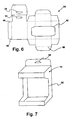
- the blank 64 includes a window 92, a pair of hanger apertures 94, a glue tab 96 and a plurality of fold seams 98 formed therein.
- the blank 64 is erected into a carton 14 by the erecting stations 66 of the carton conveyor 62 ( Fig. 2 ).
- the erecting stations 66 include equipment (not shown) to fold the blank 64 at the seams 98 and apply adhesive to the glue tab 96 to erect the carton 14.
- the window 92 provides an internal view of the contents retained within the carton 14.
- the containers 12 within the multi-pack 10 are externally displayed through the window 92.
- the pair of hanger apertures 94 are aligned during the erecting of the carton 14 to provide a location for receiving a post or hanger (not shown) for organizing the multi-packs 10 at the point of purchase.
- the blank 64 includes an assortment of additional sections that form the support structure of the carton including: a top, bottom, back and side walls.
- alternate embodiments of the product multi-pack 10 envision multi-packs of different quantities of containers 12. These alternate embodiments may include multiples of the two-pack configuration (e.g., four-packs, six-packs). Alternatively, embodiments contemplate a three-pack, or multiples thereof (e.g., six-packs, nine-packs). Still further embodiments envision combinations of two-packs with three-packs (e.g., five-packs and seven-packs).
- Figure 8 illustrates a Four-Pack 100 for supporting and displaying four containers 12.
- the Four-Pack 100 includes a dual window carton 102, having a pair of widows that open on opposite sides of the carton 102. Two pairs of containers 12 are retained within the Four-Pack 100. Each pair of containers 12 is connected by a web 13 (not shown). Each container 12 is oriented relative to its connected container 12, such that the labels 24 face in the same direction, outward of the carton 102.
- Figures 9-10 illustrate a Three-Pack 104 for supporting and displaying three containers 12.
- the Three-Pack 104 includes a large window carton 106, having a large widow that extends along a side of the carton 106.
- Three containers 12 are retained within the Three-Pack 104.
- the containers 12 are connected by a three-web 108.
- the three-web 108 includes a series of apertures 110 for receiving the caps 82 (not shown) of the containers 12.
- the three-web 108 also includes a series of perf-pairs 112 for maintaining tension within the three-web 108 during application to the containers 12.
- the three-web 108 also includes a series of transverse slits 114 that assist the cutting station 54 ( Fig.
- each container 12 is oriented relative to its connected containers 12, such that the labels 24 of the containers face the same direction outward of the carton 104.
Landscapes
- Engineering & Computer Science (AREA)
- Mechanical Engineering (AREA)
- Container Filling Or Packaging Operations (AREA)
- Auxiliary Devices For And Details Of Packaging Control (AREA)
- Wrapping Of Specific Fragile Articles (AREA)
- Packages (AREA)
- Labeling Devices (AREA)
Description
- This application is a continuation-in-part of
U.S. application Serial No. 12/424,139 filed April 15, 2009 - One or more embodiments of the present invention generally relate to a product multi-pack for securing a plurality of oriented containers relative to each other, and a system for orienting and packaging such multi-packs.
- Such package are known e.g. from
JP 2004 106 933 - Container connectors for attaching a plurality of beverage containers, such as beer or soft drink cans, are well known. Such connectors are typically thin flexible sheets of plastic that include a series of apertures. Each aperture is sized for receiving a portion of the can. For example, common "six-pack" connectors include six apertures that are each engageable about an upper ridge of a can. Similar connectors have been used to hold bottles, and non fluid containers.
- Container positioners have been incorporated into cardboard cartons, such as those currently used to display two ounce bottles of 5-hour ENERGY ® dietary supplements. Such container positioners include a cardboard panel having a series of apertures. Each aperture receives a cap of a bottle. The apertures provide frictional resistance that opposes the rotation of the bottles. The carton also includes a window to display the bottles. Once the bottles are placed in the carton, and are engaged by the panel, they may be manually rotated to orient the bottle labels such that they are facing out of the window.
- Systems for packaging and orienting beverage containers are also well known.
U.S. Patent Nos.: 6,868,652 B2 to Arends et al. ,5,074,399 to Kettle et al. , and5,215,180 to Allard et al. disclose examples of such prior art. - Systems for packaging beverage containers, that also include mechanisms for cutting container connectors are also well known.
U.S. Patent Nos.: 3,991,640 to Schlueter ,6,973,760 B2 to Moore ,3,851,445 to Schuh and5,054,257 to Cunningham et al. disclose examples of such prior art. - In at least one embodiment a product multi-pack is provided with a plurality of elongate product containers. The containers each include a bottom, an open top that is closed by a cap and a wall extending there between. The wall includes a label having a front portion extending about a limited section of the wall circumference. A carton is provided that is sized to display the plurality of product containers retained therein. A locator web is provided that is formed of a thin sheet of plastic having a plurality of spaced apart apertures formed therein. The apertures are sized to be at least partially elastically deformed when installed over the caps of the product containers. Additionally, the locator web provides frictional resistance to rotation of the product containers, which enables the containers to be positioned and held in place relative to the carton open face so that the label front portions are visible.
- In another embodiment, a method of packaging at least two of generally circumferentially symmetrically shaped product containers provided with a label having a front portion extending about a limited section of the circumference in an open face carton is provided. The method includes inserting an end of each of at least two product containers into one of a plurality of spaced apart apertures in a plastic web. Additionally the method includes optically sensing the orientation of the product containers. The method provides automatically rotating the product containers to a desired position based on the sensed orientation and the location of the label front portion. The method also includes enclosing the at least two product containers and the interconnecting plastic web into an open face multi-pack carton so that the label front portions of the plurality of product containers are oriented to be visible through the carton open face.
- In another embodiment, a system is provided for filling a multi-pack carton with plurality of elongate generally circumferentially symmetrically shaped product containers. The containers each have a bottom region, an open top closed by a cap and a tubular wall extending there between, with the wall provided with a label having a front portion extending about a limited section of the wall circumference. The system includes a conveyor for conveying product containers through a series of stations. The system provides a controller for receiving signals from the stations, where the controller analyzes the received signals and transmits control signals to the stations in response to the received signals. The system also includes a feed station coupled to the conveyer for organizing product containers to be conveyed. A web application station is provided for installing thin elongate web to the conveyed product containers. The system includes a rotation sensor for measuring a product container indicator position that is indicative of a label orientation and transmitting a corresponding orientation signal to the controller. A product container alignment station is provided for receiving speed control signals from the controller and operating a pair of drive members in response to the received speed control signals for rotating a series of connected conveyed product containers. The system includes a feed sensor for measuring a longitudinal position of the container and transmitting a corresponding feed signal to the controller. A web cutting station is provided for receiving cut command signals from the controller and operating a cutting mechanism in response to the received cut command signals for separating the series of connected conveyed product containers into subassemblies of linked product containers. The system includes a carton feed station for receiving a plurality of carton blanks and erecting a carton from each blank. A transfer station is provided for receiving subassemblies of linked product containers and transferring linked product containers into each carton. And the system includes a carton closing station for closing the carton once filled.
-
-
FIGURE 1 is a side perspective view of a product multi-pack according to an embodiment of the present invention; -
FIGURE 2 is a side elevation view of a system for packaging a product multi-pack according to another embodiment of the present invention; -
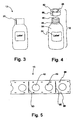
FIGURE 3 is an enlarged side elevation view of a product container ofFigure 1 ; -
FIGURE 4 is an enlarged side perspective view of the product container ofFigure 1 , illustrated with a removable top; -
FIGURE 5 is a top plan view of an elongate web member for receiving the product container ofFigure 3 ; -
FIGURE 6 is a side elevation view of a carton blank ofFigure 1 ; -
FIGURE 7 is a side perspective view of a carton erected from the carton blank ofFigure 6 ; -
FIGURE 8 is a top perspective view of a product multi-pack according to another embodiment of the present invention, illustrated with four product containers; -
FIGURE 9 is a top perspective view of a product multi-pack according to yet another embodiment of the present invention, illustrated with three product containers; -
FIGURE 10 is a top plan view of an elongate web member for receiving the products of the product multi-pack ofFigure 9 ; -
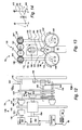
FIGURE 11 is an enlarged top plan view of a portion of the system ofFigure 2 , illustrating an alignment station; -
FIGURE 12 is an enlarged side elevation view of a portion of the system ofFigure 2 , illustrating a cutting station; -
FIGURE 13 is a cross section view of the cutting station ofFigure 12 , taken along the line 13-13; and -
FIGURE 14 is a diagram illustrating a pair of linkage assemblies of the cutting station ofFigure 13 . -
Figure 1 illustrates a product multi-pack for securing and displaying product at a point of purchase, and is generally referenced asnumeral 10. Aproduct multi-pack 10 of the illustrated embodiment includes a pair ofproduct containers 12, aweb 13 and acarton 14 coupled to each other. - The
product containers 12 are elongate containers that are sized for enclosing a consumable product. Thecontainers 12 may be blow molded and generally cylindrical in shape. Theweb 13 is a thin sheet of elastic material that attaches a pair ofcontainers 12 together. Theweb 13 is sized for receiving a portion of each of thecontainers 12, and provides a frictional resistance that opposes rotation of thecontainer 12 relative to theweb 13. Thecarton 14 supports and displays the pair ofcontainers 12 at the point of purchase. - The
containers 12 are circumferentially symmetrical about a vertical axis 16 (Fig. 2 ). Alternate embodiments envision containers having other shapes such as spherical or an "hourglass". Thecontainers 12 include abottom region 18 for resting upon an underlying surface. Thecontainers 12 also include a re-closeable top 20. Atubular wall 22 extends between the bottom 18 and top 20 of eachcontainer 12. Alabel 24 is disposed over a limited section of the circumference of thewall 22. Thelabel 24 includes a logo for the product, such as the 5-hour Energy ® logo. Thecontainers 12 are oriented such that thelabels 24 are both facing the same direction. - An
indicator 26 is provided on the exterior of thecontainer 12, for indicating a rotational position of thelabel 24 relative to the current position of thecontainer 12. For example theindicator 26, may be a marking on the top 20 that correlates to a lateral edge or seam of thelabel 24. Alternatively theindicator 26 may be a lateral marking, edge, seam or an image on thelabel 24 itself. Another embodiment of theindicator 26 envisions an indentation (not shown) on thebottom region 18, that correlates to alabel 24 position. - Referring to
Figure 2 , asystem 28 is provided for orienting and packaging theproduct multi-pack 10. Thesystem 28 includes afirst conveyor belt 29 for conveying theproduct containers 12 through a series of stations. Each station contributes to the overall packaging and orienting of theproduct containers 12. Theconveyor 29 is configured to generally convey thecontainers 12 in a linear direction. Alternate embodiments of theconveyor 29 envision conveying the containers in a non linear direction, or linear with curved portions. - A
controller 30 is provided for communicating with the series of stations of thesystem 28. Thecontroller 30 generally includes any number of microprocessors, ASICs, ICs, memory (e.g., FLASH, ROM, RAM, EPROM and/or EEPROM) and software code to co-act with one another to communicate with the stations ofsystem 28. Thecontroller 30 is configured for receiving signals from the series of stations, indicating various aspects of the individual stations as thecontainers 12 are conveyed along thesystem 28. Thecontroller 30 is also configured for analyzing the received signals, and transmitting signals/commands back to the stations. - The
system 28 includes afeed station 32 for controlling the flow of the conveyedproduct containers 12. Thefeed station 32 receives a plurality ofproduct containers 12, each positioned in a generally upright orientation. Thefeed station 32 is coupled to theconveyor 29, such that thefeed station 32 controls the width and longitudinal spacing of the conveyedcontainers 12. Thefeed station 32 controls the width of the conveyedcontainers 12 by funneling thecontainers 12 into a pre determined lateral spacing. For example, thefeed station 32 may only permit thecontainers 12 to proceed in a single file line along theconveyor 29. Alternate embodiments of thefeed station 32 envision thestation 32 grouping theproduct containers 12 side by side, with multiple containers 12 (e.g. two or three) laterally aligned on theconveyor 29. Additionally, the feed station controls the longitudinal spacing, such that there generally is no space betweenconsecutive containers 12. - The
system 28 also includes aweb application station 34. At theweb application station 34, the elongateplastic web 13 is installed over the laterally aligned series of conveyedcontainers 12. Theweb 13 attaches thecontainers 12 to each other. Theweb application station 34 includes a drive sprocket (spool) 38 for theweb 13 to be wound upon. Thespool 38 is positioned above theconveyor 29, such that theweb 13 extends downward from thespool 38 to longitudinally align with the conveyedcontainers 12. Theweb application station 34 also includes anapplicator mechanism 40 having multiple small spools for installing theweb 13 to eachcontainer 12. - The
web 13 is a thin elongate strip of flexible elastically deformable plastic. Theweb 13 is provided with a series ofapertures 42 projecting through the thickness of theweb 13. Eachaperture 42 is sized for receiving an outer diameter of the top 20 of thecontainer 12. Theweb 13 elastically deforms around eachaperture 42 to conform to and frictionally engage the top 20 of eachcontainer 12. Theapertures 42 are generally centrally oriented about a width of theweb 13, and longitudinally aligned about a length of theweb 13. - Referring to
Figures 2 and11 , analignment station 48 receives the conveyed linkedcontainers 12 from theweb application station 34. Thecontainers 12 are received by thealignment station 48 at anupstream area 120 and exit thealignment station 48 at adownstream area 122. Thealignment station 48 includes afirst drive member 50 and a second drive member 50'. Both drivemembers 50 and 50' upwardly extend from fixtures (not shown) positioned on opposing sides of theconveyor 29. Eachdrive member 50 and 50' operates arotating belt 52 and 52' respectively. The pair ofbelts 52 and 52' are transversely spaced apart and generally aligned parallel to each other. The pair ofdrive members 50 and 50' are configured such that theirrespective belts 52 and 52' frictionally engage opposingwalls 22 of the conveyedcontainers 12. Thebelts 52 and 52' may be sized to simultaneously engage a series of consecutively conveyedcontainers 12. - The
controller 30 independently controls the speed of eachdrive member 50 and 50', to selectively rotate thecontainers 12 as they translate through thealignment station 48. Thecontroller 30 may allow thecontainers 12 to translate through thealignment station 48, without rotating relative to theweb 13, by commanding thedrive members 50 and 50' to drive thebelts 52 and 52' at the same tangential velocity. Additionally, thecontroller 30 may rotate thecontainers 12 about theirrespective axis 16 and relative to theweb 13, by commanding thedrive members 50 and 50' to operate thebelts 52 and 52' at different tangential velocities. Thecontroller 30 is programed with pre-determined data regarding the desired rotational position of eachcontainer 12 once it exits thealignment station 48. - The
alignment station 48 includes arotation sensor 44, that is configured for measuring the rotational position of eachproduct container 12 as it is conveyed through thestation 48. Thesensor 44 detects theindicator 26 on thecontainer 12 and takes a measurement of the position of theindicator 26 relative to a pre-determined coordinate system to measure the rotational position of eachcontainer 12. Thesensor 44 transmits aposition signal 46 "ORIENT_MSMT" to thecontroller 30 that is indicative of the orientation of eachcontainer 12. The pre-determined coordinate system may be a 360 degree polar coordinate system centered about thevertical axis 16 of eachcontainer 12. It is generally recognized that other sensors/measuring devices may be used. The particular type of measuring device that is implemented may vary based on the desired criteria of a particular implementation. - The
controller 30 receives theORIENT_MSMT signal 46 from thesensor 44 and determines the speed required for eachdrive member 50 and 50' to rotate eachcontainer 12 to a desired orientation. Thecontroller 30 may include signal conditioning equipment (not shown) for adjusting and digitizing any such received signals. Thecontroller 30 accesses and analyzes the digitized signals. Thecontroller 30 compares the current orientation of eachcontainer 12 to a pre-determined desired orientation. For example, with reference toFigure 11 , a desired orientation of eachcontainer 12 may correspond to anindicator 26 position of two hundred and seventy degrees (270°) about thevertical axis 16, as illustrated in thecontainers 12 that are exiting thealignment station 48 at thedown stream area 122. Anunoriented container 124 is measured by theposition sensor 44. Thesensor 44 sends a ORIENT_MSMT to thecontroller 30 indicating thatcontainer 30 has an initial position of five degrees (5°). Thecontroller 30 determines that theunoriented container 124 must be rotated ninety five degrees (95°) counter clockwise to be properly oriented. Thecontroller 30 references pre-determined test data to determine that to rotate the unoriented container 124 (95°) counter clockwise, thefirst drive member 50 must rotate faster than the second drive member 50'. Thecontroller 30 transmits a DRIVE_1_CONTROL_SIGNAL to thefirst drive member 50 and a DRIVE_2_CONTROL_SIGNAL to the second drive member 50', corresponding to the calculated values. Thedrive members 50 and 50' receive the control signals, and rotate theunoriented container 124 into the desired oriented position as it exits thealignment station 48. An alternate embodiment of the alignment station includes a position sensor that is positioned in proximity to the upstream area. In such an embodiment, the controller may track the position of each container as it is conveyed through the alignment station. - The
drive members 50 and 50' adjust their output rotational speed based on input signals from thecontroller 30. Eachdrive member 50 and 50' includes a motor and geartrain (not shown) for converting input electrical power into output mechanical rotational power. The motors may be AC or DC. The control signals that are sent to thedrive members 50 and 50' may be indicative of a desired speed, and the drive members adjust their output speed accordingly. Alternate embodiments of thesystem 28 envision that the controller provides the input voltage to the drive members via the control signal, and thereby varies the speed of the drive members motors by varying the input voltage. - With reference to
Figures 2 ,12 and 13 , a cuttingstation 54 receives the series of connected and oriented conveyedcontainers 12 from thealignment station 48, and separates them into subassemblies of linkedcontainers 12. For example the cuttingstation 54 of the illustrated embodiment separates thecontainers 12 into subassemblies of two linkedcontainers 12. The cuttingstation 54 includes afeed sensor 56 and atransverse cutting mechanism 58 operatively coupled to each other. Thesensor 56 measures the longitudinal position of thecontainers 12 and transmits acorresponding feed signal 60 to thecontroller 30. Thefeed sensor 56 may be a laser sensor that is positioned to indicate the presence of acontainer 12. It is generally recognized that other sensors/measuring devices may be used. The particular type of measuring device that is implemented may vary based on the desired criteria of a particular implementation. Thecontroller 30 analyzes thesignal 60 and commands thecutting mechanism 58 to actuate and transversely cut theweb 13 thereby separating the series ofcontainers 12 into subassemblies of linkedcontainers 12. - The
cutting mechanism 58 includes abelt drive 130 for rotating a pair ofblades 132 and 132'. Thebelt drive 130 includes abelt motor 134, abelt gear train 136 and a pair of belts 138 and 138' that are coupled to each other. Thegear train 136 includes amotor gear 140, anidler gear 142 and a pair of belt gears 144 and 144'. Themotor gear 140 is fixed to an output shaft of themotor 134. Theidler gear 142 meshes with themotor gear 140. One belt gear 144' is driven by themotor gear 140 and anotherbelt gear 144 is driven by theidler gear 142, such that the belt gears 144 and 144' rotate in opposite directions. Eachbelt gear 144 and 144' is fixed to abelt axle 146 and 146', such that theaxles 146 and 146' rotate with thegears 144 and 144'. Each belt 138 and 138' is driven by one of thebelt axles 146 and 146'. Each belt 138 and 138' is also connected to ablade shaft 148 and 148', for rotating acorresponding blade 132 and 132'. Since the belt gears 144 and 144' rotate in opposite directions relative to each other, the corresponding belts 138 and 138' andblades 132 and 132' also rotate in opposite directions. - The
cutting mechanism 58 includes ablade drive 150 for actuating the rotating pair ofblades 132 and 132' through an arcuate path to transversely cut theweb 13. Theblade drive 150 includes aservo motor 152, a slider crank 154 and a pair ofsymmetric linkage assemblies 156 and 156' that are coupled to each other. Theservo motor 152 is configured for rotating aservo output shaft 158 at approximately one hundred and eighty degree (180°) increments. The slider crank 154 includes a crank 160 coupled to a connectingrod 164. Acrank 160 is fixed to a distal end of theoutput shaft 158. Thecrank 160 includes apost 162 that is axially adjacent to theoutput shaft 158, such that thepost 162 revolves around theshaft 158. The connectingrod 164 receives thepost 162 of thecrank 160. An opposite end of the connectingrod 164 is coupled to atransverse axle 166. Thetransverse axle 166 is constrained within alinear guide bearing 168. Thus the slider crank 154 converts rotation (crank) of theservo output shaft 158 into translation (slide) of thetransverse axle 166. The pair ofsymmetric linkage assemblies 156 and 156' are coupled to the slider crank 154 at thetransverse axle 166. A pair of drivenlinks 170 and 170' couple thetransverse axle 166 to theblade shafts 148 and 148'. A pair ofidler links 172 and 172' couple theblade shafts 148 and 148' to thebelt axles 146 and 146'. Thus theservo motor 152 drives the slider crank 154 which translates thetransverse axle 166 up and down. As thetransverse axle 166 translates upward, the drivenlinks 170 and 170' pivot upward and theidler links 172 and 172' pivot inward, thereby actuating theblades 132 and 132' to transversely cut theweb 13. Then as thetransverse axle 166 translates downward, the drivenlinks 170 and 170' pivot downward and theidler links 172 and 172' pivot outward, thereby actuating theblades 132 and 132' away from theweb 13. -
Figure 14 illustrates the arcuate motion of theblades 132 and 132' as provided by thelinkage assemblies 156 and 156'. The solid lines represent the position of the drivenlinks 170 and 170' and theidler links 172 and 172' in a cutting position. The dashed lines represent the position of the drivenlinks 170 and 170' and theidler links 172 and 172' in an open position, where theblades 132 and 132' are actuated away from thecontainers 12. - The arcuate path of the
blades 132 and 132' may be altered by adjusting the position of theservo motor 152. Theservo motor 152 is adjustably mounted to a fixture of the cuttingstation 54, such that the height of theservo 152 relative to theconveyor 29 may be adjusted. By adjusting the height of theservo 152 the cutting position and the open position may be altered. For example, as the height of theservo 152 increases, theblades 132 and 132' are closer to each other at both the cutting position and the open position. Such an adjustment may be needed to accommodatewebs 13 of varying transverse widths. - The
system 28 includes acarton conveyor line 62 that is positioned adjacent to thefirst conveyor 29. Thecarton conveyor 62 receives a plurality ofcarton blanks 64. Theconveyor 62 passes theblanks 64 through a series of carton erecting stations 66 to erect thecarton 14. Thecarton 14 is positioned for receiving a subassembly of linkedcontainers 12. - The
first conveyor 29 includes atransfer station 68 for individually transferring subassemblies of linkedcontainers 12 to thecarton conveyor line 62. Thetransfer station 68 includes atransverse dial 70 for receiving linkedcontainers 12. Thedial 70 is transversely aligned relative to the longitudinal length of thefirst conveyor 29. Thedial 70 rotates about an axis (not shown) that is positioned below an upper planar surface of theconveyor 29, such that a portion of the circumferential edge of thedial 70 extends above theconveyor 29. A series of pockets 72 are formed within the portion of the circumferential edge of thedial 70. The pockets 72 are sized for receiving the linkedcontainers 12. At a first dial position, the pocket 72 receives the linkedcontainers 12. The controller commands thedial 70 to rotate from the first dial position to a second dial position. An ejection system (not shown) is coupled to thedial 70, for ejecting the linkedcontainers 12 at the second dial position. The linkedcontainers 12 are ejected from the second dial position, and received by thecarton 14 of thecarton conveyor line 62. - An opened
carton 14 is positioned on thecarton conveyor line 62 to receive the linkedcontainers 12 and proceeds to complete the packaging process. After receiving thecontainers 12 within theopen carton 14, theconveyor line 62 closes thecarton 14 to form amulti-pack 10. Thecarton conveyor line 62 may include additional stations for packaging an assortment ofmulti-packs 12 within a box 76, and palletizing a plurality of boxes on a pallet 78. - Alternate embodiments of the
system 28, envision the addition of a leak test station (not shown) for detecting defective containers. Such a leak test station may be coupled to theconveyor 29, upstream of thefeed station 32. A leak test station would squeezecontainers 12 for detecting fractures or improper product volumes within thecontainers 12. - Regarding
Figures 3-4 , thecontainer 12 is provided with the re-closeable top 18, so that a user may open the top 18, consume some of the product inside, then re-close the top 18. Thecontainer 12 includes anopening 80 and a cap 82 that are operatively coupled to each other. For example theopening 80 may be an externally threaded neck, and the cap 82 may include internal threads (not shown). - The
container 12 is sized for enclosing a nominal volume of fluid, such as 2 fluid ounces. Alternate embodiments envision containers for enclosing solid products such as medicine or vitamins. Additional alternate embodiments envision containers for larger volumes of fluid, such as 4 or 6 ounces. - A shrink wrap plastic covering 84 is disposed over a substantial portion of the outer circumference of the
container 12 and acts as a seal. The covering 84 axially extends along thewall 22 of thecontainer 12 to partially cover the cap 82. The covering 84 includes a pair of perforated regions that act as a seal for thecontainer 12, by both preventing the cap 82 from inadvertently unscrewing and also for visually indicating to a user that the cap 82 had previously been unscrewed or "tampered with". Aperforated ring 85 extends along the circumference ofcontainer 12 at the base of the cap 82. Atear strip 86 extends from thering 85 to an edge of the covering 84 on the top of the cap 82. To open acontainer 12, a user may remove thetear strip 86, then unscrew the cap 82, which breaks theperforated ring 85. The covering 84 may include thelabel 24 formed within, or the covering 84 may be generally transparent and formed over thelabel 24. Alternate embodiments of thecontainer 12, envision a seal, comprised by a 2-piece cap assembly (not shown), whereby a lower ring is detached from the cap during the first time the seal is broken. Such a seal is commonly used in the soft drink industry. - With respect to
Figure 5 , theweb 13 is made of a thin elastic polymer that is sized for receiving thecontainers 12. Theweb 13 may be formed of an elastic polymer such as polyethylene (PE) or polypropylene (PP) or low density polyethylene (LDPE). Theweb 13 includes the series ofapertures 42 for receiving the caps 82 (Figs. 3-4 ) of thecontainers 12. The outer diameter of the cap 82 is generally larger than the inner diameter of theaperture 42, thereby providing an interference fit. Theweb 13 elastically deforms to receive the cap 82 of thecontainer 12. The cap/web interface provides a frictional resistance that opposes the rotation and translation (pull-out) of thecontainer 12 relative to theweb 13. The frictional resistance helps maintain the oriented position of thecontainers 12. For example, an interference fit may be provided by aweb 13 havingapertures 42 with inner diameters of 0.812 inches, that are sized to receivecontainers 12 having caps 82 with outer diameters of 0.895 inches. - The
web 13 includes a series of pairs of perforations (perf-pairs) 88 for maintaining tension within theweb 13 during application of theweb 13 to thecontainers 12. The perf-pairs 88 are transversely spaced apart pairs of slots that are longitudinally spaced along the length of theweb 13. The perf-pairs 88 are sized for receiving pins (not shown) that radially extend from the circumference of the spool 38 (Fig. 2 ), and also radially extend from the circumference of the small spools of the applicator 40 (Fig. 2 ). - The
web 13 also includes a series oftransverse slits 90 that assist the cutting station 54 (Fig. 2 ) in separating the series ofcontainers 12 into subassemblies of linkedcontainers 12. Theslits 90 extend partially across the width of theweb 13. However theslits 90 terminate short of the opposed transverse edges of theweb 13. The width of theweb 13 is approximately equal to the maximum diameter of thecontainer 12. At the cuttingstation 54, thecontroller 30 commands thetransverse cutting mechanism 58 to cut theweb 13 at each slit 90, thereby separating the series ofcontainers 12 into linkedcontainers 12. In the illustrated embodiment, there are at least twoapertures 42 and three pairs ofperforations 88 betweenadjacent slits 90, therefore the cuttingstation 54 separates the series ofcontainers 12 into subassemblies of two linkedcontainers 12. The length of a portion of theweb 13, after it is cut by the cuttingstation 54, is approximately equal to the maximum diameter of thecontainer 12 multiplied by the number ofcontainers 12 that are linked in the subassembly. - Regarding
Figures 6-7 , acarton 14 is provided for supporting and displayingproduct containers 12 that are retained therein. A die-cut carton blank 64 may be formed from a sheet of cardboard. The blank 64 includes awindow 92, a pair ofhanger apertures 94, aglue tab 96 and a plurality of fold seams 98 formed therein. The blank 64 is erected into acarton 14 by the erecting stations 66 of the carton conveyor 62 (Fig. 2 ). The erecting stations 66 include equipment (not shown) to fold the blank 64 at theseams 98 and apply adhesive to theglue tab 96 to erect thecarton 14. Once erected, thewindow 92 provides an internal view of the contents retained within thecarton 14. For example, thecontainers 12 within themulti-pack 10, are externally displayed through thewindow 92. The pair ofhanger apertures 94 are aligned during the erecting of thecarton 14 to provide a location for receiving a post or hanger (not shown) for organizing themulti-packs 10 at the point of purchase. The blank 64 includes an assortment of additional sections that form the support structure of the carton including: a top, bottom, back and side walls. - With reference to
Figures 8-10 , alternate embodiments of theproduct multi-pack 10 envision multi-packs of different quantities ofcontainers 12. These alternate embodiments may include multiples of the two-pack configuration (e.g., four-packs, six-packs). Alternatively, embodiments contemplate a three-pack, or multiples thereof (e.g., six-packs, nine-packs). Still further embodiments envision combinations of two-packs with three-packs (e.g., five-packs and seven-packs). -
Figure 8 illustrates a Four-Pack 100 for supporting and displaying fourcontainers 12. The Four-Pack 100 includes adual window carton 102, having a pair of widows that open on opposite sides of thecarton 102. Two pairs ofcontainers 12 are retained within the Four-Pack 100. Each pair ofcontainers 12 is connected by a web 13 (not shown). Eachcontainer 12 is oriented relative to itsconnected container 12, such that thelabels 24 face in the same direction, outward of thecarton 102. -
Figures 9-10 illustrate a Three-Pack 104 for supporting and displaying threecontainers 12. The Three-Pack 104 includes alarge window carton 106, having a large widow that extends along a side of thecarton 106. Threecontainers 12 are retained within the Three-Pack 104. Thecontainers 12 are connected by a three-web 108. The three-web 108 includes a series ofapertures 110 for receiving the caps 82 (not shown) of thecontainers 12. The three-web 108 also includes a series of perf-pairs 112 for maintaining tension within the three-web 108 during application to thecontainers 12. The three-web 108 also includes a series oftransverse slits 114 that assist the cutting station 54 (Fig. 2 ) in separating the series ofcontainers 12 into linked sub-assemblies. In this embodiment, there are threeapertures 110 and four pairs ofperforations 112 betweenadjacent slits 114, therefore the cuttingstation 54 separates the series ofcontainers 12 into subassemblies of three linkedcontainers 12. Eachcontainer 12 is oriented relative to itsconnected containers 12, such that thelabels 24 of the containers face the same direction outward of thecarton 104. - While embodiments of the invention have been illustrated and described, it is not intended that these embodiments illustrate and describe all possible forms of the invention. Rather, the words used in the specification are words of description rather than limitation, and it is understood that various changes may be made without departing from the spirit and scope of the invention. Additionally, the features of various implementing embodiments may be combined to form further embodiments of the invention
Claims (15)
- A product multi-pack (10), comprising:a plurality of elongate generally circumferentially symmetrically shaped product containers (12), each having a bottom region, an open top closed by a cap (82) and a tubular wall (22) extending there between, with the wall provided with a label (24) having a front portion extending about a limited section of the wall circumference;a carton (14) sized to display the plurality of product containers, preferably sized to contain at least two product containers, retained therein, the carton having an open face exposing a portion of the product container wall; anda locator web (13) formed of a thin sheet of plastic having a plurality of spaced apart apertures (42) formed therein and sized to be at least partially elastically deformed when installed over the caps of the product containers;wherein the locator web provides frictional resistance to rotation of the product containers enabling the containers to be positioned and held in place relative to the carton open face so that the label front portions are visible.
- The product multi-pack (10) of claim 1 wherein the cap (82) of the product containers (12) has an outer diameter that is larger than a corresponding inner diameter of the aperture, such that an interference fit is formed when the cap is inserted into the aperture of the web, the interference fit providing the frictional resistance to rotation of the container.
- The product multi-pack of claim 1 wherein the web (13) has a width approximately equal to the maximum diameter of the product containers (12) and a length approximately equal to the width multiplied by the number of product containers interconnected by the web.
- A method of packaging at least two product containers (12) of the multi-pack (10) of claim 1, the method comprising:inserting an end of each of the at least two product containers into one of a plurality of spaced apart apertures (42) in the locator web of the multi-pack of claim 1;optically sensing the orientation of the product containers;automatically rotating the product containers to a desired position based on the sensed orientation and the location of the label front portion; andenclosing the at least two product containers and the interconnecting locator web into the carton (14) of the multi-pack of claim 1 so that the label front portions of the plurality of product containers are oriented to be visible through the carton open face.
- The method of claim 4, wherein each aperture (42) elastically deforms when the end of the product container (12) is inserted, thereby the aperture conforms to and frictionally engages the end of the product container (12).
- The method of claim 4, wherein a pair of drive members (50) frictionally engage the product containers (12) to automatically rotate the product containers relative to the locator web (13) so that the label position of the product container when released from the drive members is in a desired position based on the sensed orientation and the location of the label front portion.
- The method of claim 4, further comprising cutting the locator web (13) at spaced apart positions between adjacent apertures forming a plurality of product containers interconnected by a web segment with the labels (24) oriented in a desired position.
- A system of filling a carton (14) of the multi-pack of claim 1 with a plurality of product containers (12) of the multi-pack of claim 1, the system comprising:a conveyor (29) for conveying the product containers through a series of stations;a controller (30) for receiving signals from the stations, the controller analyzes the received signals and transmits control signals to the stations in response to the received signals;a feed station (32) coupled to the conveyer for organizing the product containers to be conveyed;a web application station (34) for installing the locator web (13) of the multi-pack of claim 1 to the conveyed product containers;a rotation sensor (44) for measuring a product container indicator position that is indicative of a label orientation and transmitting a corresponding orientation signal to the controller;a product container alignment station (48) for receiving speed control signals from the controller and operating a pair of drive members (50) in response to the received speed control signals for rotating a series of connected conveyed product containers;a feed sensor (56) for measuring a longitudinal position of the container and transmitting a corresponding feed signal to the controller;a web locator cutting station (54) for receiving cut command signals from the controller and operating a cutting mechanism (58) in response to the received cut command signals for separating the series of connected conveyed product containers into subassemblies of linked product containers;a carton feed station (32) for receiving a plurality of carton blanks (64) and erecting a carton from each blank;a transfer station (68) for receiving subassemblies of linked product containers and transferring linked product containers into each carton; anda carton closing station for closing the carton once filled.
- The system of claim 8 wherein the product container alignment station (48) further comprises a pair of rotating belts (29) that are each operated by one of the drive members (50), the belts are generally aligned parallel to each other for simultaneously engaging opposing walls (22) of the conveyed containers (12).
- The system of claim 9 wherein the controller (30) compares the orientation signal to a pre determined container orientation to determine the speed required from each of the drive members (50) for rotating the container (12) to the pre determined container orientation.
- The system of claim 8 wherein the cutting mechanism (58) further comprises a belt drive for rotating a pair of opposing blades.
- The system of claim 11 wherein each of the opposing blades are generally disc shaped and positioned coplanar relative to each other, and/or
wherein the belt drive further comprises a motor and a gear train for simultaneously rotating the pair of opposing blades in opposite directions. - The system of claim 8 wherein the cutting mechanism (58) further comprises a blade drive for actuating a pair of opposing blades through an arcuate path to transversely cut the connected product containers (12), preferably
wherein the blade drive further comprises a slider crank for converting the controlled rotation of a servo motor into the translation of a transverse axle for actuating the blades. - The system of claim 13 wherein the servo motor rotates in increments of at least one hundred and eighty degrees, and/or
wherein the blade drive further comprises a pair of symmetric linkage assemblies that are coupled to the transverse axle for controlling the actuation of the opposing blades through the arcuate path. - The system of claim 14 wherein the pair of symmetric linkage assemblies each include a driven link that couples the transverse axle to the blade and an idler link that couples the blade to a fixed pivot, such that as the transverse axle translates upward, the driven links pivot upward and the idler links pivot inward, thereby actuating the blades to transversely cut the connected product containers, and as the transverse axle translates downward, the driven links pivot downward and the idler links pivot outward, thereby moving the blades away from the connected product containers (12), especially
wherein a height of the servo motor relative to the conveyor may be adjusted for setting a start location and a stop location of each blade along its arcuate path.
Applications Claiming Priority (2)
| Application Number | Priority Date | Filing Date | Title |
|---|---|---|---|
| US12/424,139 US20100264058A1 (en) | 2009-04-15 | 2009-04-15 | Product multi-pack |
| PCT/US2009/045970 WO2010120319A1 (en) | 2009-04-15 | 2009-06-02 | Product multi-pack and a system for orienting and packaging such multi-packs |
Publications (3)
| Publication Number | Publication Date |
|---|---|
| EP2419339A1 EP2419339A1 (en) | 2012-02-22 |
| EP2419339A4 EP2419339A4 (en) | 2012-10-03 |
| EP2419339B1 true EP2419339B1 (en) | 2015-03-25 |
Family
ID=42980195
Family Applications (1)
| Application Number | Title | Priority Date | Filing Date |
|---|---|---|---|
| EP09843469.9A Active EP2419339B1 (en) | 2009-04-15 | 2009-06-02 | Product multi-pack and a system for orienting and packaging such multi-packs |
Country Status (17)
| Country | Link |
|---|---|
| US (2) | US20100264058A1 (en) |
| EP (1) | EP2419339B1 (en) |
| JP (1) | JP5270039B2 (en) |
| KR (1) | KR101640276B1 (en) |
| CN (1) | CN102438907B (en) |
| AU (1) | AU2009344301B2 (en) |
| BR (1) | BRPI0923971B1 (en) |
| CA (1) | CA2754099C (en) |
| CL (2) | CL2011002322A1 (en) |
| CO (1) | CO6501172A2 (en) |
| EC (1) | ECSP11011312A (en) |
| ES (1) | ES2540234T3 (en) |
| IL (1) | IL214889A (en) |
| MX (1) | MX2011010755A (en) |
| PT (1) | PT2419339E (en) |
| SG (2) | SG2014006019A (en) |
| WO (1) | WO2010120319A1 (en) |
Families Citing this family (41)
| Publication number | Priority date | Publication date | Assignee | Title |
|---|---|---|---|---|
| US20100072163A1 (en) | 2008-09-23 | 2010-03-25 | Bio Clinical Development, Inc. | Bottle cap |
| DE102011083377A1 (en) * | 2011-09-26 | 2013-03-28 | Krones Aktiengesellschaft | Apparatus and method for aligning containers |
| US20130325670A1 (en) | 2012-05-30 | 2013-12-05 | Liberty Hardware Mfg. Corp. | Shower door assembly display and retail |
| GB201217466D0 (en) * | 2012-09-29 | 2012-11-14 | Meadwestvaco Packaging System Llc | Packaging machine and method of packaging articles |
| EP2909103B1 (en) * | 2012-10-16 | 2016-09-21 | Celgene Corporation | Packaging for medicine for clinical trials or commercial use |
| USD712246S1 (en) * | 2012-11-08 | 2014-09-02 | Apple Inc. | Package |
| USD696935S1 (en) * | 2013-01-11 | 2014-01-07 | Carl Zeiss Sports Optics Gmbh | Package for a binocular |
| USD696936S1 (en) * | 2013-01-11 | 2014-01-07 | Carl Zeiss Sports Optics Gmbh | Package for a scope |
| USD700048S1 (en) * | 2013-07-17 | 2014-02-25 | Colgate-Palmolive Company | Oral care implement package |
| USD700047S1 (en) * | 2013-07-17 | 2014-02-25 | Colgate-Palmolive Company | Oral care implement package |
| USD758771S1 (en) | 2014-01-29 | 2016-06-14 | Liberty Hardware Mfg. Corp. | Shower door display |
| US10070739B2 (en) | 2014-01-29 | 2018-09-11 | Liberty Hardware Mfg. Corp. | Shower door assembly display |
| US9676543B2 (en) * | 2014-01-29 | 2017-06-13 | Liberty Hardware Mfg. Corp. | Shower door glass pane packaging assembly |
| USD763023S1 (en) | 2014-01-29 | 2016-08-09 | Liberty Hardware Mfg. Corp. | Shower door display |
| JP6277287B2 (en) * | 2014-03-31 | 2018-02-07 | クーパーヴィジョン インターナショナル ホウルディング カンパニー リミテッド パートナーシップ | Contact lens packaging and method of manufacturing packaged contact lenses |
| CN103950578A (en) * | 2014-04-21 | 2014-07-30 | 昆山达功电子有限公司 | Transformer arraying device |
| US9339437B2 (en) * | 2014-10-09 | 2016-05-17 | Atlantic Health System, Inc. | Medicinal storage, safety, organizational and delivery device |
| DE102014222187A1 (en) * | 2014-10-30 | 2016-05-04 | Krones Aktiengesellschaft | Method of attaching a bottle clip and packaging device |
| KR200482053Y1 (en) * | 2014-12-02 | 2016-12-09 | 주식회사 두남 | Packing structure for multi tap |
| US9907415B2 (en) * | 2015-03-13 | 2018-03-06 | Liberty Hardware Mfg. Corp. | Article divider assembly |
| US9743810B2 (en) | 2015-07-31 | 2017-08-29 | Liberty Hardware Mfg. Corp. | Shower door guide assembly |
| WO2017147149A2 (en) | 2016-02-24 | 2017-08-31 | Celgene Corporation | Nested packaging for pharmaceutical products, and methods of distributing pharmaceutical products using same |
| DE102016112789A1 (en) * | 2016-07-12 | 2018-01-18 | Krones Ag | Method and device for labeling first packaging |
| WO2018194919A1 (en) | 2017-04-18 | 2018-10-25 | Westrock Packaging Systems, Llc | Carton and blank therefor |
| USD921480S1 (en) * | 2017-06-06 | 2021-06-08 | The Procter & Gamble Company | Package for oral care products |
| CN107226334A (en) * | 2017-06-07 | 2017-10-03 | 上海佳万智能科技有限公司 | Body turns to adjusting apparatus |
| CN108466722B (en) * | 2018-03-19 | 2023-08-01 | 江苏昊晟塑业科技有限公司 | Finished product metering and packaging device of plastic extruding machine |
| KR102069975B1 (en) | 2018-06-27 | 2020-02-11 | 박종성 | Packaging container for container products |
| USD874261S1 (en) | 2018-06-29 | 2020-02-04 | L. Perrigo Company | Carton |
| USD874260S1 (en) * | 2018-06-29 | 2020-02-04 | L. Perrigo Company | Carton |
| CN112823125B (en) * | 2018-07-27 | 2023-04-14 | 赛诺菲巴斯德 | Ready-to-sell packaging unit containing at least one pharmaceutical product |
| DE102019113177A1 (en) * | 2019-05-17 | 2020-11-19 | Krones Aktiengesellschaft | Packaging device for articles or article groups and method for applying a cardboard blank to an article or article group |
| CN110282236A (en) * | 2019-07-30 | 2019-09-27 | 珠海凯邦电机制造有限公司 | Packaging structure of motor |
| KR102321591B1 (en) * | 2019-09-19 | 2021-11-05 | (주)일광에프앤에스 | Bundle bag manual packaging device |
| US11365020B1 (en) * | 2020-03-30 | 2022-06-21 | Amazon Technologies, Inc. | Defect prevention for flexible container sealing systems |
| USD1003710S1 (en) * | 2020-04-28 | 2023-11-07 | The Procter & Gamble Company | Over the counter medicinal container with surface ornamentation |
| USD1008798S1 (en) | 2020-04-28 | 2023-12-26 | The Procter & Gamble Company | Over the counter medicinal container with surface ornamentation |
| US12371220B2 (en) * | 2020-07-20 | 2025-07-29 | Tejas Tanna | Strapped leaflet unit embedded in a packaging container |
| US12623808B2 (en) * | 2021-10-22 | 2026-05-12 | The Gillette Company Llc | Consumer product package |
| US20250074681A1 (en) * | 2023-09-01 | 2025-03-06 | Ring Container Technologies, Llc | Container and packaging system |
| USD1109599S1 (en) * | 2024-03-07 | 2026-01-20 | Best Accessory Group LLC | Package for personal care items |
Citations (1)
| Publication number | Priority date | Publication date | Assignee | Title |
|---|---|---|---|---|
| JP2004106933A (en) * | 2002-09-20 | 2004-04-08 | Dainippon Printing Co Ltd | Carton with window |
Family Cites Families (50)
| Publication number | Priority date | Publication date | Assignee | Title |
|---|---|---|---|---|
| US2807404A (en) * | 1955-06-09 | 1957-09-24 | Container Corp | Window carton with cushioning structure |
| US3404505A (en) * | 1965-01-27 | 1968-10-08 | Owens Illinois Inc | Method for packaging containers |
| US3383827A (en) * | 1965-12-10 | 1968-05-21 | Owens Illinois Inc | Multi-pack container carrier and method of assembling to containers |
| US3415350A (en) * | 1966-10-24 | 1968-12-10 | Fmc Corp | Article orienting apparatus |
| US3580380A (en) * | 1968-09-11 | 1971-05-25 | Reynolds Metals Co | Method of and apparatus for orienting indicia bearing cylindrical objects |
| US3541751A (en) * | 1968-09-18 | 1970-11-24 | Illinois Tool Works | Method and apparatus for packaging a plurality of articles in predetermined arrangement |
| US3760554A (en) * | 1969-07-07 | 1973-09-25 | L Arneson | Method and apparatus for assembling a container package |
| US3733100A (en) * | 1971-05-05 | 1973-05-15 | Illinois Tool Works | Container carrier stock |
| US3742677A (en) * | 1971-07-21 | 1973-07-03 | Owens Illinois Inc | Method and apparatus for applying a carrier to a cluster of containers |
| US3826060A (en) * | 1972-11-24 | 1974-07-30 | Pneumatic Scale Corp | Apparatus for applying carrying grids to bottles |
| US3870221A (en) * | 1973-10-09 | 1975-03-11 | Packaging Corp America | Folding carton |
| US3877198A (en) * | 1973-11-08 | 1975-04-15 | Pneumatic Scale Corp | Apparatus for applying carrier grids to bottles |
| US3867807A (en) * | 1973-11-19 | 1975-02-25 | Owens Illinois Inc | Carrier applicator machine for bottles |
| US4051366A (en) * | 1975-12-31 | 1977-09-27 | United Technologies Corporation | Optical apparatus for sensing clustered package orientation |
| US4024950A (en) * | 1976-06-21 | 1977-05-24 | Adolph Coors Company | Multi-container package |
| GB2035959B (en) * | 1978-10-02 | 1982-09-15 | Bowater Packaging Ltd | Window carton |
| EP0015780B1 (en) * | 1979-03-13 | 1983-06-29 | P.L.G. Research Limited | A container pack, a device and band for holding containers together and method of making the same |
| US4231209A (en) * | 1979-07-10 | 1980-11-04 | Royal Crown Cola Company | Self-synchronizing bottle carrier applicator |
| US4509639A (en) * | 1982-04-01 | 1985-04-09 | Tri-Tech Systems International Inc. | Multi-container carrier package and a method of assembly therefor |
| JPS58174476U (en) * | 1982-05-18 | 1983-11-21 | 十條セントラル株式会社 | Portable cartons for bottles and cans |
| US4471870A (en) * | 1982-07-14 | 1984-09-18 | Owens-Illinois, Inc. | Package for holding a plurality of discrete container assemblies |
| GB8728486D0 (en) * | 1987-12-04 | 1988-01-13 | Metal Box Plc | Orientation of containers |
| US4941573A (en) * | 1988-05-26 | 1990-07-17 | Color Ident Systems Corporation | Package identification system |
| CN2038893U (en) * | 1988-08-26 | 1989-06-07 | 栾恤俭 | Multi-bottle bundling machine for bottled products in thin-neck bottles |
| DE4011398C2 (en) * | 1990-04-09 | 1994-09-22 | Alcoa Gmbh Verpackwerke | Device and method for applying screw caps to containers |
| US5215180A (en) * | 1991-06-06 | 1993-06-01 | Carnaudmetalbox Plc | Can orientation apparatus |
| CN2189117Y (en) * | 1993-09-30 | 1995-02-08 | 丁俊权 | Beer bundling machine |
| SE503842C2 (en) * | 1994-10-08 | 1996-09-16 | Haakan Edqvist | Method and apparatus for determining cylindrical objects |
| US5590776A (en) * | 1995-10-06 | 1997-01-07 | Galbierz; Richard T. | Multi-pack carrier for bottles |
| US5695232A (en) * | 1995-11-16 | 1997-12-09 | Tipp; Raymond P. | Bottle carrier |
| US5695050A (en) * | 1996-06-10 | 1997-12-09 | Illinois Tool Works Inc. | Container carrier with different coefficients of friction |
| US5947367A (en) * | 1997-02-10 | 1999-09-07 | The C. W. Zumbiel Co. | Sleeve style bottle carton |
| US5813193A (en) * | 1997-03-24 | 1998-09-29 | Owens-Illinois Labels Inc. | Method and apparatus for applying carriers to containers |
| US5845776A (en) * | 1997-07-16 | 1998-12-08 | Eco-Pak Products, Inc. | Multi-pack carrier for bottles |
| US7146784B1 (en) * | 1998-01-16 | 2006-12-12 | Meadwestvaco Packaging Systems, Llc | Machine for packaging a plurality of articles in a carton, and method of forming a carton |
| JPH11258739A (en) * | 1998-03-13 | 1999-09-24 | Fuji Photo Film Co Ltd | Package for photographic film cartridge |
| US6024219A (en) * | 1998-10-30 | 2000-02-15 | Kraft Foods, Inc. | Display packages |
| US6523328B1 (en) * | 1999-09-13 | 2003-02-25 | Gilbert L. De Cardenas | System and apparatus for an automated container filling production line |
| US6868652B2 (en) * | 2000-01-24 | 2005-03-22 | Illinois Tool Works, Inc. | System and method for packaging oriented containers |
| US6484478B1 (en) * | 2000-01-24 | 2002-11-26 | Illinois Tool Works Inc. | System and method for packaging oriented containers |
| US6964144B1 (en) * | 2000-11-16 | 2005-11-15 | Illinois Tool Works Inc. | System and apparatus for packaging containers |
| GB0110043D0 (en) * | 2001-04-24 | 2001-06-13 | Unilever Plc | Cosmetic regime package |
| US6932265B2 (en) * | 2002-10-17 | 2005-08-23 | Smurfit-Stone Container Enterprises, Inc. | Box convertible to a display container and method of making same |
| US7198070B1 (en) * | 2003-09-24 | 2007-04-03 | Bissell Homecare, Inc. | Assembling aerosol container packages |
| US7360647B2 (en) * | 2004-01-08 | 2008-04-22 | Ogg Design, Inc. | Packaging system and method |
| US20080257763A1 (en) * | 2004-01-08 | 2008-10-23 | Richard Ogg | Packaging System and Method |
| ITMI20041269A1 (en) * | 2004-06-24 | 2004-09-24 | Paper Converting Machine Co | CUTTING BLADE CONTROL SYSTEM PARTICULARLY FOR CUTTING MACHINES FOR LOG CUTTING OF SHEET MATERIAL |
| US7617933B2 (en) * | 2005-05-20 | 2009-11-17 | Meadwestvaco Packaging Systems, Llc | Product dispensing aids |
| GB2441991A (en) * | 2006-09-19 | 2008-03-26 | Meadwestvaco Packaging Systems | Orientating articles in a package |
| EP2084068A1 (en) * | 2006-09-19 | 2009-08-05 | MeadWestvaco Packaging Systems LLC | Article alignment apparatus |
-
2009
- 2009-04-15 US US12/424,139 patent/US20100264058A1/en not_active Abandoned
- 2009-06-02 EP EP09843469.9A patent/EP2419339B1/en active Active
- 2009-06-02 MX MX2011010755A patent/MX2011010755A/en active IP Right Grant
- 2009-06-02 ES ES09843469.9T patent/ES2540234T3/en active Active
- 2009-06-02 WO PCT/US2009/045970 patent/WO2010120319A1/en not_active Ceased
- 2009-06-02 AU AU2009344301A patent/AU2009344301B2/en active Active
- 2009-06-02 CN CN200980158807.5A patent/CN102438907B/en active Active
- 2009-06-02 KR KR1020117024179A patent/KR101640276B1/en not_active Expired - Fee Related
- 2009-06-02 SG SG2014006019A patent/SG2014006019A/en unknown
- 2009-06-02 JP JP2012505872A patent/JP5270039B2/en active Active
- 2009-06-02 PT PT98434699T patent/PT2419339E/en unknown
- 2009-06-02 BR BRPI0923971-5A patent/BRPI0923971B1/en active IP Right Grant
- 2009-06-02 SG SG2011057114A patent/SG173600A1/en unknown
- 2009-06-02 CA CA2754099A patent/CA2754099C/en active Active
-
2011
- 2011-08-30 IL IL214889A patent/IL214889A/en active IP Right Grant
- 2011-09-19 EC EC2011011312A patent/ECSP11011312A/en unknown
- 2011-09-20 CL CL2011002322A patent/CL2011002322A1/en unknown
- 2011-09-30 CO CO11128533A patent/CO6501172A2/en not_active Application Discontinuation
-
2012
- 2012-04-30 US US13/460,057 patent/US8424276B2/en active Active
-
2013
- 2013-06-19 CL CL2013001809A patent/CL2013001809A1/en unknown
Patent Citations (1)
| Publication number | Priority date | Publication date | Assignee | Title |
|---|---|---|---|---|
| JP2004106933A (en) * | 2002-09-20 | 2004-04-08 | Dainippon Printing Co Ltd | Carton with window |
Also Published As
| Publication number | Publication date |
|---|---|
| CL2013001809A1 (en) | 2013-10-25 |
| CL2011002322A1 (en) | 2012-01-20 |
| US20100264058A1 (en) | 2010-10-21 |
| WO2010120319A1 (en) | 2010-10-21 |
| JP2012523999A (en) | 2012-10-11 |
| HK1162161A1 (en) | 2012-08-24 |
| ES2540234T3 (en) | 2015-07-09 |
| IL214889A (en) | 2015-08-31 |
| US20120211393A1 (en) | 2012-08-23 |
| CN102438907A (en) | 2012-05-02 |
| BRPI0923971A2 (en) | 2020-08-04 |
| MX2011010755A (en) | 2011-10-24 |
| KR20140014352A (en) | 2014-02-06 |
| KR101640276B1 (en) | 2016-07-15 |
| AU2009344301A1 (en) | 2011-09-01 |
| EP2419339A4 (en) | 2012-10-03 |
| JP5270039B2 (en) | 2013-08-21 |
| CN102438907B (en) | 2014-09-17 |
| ECSP11011312A (en) | 2011-11-30 |
| CA2754099A1 (en) | 2010-10-21 |
| CA2754099C (en) | 2016-11-29 |
| CO6501172A2 (en) | 2012-08-15 |
| PT2419339E (en) | 2015-07-31 |
| BRPI0923971B1 (en) | 2021-10-05 |
| SG173600A1 (en) | 2011-09-29 |
| AU2009344301B2 (en) | 2015-03-19 |
| US8424276B2 (en) | 2013-04-23 |
| EP2419339A1 (en) | 2012-02-22 |
| IL214889A0 (en) | 2011-11-30 |
| SG2014006019A (en) | 2014-03-28 |
Similar Documents
| Publication | Publication Date | Title |
|---|---|---|
| CA2754099C (en) | Product multi-pack and a system for orienting and packaging such multi-packs | |
| AU2011255597B2 (en) | Package for containers | |
| AU2008312378B2 (en) | Package for containers | |
| US8443968B2 (en) | Package for containers | |
| EP2703314A1 (en) | Packages and packaging system | |
| WO2010077909A2 (en) | Carrier for containers | |
| US11040798B2 (en) | Method and system for forming packages | |
| HK1162161B (en) | Product multi-pack and a system for orienting and packaging such multi-packs | |
| US20150266640A1 (en) | Carton for Containers | |
| AU2014240281B2 (en) | Package for containers | |
| EP1036007A2 (en) | Apparatus for packaging | |
| AU2012200571B2 (en) | Packages and packaging system |
Legal Events
| Date | Code | Title | Description |
|---|---|---|---|
| PUAI | Public reference made under article 153(3) epc to a published international application that has entered the european phase |
Free format text: ORIGINAL CODE: 0009012 |
|
| 17P | Request for examination filed |
Effective date: 20110920 |
|
| AK | Designated contracting states |
Kind code of ref document: A1 Designated state(s): AT BE BG CH CY CZ DE DK EE ES FI FR GB GR HR HU IE IS IT LI LT LU LV MC MK MT NL NO PL PT RO SE SI SK TR |
|
| DAX | Request for extension of the european patent (deleted) | ||
| REG | Reference to a national code |
Ref country code: HK Ref legal event code: DE Ref document number: 1162161 Country of ref document: HK |
|
| A4 | Supplementary search report drawn up and despatched |
Effective date: 20120831 |
|
| RIC1 | Information provided on ipc code assigned before grant |
Ipc: B65B 27/04 20060101AFI20120827BHEP Ipc: B65B 65/00 20060101ALI20120827BHEP Ipc: B65B 57/10 20060101ALI20120827BHEP Ipc: B65B 21/04 20060101ALI20120827BHEP |
|
| RAP1 | Party data changed (applicant data changed or rights of an application transferred) |
Owner name: INTERNATIONAL IP HOLDINGS LLC |
|
| 17Q | First examination report despatched |
Effective date: 20130830 |
|
| REG | Reference to a national code |
Ref country code: DE Ref legal event code: R079 Ref document number: 602009030270 Country of ref document: DE Free format text: PREVIOUS MAIN CLASS: B65B0027040000 Ipc: B65B0005060000 |
|
| GRAP | Despatch of communication of intention to grant a patent |
Free format text: ORIGINAL CODE: EPIDOSNIGR1 |
|
| RIC1 | Information provided on ipc code assigned before grant |
Ipc: B65D 5/50 20060101ALI20140929BHEP Ipc: B65D 77/04 20060101ALI20140929BHEP Ipc: B65D 5/42 20060101ALI20140929BHEP Ipc: B65D 71/36 20060101ALI20140929BHEP Ipc: B65B 35/44 20060101ALI20140929BHEP Ipc: B65B 61/06 20060101ALI20140929BHEP Ipc: B65B 5/02 20060101ALI20140929BHEP Ipc: B65B 5/06 20060101AFI20140929BHEP Ipc: B65B 17/02 20060101ALI20140929BHEP |
|
| INTG | Intention to grant announced |
Effective date: 20141014 |
|
| GRAS | Grant fee paid |
Free format text: ORIGINAL CODE: EPIDOSNIGR3 |
|
| GRAA | (expected) grant |
Free format text: ORIGINAL CODE: 0009210 |
|
| AK | Designated contracting states |
Kind code of ref document: B1 Designated state(s): AT BE BG CH CY CZ DE DK EE ES FI FR GB GR HR HU IE IS IT LI LT LU LV MC MK MT NL NO PL PT RO SE SI SK TR |
|
| REG | Reference to a national code |
Ref country code: GB Ref legal event code: FG4D |
|
| REG | Reference to a national code |
Ref country code: CH Ref legal event code: EP |
|
| REG | Reference to a national code |
Ref country code: IE Ref legal event code: FG4D |
|
| REG | Reference to a national code |
Ref country code: DE Ref legal event code: R096 Ref document number: 602009030270 Country of ref document: DE Effective date: 20150507 |
|
| REG | Reference to a national code |
Ref country code: AT Ref legal event code: REF Ref document number: 717717 Country of ref document: AT Kind code of ref document: T Effective date: 20150515 |
|
| REG | Reference to a national code |
Ref country code: NL Ref legal event code: T3 |
|
| REG | Reference to a national code |
Ref country code: ES Ref legal event code: FG2A Ref document number: 2540234 Country of ref document: ES Kind code of ref document: T3 Effective date: 20150709 |
|
| PG25 | Lapsed in a contracting state [announced via postgrant information from national office to epo] |
Ref country code: LT Free format text: LAPSE BECAUSE OF FAILURE TO SUBMIT A TRANSLATION OF THE DESCRIPTION OR TO PAY THE FEE WITHIN THE PRESCRIBED TIME-LIMIT Effective date: 20150325 Ref country code: NO Free format text: LAPSE BECAUSE OF FAILURE TO SUBMIT A TRANSLATION OF THE DESCRIPTION OR TO PAY THE FEE WITHIN THE PRESCRIBED TIME-LIMIT Effective date: 20150625 Ref country code: FI Free format text: LAPSE BECAUSE OF FAILURE TO SUBMIT A TRANSLATION OF THE DESCRIPTION OR TO PAY THE FEE WITHIN THE PRESCRIBED TIME-LIMIT Effective date: 20150325 Ref country code: SE Free format text: LAPSE BECAUSE OF FAILURE TO SUBMIT A TRANSLATION OF THE DESCRIPTION OR TO PAY THE FEE WITHIN THE PRESCRIBED TIME-LIMIT Effective date: 20150325 Ref country code: HR Free format text: LAPSE BECAUSE OF FAILURE TO SUBMIT A TRANSLATION OF THE DESCRIPTION OR TO PAY THE FEE WITHIN THE PRESCRIBED TIME-LIMIT Effective date: 20150325 |
|
| REG | Reference to a national code |
Ref country code: PT Ref legal event code: SC4A Free format text: AVAILABILITY OF NATIONAL TRANSLATION Effective date: 20150619 |
|
| REG | Reference to a national code |
Ref country code: AT Ref legal event code: MK05 Ref document number: 717717 Country of ref document: AT Kind code of ref document: T Effective date: 20150325 |
|
| REG | Reference to a national code |
Ref country code: LT Ref legal event code: MG4D |
|
| PG25 | Lapsed in a contracting state [announced via postgrant information from national office to epo] |
Ref country code: GR Free format text: LAPSE BECAUSE OF FAILURE TO SUBMIT A TRANSLATION OF THE DESCRIPTION OR TO PAY THE FEE WITHIN THE PRESCRIBED TIME-LIMIT Effective date: 20150626 Ref country code: LV Free format text: LAPSE BECAUSE OF FAILURE TO SUBMIT A TRANSLATION OF THE DESCRIPTION OR TO PAY THE FEE WITHIN THE PRESCRIBED TIME-LIMIT Effective date: 20150325 |
|
| REG | Reference to a national code |
Ref country code: HK Ref legal event code: GR Ref document number: 1162161 Country of ref document: HK |
|
| PG25 | Lapsed in a contracting state [announced via postgrant information from national office to epo] |
Ref country code: EE Free format text: LAPSE BECAUSE OF FAILURE TO SUBMIT A TRANSLATION OF THE DESCRIPTION OR TO PAY THE FEE WITHIN THE PRESCRIBED TIME-LIMIT Effective date: 20150325 Ref country code: SK Free format text: LAPSE BECAUSE OF FAILURE TO SUBMIT A TRANSLATION OF THE DESCRIPTION OR TO PAY THE FEE WITHIN THE PRESCRIBED TIME-LIMIT Effective date: 20150325 Ref country code: CZ Free format text: LAPSE BECAUSE OF FAILURE TO SUBMIT A TRANSLATION OF THE DESCRIPTION OR TO PAY THE FEE WITHIN THE PRESCRIBED TIME-LIMIT Effective date: 20150325 Ref country code: RO Free format text: LAPSE BECAUSE OF FAILURE TO SUBMIT A TRANSLATION OF THE DESCRIPTION OR TO PAY THE FEE WITHIN THE PRESCRIBED TIME-LIMIT Effective date: 20150325 |
|
| PG25 | Lapsed in a contracting state [announced via postgrant information from national office to epo] |
Ref country code: IS Free format text: LAPSE BECAUSE OF FAILURE TO SUBMIT A TRANSLATION OF THE DESCRIPTION OR TO PAY THE FEE WITHIN THE PRESCRIBED TIME-LIMIT Effective date: 20150725 Ref country code: PL Free format text: LAPSE BECAUSE OF FAILURE TO SUBMIT A TRANSLATION OF THE DESCRIPTION OR TO PAY THE FEE WITHIN THE PRESCRIBED TIME-LIMIT Effective date: 20150325 Ref country code: AT Free format text: LAPSE BECAUSE OF FAILURE TO SUBMIT A TRANSLATION OF THE DESCRIPTION OR TO PAY THE FEE WITHIN THE PRESCRIBED TIME-LIMIT Effective date: 20150325 |
|
| REG | Reference to a national code |
Ref country code: DE Ref legal event code: R097 Ref document number: 602009030270 Country of ref document: DE |
|
| PG25 | Lapsed in a contracting state [announced via postgrant information from national office to epo] |
Ref country code: IT Free format text: LAPSE BECAUSE OF FAILURE TO SUBMIT A TRANSLATION OF THE DESCRIPTION OR TO PAY THE FEE WITHIN THE PRESCRIBED TIME-LIMIT Effective date: 20150325 Ref country code: MC Free format text: LAPSE BECAUSE OF FAILURE TO SUBMIT A TRANSLATION OF THE DESCRIPTION OR TO PAY THE FEE WITHIN THE PRESCRIBED TIME-LIMIT Effective date: 20150325 Ref country code: DK Free format text: LAPSE BECAUSE OF FAILURE TO SUBMIT A TRANSLATION OF THE DESCRIPTION OR TO PAY THE FEE WITHIN THE PRESCRIBED TIME-LIMIT Effective date: 20150325 |
|
| PLBE | No opposition filed within time limit |
Free format text: ORIGINAL CODE: 0009261 |
|
| REG | Reference to a national code |
Ref country code: CH Ref legal event code: PL |
|
| STAA | Information on the status of an ep patent application or granted ep patent |
Free format text: STATUS: NO OPPOSITION FILED WITHIN TIME LIMIT |
|
| 26N | No opposition filed |
Effective date: 20160105 |
|
| REG | Reference to a national code |
Ref country code: FR Ref legal event code: ST Effective date: 20160229 |
|
| PG25 | Lapsed in a contracting state [announced via postgrant information from national office to epo] |
Ref country code: LI Free format text: LAPSE BECAUSE OF NON-PAYMENT OF DUE FEES Effective date: 20150630 Ref country code: CH Free format text: LAPSE BECAUSE OF NON-PAYMENT OF DUE FEES Effective date: 20150630 |
|
| PG25 | Lapsed in a contracting state [announced via postgrant information from national office to epo] |
Ref country code: FR Free format text: LAPSE BECAUSE OF NON-PAYMENT OF DUE FEES Effective date: 20150630 Ref country code: SI Free format text: LAPSE BECAUSE OF FAILURE TO SUBMIT A TRANSLATION OF THE DESCRIPTION OR TO PAY THE FEE WITHIN THE PRESCRIBED TIME-LIMIT Effective date: 20150325 |
|
| PG25 | Lapsed in a contracting state [announced via postgrant information from national office to epo] |
Ref country code: BE Free format text: LAPSE BECAUSE OF FAILURE TO SUBMIT A TRANSLATION OF THE DESCRIPTION OR TO PAY THE FEE WITHIN THE PRESCRIBED TIME-LIMIT Effective date: 20150325 |
|
| PG25 | Lapsed in a contracting state [announced via postgrant information from national office to epo] |
Ref country code: MT Free format text: LAPSE BECAUSE OF FAILURE TO SUBMIT A TRANSLATION OF THE DESCRIPTION OR TO PAY THE FEE WITHIN THE PRESCRIBED TIME-LIMIT Effective date: 20150325 |
|
| PG25 | Lapsed in a contracting state [announced via postgrant information from national office to epo] |
Ref country code: BG Free format text: LAPSE BECAUSE OF FAILURE TO SUBMIT A TRANSLATION OF THE DESCRIPTION OR TO PAY THE FEE WITHIN THE PRESCRIBED TIME-LIMIT Effective date: 20150325 Ref country code: HU Free format text: LAPSE BECAUSE OF FAILURE TO SUBMIT A TRANSLATION OF THE DESCRIPTION OR TO PAY THE FEE WITHIN THE PRESCRIBED TIME-LIMIT; INVALID AB INITIO Effective date: 20090602 |
|
| PG25 | Lapsed in a contracting state [announced via postgrant information from national office to epo] |
Ref country code: CY Free format text: LAPSE BECAUSE OF FAILURE TO SUBMIT A TRANSLATION OF THE DESCRIPTION OR TO PAY THE FEE WITHIN THE PRESCRIBED TIME-LIMIT Effective date: 20150325 |
|
| PG25 | Lapsed in a contracting state [announced via postgrant information from national office to epo] |
Ref country code: TR Free format text: LAPSE BECAUSE OF FAILURE TO SUBMIT A TRANSLATION OF THE DESCRIPTION OR TO PAY THE FEE WITHIN THE PRESCRIBED TIME-LIMIT Effective date: 20150325 |
|
| PG25 | Lapsed in a contracting state [announced via postgrant information from national office to epo] |
Ref country code: MK Free format text: LAPSE BECAUSE OF FAILURE TO SUBMIT A TRANSLATION OF THE DESCRIPTION OR TO PAY THE FEE WITHIN THE PRESCRIBED TIME-LIMIT Effective date: 20150325 |
|
| PGFP | Annual fee paid to national office [announced via postgrant information from national office to epo] |
Ref country code: NL Payment date: 20250515 Year of fee payment: 17 |
|
| PGFP | Annual fee paid to national office [announced via postgrant information from national office to epo] |
Ref country code: DE Payment date: 20250509 Year of fee payment: 17 |
|
| PGFP | Annual fee paid to national office [announced via postgrant information from national office to epo] |
Ref country code: GB Payment date: 20250508 Year of fee payment: 17 |
|
| PGFP | Annual fee paid to national office [announced via postgrant information from national office to epo] |
Ref country code: LU Payment date: 20250513 Year of fee payment: 17 |
|
| PGFP | Annual fee paid to national office [announced via postgrant information from national office to epo] |
Ref country code: PT Payment date: 20250526 Year of fee payment: 17 |
|
| PGFP | Annual fee paid to national office [announced via postgrant information from national office to epo] |
Ref country code: IE Payment date: 20250514 Year of fee payment: 17 |
|
| PGFP | Annual fee paid to national office [announced via postgrant information from national office to epo] |
Ref country code: ES Payment date: 20250709 Year of fee payment: 17 |