EP2418992B1 - Continuous feed material dispenser with adjustable brake - Google Patents
Continuous feed material dispenser with adjustable brake Download PDFInfo
- Publication number
- EP2418992B1 EP2418992B1 EP10706407.3A EP10706407A EP2418992B1 EP 2418992 B1 EP2418992 B1 EP 2418992B1 EP 10706407 A EP10706407 A EP 10706407A EP 2418992 B1 EP2418992 B1 EP 2418992B1
- Authority
- EP
- European Patent Office
- Prior art keywords
- gear
- braking assembly
- chassis
- axis
- dispenser
- Prior art date
- Legal status (The legal status is an assumption and is not a legal conclusion. Google has not performed a legal analysis and makes no representation as to the accuracy of the status listed.)
- Not-in-force
Links
Images



Classifications
-
- B—PERFORMING OPERATIONS; TRANSPORTING
- B65—CONVEYING; PACKING; STORING; HANDLING THIN OR FILAMENTARY MATERIAL
- B65H—HANDLING THIN OR FILAMENTARY MATERIAL, e.g. SHEETS, WEBS, CABLES
- B65H23/00—Registering, tensioning, smoothing or guiding webs
- B65H23/04—Registering, tensioning, smoothing or guiding webs longitudinally
- B65H23/18—Registering, tensioning, smoothing or guiding webs longitudinally by controlling or regulating the web-advancing mechanism, e.g. mechanism acting on the running web
- B65H23/188—Registering, tensioning, smoothing or guiding webs longitudinally by controlling or regulating the web-advancing mechanism, e.g. mechanism acting on the running web in connection with running-web
-
- A—HUMAN NECESSITIES
- A47—FURNITURE; DOMESTIC ARTICLES OR APPLIANCES; COFFEE MILLS; SPICE MILLS; SUCTION CLEANERS IN GENERAL
- A47K—SANITARY EQUIPMENT; ACCESSORIES THEREFOR, e.g. TOILET ACCESSORIES
- A47K10/00—Body-drying implements; Toilet paper; Holders therefor
- A47K10/24—Towel dispensers; Toilet paper dispensers
- A47K10/32—Dispensers for paper towels or toilet paper
- A47K10/34—Dispensers for paper towels or toilet paper dispensing from a web, e.g. with mechanical dispensing means
- A47K10/38—Dispensers for paper towels or toilet paper dispensing from a web, e.g. with mechanical dispensing means the web being rolled-up
- A47K10/3809—Dispensers for paper towels or toilet paper dispensing from a web, e.g. with mechanical dispensing means the web being rolled-up with roll spindles which are not directly supported
- A47K10/3818—Dispensers for paper towels or toilet paper dispensing from a web, e.g. with mechanical dispensing means the web being rolled-up with roll spindles which are not directly supported with a distribution opening which is perpendicular to the rotation axis
-
- A—HUMAN NECESSITIES
- A47—FURNITURE; DOMESTIC ARTICLES OR APPLIANCES; COFFEE MILLS; SPICE MILLS; SUCTION CLEANERS IN GENERAL
- A47K—SANITARY EQUIPMENT; ACCESSORIES THEREFOR, e.g. TOILET ACCESSORIES
- A47K10/00—Body-drying implements; Toilet paper; Holders therefor
- A47K10/24—Towel dispensers; Toilet paper dispensers
- A47K10/32—Dispensers for paper towels or toilet paper
- A47K10/34—Dispensers for paper towels or toilet paper dispensing from a web, e.g. with mechanical dispensing means
- A47K10/38—Dispensers for paper towels or toilet paper dispensing from a web, e.g. with mechanical dispensing means the web being rolled-up
- A47K10/3809—Dispensers for paper towels or toilet paper dispensing from a web, e.g. with mechanical dispensing means the web being rolled-up with roll spindles which are not directly supported
- A47K10/3827—Dispensers for paper towels or toilet paper dispensing from a web, e.g. with mechanical dispensing means the web being rolled-up with roll spindles which are not directly supported with a distribution opening which is parallel to the rotation axis
-
- Y—GENERAL TAGGING OF NEW TECHNOLOGICAL DEVELOPMENTS; GENERAL TAGGING OF CROSS-SECTIONAL TECHNOLOGIES SPANNING OVER SEVERAL SECTIONS OF THE IPC; TECHNICAL SUBJECTS COVERED BY FORMER USPC CROSS-REFERENCE ART COLLECTIONS [XRACs] AND DIGESTS
- Y10—TECHNICAL SUBJECTS COVERED BY FORMER USPC
- Y10T—TECHNICAL SUBJECTS COVERED BY FORMER US CLASSIFICATION
- Y10T74/00—Machine element or mechanism
- Y10T74/19—Gearing
- Y10T74/19637—Gearing with brake means for gearing
Definitions
- the present invention relates to a braking assembly for a continuous feed material dispenser.
- Continuous feed material dispensers often dispense from a central location at the bottom of the dispenser.
- the material being dispensed is a paper material, such as paper towel wound onto a roll.
- the roll of paper towel might be perforated to assist in determining a length of material dispensed.
- the orifice is sized such that the force applied by the user to remove the towel increases to an amount higher than the perforation strength of the towel or web material. Continued pulling causes the web to break and provides the user with a single section of towel.
- dispensers can also be difficult to load once the web has been broken or when the supply of material has been exhausted and a new supply must be loaded.
- the person responsible for reloading the dispenser must try and push a section of the flexible web material through the funnel, at which point the material tends to bunch up on itself as more material is pushed in to move it along the funnel. As more material is fed in and it reaches the narrower end of the funnel, this bunching can effectively clog the orifice the user is trying to load into.
- an object of the present invention to provide a braking assembly, according to claim 1, for a continuous feed material dispenser that addresses and ameliorates, in whole or in part, one or more of the above-noted disadvantages.
- the braking assembly according to the invention utilizes two feed gears, one gear is rigidly mounted and the other is moveably mounted to a chassis which is spring loaded to keep the gears meshed together without jamming, regardless of the basis weight of the paper.
- the braking assembly utilizes an adjustable brake which can be used to increase the amount of force required to turn the feed gears, thereby allowing a user to adjust the dispenser to the appropriate force level for the perforation strength of the material being dispensed.
- reference numeral 10 denotes a braking assembly according to the present invention.
- the braking assembly 10 is connected to a dispenser main housing (not shown).
- the main housing is configured to hold a supply of continuous feed material that is to be dispensed from the main housing.
- continuous feed material includes paper, non-woven webs and other absorbent web material. This feed material might be wound in a roll or might be folded. The feed material might also be perforated or non-perforated.
- the term "paper” is used below.
- the present invention is not limited to such material and each of the above noted materials and other feed materials known in the dispensing art are contemplated by the invention.
- the braking assembly 10 includes a braking assembly housing 20 (see Figure 2 ) having a lower assembly housing 22 and an upper assembly housing 24.
- a first gear 30 is mounted in the braking assembly housing 20.
- the first gear 30 rotates about a first axis 30A that extends longitudinally through a center of the first gear 30.
- the first gear 30 includes a rotation axle 32 that enables rotation of the first gear 30 about the first axis 30A in axle support 26, 27 in the lower assembly housing 22.
- the lower assembly housing 22 also supports a chassis 40 at chassis supports 28, 29.
- the chassis 40 is pivotally mounted in chassis supports 28, 29 via first and second chassis ends 41, 43.
- the chassis 40 might also be mounted for linear movement, or might move by a combination of linear and pivoting motion.
- the chassis 40 preferably includes an elongate main body 42 having the first and second ends 41, 43 and first and second arms 44, 46 extending substantially perpendicular to the elongate main body 42.
- a second gear 50 is mounted on the chassis 40 between the first and second arms 44, 46.
- the second gear 50 rotates about a second axis 50A that is parallel to the first axis 30A.
- the chassis 40 pivots about a third axis 40A spaced apart from and parallel to the second axis 50A.
- the second gear 50 has teeth 55 that intermesh with teeth 35 of the first gear 30.
- An example of intermeshing teeth is disclosed in applicant's Patent No. 6,089,401 , the entirety of which is hereby expressly incorporated by reference.
- the chassis 40 is configured to maintain the first and second gears 30, 50 adjacent to each other while enabling a distance between the first and second gears 30, 50 to be adjustable by the second gear 50 moving with the chassis 40.
- torsions springs 70, 75 are connected to the first and second ends 41, 43 of the main body 42.
- the torsion springs 70, 75 bias the chassis 40 so as to maintain the first gear 30 and the second gear 50 adjacent to each other.
- Such configuration of the chassis 40 enables a distance between the gears to be changed while the teeth 35, 55 are still engaged. This arrangement allows paper of varying thickness to flow through the first and second gears 30, 50 without jamming.
- the configuration of the axle support 26 is such that the first gear 30 is prevented from movement except in rotation.
- the above-noted chassis configuration enables the second gear 50 to move with the chassis 40.
- the present invention contemplates that either or both gears 30, 50 are movable in directions other than in rotation.
- Figure 1 further shows a brake mechanism 60.
- the brake mechanism 60 controls the amount of force required to spin the gears.
- the brake mechanism varies the force required to spin the first gear 30 and is adjustable throughout from a relatively low to a relatively high amount of force such that the brake mechanism 60 can accommodate paper product of various perforation strengths.
- the brake mechanism 60 can also be used to set a force such that the dispenser will dispense one segment of a continuous perforated sheet of paper or can be set to a lower force such that multiple segments can be removed without breaking the perforated material.
- the break force can be adjusted to meet the customers' requirements for consumption with multiple varieties of paper of various perforation strengths.
- the brake mechanism 60 includes a wave washer 62 as seen in Figure 5 mounted over the axle 32 of the first gear 30.
- the wave washer 62 is held captivate between axle support 27 and a hub 64 on the end of the axle 32.
- the brake mechanism 60 is held in place by a screw 66 threaded into the axle 32. A flat portion on the underside of the head of the screw 66 abuts against the hub 64.
- Adjusting a length of thread engagement on the screw 66 causes the wave washer 62 to compress or allows it to expand. Increasing the thread engagement causes the wave washer 62 to compress and increases the axial force on the first gear 30, which in turn requires a higher force to rotate the first gear 30. Similarly, decreasing the screw engagement allows the wave washer 62 to expand and decreases the axial force on the first gear 30 allowing the first gear 30 to rotate more freely.
- the wave washer 62 might be replaced by a spring or a piece of resilient material 68 or any combination of these might be used such as would have the same effect of modifying the force required to rotate the gear through the compression and expansion of the resilient material. Additional components can be used to sandwich the resilient material to increase lubricity between the resilient material and the surfaces which hold the resilient material captive therebetween to reduce wear and extend the life of the braking mechanism 60.
- the braking mechanism 60 is connected to the first gear 30. Also, in other not claimed embodiments a brake mechanism could be installed on any other component in the "drive train" of the braking assembly 10 so long as the end effect would result in controlling the amount of force required for rotating the gears.
- a manual feed knob 80 that allows the user to advance the paper if the perforation breaks within the feed gears and there is no "tail" left showing for the next portion of paper.
- the manual feed knob 80 might also be used to ease loading of the leading end of a fresh roll of material through the braking assembly 10.
- the manual feed knob 80 turns along an axis 80A perpendicular to the axes of rotation 30A, 50A for the first and second gears 30, 50. This is accomplished utilizing a bevel gear train comprising beveled gear 82 of the manual feed knob 80 and beveled gear 34 of the first gear 30. This setup allows a narrower profile for the dispenser as well as utilizing a gear ratio to optimize the force required to actuate the manual feed knob 80 for ergonomic factors.
- the feed knob might rotate along an axis parallel with the first and second gears 30, 50 either through a gear train or by direct attachment to one of the first and second gears 30, 50.
- the manual feed knob 80 might be shaped in such a way that an end user can only gain an effective grip on the knob for turning in the prescribed direction.
- the braking assembly 10 might also include anti-reverse features.
- the braking assembly 10 of the present invention is designed to dispense paper from a paper source to an end user.
- Pawl 90 is arranged such that as material is being dispensed, the first gear 30 rotates away from the free end 92 of the pawl 90.
- the pawl 90 will engage one of the teeth 35 of the first gear 30 preventing the first gear 30 from further rotation in that direction.
- a pawl is described herein, nevertheless, as recognized by those of ordinary skill in the art, other mechanisms might be used to ensure that the braking assembly 10 rotates in only one direction.
Landscapes
- Health & Medical Sciences (AREA)
- Public Health (AREA)
- Unwinding Webs (AREA)
- Braking Arrangements (AREA)
Description
- The present invention relates to a braking assembly for a continuous feed material dispenser.
- Continuous feed material dispensers often dispense from a central location at the bottom of the dispenser. Usually the material being dispensed is a paper material, such as paper towel wound onto a roll. The roll of paper towel might be perforated to assist in determining a length of material dispensed.
- In regards to perforated center-feed paper towel dispensing, most prior art dispensers use a funnel shaped orifice that acts as a brake by controlling the tension on the towel as it is dispensed. See, for example,
US 6,769,589 to Paukov. - As a towel is pulled from the dispenser, it is forced through an opening that becomes increasingly narrower which requires an increase in the force applied by the user to pull the towel through the narrow end. The orifice is sized such that the force applied by the user to remove the towel increases to an amount higher than the perforation strength of the towel or web material. Continued pulling causes the web to break and provides the user with a single section of towel.
- One problem with this method of dispensing is that the orifice needs to be sized to match the properties of the web material being used and it is not easily adjusted to adapt to materials with different properties. Another problem, due to small variations inherent in the manufacturing of web materials (perforation tensile strength, paper weight, etc.) as well as other external factors, is that it is possible that a sheet of material breaks off from the continuous source of the material at a point within the funnel such that it does not leave any additional material protruding from the orifice for the next user to pull.
- These types of dispensers can also be difficult to load once the web has been broken or when the supply of material has been exhausted and a new supply must be loaded. The person responsible for reloading the dispenser must try and push a section of the flexible web material through the funnel, at which point the material tends to bunch up on itself as more material is pushed in to move it along the funnel. As more material is fed in and it reaches the narrower end of the funnel, this bunching can effectively clog the orifice the user is trying to load into.
- In document
WO97/26818 - It is therefore, an object of the present invention to provide a braking assembly, according to claim 1, for a continuous feed material dispenser that addresses and ameliorates, in whole or in part, one or more of the above-noted disadvantages.
- The braking assembly according to the invention utilizes two feed gears, one gear is rigidly mounted and the other is moveably mounted to a chassis which is spring loaded to keep the gears meshed together without jamming, regardless of the basis weight of the paper.
- Additionally, the braking assembly utilizes an adjustable brake which can be used to increase the amount of force required to turn the feed gears, thereby allowing a user to adjust the dispenser to the appropriate force level for the perforation strength of the material being dispensed.
- Preferred embodiments of the invention will be described by way of example with reference to the attached drawings, in which:
-
Figure 1 is an exploded perspective view of components of an embodiment of the invention; -
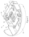
Figure 2 is a perspective view from above of theFig. 1 embodiment assembled in a dispenser; -
Figure 3 is a perspective view from above of theFig. 1 embodiment assembled in a dispenser, with certain parts removed for clarity; -
Figure 4 is a perspective view from above of theFig. 1 embodiment shown apart from the dispenser; and -
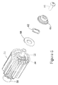
Figure 5 is a perspective view of the braking assembly of theFig. 1 embodiment. - In the drawings,
reference numeral 10 denotes a braking assembly according to the present invention. Thebraking assembly 10 is connected to a dispenser main housing (not shown). The main housing is configured to hold a supply of continuous feed material that is to be dispensed from the main housing. As recognized by those of ordinary skill in the art, the term "continuous feed material" includes paper, non-woven webs and other absorbent web material. This feed material might be wound in a roll or might be folded. The feed material might also be perforated or non-perforated. For the sake of convenience, the term "paper" is used below. However, the present invention is not limited to such material and each of the above noted materials and other feed materials known in the dispensing art are contemplated by the invention. - In the embodiment of
Figure 1 , thebraking assembly 10 includes a braking assembly housing 20 (seeFigure 2 ) having alower assembly housing 22 and anupper assembly housing 24. - A
first gear 30 is mounted in thebraking assembly housing 20. Thefirst gear 30 rotates about afirst axis 30A that extends longitudinally through a center of thefirst gear 30. Thefirst gear 30 includes arotation axle 32 that enables rotation of thefirst gear 30 about thefirst axis 30A inaxle support 26, 27 in thelower assembly housing 22. - The
lower assembly housing 22 also supports achassis 40 at chassis supports 28, 29. In a presently preferred embodiment, thechassis 40 is pivotally mounted in chassis supports 28, 29 via first andsecond chassis ends chassis 40 might also be mounted for linear movement, or might move by a combination of linear and pivoting motion. Thechassis 40 preferably includes an elongatemain body 42 having the first andsecond ends second arms 44, 46 extending substantially perpendicular to the elongatemain body 42. - A
second gear 50 is mounted on thechassis 40 between the first andsecond arms 44, 46. Thesecond gear 50 rotates about asecond axis 50A that is parallel to thefirst axis 30A. In a presently preferred embodiment, thechassis 40 pivots about athird axis 40A spaced apart from and parallel to thesecond axis 50A. Thesecond gear 50 hasteeth 55 that intermesh withteeth 35 of thefirst gear 30. An example of intermeshing teeth is disclosed in applicant's Patent No.6,089,401 - The
chassis 40 is configured to maintain the first andsecond gears second gears second gear 50 moving with thechassis 40. In a presently preferred embodiment,torsions springs second ends main body 42. The torsion springs 70, 75 bias thechassis 40 so as to maintain thefirst gear 30 and thesecond gear 50 adjacent to each other. Such configuration of thechassis 40 enables a distance between the gears to be changed while theteeth second gears - In a presently preferred embodiment, the configuration of the
axle support 26 is such that thefirst gear 30 is prevented from movement except in rotation. In this embodiment, the above-noted chassis configuration enables thesecond gear 50 to move with thechassis 40. However, the present invention contemplates that either or bothgears -
Figure 1 further shows abrake mechanism 60. Thebrake mechanism 60 controls the amount of force required to spin the gears. In a presently preferred embodiment, the brake mechanism varies the force required to spin thefirst gear 30 and is adjustable throughout from a relatively low to a relatively high amount of force such that thebrake mechanism 60 can accommodate paper product of various perforation strengths. Thebrake mechanism 60 can also be used to set a force such that the dispenser will dispense one segment of a continuous perforated sheet of paper or can be set to a lower force such that multiple segments can be removed without breaking the perforated material. The break force can be adjusted to meet the customers' requirements for consumption with multiple varieties of paper of various perforation strengths. - In the presently preferred embodiment, the
brake mechanism 60 includes awave washer 62 as seen inFigure 5 mounted over theaxle 32 of thefirst gear 30. Thewave washer 62 is held captivate between axle support 27 and ahub 64 on the end of theaxle 32. Thebrake mechanism 60 is held in place by ascrew 66 threaded into theaxle 32. A flat portion on the underside of the head of thescrew 66 abuts against thehub 64. - Adjusting a length of thread engagement on the
screw 66 causes thewave washer 62 to compress or allows it to expand. Increasing the thread engagement causes thewave washer 62 to compress and increases the axial force on thefirst gear 30, which in turn requires a higher force to rotate thefirst gear 30. Similarly, decreasing the screw engagement allows thewave washer 62 to expand and decreases the axial force on thefirst gear 30 allowing thefirst gear 30 to rotate more freely. - In other embodiments, the
wave washer 62 might be replaced by a spring or a piece ofresilient material 68 or any combination of these might be used such as would have the same effect of modifying the force required to rotate the gear through the compression and expansion of the resilient material. Additional components can be used to sandwich the resilient material to increase lubricity between the resilient material and the surfaces which hold the resilient material captive therebetween to reduce wear and extend the life of thebraking mechanism 60. - In the invention, the
braking mechanism 60 is connected to thefirst gear 30. Also, in other not claimed embodiments a brake mechanism could be installed on any other component in the "drive train" of thebraking assembly 10 so long as the end effect would result in controlling the amount of force required for rotating the gears. - In one embodiment of the invention, there is a
manual feed knob 80 that allows the user to advance the paper if the perforation breaks within the feed gears and there is no "tail" left showing for the next portion of paper. Themanual feed knob 80 might also be used to ease loading of the leading end of a fresh roll of material through thebraking assembly 10. In a presently preferred embodiment, themanual feed knob 80 turns along anaxis 80A perpendicular to the axes ofrotation second gears beveled gear 82 of themanual feed knob 80 and beveledgear 34 of thefirst gear 30. This setup allows a narrower profile for the dispenser as well as utilizing a gear ratio to optimize the force required to actuate themanual feed knob 80 for ergonomic factors. - In alternative embodiments, the feed knob might rotate along an axis parallel with the first and
second gears second gears manual feed knob 80 might be shaped in such a way that an end user can only gain an effective grip on the knob for turning in the prescribed direction. - As best seen in
Figures 3 and4 , thebraking assembly 10 might also include anti-reverse features. As recognized by those of ordinary skill in the art, thebraking assembly 10 of the present invention is designed to dispense paper from a paper source to an end user. To keep thebraking assembly 10 from being able to run counter to the designed direction, in a presently preferred embodiment, there is a gravity actuatedpawl 90 that rotates on anaxis 90A parallel to the axes ofrotation second gears Pawl 90 is arranged such that as material is being dispensed, thefirst gear 30 rotates away from thefree end 92 of thepawl 90. If thefirst gear 30 were to attempt to spin in a direction towards thepawl 90, thepawl 90 will engage one of theteeth 35 of thefirst gear 30 preventing thefirst gear 30 from further rotation in that direction. Although a pawl is described herein, nevertheless, as recognized by those of ordinary skill in the art, other mechanisms might be used to ensure that thebraking assembly 10 rotates in only one direction. - While the present invention has been described in connection with various preferred embodiments thereof, it is to be understood that those embodiments are provided merely to illustrate the invention, and that the invention might readily be varied within the scope of the appended claims.
Claims (13)
- A braking assembly (10) for a dispenser that dispenses a continuous feed material, said braking assembly comprising:a housing (20); a brake; a first gear (30) mounted in said housing (20), said first gear (30) being rotatable about a first axis (30A) ;a chassis (40) movably connected to said housing (20);a second gear (50) mounted on said chassis (40), said second gear (50) being rotatable about a second axis (50A) that is parallel to said first axis (30A);wherein teeth (35) of said first gear (30) and teeth (55) of said second gear (50) are configured to intermesh with each other and to allow continuous feed material to pass therethrough, said chassis (40) being configured to maintain said first and second gears (30, 50) adjacent to each other while enabling a distance between said first and second gears (30, 50) to be adjustable by the second gear (50) moving with the chassis (40); andcharacterized in that the brake (60) is is connected to said first gear (30) that controls an amount of force required to rotate said first gear (30).
- The braking assembly as claimed in claim 1, wherein the chassis (40) pivots about a third axis (40A) spaced apart from and parallel to said second axis (50A).
- The braking assembly as claimed in claim 2, wherein the chassis (40) includes an elongate main body portion (42) having first and second ends (41, 43), and first and second arms (44, 46) extending substantially perpendicular to the elongate main body portion (42), said second gear (50) being held between said first and second arms (44, 46).
- The braking assembly as claimed in claim 3, further comprising torsions springs (70, 75) connected to said first and second ends (41, 43) of said elongate main body portion (42) that bias the chassis (40) so as to maintain said first gear (30) and said second gear (50) adjacent to each other.
- The braking assembly as claimed in claim 1, wherein the brake (60) comprises a resilient member mounted on an axle (32) of said first gear (30) and a screw (66) threaded into said axle (32) of said first gear (30), wherein loosening and tightening of said screw (66) varies compression forces on the resilient member so as to adjust an amount of force required to rotate the first gear (30).
- The braking assembly as claimed in claim 5, further comprising means for limiting rotation of said first gear (30) in only one direction.
- The braking assembly as claimed in claim 6, wherein said means for limiting rotation of said first gear (30) in only one direction comprises an anti-reverse pawl (90) that engages a tooth (35) of said first gear (30).
- The braking assembly as claimed in claim 1, further comprising a manual feed knob (80) connected to one of said first and second gears (30, 50).
- The braking assembly as claimed in claim 8, wherein the manual feed knob (80) rotates about a feed knob axis (80A) that is perpendicular to said first axis (30A).
- The braking assembly as claimed in claim 1, wherein the brake (60) comprises a wave washer (62) mounted on an axle (32) of said first gear (30) and a screw (66) threaded into said axle (32) of said first gear (30), said screw (66) varying an amount of compression on said wave washer (62) so as to vary the amount of force required to rotate the first gear (30).
- The braking assembly as claimed in claim 1, wherein the brake (60) comprises one of a spring and a resilient material (68) configured to abut against an axle (32) of said first gear (30), compression or expansion of said spring or resilient material (68) varies the amount of force required to rotate the first gear (30).
- A dispenser for dispensing a continuous feed material, said dispenser comprising a braking assembly (10) according to any one of the preceding claims.
- The dispenser assembly as claimed in claim 12, further comprising a dispenser main housing, said main housing being connected to said housing (20) and being configured to hold a supply of continuous feed material that is to be fed through said first and second gears (30, 50) and be dispensed.
Applications Claiming Priority (2)
| Application Number | Priority Date | Filing Date | Title |
|---|---|---|---|
| US12/423,290 US8256700B2 (en) | 2009-04-14 | 2009-04-14 | Continuous feed material dispenser with adjustable brake |
| PCT/US2010/023267 WO2010120399A1 (en) | 2009-04-14 | 2010-02-05 | Continuous feed material dispenser with adjustable brake |
Publications (2)
| Publication Number | Publication Date |
|---|---|
| EP2418992A1 EP2418992A1 (en) | 2012-02-22 |
| EP2418992B1 true EP2418992B1 (en) | 2016-11-02 |
Family
ID=42173495
Family Applications (1)
| Application Number | Title | Priority Date | Filing Date |
|---|---|---|---|
| EP10706407.3A Not-in-force EP2418992B1 (en) | 2009-04-14 | 2010-02-05 | Continuous feed material dispenser with adjustable brake |
Country Status (8)
| Country | Link |
|---|---|
| US (3) | US8256700B2 (en) |
| EP (1) | EP2418992B1 (en) |
| CN (1) | CN102395307B (en) |
| AU (1) | AU2010236979A1 (en) |
| CO (1) | CO6450628A2 (en) |
| MX (1) | MX2011010496A (en) |
| RU (1) | RU2516799C2 (en) |
| WO (1) | WO2010120399A1 (en) |
Families Citing this family (18)
| Publication number | Priority date | Publication date | Assignee | Title |
|---|---|---|---|---|
| FR2907654B1 (en) | 2006-10-31 | 2010-01-29 | Georgia Pacific France | PROCESS, MANUFACTURING DEVICE AND ASSOCIATED ROLLS FORMED OF CUTTING SHEETS AND ALTERNATE PREDECOUPLES |
| US11297984B2 (en) | 2006-10-31 | 2022-04-12 | Gpcp Ip Holdings Llc | Automatic napkin dispenser |
| US10383489B2 (en) | 2012-02-10 | 2019-08-20 | Gpcp Ip Holdings Llc | Automatic napkin dispenser |
| RU2589609C1 (en) * | 2012-06-04 | 2016-07-10 | Ска Хайджин Продактс Аб | Dispensing unit and dispensing device |
| WO2014003618A1 (en) * | 2012-06-28 | 2014-01-03 | Sca Hygiene Products Ab | Dispensing unit and dispenser |
| CN104736029A (en) | 2012-10-26 | 2015-06-24 | Sca卫生用品公司 | Dispenser |
| ES2986780T3 (en) | 2012-10-26 | 2024-11-12 | Essity Hygiene & Health Ab | Separation and dispenser unit comprising a separation unit |
| US10390664B2 (en) * | 2012-10-26 | 2019-08-27 | Essity Hygiene And Health Aktiebolag | Separation unit and a dispenser comprising a separation unit |
| US9604811B2 (en) | 2013-10-01 | 2017-03-28 | Georgia-Pacific Consumer Products Lp | Automatic paper product dispenser with data collection and method |
| WO2015167371A1 (en) | 2014-04-28 | 2015-11-05 | Sca Hygiene Products Ab | Dispenser |
| US10334996B2 (en) | 2017-01-26 | 2019-07-02 | Essity Hygiene And Health Aktiebolag | Paper dispenser and related methods |
| CN110494070A (en) | 2017-05-10 | 2019-11-22 | Gpcp知识产权控股有限责任公司 | Automatic paper product dispenser and associated method |
| US10850938B2 (en) | 2017-10-09 | 2020-12-01 | Gpcp Ip Holdings Llc | Mechanical sheet product dispenser |
| US11224314B2 (en) | 2019-05-31 | 2022-01-18 | San Jamar, Inc. | Web material center-pull dispenser assembly |
| USD984824S1 (en) | 2019-05-31 | 2023-05-02 | San Jamar, Inc. | Center pull-through dispenser |
| CA3098081C (en) | 2019-11-22 | 2026-02-03 | Gpcp Ip Holdings Llc | Frictional features for rolled sheet product dispensers |
| CN112847406A (en) * | 2021-02-24 | 2021-05-28 | 安徽云超智能科技有限公司 | Intelligent servo robot |
| CN115704522A (en) * | 2021-08-11 | 2023-02-17 | 苏州佳世达电通有限公司 | Lifting support mechanism and display device with adjustable lifting height |
Citations (1)
| Publication number | Priority date | Publication date | Assignee | Title |
|---|---|---|---|---|
| WO1997026818A1 (en) * | 1996-01-23 | 1997-07-31 | Sca Hygiene Paper Ab | Braking arrangement for dispensers of continuous material |
Family Cites Families (12)
| Publication number | Priority date | Publication date | Assignee | Title |
|---|---|---|---|---|
| US1746582A (en) * | 1926-02-25 | 1930-02-11 | J Ray Bennett | Wrapping-paper-feed device |
| GB478551A (en) | 1936-03-30 | 1938-01-20 | Zdenek Jiskra | Improvements in date indicators |
| GB487551A (en) | 1936-08-08 | 1938-06-22 | Friedrich Wiederrecht | Toilet paper holder |
| US5118011A (en) | 1990-12-05 | 1992-06-02 | Oatey Co. | Food roller dispenser |
| JPH04310947A (en) * | 1991-04-09 | 1992-11-02 | Fuji Photo Film Co Ltd | Cartridge for photographic film |
| US5452832A (en) | 1993-04-06 | 1995-09-26 | Qts S.R.L. | Automatic dispenser for paper towels severable from a continuous roll |
| GB9412076D0 (en) | 1994-06-16 | 1994-08-03 | Wyant And Company Limited | Paper towel dispenser for dispensing towelling from inside diameter of roll |
| US6510964B2 (en) | 2000-11-13 | 2003-01-28 | Englewood Ventures, Inc. | Center-pull sheet material dispenser |
| US6695247B2 (en) | 2001-10-10 | 2004-02-24 | Sca Hygiene Products Ab | Holder for a paper roll with axial dispensing of the paper in the roll |
| TWI231199B (en) * | 2002-09-12 | 2005-04-21 | Kimberly Clark Co | Dispenser for rolled paper |
| RU2354278C2 (en) * | 2004-04-01 | 2009-05-10 | Морис ГРАНЖЕ | Batching device locking mechanism, material roll with its end stopper and method of feeding material roll into proposed locking mechanism |
| US7347134B2 (en) | 2004-09-29 | 2008-03-25 | Kimberly-Clark Worldwide, Inc. | No touch dispenser for sheet material with automatic advance |
-
2009
- 2009-04-14 US US12/423,290 patent/US8256700B2/en not_active Expired - Fee Related
-
2010
- 2010-02-05 CN CN201080016678.9A patent/CN102395307B/en not_active Expired - Fee Related
- 2010-02-05 RU RU2011145975/12A patent/RU2516799C2/en not_active IP Right Cessation
- 2010-02-05 AU AU2010236979A patent/AU2010236979A1/en not_active Abandoned
- 2010-02-05 MX MX2011010496A patent/MX2011010496A/en not_active Application Discontinuation
- 2010-02-05 WO PCT/US2010/023267 patent/WO2010120399A1/en not_active Ceased
- 2010-02-05 EP EP10706407.3A patent/EP2418992B1/en not_active Not-in-force
-
2011
- 2011-11-10 CO CO11152725A patent/CO6450628A2/en active IP Right Grant
-
2012
- 2012-05-15 US US13/471,687 patent/US8616486B2/en not_active Expired - Fee Related
-
2013
- 2013-11-04 US US14/071,161 patent/US9499369B2/en not_active Expired - Fee Related
Patent Citations (1)
| Publication number | Priority date | Publication date | Assignee | Title |
|---|---|---|---|---|
| WO1997026818A1 (en) * | 1996-01-23 | 1997-07-31 | Sca Hygiene Paper Ab | Braking arrangement for dispensers of continuous material |
Also Published As
| Publication number | Publication date |
|---|---|
| RU2516799C2 (en) | 2014-05-20 |
| CN102395307A (en) | 2012-03-28 |
| EP2418992A1 (en) | 2012-02-22 |
| MX2011010496A (en) | 2012-06-27 |
| WO2010120399A1 (en) | 2010-10-21 |
| US20140061355A1 (en) | 2014-03-06 |
| RU2011145975A (en) | 2013-05-20 |
| AU2010236979A1 (en) | 2011-10-27 |
| CN102395307B (en) | 2014-09-17 |
| US20100258579A1 (en) | 2010-10-14 |
| US8616486B2 (en) | 2013-12-31 |
| US8256700B2 (en) | 2012-09-04 |
| US20120223175A1 (en) | 2012-09-06 |
| US9499369B2 (en) | 2016-11-22 |
| CO6450628A2 (en) | 2012-05-31 |
Similar Documents
| Publication | Publication Date | Title |
|---|---|---|
| US8256700B2 (en) | Continuous feed material dispenser with adjustable brake | |
| RU2484753C2 (en) | Sheets dispenser | |
| US8899508B2 (en) | Dispenser for roll of absorbent paper tissue or nonwoven material | |
| US11889955B2 (en) | Dispenser for rolled sheet materials | |
| CA2148727C (en) | Paper towel dispenser for dispensing towelling from inside diameter of roll | |
| JP2714481B2 (en) | Method and apparatus for dispensing flexible sheet material | |
| US9795258B2 (en) | Dispenser apparatus with damper for dispensing paper toweling | |
| US10045669B2 (en) | Rolled product dispenser | |
| US20130161346A1 (en) | Dispenser | |
| RU2621663C2 (en) | Dispensing device for sheet products | |
| US20050223860A1 (en) | Adjustable cutter | |
| KR102497124B1 (en) | sheet product divider | |
| DE69806932T2 (en) | DISPENSER OF WIPING MATERIAL FOR DISPENSING IN FOLDED FORM | |
| US6161795A (en) | Surface unwind jumbo roll tissue dispenser | |
| US20200329924A1 (en) | Spindle assembly for sheet product dispensers | |
| US6554158B2 (en) | Apparatus for dispensing rolled sheet material | |
| CA2641027A1 (en) | Articulated nip in a dispenser apparatus | |
| JP2005538774A (en) | Dispensing device for roll paper | |
| KR102586796B1 (en) | sheet product divider | |
| MXPA01005739A (en) | Surface unwind jumbo roll tissue dispenser |
Legal Events
| Date | Code | Title | Description |
|---|---|---|---|
| PUAI | Public reference made under article 153(3) epc to a published international application that has entered the european phase |
Free format text: ORIGINAL CODE: 0009012 |
|
| 17P | Request for examination filed |
Effective date: 20110922 |
|
| AK | Designated contracting states |
Kind code of ref document: A1 Designated state(s): AT BE BG CH CY CZ DE DK EE ES FI FR GB GR HR HU IE IS IT LI LT LU LV MC MK MT NL NO PL PT RO SE SI SK SM TR |
|
| DAX | Request for extension of the european patent (deleted) | ||
| 17Q | First examination report despatched |
Effective date: 20150126 |
|
| GRAP | Despatch of communication of intention to grant a patent |
Free format text: ORIGINAL CODE: EPIDOSNIGR1 |
|
| INTG | Intention to grant announced |
Effective date: 20160301 |
|
| GRAP | Despatch of communication of intention to grant a patent |
Free format text: ORIGINAL CODE: EPIDOSNIGR1 |
|
| INTG | Intention to grant announced |
Effective date: 20160519 |
|
| GRAS | Grant fee paid |
Free format text: ORIGINAL CODE: EPIDOSNIGR3 |
|
| GRAA | (expected) grant |
Free format text: ORIGINAL CODE: 0009210 |
|
| AK | Designated contracting states |
Kind code of ref document: B1 Designated state(s): AT BE BG CH CY CZ DE DK EE ES FI FR GB GR HR HU IE IS IT LI LT LU LV MC MK MT NL NO PL PT RO SE SI SK SM TR |
|
| REG | Reference to a national code |
Ref country code: GB Ref legal event code: FG4D |
|
| REG | Reference to a national code |
Ref country code: AT Ref legal event code: REF Ref document number: 840930 Country of ref document: AT Kind code of ref document: T Effective date: 20161115 Ref country code: CH Ref legal event code: EP |
|
| REG | Reference to a national code |
Ref country code: IE Ref legal event code: FG4D |
|
| REG | Reference to a national code |
Ref country code: DE Ref legal event code: R096 Ref document number: 602010037609 Country of ref document: DE |
|
| REG | Reference to a national code |
Ref country code: SE Ref legal event code: TRGR |
|
| REG | Reference to a national code |
Ref country code: FR Ref legal event code: PLFP Year of fee payment: 8 |
|
| PG25 | Lapsed in a contracting state [announced via postgrant information from national office to epo] |
Ref country code: LV Free format text: LAPSE BECAUSE OF FAILURE TO SUBMIT A TRANSLATION OF THE DESCRIPTION OR TO PAY THE FEE WITHIN THE PRESCRIBED TIME-LIMIT Effective date: 20161102 |
|
| REG | Reference to a national code |
Ref country code: NL Ref legal event code: MP Effective date: 20161102 |
|
| REG | Reference to a national code |
Ref country code: LT Ref legal event code: MG4D |
|
| REG | Reference to a national code |
Ref country code: AT Ref legal event code: MK05 Ref document number: 840930 Country of ref document: AT Kind code of ref document: T Effective date: 20161102 |
|
| PG25 | Lapsed in a contracting state [announced via postgrant information from national office to epo] |
Ref country code: LT Free format text: LAPSE BECAUSE OF FAILURE TO SUBMIT A TRANSLATION OF THE DESCRIPTION OR TO PAY THE FEE WITHIN THE PRESCRIBED TIME-LIMIT Effective date: 20161102 Ref country code: NL Free format text: LAPSE BECAUSE OF FAILURE TO SUBMIT A TRANSLATION OF THE DESCRIPTION OR TO PAY THE FEE WITHIN THE PRESCRIBED TIME-LIMIT Effective date: 20161102 Ref country code: NO Free format text: LAPSE BECAUSE OF FAILURE TO SUBMIT A TRANSLATION OF THE DESCRIPTION OR TO PAY THE FEE WITHIN THE PRESCRIBED TIME-LIMIT Effective date: 20170202 Ref country code: GR Free format text: LAPSE BECAUSE OF FAILURE TO SUBMIT A TRANSLATION OF THE DESCRIPTION OR TO PAY THE FEE WITHIN THE PRESCRIBED TIME-LIMIT Effective date: 20170203 |
|
| PG25 | Lapsed in a contracting state [announced via postgrant information from national office to epo] |
Ref country code: HR Free format text: LAPSE BECAUSE OF FAILURE TO SUBMIT A TRANSLATION OF THE DESCRIPTION OR TO PAY THE FEE WITHIN THE PRESCRIBED TIME-LIMIT Effective date: 20161102 Ref country code: IS Free format text: LAPSE BECAUSE OF FAILURE TO SUBMIT A TRANSLATION OF THE DESCRIPTION OR TO PAY THE FEE WITHIN THE PRESCRIBED TIME-LIMIT Effective date: 20170302 Ref country code: PT Free format text: LAPSE BECAUSE OF FAILURE TO SUBMIT A TRANSLATION OF THE DESCRIPTION OR TO PAY THE FEE WITHIN THE PRESCRIBED TIME-LIMIT Effective date: 20170302 Ref country code: AT Free format text: LAPSE BECAUSE OF FAILURE TO SUBMIT A TRANSLATION OF THE DESCRIPTION OR TO PAY THE FEE WITHIN THE PRESCRIBED TIME-LIMIT Effective date: 20161102 Ref country code: PL Free format text: LAPSE BECAUSE OF FAILURE TO SUBMIT A TRANSLATION OF THE DESCRIPTION OR TO PAY THE FEE WITHIN THE PRESCRIBED TIME-LIMIT Effective date: 20161102 Ref country code: ES Free format text: LAPSE BECAUSE OF FAILURE TO SUBMIT A TRANSLATION OF THE DESCRIPTION OR TO PAY THE FEE WITHIN THE PRESCRIBED TIME-LIMIT Effective date: 20161102 Ref country code: BE Free format text: LAPSE BECAUSE OF NON-PAYMENT OF DUE FEES Effective date: 20170228 |
|
| PG25 | Lapsed in a contracting state [announced via postgrant information from national office to epo] |
Ref country code: RO Free format text: LAPSE BECAUSE OF FAILURE TO SUBMIT A TRANSLATION OF THE DESCRIPTION OR TO PAY THE FEE WITHIN THE PRESCRIBED TIME-LIMIT Effective date: 20161102 Ref country code: DK Free format text: LAPSE BECAUSE OF FAILURE TO SUBMIT A TRANSLATION OF THE DESCRIPTION OR TO PAY THE FEE WITHIN THE PRESCRIBED TIME-LIMIT Effective date: 20161102 Ref country code: EE Free format text: LAPSE BECAUSE OF FAILURE TO SUBMIT A TRANSLATION OF THE DESCRIPTION OR TO PAY THE FEE WITHIN THE PRESCRIBED TIME-LIMIT Effective date: 20161102 Ref country code: CZ Free format text: LAPSE BECAUSE OF FAILURE TO SUBMIT A TRANSLATION OF THE DESCRIPTION OR TO PAY THE FEE WITHIN THE PRESCRIBED TIME-LIMIT Effective date: 20161102 Ref country code: SK Free format text: LAPSE BECAUSE OF FAILURE TO SUBMIT A TRANSLATION OF THE DESCRIPTION OR TO PAY THE FEE WITHIN THE PRESCRIBED TIME-LIMIT Effective date: 20161102 |
|
| REG | Reference to a national code |
Ref country code: DE Ref legal event code: R097 Ref document number: 602010037609 Country of ref document: DE |
|
| PG25 | Lapsed in a contracting state [announced via postgrant information from national office to epo] |
Ref country code: BG Free format text: LAPSE BECAUSE OF FAILURE TO SUBMIT A TRANSLATION OF THE DESCRIPTION OR TO PAY THE FEE WITHIN THE PRESCRIBED TIME-LIMIT Effective date: 20170202 Ref country code: SM Free format text: LAPSE BECAUSE OF FAILURE TO SUBMIT A TRANSLATION OF THE DESCRIPTION OR TO PAY THE FEE WITHIN THE PRESCRIBED TIME-LIMIT Effective date: 20161102 Ref country code: IT Free format text: LAPSE BECAUSE OF FAILURE TO SUBMIT A TRANSLATION OF THE DESCRIPTION OR TO PAY THE FEE WITHIN THE PRESCRIBED TIME-LIMIT Effective date: 20161102 Ref country code: BE Free format text: LAPSE BECAUSE OF FAILURE TO SUBMIT A TRANSLATION OF THE DESCRIPTION OR TO PAY THE FEE WITHIN THE PRESCRIBED TIME-LIMIT Effective date: 20161102 |
|
| PLBE | No opposition filed within time limit |
Free format text: ORIGINAL CODE: 0009261 |
|
| STAA | Information on the status of an ep patent application or granted ep patent |
Free format text: STATUS: NO OPPOSITION FILED WITHIN TIME LIMIT |
|
| PG25 | Lapsed in a contracting state [announced via postgrant information from national office to epo] |
Ref country code: MC Free format text: LAPSE BECAUSE OF FAILURE TO SUBMIT A TRANSLATION OF THE DESCRIPTION OR TO PAY THE FEE WITHIN THE PRESCRIBED TIME-LIMIT Effective date: 20161102 |
|
| REG | Reference to a national code |
Ref country code: CH Ref legal event code: PL |
|
| 26N | No opposition filed |
Effective date: 20170803 |
|
| PG25 | Lapsed in a contracting state [announced via postgrant information from national office to epo] |
Ref country code: LI Free format text: LAPSE BECAUSE OF NON-PAYMENT OF DUE FEES Effective date: 20170228 Ref country code: CH Free format text: LAPSE BECAUSE OF NON-PAYMENT OF DUE FEES Effective date: 20170228 |
|
| REG | Reference to a national code |
Ref country code: IE Ref legal event code: MM4A |
|
| PG25 | Lapsed in a contracting state [announced via postgrant information from national office to epo] |
Ref country code: SI Free format text: LAPSE BECAUSE OF FAILURE TO SUBMIT A TRANSLATION OF THE DESCRIPTION OR TO PAY THE FEE WITHIN THE PRESCRIBED TIME-LIMIT Effective date: 20161102 |
|
| PG25 | Lapsed in a contracting state [announced via postgrant information from national office to epo] |
Ref country code: LU Free format text: LAPSE BECAUSE OF NON-PAYMENT OF DUE FEES Effective date: 20170205 |
|
| REG | Reference to a national code |
Ref country code: FR Ref legal event code: PLFP Year of fee payment: 9 |
|
| PG25 | Lapsed in a contracting state [announced via postgrant information from national office to epo] |
Ref country code: IE Free format text: LAPSE BECAUSE OF NON-PAYMENT OF DUE FEES Effective date: 20170205 |
|
| PGFP | Annual fee paid to national office [announced via postgrant information from national office to epo] |
Ref country code: FI Payment date: 20180216 Year of fee payment: 9 Ref country code: DE Payment date: 20180222 Year of fee payment: 9 Ref country code: GB Payment date: 20180221 Year of fee payment: 9 |
|
| PGFP | Annual fee paid to national office [announced via postgrant information from national office to epo] |
Ref country code: FR Payment date: 20180221 Year of fee payment: 9 Ref country code: SE Payment date: 20180123 Year of fee payment: 9 |
|
| PG25 | Lapsed in a contracting state [announced via postgrant information from national office to epo] |
Ref country code: MT Free format text: LAPSE BECAUSE OF NON-PAYMENT OF DUE FEES Effective date: 20170205 |
|
| PG25 | Lapsed in a contracting state [announced via postgrant information from national office to epo] |
Ref country code: HU Free format text: LAPSE BECAUSE OF FAILURE TO SUBMIT A TRANSLATION OF THE DESCRIPTION OR TO PAY THE FEE WITHIN THE PRESCRIBED TIME-LIMIT; INVALID AB INITIO Effective date: 20100205 |
|
| REG | Reference to a national code |
Ref country code: DE Ref legal event code: R119 Ref document number: 602010037609 Country of ref document: DE |
|
| REG | Reference to a national code |
Ref country code: SE Ref legal event code: EUG |
|
| GBPC | Gb: european patent ceased through non-payment of renewal fee |
Effective date: 20190205 |
|
| PG25 | Lapsed in a contracting state [announced via postgrant information from national office to epo] |
Ref country code: SE Free format text: LAPSE BECAUSE OF NON-PAYMENT OF DUE FEES Effective date: 20190206 Ref country code: FI Free format text: LAPSE BECAUSE OF NON-PAYMENT OF DUE FEES Effective date: 20190205 Ref country code: CY Free format text: LAPSE BECAUSE OF NON-PAYMENT OF DUE FEES Effective date: 20161102 |
|
| PG25 | Lapsed in a contracting state [announced via postgrant information from national office to epo] |
Ref country code: MK Free format text: LAPSE BECAUSE OF FAILURE TO SUBMIT A TRANSLATION OF THE DESCRIPTION OR TO PAY THE FEE WITHIN THE PRESCRIBED TIME-LIMIT Effective date: 20161102 |
|
| PG25 | Lapsed in a contracting state [announced via postgrant information from national office to epo] |
Ref country code: DE Free format text: LAPSE BECAUSE OF NON-PAYMENT OF DUE FEES Effective date: 20190903 Ref country code: GB Free format text: LAPSE BECAUSE OF NON-PAYMENT OF DUE FEES Effective date: 20190205 |
|
| PG25 | Lapsed in a contracting state [announced via postgrant information from national office to epo] |
Ref country code: FR Free format text: LAPSE BECAUSE OF NON-PAYMENT OF DUE FEES Effective date: 20190228 |
|
| PG25 | Lapsed in a contracting state [announced via postgrant information from national office to epo] |
Ref country code: TR Free format text: LAPSE BECAUSE OF FAILURE TO SUBMIT A TRANSLATION OF THE DESCRIPTION OR TO PAY THE FEE WITHIN THE PRESCRIBED TIME-LIMIT Effective date: 20161102 |