EP2418766A1 - Frequency error estimation immune to FM clicks - Google Patents
Frequency error estimation immune to FM clicks Download PDFInfo
- Publication number
- EP2418766A1 EP2418766A1 EP11175907A EP11175907A EP2418766A1 EP 2418766 A1 EP2418766 A1 EP 2418766A1 EP 11175907 A EP11175907 A EP 11175907A EP 11175907 A EP11175907 A EP 11175907A EP 2418766 A1 EP2418766 A1 EP 2418766A1
- Authority
- EP
- European Patent Office
- Prior art keywords
- signal
- sample
- phase
- frequency
- signal sample
- Prior art date
- Legal status (The legal status is an assumption and is not a legal conclusion. Google has not performed a legal analysis and makes no representation as to the accuracy of the status listed.)
- Granted
Links
- 238000000034 method Methods 0.000 claims description 42
- 238000000926 separation method Methods 0.000 claims description 19
- 238000004891 communication Methods 0.000 description 7
- 238000001914 filtration Methods 0.000 description 7
- 230000008901 benefit Effects 0.000 description 4
- 238000005070 sampling Methods 0.000 description 4
- 238000013459 approach Methods 0.000 description 3
- 238000006243 chemical reaction Methods 0.000 description 3
- 238000001514 detection method Methods 0.000 description 3
- 238000004590 computer program Methods 0.000 description 2
- 238000010586 diagram Methods 0.000 description 2
- 239000000463 material Substances 0.000 description 2
- 238000012545 processing Methods 0.000 description 2
- 238000012935 Averaging Methods 0.000 description 1
- 206010035148 Plague Diseases 0.000 description 1
- 241000607479 Yersinia pestis Species 0.000 description 1
- 239000000654 additive Substances 0.000 description 1
- 230000000996 additive effect Effects 0.000 description 1
- 238000010420 art technique Methods 0.000 description 1
- 238000007796 conventional method Methods 0.000 description 1
- 238000012937 correction Methods 0.000 description 1
- 239000013078 crystal Substances 0.000 description 1
- 238000013500 data storage Methods 0.000 description 1
- 230000003111 delayed effect Effects 0.000 description 1
- 238000013461 design Methods 0.000 description 1
- 230000000694 effects Effects 0.000 description 1
- 238000005562 fading Methods 0.000 description 1
- 230000003287 optical effect Effects 0.000 description 1
- 230000003252 repetitive effect Effects 0.000 description 1
- 239000004065 semiconductor Substances 0.000 description 1
- 230000035945 sensitivity Effects 0.000 description 1
- 238000006467 substitution reaction Methods 0.000 description 1
Images


Classifications
-
- H—ELECTRICITY
- H03—ELECTRONIC CIRCUITRY
- H03D—DEMODULATION OR TRANSFERENCE OF MODULATION FROM ONE CARRIER TO ANOTHER
- H03D3/00—Demodulation of angle-, frequency- or phase- modulated oscillations
- H03D3/001—Details of arrangements applicable to more than one type of frequency demodulator
- H03D3/003—Arrangements for reducing frequency deviation, e.g. by negative frequency feedback
-
- H—ELECTRICITY
- H03—ELECTRONIC CIRCUITRY
- H03D—DEMODULATION OR TRANSFERENCE OF MODULATION FROM ONE CARRIER TO ANOTHER
- H03D3/00—Demodulation of angle-, frequency- or phase- modulated oscillations
- H03D3/02—Demodulation of angle-, frequency- or phase- modulated oscillations by detecting phase difference between two signals obtained from input signal
Definitions
- the present disclosure generally relates to communication systems, and more particularly to estimating the frequency error on a received signal that is immune to FM clicks.
- FM and FSK radio systems A problem that plagues almost all frequency modulated (FM) and frequency shift keyed (FSK) radio systems are the FM "clicks” and “pops” that occur at low signal levels, such as when the channel signal to noise ratio (SNR) gets to 10 dB or less. "Clicks” and “pops” are generally understood to be noise events that enhance the additive noise generated in the demodulation process. At low input signal-to-noise ratios, the resulting noise enhancements can become the dominant noise source.
- SNR channel signal to noise ratio
- Frequency demodulation is normally accomplished by comparing the phase of a signal at one instant in time to the phase of the signal at an adjacent instant.
- the frequency of a signal is the change in phase divided by the change in time. Modulation on the signal will push the phase back and forth. By detecting these changes, FM is demodulated.
- the FM signal can generally be pictured as a constant-amplitude vector that pivots up and down. Noise pushes the signal vector about, but the average location of the vector remains the same, so post-demodulation filtering can remove most of the effects of noise.
- the signal gets weak, for example at around 10 dB SNR, there is a possibility of noise making it appear as though the vector took a 360 degree spin about the origin, which it did not.
- This 2- ⁇ (pi) rotation causes an impulse in the demodulated output waveform, which is generally in the form of a large pulse having a frequency content extending over a wide bandwidth including DC. Filtering the signal merely spreads the pulse out over multiple samples. At modulation indexes typical of narrowband data radios, the actual phase never moves much more than 45 degrees in a bit time. So while post-detection filtering averages out regular FM noise, click or pop-noise does not benefit from any amount of filtering. It is common for an FSK modem's performance to be surprisingly poor, even though the post detection SNR is quite good, because the predetection SNR is under 10 dB, resulting in clicks.
- frequency error relative to the symbol rate is significant.
- the phase will move approximately 38 degrees per bit due to the frequency error alone. This error must be accounted for.
- One approach is to estimate the frequency error with a conventional limiter-discriminator followed by a filter to average the waveform over a few dozen bit times.
- clicks will cause an error in the frequency estimate if we try to operate below a 10dB SNR. Since certain wireless devices with optimized forward error correction are capable of performing with channel SNR below 0 dB, it would be advantageous to keep the frequency estimation technique from limiting the sensitivity.
- phase locked loop PLL
- threshold extension a phase locked loop demodulator
- the exemplary embodiments overcome one or more of the above or other disadvantages known in the art.
- the apparatus includes a receiver for receiving a frequency modulated (FM) signal, and a processor for demodulating the received signal and estimating a frequency error, wherein the processor is configured to determine phase variations of the received FM signal by comparing a phase of a first signal sample to a phase of a second signal sample, wherein the first signal sample and the second signal sample are separated in time by more than one sample.
- FM frequency modulated
- the disclosed embodiments are directed to a method of estimating frequency error on a received frequency modulated (FM) signal that is immune to FM clicks.
- the method includes receiving the frequency modulated signal in a receiver system, demodulating the received signal including comparing a phase of a first signal sample to a phase of a second signal sample to determine a phase error; where the first signal sample and the second signal sample are separated in time by more than one sample, and providing an estimate of the frequency error on the received signal that is immune to FM clicks.
- a communication system incorporating aspects of the disclosed embodiments is generally designated by reference numeral 100.
- the aspects of the disclosed embodiments are generally directed to estimating frequency error on a received signal that is generally immune to the FM "clicks” and “pops” that typically limit the weak signal performance in FM and FSK systems.
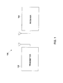
- the communication system 100 shown in Fig. 1 generally comprises a transmitter 102 and a receiver 104.
- the system 100 is a wireless system that provides long distance communications of data over licensed radio bands, such as for example, radio bands in the frequency range of approximately 200 MHz to 900 MHz.
- the radio system incorporating aspects of the present disclosure can be operated in any suitable radio band.
- One example of a communication system 100 is the Digital Energy SD series Long Range IP/Ethernet & Serial MDS SD2, MDS SD4 and MDS SD9, manufactured by GE.
- the effectiveness of a receiver 104 can be limited when a transmitted signal is degraded by any one of a number of factors including for example, obstructions, interference, fading and noise.
- a received signal becomes small, it can cause a decrease in the signal-to-noise ratio of the radio receiver.
- the phase variations of the received signal can generate repetitive audio disturbances, generally referred to herein as FM clicks.
- the system 200 of Fig. 2 is one of the more common methods of frequency demodulation in an analog approach.
- the system 200 of Fig. 2 generally comprises amplifiers and mixers 204 for initially processing the received signal 202, as well as frequency conversion.
- a filter 206 passes the desired frequency while rejecting adjacent channel signals, and quadrature detector 208 can be used to recover the baseband signal.
- the frequency error can be estimated with a conventional limiter-discriminator followed by a filter, such as filter 210 to average the waveform over a few dozen-bit times and generate the frequency estimate 212.
- the resulting FM clicks will cause an error in the frequency estimate.
- post detection filtering may average out regular FM noise, the FM click or pop noise does not benefit from such filtering.
- digital data is typically transmitted in bursts, where each burst comprises a pre-defined number of data bits. While digital communication systems can improve audio quality using digital data and audio processing, the noise resulting from FM clicks may prevent the digital demodulation process entirely.
- Fig. 3 illustrates one embodiment of a receiver and demodulation system 300 incorporating aspects of the disclosed embodiments.
- the system 300 generally includes a demodulator 310 and a processor 320.
- the processor 320 is generally configured to process the received signal 302 and produce a frequency estimate 325 that is free of, or essentially immune from the issue of FM clicks.
- the processor 320 accomplishes this by comparing the phases of signal samples that are significantly separated in time, rather than adjacent signals, to demodulate the received signal 302.
- the processor 320 comprises a field programmable gate array (FPGA) or Digital Signal Processor (DSP) 320.
- the system 300 can include other suitable components that might be typically including for performing functions and operations such as frequency conversion, filtering, rate conversion and automatic gain control. For purposes of the explanation herein, theses components are not included in the accompanying figures.
- the demodulator 310 shown in Fig. 3 generally comprises a quadrature demodulator that is configured to demodulate the received signal 302 to produce In-phase (I) and Quadrature (Q) baseband signals.
- the demodulator 310 includes a quadrature mixer and an Analog to Digital (A to D) converter.
- the demodulator 310 samples the received signal and a quadrature (90-degree shifted) version of the received signal.
- the outputs are digital representations of those two signals, typically using between 8 and 24 bits to represent the instantaneous voltage of each signal.
- the channel filter 321 performs a mathematical operation on the digital signals to pass the desired on-channel signal and rejects signals and noise in neighboring channels.
- the phase estimator 322 operates on the two signals doing what generally amounts to an Arc-Tangent lookup. From the instantaneous value of I and Q, the phase comparator 323 determines the phase of the signal.
- the frequency can be determined since the frequency is the change in phase divided by the change in time.
- the sample time is predetermined based on various system requirements, and is fixed.
- the systems of the prior art compare each sample with the preceding sample to determine the phase change, the phase difference being proportional to the received frequency.
- the aspects of the disclosed embodiments compare each phase sample with a sample that is several time steps removed.
- the filter 324 averages the result. When the received signal 302 is weak, each frequency estimate made by the phase comparison has a random error in it due to noise. The filter 324 reduces these errors by averaging them out.
- the processor 320 is generally configured to compare the phase of samples of the received signal 302 that are significantly separated in time from one another.
- the time separation between samples is large relative to the bandwidth of the received signal 302 being processed.
- the sampling rate of a signal is at a much smaller interval, such as twice the frequency of the signal, also referred to as the "Nyquist rate.”
- the aspects of the disclosed embodiments utilize a sampling rate that is generally a fraction of the Nyquist rate.
- the sampling rate is approximately 1/5 th to 1/10 th the Nyquist rate.
- the sampling rate can be any fraction of the Nyquist rate, other than including 1/5 th to 1/10 th .
- the larger the time separation between samples being compared the more immune the resulting signal 325 is from FM clicks.
- crystal oscillators determine the frequency accuracy of the transmitter 102 and receiver 104 in a communication system 100.
- the manufacturer of the oscillator specifies a maximum error over a range of temperatures.
- the GE-MDS SD series radio uses an oscillator guaranteed to be within 1 part per million from ⁇ 40 to +60 degrees C.
- the frequency When a 500 MHz signal is transmitted, the frequency could be 500 Hz off (1 millionth of 500 MHz).
- the sample clock within the processor 320 operates at approximately 30.722 ⁇ sec, but using samples at that rate results in FM clicks. Instead, in accordance with the aspects of the disclosed embodiments, samples are compared that are separated by up to 500 ⁇ sec.
- the received signal is demodulated by taking the angle of the signal multiplied by the conjugate of a delayed sample. This allows for a comparison of the phase of the two samples.
- the phase of the two samples are separated by one full cycle of a preamble tone and then compared. This allows the phase change due to modulation to cancel out. For each phase comparison, the modulation vector remains substantially stationary, and any remaining phase difference is due to either frequency error or noise. By solving for frequency error using samples separated in time, the FM clicks are no longer significant.
- the received signal appears to have a 360- degree phase rotation at one spot in an approximately the middle.
- the resulting demodulated signal is:
- the demodulation method of the disclosed embodiments using the phase difference between samples that are significant separated in time, in this example 16-bits apart, provides the following demodulated signal:
- the peak is +/-3.14/128 or +/1 0.0245 radians per 16 samples. This is the equivalent of +/- 0.0015 radians per sample.
- the disturbance creates a pair of glitches, which cancel each other out. Additionally, the glitches are small because the phase change is considered to have occurred over 16 sample times, or bits, instead of one, where the phase change of adjacent samples is measured.
- Fig. 4 illustrates a comparison of the waveforms resulting from the demodulation of signal 302 using different modulation techniques.
- the top graph 400 shows the demodulated output signal waveform 402 using the conventional prior art technique of comparing the phase change of adjacent samples.
- the bottom graph 410 illustrates the demodulated output signal waveform 412 resulting from using the phase change of samples significantly separated in time in accordance with the aspects of the disclosed embodiments.
- Waveform 402 includes a frequency offset spike 404, having an amplitude of approximately 300 Hz.
- waveform 412 does not include any spikes or noise clicks. Rather, the average frequency offset is approximately 0.
- the sample separation is 16 sample times. Any glitches or spikes that do occur are small due to the sample separation, and tend to cancel themselves out.
- Fig. 5 illustrates the exemplary waveforms resulting from the estimation of the frequency error of a 100 Hz off-frequency preamble signal received at 6 dB Eb/No.
- the upper graph 500 illustrates the waveform 502 resulting using a conventional method of determining frequency.
- the estimation results in FM clicks, shown as spikes or glitches 504, 506 and 508.
- the lower graph 510 illustrates the waveform 512 resulting from demodulating the received signal by measuring the phase differences of samples significantly separated in time, in accordance with the aspects of the disclosed embodiments.
- the waveform 512 does not include any spikes or glitches, and is substantially immune to the FM clicks that can limit frequency estimation and radio performance at weak signal levels.
- the graphs of Figs. 4 and 5 illustrate the advantages of the disclosed embodiments, since there are no pulses or clicks in either waveform 412 or 512.
- the pulses and clicks are present.
- the graph in Fig. 6 illustrates a waveform 602 of the unwrapped angle of the RF signal that resulted in the demodulated waveforms shown in Fig. 5 .
- the vertical axis 604 is the phase of the received signal in radians.
- the line of the waveform 602 is substantially diagonal because the frequency error is -100 Hz, so the phase of each sample is slightly less than the previous one.
- noise on the signal makes it appear as though the phase took a 2- ⁇ jump (6.28 radians).
- the prior art FM demodulation techniques produce a click in each of those occurrences, as shown by waveform 502 in graph 500, but using the system of the disclosed embodiments, the resulting demodulated signal is immune from any clicks, as shown by the waveform 512 in graph 510.
- the aspects of the disclosed embodiments may also include software and computer programs incorporating the process steps and instructions described above that are executed in one or more computers.
- one or more computing devices such as a the FPGA 320 of Fig. 3
- the program storage devices are generally adapted to utilize program storage devices embodying machine-readable program source code, which is adapted to cause the computing devices to perform the method steps of the present disclosure.
- the program storage devices incorporating features of the present disclosure may be devised, made and used as a component of a machine utilizing optics, magnetic properties and/or electronics to perform the procedures and methods of the present disclosure.
- the program storage devices may include magnetic media such as a diskette or computer hard drive, which is readable and executable by a computer.
- the program storage devices could include optical disks, read-only-memory (“ROM”) floppy disks and semiconductor materials and chips.
- ROM read-only-memory
- the computing devices may also include one or more processors or microprocessors for executing stored programs.
- the computing device may include a data storage device for the storage of information and data.
- the computer program or software incorporating the processes and method steps incorporating features of the present disclosure may be stored in one or more computers on an otherwise conventional program storage device.
- the aspects of the disclosed embodiments are generally directed to estimating the frequency error in a demodulated FM signal. Instead of frequency demodulating the received signal by comparing the phase of the received signal at one instant of time to the phase of an adjacent instant, the aspects of the disclosed embodiments compare the phase of the received signal at one instant of time to the phase of an instant that is significantly separated in time.
- the separation in time can generally be a factor of the maximum frequency error, and can be defined or set to be just less than (0.5/maximum frequency error) or one-half the period of the maximum frequency error.
- the resulting demodulated FM signal is generally immune to FM clicks, particularly when the channel signal-to-noise ratio is 10 dB or less.
- the aspects of the disclosed embodiment thus provide a simple by accurate estimate of the frequency of a received signal that can be used in a high performance wireless modem, for example. Other techniques would require a stronger signal, more complexity or a much longer frequency estimation time.
Landscapes
- Engineering & Computer Science (AREA)
- Power Engineering (AREA)
- Digital Transmission Methods That Use Modulated Carrier Waves (AREA)
- Noise Elimination (AREA)
Abstract
Description
- The present disclosure generally relates to communication systems, and more particularly to estimating the frequency error on a received signal that is immune to FM clicks.
- A problem that plagues almost all frequency modulated (FM) and frequency shift keyed (FSK) radio systems are the FM "clicks" and "pops" that occur at low signal levels, such as when the channel signal to noise ratio (SNR) gets to 10 dB or less. "Clicks" and "pops" are generally understood to be noise events that enhance the additive noise generated in the demodulation process. At low input signal-to-noise ratios, the resulting noise enhancements can become the dominant noise source.
- Frequency demodulation is normally accomplished by comparing the phase of a signal at one instant in time to the phase of the signal at an adjacent instant. The frequency of a signal is the change in phase divided by the change in time. Modulation on the signal will push the phase back and forth. By detecting these changes, FM is demodulated. The FM signal can generally be pictured as a constant-amplitude vector that pivots up and down. Noise pushes the signal vector about, but the average location of the vector remains the same, so post-demodulation filtering can remove most of the effects of noise. However, when the signal gets weak, for example at around 10 dB SNR, there is a possibility of noise making it appear as though the vector took a 360 degree spin about the origin, which it did not. This 2-π (pi) rotation causes an impulse in the demodulated output waveform, which is generally in the form of a large pulse having a frequency content extending over a wide bandwidth including DC. Filtering the signal merely spreads the pulse out over multiple samples. At modulation indexes typical of narrowband data radios, the actual phase never moves much more than 45 degrees in a bit time. So while post-detection filtering averages out regular FM noise, click or pop-noise does not benefit from any amount of filtering. It is common for an FSK modem's performance to be surprisingly poor, even though the post detection SNR is quite good, because the predetection SNR is under 10 dB, resulting in clicks.
- For example, in a high performance modem for narrow-band UHF channels, at low bit rates, frequency error relative to the symbol rate is significant. At 4800 bits per second on a 512 megahertz (MHz) radio having a 1 ppm net frequency error between transmit and receive, the phase will move approximately 38 degrees per bit due to the frequency error alone. This error must be accounted for. One approach is to estimate the frequency error with a conventional limiter-discriminator followed by a filter to average the waveform over a few dozen bit times. However, clicks will cause an error in the frequency estimate if we try to operate below a 10dB SNR. Since certain wireless devices with optimized forward error correction are capable of performing with channel SNR below 0 dB, it would be advantageous to keep the frequency estimation technique from limiting the sensitivity.
- Another approach to minimizing FM clicks involves a phase locked loop (PLL) to demodulate the signal. By tailoring the bandwidth of the loop, one can make the loop just wide enough to demodulate the signal, but not wide enough to follow the 2-π phase change produced by a click. This is usually referred to as "threshold extension" because it permits demodulation below the usual FM threshold, around 10 dB SNR. However, a phased locked loop demodulator adds complexity to radio receiver systems that is not common in commercial and consumer electronics.
- Accordingly, it would be desirable to provide a system that addresses at least some of the problems identified.
- As described herein, the exemplary embodiments overcome one or more of the above or other disadvantages known in the art.
- One aspect of the exemplary embodiments relates to an apparatus for reducing audio clicks in a frequency modulated (FM) radio system. In one embodiment, the apparatus includes a receiver for receiving a frequency modulated (FM) signal, and a processor for demodulating the received signal and estimating a frequency error, wherein the processor is configured to determine phase variations of the received FM signal by comparing a phase of a first signal sample to a phase of a second signal sample, wherein the first signal sample and the second signal sample are separated in time by more than one sample.
- In another aspect, the disclosed embodiments are directed to a method of estimating frequency error on a received frequency modulated (FM) signal that is immune to FM clicks. In one embodiment, the method includes receiving the frequency modulated signal in a receiver system, demodulating the received signal including comparing a phase of a first signal sample to a phase of a second signal sample to determine a phase error; where the first signal sample and the second signal sample are separated in time by more than one sample, and providing an estimate of the frequency error on the received signal that is immune to FM clicks.
- These and other aspects and advantages of the exemplary embodiments will become apparent from the following detailed description considered in conjunction with the accompanying drawings. It is to be understood, however, that the drawings are designed solely for purposes of illustration and not as a definition of the limits of the invention, for which reference should be made to the appended claims. Moreover, the drawings are not necessarily drawn to scale and that, unless otherwise indicated, they are merely intended to conceptually illustrate the structures and procedures described herein. In addition, any suitable size, shape or type of elements or materials could be used.
- In the drawings:
-
Fig. 1 is a schematic an exemplary system incorporating aspects of the disclosed embodiments. -
Fig. 2 is a block diagram of a prior art FM demodulation system. -
Fig. 3 is a schematic block diagram of an exemplary FM demodulation system incorporating aspects of the disclosed embodiments. -
Fig. 4 illustrates a comparison of demodulated signals resulting from a conventional demodulation method and a demodulation method incorporating aspects of the disclosed embodiments. -
Fig. 5 illustrates a comparison of demodulated signals resulting from a conventional demodulation method and a demodulation method incorporating aspects of the disclosed embodiments. -
Fig. 6 is a graph illustrating the unwrapped angle of the received RF signal resulting in the waveforms shown inFig. 5 . - Referring to
Fig. 1 , a communication system incorporating aspects of the disclosed embodiments, is generally designated byreference numeral 100. The aspects of the disclosed embodiments are generally directed to estimating frequency error on a received signal that is generally immune to the FM "clicks" and "pops" that typically limit the weak signal performance in FM and FSK systems. - The
communication system 100 shown inFig. 1 generally comprises atransmitter 102 and areceiver 104. In one embodiment, thesystem 100 is a wireless system that provides long distance communications of data over licensed radio bands, such as for example, radio bands in the frequency range of approximately 200 MHz to 900 MHz. In alternate embodiments, the radio system incorporating aspects of the present disclosure can be operated in any suitable radio band. One example of acommunication system 100 is the Digital Energy SD series Long Range IP/Ethernet & Serial MDS SD2, MDS SD4 and MDS SD9, manufactured by GE. - As will be generally understood, the effectiveness of a
receiver 104 can be limited when a transmitted signal is degraded by any one of a number of factors including for example, obstructions, interference, fading and noise. When the magnitude of a received signal becomes small, it can cause a decrease in the signal-to-noise ratio of the radio receiver. The phase variations of the received signal can generate repetitive audio disturbances, generally referred to herein as FM clicks. - Conventional analog frequency estimation systems, such as
system 200 shown inFig. 2 all suffer from a phenomena known as FM clicks whenever the signal to noise radio falls to 10 dB or less. Thesystem 200 ofFig. 2 is one of the more common methods of frequency demodulation in an analog approach. Thesystem 200 ofFig. 2 generally comprises amplifiers andmixers 204 for initially processing the receivedsignal 202, as well as frequency conversion. Afilter 206 passes the desired frequency while rejecting adjacent channel signals, andquadrature detector 208 can be used to recover the baseband signal. In a conventional system, the frequency error can be estimated with a conventional limiter-discriminator followed by a filter, such asfilter 210 to average the waveform over a few dozen-bit times and generate thefrequency estimate 212. However, if it is attempted to operate thesystem 200 below a signal to noise ratio of 10 dB, the resulting FM clicks will cause an error in the frequency estimate. While post detection filtering may average out regular FM noise, the FM click or pop noise does not benefit from such filtering. - In a digital system, digital data is typically transmitted in bursts, where each burst comprises a pre-defined number of data bits. While digital communication systems can improve audio quality using digital data and audio processing, the noise resulting from FM clicks may prevent the digital demodulation process entirely.
-
Fig. 3 illustrates one embodiment of a receiver anddemodulation system 300 incorporating aspects of the disclosed embodiments. As is shown inFig. 3 , thesystem 300 generally includes ademodulator 310 and aprocessor 320. Theprocessor 320 is generally configured to process the receivedsignal 302 and produce afrequency estimate 325 that is free of, or essentially immune from the issue of FM clicks. Theprocessor 320 accomplishes this by comparing the phases of signal samples that are significantly separated in time, rather than adjacent signals, to demodulate the receivedsignal 302. In one embodiment, theprocessor 320 comprises a field programmable gate array (FPGA) or Digital Signal Processor (DSP) 320. In alternate embodiments, thesystem 300 can include other suitable components that might be typically including for performing functions and operations such as frequency conversion, filtering, rate conversion and automatic gain control. For purposes of the explanation herein, theses components are not included in the accompanying figures. - In one embodiment, the
demodulator 310 shown inFig. 3 generally comprises a quadrature demodulator that is configured to demodulate the receivedsignal 302 to produce In-phase (I) and Quadrature (Q) baseband signals. In the embodiment shown inFig. 3 , thedemodulator 310 includes a quadrature mixer and an Analog to Digital (A to D) converter. The demodulator 310 samples the received signal and a quadrature (90-degree shifted) version of the received signal. The outputs are digital representations of those two signals, typically using between 8 and 24 bits to represent the instantaneous voltage of each signal. Thechannel filter 321 performs a mathematical operation on the digital signals to pass the desired on-channel signal and rejects signals and noise in neighboring channels. Thephase estimator 322 operates on the two signals doing what generally amounts to an Arc-Tangent lookup. From the instantaneous value of I and Q, thephase comparator 323 determines the phase of the signal. - From the phase of the signal, the frequency can be determined since the frequency is the change in phase divided by the change in time. Generally, the sample time is predetermined based on various system requirements, and is fixed. The systems of the prior art compare each sample with the preceding sample to determine the phase change, the phase difference being proportional to the received frequency. However, unlike the systems of the prior art, the aspects of the disclosed embodiments compare each phase sample with a sample that is several time steps removed. The
filter 324 averages the result. When the receivedsignal 302 is weak, each frequency estimate made by the phase comparison has a random error in it due to noise. Thefilter 324 reduces these errors by averaging them out. - The
processor 320 is generally configured to compare the phase of samples of the receivedsignal 302 that are significantly separated in time from one another. - Generally, the time separation between samples is large relative to the bandwidth of the received
signal 302 being processed. Typically, the sampling rate of a signal is at a much smaller interval, such as twice the frequency of the signal, also referred to as the "Nyquist rate." The aspects of the disclosed embodiments utilize a sampling rate that is generally a fraction of the Nyquist rate. For example, in one embodiment, the sampling rate is approximately 1/5th to 1/10th the Nyquist rate. In alternate embodiments, the sampling rate can be any fraction of the Nyquist rate, other than including 1/5th to 1/10th. Generally, the larger the time separation between samples being compared, the more immune the resultingsignal 325 is from FM clicks. However, if too much time is allowed between samples being compared, it can become difficult to determine the frequency error. When there is too much time between the samples being compared, the phase can change more than 180 degrees during the time period. In one embodiment, a maximum frequency error can be determined and the maximum time between compared samples can be just less than the approximate value of (0.5/max frequency error). Generally, crystal oscillators determine the frequency accuracy of thetransmitter 102 andreceiver 104 in acommunication system 100. The manufacturer of the oscillator specifies a maximum error over a range of temperatures. For example the GE-MDS SD series radio uses an oscillator guaranteed to be within 1 part per million from ―40 to +60 degrees C. When a 500 MHz signal is transmitted, the frequency could be 500 Hz off (1 millionth of 500 MHz). The receiver could also be 500 Hz off, for a net error of up to 1000 Hz. In this case, it becomes necessary to remove the frequency error before attempting to decode the data. Knowing that the maximum frequency error is 1000 Hz, phase samples within approximately 0.5/1000 = 500 µsec of one another are compared. In one embodiment, the sample clock within theprocessor 320 operates at approximately 30.722 µsec, but using samples at that rate results in FM clicks. Instead, in accordance with the aspects of the disclosed embodiments, samples are compared that are separated by up to 500 µsec. - In one embodiment, the received signal is demodulated by taking the angle of the signal multiplied by the conjugate of a delayed sample. This allows for a comparison of the phase of the two samples.
- In one embodiment, the phase of the two samples are separated by one full cycle of a preamble tone and then compared. This allows the phase change due to modulation to cancel out. For each phase comparison, the modulation vector remains substantially stationary, and any remaining phase difference is due to either frequency error or noise. By solving for frequency error using samples separated in time, the FM clicks are no longer significant.
- As an example:
- The received signal is 1 1 1 1 1 1 1 1 j -1 -j 1 1 1 1 1 1 1 1 1 1 1 1 1 1
- The received signal appears to have a 360- degree phase rotation at one spot in an approximately the middle. In a conventional demodulation process, which takes the phase difference between adjacent points, the resulting demodulated signal is:
- 000000 1.57 1.57 1.57 1.57 00000.
- When averaged over 128 samples (32 bits at 4 samples per bit), the result is 6.28/128 or 0.0491 radians per sample. This click causes a predictable error in the estimated frequency. For a 9600 bit per second (bps) 4-sample per bit radio, this represents a 300 hertz (Hz) error.
- The demodulation method of the disclosed embodiments, using the phase difference between samples that are significant separated in time, in this example 16-bits apart, provides the following demodulated signal:
- 000000 -1.57 3.14 1.57 0000000000000 1.57 -3.14 -1.57000
- When this sequence is averaged over 128 points the result is 0, no clicks, no error in frequency estimate.
- When the 128-point average includes only half of the disturbance, the peak is +/-3.14/128 or +/1 0.0245 radians per 16 samples. This is the equivalent of +/- 0.0015 radians per sample. The disturbance creates a pair of glitches, which cancel each other out. Additionally, the glitches are small because the phase change is considered to have occurred over 16 sample times, or bits, instead of one, where the phase change of adjacent samples is measured.
-
Fig. 4 illustrates a comparison of the waveforms resulting from the demodulation ofsignal 302 using different modulation techniques. Thetop graph 400 shows the demodulatedoutput signal waveform 402 using the conventional prior art technique of comparing the phase change of adjacent samples. Thebottom graph 410 illustrates the demodulatedoutput signal waveform 412 resulting from using the phase change of samples significantly separated in time in accordance with the aspects of the disclosed embodiments.Waveform 402 includes a frequency offsetspike 404, having an amplitude of approximately 300 Hz. In contrast,waveform 412 does not include any spikes or noise clicks. Rather, the average frequency offset is approximately 0. In the example shown in thelower curve 410, the sample separation is 16 sample times. Any glitches or spikes that do occur are small due to the sample separation, and tend to cancel themselves out. -
Fig. 5 illustrates the exemplary waveforms resulting from the estimation of the frequency error of a 100 Hz off-frequency preamble signal received at 6 dB Eb/No.. In this example, theupper graph 500 illustrates thewaveform 502 resulting using a conventional method of determining frequency. As can be seen, the estimation results in FM clicks, shown as spikes orglitches lower graph 510 illustrates thewaveform 512 resulting from demodulating the received signal by measuring the phase differences of samples significantly separated in time, in accordance with the aspects of the disclosed embodiments. As is illustrated by thegraph 510, using the techniques of the disclosed embodiments, thewaveform 512 does not include any spikes or glitches, and is substantially immune to the FM clicks that can limit frequency estimation and radio performance at weak signal levels. Thus, the graphs ofFigs. 4 and5 illustrate the advantages of the disclosed embodiments, since there are no pulses or clicks in eitherwaveform waveforms - The graph in
Fig. 6 illustrates awaveform 602 of the unwrapped angle of the RF signal that resulted in the demodulated waveforms shown inFig. 5 . In this example, thevertical axis 604 is the phase of the received signal in radians. The line of thewaveform 602 is substantially diagonal because the frequency error is -100 Hz, so the phase of each sample is slightly less than the previous one. At three different instants, noise on the signal makes it appear as though the phase took a 2-π jump (6.28 radians). The prior art FM demodulation techniques produce a click in each of those occurrences, as shown bywaveform 502 ingraph 500, but using the system of the disclosed embodiments, the resulting demodulated signal is immune from any clicks, as shown by thewaveform 512 ingraph 510. - The aspects of the disclosed embodiments may also include software and computer programs incorporating the process steps and instructions described above that are executed in one or more computers. In one embodiment, one or more computing devices, such as a the
FPGA 320 ofFig. 3 , are generally adapted to utilize program storage devices embodying machine-readable program source code, which is adapted to cause the computing devices to perform the method steps of the present disclosure. The program storage devices incorporating features of the present disclosure may be devised, made and used as a component of a machine utilizing optics, magnetic properties and/or electronics to perform the procedures and methods of the present disclosure. In alternate embodiments, the program storage devices may include magnetic media such as a diskette or computer hard drive, which is readable and executable by a computer. In other alternate embodiments, the program storage devices could include optical disks, read-only-memory ("ROM") floppy disks and semiconductor materials and chips. - The computing devices may also include one or more processors or microprocessors for executing stored programs. The computing device may include a data storage device for the storage of information and data. The computer program or software incorporating the processes and method steps incorporating features of the present disclosure may be stored in one or more computers on an otherwise conventional program storage device.
- The aspects of the disclosed embodiments are generally directed to estimating the frequency error in a demodulated FM signal. Instead of frequency demodulating the received signal by comparing the phase of the received signal at one instant of time to the phase of an adjacent instant, the aspects of the disclosed embodiments compare the phase of the received signal at one instant of time to the phase of an instant that is significantly separated in time. The separation in time can generally be a factor of the maximum frequency error, and can be defined or set to be just less than (0.5/maximum frequency error) or one-half the period of the maximum frequency error. The resulting demodulated FM signal is generally immune to FM clicks, particularly when the channel signal-to-noise ratio is 10 dB or less. The aspects of the disclosed embodiment thus provide a simple by accurate estimate of the frequency of a received signal that can be used in a high performance wireless modem, for example. Other techniques would require a stronger signal, more complexity or a much longer frequency estimation time.
- Thus, while there have been shown and described and pointed out fundamental novel features of the invention as applied to the exemplary embodiments thereof, it will be understood that various omissions and substitutions and changes in the form and details of devices illustrated, and in their operation, may be made by those skilled in the art without departing from the spirit of the invention. For example, it is expressly intended that all combinations of those elements and/or method steps which perform substantially the same function in substantially the same way to achieve the same results are within the scope of the invention. Moreover, it should be recognized that structures and/or elements and/or method steps shown and/or described in connection with any disclosed form or embodiment of the invention may be incorporated in any other disclosed or described or suggested form or embodiment as a general matter of design choice. It is the intention, therefore, to be limited only as indicated by the scope of the claims appended hereto.
- Various aspects and embodiments of the present invention are defined by the following numbered clauses:
- 1. An apparatus for reducing audio clicks in frequency modulated radio systems comprising:
- a receiver for receiving a frequency modulated (FM) signal; and
- a processor for demodulating the received signal and estimating a frequency error, wherein the processor is configured to determine phase variations of the received FM signal by comparing a phase of a first signal sample to a phase of a second signal sample, wherein the first signal sample and the second signal sample are separated in time by more than one sample.
- 2. The apparatus of clause 1, the first signal sample and the second signal sample are not adjacent to each other.
- 3. The apparatus of clause 1 or clause 2, wherein the time separation between the first signal sample and the second signal sample is less than the Nyquist rate of the received signal.
- 4. The apparatus of any preceding clause, wherein the time separation between the first signal sample and the second signal sample is in the range of 1/5th to 1/10th the Nyquist rate of the received signal.
- 5. The apparatus of any preceding clause, wherein the time separation between the first signal sample and the second signal sample does not exceed a period corresponding to a maximum frequency error of the receiver.
- 6. The apparatus of any preceding clause, wherein the time separation is less than one-half of a period of the maximum frequency error.
- 7. The apparatus of any preceding clause, wherein the time separation is one full cycle of a preamble tone.
- 8. The apparatus of any preceding clause, wherein the apparatus is a frequency modulated (FM) or a frequency shift keyed (FSK) radio system.
- 9. The apparatus of any preceding clause, wherein a signal-to-noise ratio of a receiving channel is equal to or less than 10 dB.
- 10. The apparatus of any preceding clause, further comprising that the processor is configured to estimate the frequency error when a signal-to-noise level of the received signal is equal to or less than 10 dB.
- 11. A method of estimating frequency error on a received frequency modulated (FM) signal that is immune to FM clicks comprising:
- receiving the frequency modulated signal in a receiver system;
- demodulating the received signal including comparing a phase of a first signal sample to a phase of a second signal sample to determine a phase error; where the first signal sample and the second signal sample are separated in time by more than one sample; and
- providing an estimate of the frequency error on the received signal that is immune to FM clicks.
- 12. The method of clause 11, further comprising that the first signal sample and the second signal sample are not adjacent to each other.
- 13. The method of clause 11 or clause 12, wherein the time separation between the first signal sample and the second signal sample is less than a Nyquist rate of the received signal
- 14. The method of any of clauses 11 to 13, wherein the time separation between the first signal sample and the second signal sample is in the range of 1/5th to 1/1Oth the Nyquist rate of the received signal.
- 15. The method of any of clauses 11 to 14, wherein the time separation between the first signal sample and the second signal sample does not exceed a period corresponding to a maximum frequency error of the receiver.
- 16. The method of any of clauses 11 to 15, wherein the time separation is less than one-half of a period of the maximum frequency error.
- 17. The method of any of clauses 11 to 16, wherein the time separation is one full cycle of a preamble tone.
- 18. The method of clauses 11 to 17, wherein the receiver system is a frequency modulated (FM) or a frequency shift keyed (FSK) radio system.
- 19. The method of any of clauses 11 to 18 wherein a signal-to-noise ratio of a receiving channel is equal to or less than 10 dB.
- 20. The method of any of clauses 11 to 19, further comprising estimate the frequency error when a signal-to-noise level of the received signal is equal to or less than 10 dB.
Claims (10)
- An apparatus for reducing audio clicks in frequency modulated radio systems comprising:a receiver for receiving a frequency modulated (FM) signal; anda processor for demodulating the received signal and estimating a frequency error,wherein the processor is configured to determine phase variations of the received FM signal by comparing a phase of a first signal sample to a phase of a second signal sample, wherein the first signal sample and the second signal sample are separated in time by more than one sample.
- The apparatus of claim 1, the first signal sample and the second signal sample are not adjacent to each other.
- The apparatus of claim 1 or claim 2, wherein the time separation between the first signal sample and the second signal sample is less than the Nyquist rate of the received signal.
- The apparatus of any preceding claim, wherein the time separation between the first signal sample and the second signal sample does not exceed a period corresponding to a maximum frequency error of the receiver.
- The apparatus of any preceding claim, wherein the apparatus is a frequency modulated (FM) or a frequency shift keyed (FSK) radio system.
- A method of estimating frequency error on a received frequency modulated (FM) signal that is immune to FM clicks comprising:receiving the frequency modulated signal in a receiver system;demodulating the received signal including comparing a phase of a first signal sample to a phase of a second signal sample to determine a phase error; where the first signal sample and the second signal sample are separated in time by more than one sample; andproviding an estimate of the frequency error on the received signal that is immune to FM clicks.
- The method of claim 6, further comprising that the first signal sample and the second signal sample are not adjacent to each other.
- The method of claim 6 or claim 7, wherein the time separation between the first signal sample and the second signal sample is less than a Nyquist rate of the received signal.
- The method of any of claims 6 to 8, wherein the time separation between the first signal sample and the second signal sample does not exceed a period corresponding to a maximum frequency error of the receiver.
- The method of any of claims 6 to 9, wherein the receiver system is a frequency modulated (FM) or a frequency shift keyed (FSK) radio system.
Applications Claiming Priority (1)
| Application Number | Priority Date | Filing Date | Title |
|---|---|---|---|
| US12/855,015 US8185079B2 (en) | 2010-08-12 | 2010-08-12 | Frequency estimation immune to FM clicks |
Publications (2)
| Publication Number | Publication Date |
|---|---|
| EP2418766A1 true EP2418766A1 (en) | 2012-02-15 |
| EP2418766B1 EP2418766B1 (en) | 2014-03-05 |
Family
ID=44651068
Family Applications (1)
| Application Number | Title | Priority Date | Filing Date |
|---|---|---|---|
| EP11175907.2A Not-in-force EP2418766B1 (en) | 2010-08-12 | 2011-07-29 | Frequency error estimation immune to FM clicks |
Country Status (4)
| Country | Link |
|---|---|
| US (1) | US8185079B2 (en) |
| EP (1) | EP2418766B1 (en) |
| JP (1) | JP2012044656A (en) |
| ES (1) | ES2457244T3 (en) |
Families Citing this family (3)
| Publication number | Priority date | Publication date | Assignee | Title |
|---|---|---|---|---|
| US10778482B2 (en) * | 2019-02-12 | 2020-09-15 | Texas Instruments Incorporated | Bit slicer circuit for S-FSK receiver, integrated circuit, and method associated therewith |
| KR102309948B1 (en) * | 2019-05-21 | 2021-10-08 | 한국전력공사 | Apparatus for measuring power grid frequency and method thereof |
| US12047205B2 (en) * | 2020-04-28 | 2024-07-23 | Lg Electronics Inc. | Signal processing device and image display apparatus including the same |
Citations (3)
| Publication number | Priority date | Publication date | Assignee | Title |
|---|---|---|---|---|
| US3983488A (en) * | 1974-06-17 | 1976-09-28 | California Microwave, Inc. | Frequency-modulation demodulator threshold extension device |
| US5423085A (en) * | 1993-03-31 | 1995-06-06 | Samsung Electronics Co., Ltd. | Method and apparatus for digital automatic frequency control of TDM communications systems |
| US5982821A (en) * | 1996-01-16 | 1999-11-09 | L-3 Communications | Frequency discriminator and method and receiver incorporating same |
Family Cites Families (17)
| Publication number | Priority date | Publication date | Assignee | Title |
|---|---|---|---|---|
| US3899740A (en) * | 1972-10-12 | 1975-08-12 | Raytheon Co | FM Sidetone phase comparison system |
| FR2564663B1 (en) | 1984-05-15 | 1986-09-19 | Radiotechnique | FREQUENCY DEMODULATOR WITH ADJUSTABLE BANDWIDTH |
| FR2618625B1 (en) | 1987-07-24 | 1989-11-24 | Labo Electronique Physique | DEVICE FOR IMPROVING THE DECODING OF DIGITAL SIGNALS DURING FREQUENCY MODULATION TRANSMISSIONS |
| US6771721B1 (en) | 1997-06-20 | 2004-08-03 | Telefonaktiebolaget Lm Ericsson (Publ) | Method and apparatus for eliminating audio clicks in a radio receiver |
| JP3537674B2 (en) * | 1998-09-30 | 2004-06-14 | パイオニア株式会社 | Audio system |
| JP3555746B2 (en) * | 1998-12-24 | 2004-08-18 | 日本ビクター株式会社 | Information compression device |
| DE10164686B4 (en) * | 2001-01-13 | 2007-05-31 | Native Instruments Software Synthesis Gmbh | Automatic detection and adjustment of tempo and phase of pieces of music and interactive music players based on them |
| DE10156112A1 (en) * | 2001-11-16 | 2003-06-05 | Philips Intellectual Property | Receive circuit for receiving message signals |
| JP3928519B2 (en) * | 2002-08-21 | 2007-06-13 | ソニー株式会社 | Digital signal transmission system and method, and receiving apparatus and method |
| JP4168393B2 (en) * | 2003-09-05 | 2008-10-22 | 日本電気株式会社 | AGC control method for radio communication mobile station |
| US7492217B2 (en) * | 2004-11-12 | 2009-02-17 | Texas Instruments Incorporated | On-the-fly introduction of inter-channel delay in a pulse-width-modulation amplifier |
| US7542784B2 (en) * | 2005-02-25 | 2009-06-02 | Kleer Semiconductor Corporation | High quality, low power, wireless audio system |
| US7482880B2 (en) * | 2005-12-30 | 2009-01-27 | Freescale Semiconductor, Inc. | Frequency modulated output clock from a digital frequency/phase locked loop |
| US7653152B2 (en) * | 2006-07-25 | 2010-01-26 | Al-Eidan Abdullah A | Frequency measurement system for low modulation index digital FM/PM communication |
| US8301440B2 (en) * | 2008-05-09 | 2012-10-30 | Broadcom Corporation | Bit error concealment for audio coding systems |
| US7983643B2 (en) | 2008-07-03 | 2011-07-19 | Panasonic Corporation | Frequency demodulation with threshold extension |
| US8073079B1 (en) * | 2008-10-20 | 2011-12-06 | The United States Of America As Represented By Secretary Of The Navy | Angle-modulated signal threshold extension device and method |
-
2010
- 2010-08-12 US US12/855,015 patent/US8185079B2/en not_active Expired - Fee Related
-
2011
- 2011-07-29 ES ES11175907.2T patent/ES2457244T3/en active Active
- 2011-07-29 EP EP11175907.2A patent/EP2418766B1/en not_active Not-in-force
- 2011-08-09 JP JP2011173485A patent/JP2012044656A/en not_active Withdrawn
Patent Citations (3)
| Publication number | Priority date | Publication date | Assignee | Title |
|---|---|---|---|---|
| US3983488A (en) * | 1974-06-17 | 1976-09-28 | California Microwave, Inc. | Frequency-modulation demodulator threshold extension device |
| US5423085A (en) * | 1993-03-31 | 1995-06-06 | Samsung Electronics Co., Ltd. | Method and apparatus for digital automatic frequency control of TDM communications systems |
| US5982821A (en) * | 1996-01-16 | 1999-11-09 | L-3 Communications | Frequency discriminator and method and receiver incorporating same |
Also Published As
| Publication number | Publication date |
|---|---|
| US20120040634A1 (en) | 2012-02-16 |
| EP2418766B1 (en) | 2014-03-05 |
| JP2012044656A (en) | 2012-03-01 |
| ES2457244T3 (en) | 2014-04-25 |
| US8185079B2 (en) | 2012-05-22 |
Similar Documents
| Publication | Publication Date | Title |
|---|---|---|
| US8774748B2 (en) | Receiver for FSK radio frequency signals with high sensitivity demodulator and method for activating the same | |
| US7302024B2 (en) | Method of and apparatus for detecting impulsive noise, method of operating a demodulator, demodulator and radio receiver | |
| US7313086B2 (en) | OFDM receiver, semiconductor integrated circuit and OFDM method for receiving a signal | |
| CA2853795C (en) | Mrc antenna diversity for fm iboc digital signals | |
| US9720875B2 (en) | Receiver with signal arrival detection capability | |
| US7477707B2 (en) | Computationally efficient demodulation for differential phase shift keying | |
| EP2418766B1 (en) | Frequency error estimation immune to FM clicks | |
| US8649463B2 (en) | Radio communication apparatus | |
| JP6530986B2 (en) | Wireless receiving apparatus, electronic device, and wireless receiving method | |
| US20120128103A1 (en) | Symbol rate detector and receiver | |
| US20110053535A1 (en) | Wireless communication apparatus | |
| US7813452B2 (en) | Limiter based analog demodulator | |
| US9736709B2 (en) | Receiver with frequency deviation detection capability and method therefor | |
| WO2000005834A1 (en) | Carrier frequency estimator for a signal receiver | |
| US7664186B2 (en) | Channel decoding for multicarrier signal transmission by means of DC-offset and carrier-frequency offset-dependent weighting of reliability information | |
| US8477876B2 (en) | Fast blind channel search | |
| JP2013106112A (en) | Interference wave detection circuit, receiver, and interference wave detection method | |
| KR20240010366A (en) | Method and apparatus for estimating carrier frequency error | |
| US12267201B1 (en) | Systems and methods for estimating symbol timing in received data frames | |
| JP3178278B2 (en) | FSK receiver | |
| JP3833259B2 (en) | Generation of frequency control signal in FSK receiver | |
| JP2018064223A (en) | Satellite broadcast receiver | |
| EP1638211A1 (en) | Impulse noise correction | |
| KR100577170B1 (en) | Apparatus and Method for Locking Digital TVs | |
| JP4368741B2 (en) | Receiving machine |
Legal Events
| Date | Code | Title | Description |
|---|---|---|---|
| AK | Designated contracting states |
Kind code of ref document: A1 Designated state(s): AL AT BE BG CH CY CZ DE DK EE ES FI FR GB GR HR HU IE IS IT LI LT LU LV MC MK MT NL NO PL PT RO RS SE SI SK SM TR |
|
| AX | Request for extension of the european patent |
Extension state: BA ME |
|
| PUAI | Public reference made under article 153(3) epc to a published international application that has entered the european phase |
Free format text: ORIGINAL CODE: 0009012 |
|
| 17P | Request for examination filed |
Effective date: 20120816 |
|
| GRAP | Despatch of communication of intention to grant a patent |
Free format text: ORIGINAL CODE: EPIDOSNIGR1 |
|
| INTG | Intention to grant announced |
Effective date: 20131025 |
|
| GRAS | Grant fee paid |
Free format text: ORIGINAL CODE: EPIDOSNIGR3 |
|
| GRAA | (expected) grant |
Free format text: ORIGINAL CODE: 0009210 |
|
| AK | Designated contracting states |
Kind code of ref document: B1 Designated state(s): AL AT BE BG CH CY CZ DE DK EE ES FI FR GB GR HR HU IE IS IT LI LT LU LV MC MK MT NL NO PL PT RO RS SE SI SK SM TR |
|
| REG | Reference to a national code |
Ref country code: GB Ref legal event code: FG4D |
|
| REG | Reference to a national code |
Ref country code: CH Ref legal event code: EP |
|
| REG | Reference to a national code |
Ref country code: AT Ref legal event code: REF Ref document number: 655452 Country of ref document: AT Kind code of ref document: T Effective date: 20140315 |
|
| REG | Reference to a national code |
Ref country code: IE Ref legal event code: FG4D |
|
| REG | Reference to a national code |
Ref country code: DE Ref legal event code: R096 Ref document number: 602011005186 Country of ref document: DE Effective date: 20140417 |
|
| REG | Reference to a national code |
Ref country code: ES Ref legal event code: FG2A Ref document number: 2457244 Country of ref document: ES Kind code of ref document: T3 Effective date: 20140425 |
|
| REG | Reference to a national code |
Ref country code: AT Ref legal event code: MK05 Ref document number: 655452 Country of ref document: AT Kind code of ref document: T Effective date: 20140305 |
|
| REG | Reference to a national code |
Ref country code: NL Ref legal event code: VDEP Effective date: 20140305 |
|
| PG25 | Lapsed in a contracting state [announced via postgrant information from national office to epo] |
Ref country code: LT Free format text: LAPSE BECAUSE OF FAILURE TO SUBMIT A TRANSLATION OF THE DESCRIPTION OR TO PAY THE FEE WITHIN THE PRESCRIBED TIME-LIMIT Effective date: 20140305 Ref country code: NO Free format text: LAPSE BECAUSE OF FAILURE TO SUBMIT A TRANSLATION OF THE DESCRIPTION OR TO PAY THE FEE WITHIN THE PRESCRIBED TIME-LIMIT Effective date: 20140605 |
|
| REG | Reference to a national code |
Ref country code: LT Ref legal event code: MG4D |
|
| PG25 | Lapsed in a contracting state [announced via postgrant information from national office to epo] |
Ref country code: CY Free format text: LAPSE BECAUSE OF FAILURE TO SUBMIT A TRANSLATION OF THE DESCRIPTION OR TO PAY THE FEE WITHIN THE PRESCRIBED TIME-LIMIT Effective date: 20140305 Ref country code: AT Free format text: LAPSE BECAUSE OF FAILURE TO SUBMIT A TRANSLATION OF THE DESCRIPTION OR TO PAY THE FEE WITHIN THE PRESCRIBED TIME-LIMIT Effective date: 20140305 Ref country code: FI Free format text: LAPSE BECAUSE OF FAILURE TO SUBMIT A TRANSLATION OF THE DESCRIPTION OR TO PAY THE FEE WITHIN THE PRESCRIBED TIME-LIMIT Effective date: 20140305 Ref country code: SE Free format text: LAPSE BECAUSE OF FAILURE TO SUBMIT A TRANSLATION OF THE DESCRIPTION OR TO PAY THE FEE WITHIN THE PRESCRIBED TIME-LIMIT Effective date: 20140305 |
|
| PG25 | Lapsed in a contracting state [announced via postgrant information from national office to epo] |
Ref country code: HR Free format text: LAPSE BECAUSE OF FAILURE TO SUBMIT A TRANSLATION OF THE DESCRIPTION OR TO PAY THE FEE WITHIN THE PRESCRIBED TIME-LIMIT Effective date: 20140305 Ref country code: LV Free format text: LAPSE BECAUSE OF FAILURE TO SUBMIT A TRANSLATION OF THE DESCRIPTION OR TO PAY THE FEE WITHIN THE PRESCRIBED TIME-LIMIT Effective date: 20140305 Ref country code: RS Free format text: LAPSE BECAUSE OF FAILURE TO SUBMIT A TRANSLATION OF THE DESCRIPTION OR TO PAY THE FEE WITHIN THE PRESCRIBED TIME-LIMIT Effective date: 20140305 |
|
| PG25 | Lapsed in a contracting state [announced via postgrant information from national office to epo] |
Ref country code: RO Free format text: LAPSE BECAUSE OF FAILURE TO SUBMIT A TRANSLATION OF THE DESCRIPTION OR TO PAY THE FEE WITHIN THE PRESCRIBED TIME-LIMIT Effective date: 20140305 Ref country code: IS Free format text: LAPSE BECAUSE OF FAILURE TO SUBMIT A TRANSLATION OF THE DESCRIPTION OR TO PAY THE FEE WITHIN THE PRESCRIBED TIME-LIMIT Effective date: 20140705 Ref country code: BG Free format text: LAPSE BECAUSE OF FAILURE TO SUBMIT A TRANSLATION OF THE DESCRIPTION OR TO PAY THE FEE WITHIN THE PRESCRIBED TIME-LIMIT Effective date: 20140605 Ref country code: EE Free format text: LAPSE BECAUSE OF FAILURE TO SUBMIT A TRANSLATION OF THE DESCRIPTION OR TO PAY THE FEE WITHIN THE PRESCRIBED TIME-LIMIT Effective date: 20140305 Ref country code: NL Free format text: LAPSE BECAUSE OF FAILURE TO SUBMIT A TRANSLATION OF THE DESCRIPTION OR TO PAY THE FEE WITHIN THE PRESCRIBED TIME-LIMIT Effective date: 20140305 Ref country code: CZ Free format text: LAPSE BECAUSE OF FAILURE TO SUBMIT A TRANSLATION OF THE DESCRIPTION OR TO PAY THE FEE WITHIN THE PRESCRIBED TIME-LIMIT Effective date: 20140305 Ref country code: BE Free format text: LAPSE BECAUSE OF FAILURE TO SUBMIT A TRANSLATION OF THE DESCRIPTION OR TO PAY THE FEE WITHIN THE PRESCRIBED TIME-LIMIT Effective date: 20140305 |
|
| PGFP | Annual fee paid to national office [announced via postgrant information from national office to epo] |
Ref country code: DE Payment date: 20140729 Year of fee payment: 4 |
|
| PG25 | Lapsed in a contracting state [announced via postgrant information from national office to epo] |
Ref country code: PL Free format text: LAPSE BECAUSE OF FAILURE TO SUBMIT A TRANSLATION OF THE DESCRIPTION OR TO PAY THE FEE WITHIN THE PRESCRIBED TIME-LIMIT Effective date: 20140305 Ref country code: SK Free format text: LAPSE BECAUSE OF FAILURE TO SUBMIT A TRANSLATION OF THE DESCRIPTION OR TO PAY THE FEE WITHIN THE PRESCRIBED TIME-LIMIT Effective date: 20140305 |
|
| PGFP | Annual fee paid to national office [announced via postgrant information from national office to epo] |
Ref country code: FR Payment date: 20140717 Year of fee payment: 4 Ref country code: ES Payment date: 20140728 Year of fee payment: 4 |
|
| REG | Reference to a national code |
Ref country code: DE Ref legal event code: R097 Ref document number: 602011005186 Country of ref document: DE |
|
| PG25 | Lapsed in a contracting state [announced via postgrant information from national office to epo] |
Ref country code: PT Free format text: LAPSE BECAUSE OF FAILURE TO SUBMIT A TRANSLATION OF THE DESCRIPTION OR TO PAY THE FEE WITHIN THE PRESCRIBED TIME-LIMIT Effective date: 20140707 |
|
| PLBE | No opposition filed within time limit |
Free format text: ORIGINAL CODE: 0009261 |
|
| STAA | Information on the status of an ep patent application or granted ep patent |
Free format text: STATUS: NO OPPOSITION FILED WITHIN TIME LIMIT |
|
| PG25 | Lapsed in a contracting state [announced via postgrant information from national office to epo] |
Ref country code: DK Free format text: LAPSE BECAUSE OF FAILURE TO SUBMIT A TRANSLATION OF THE DESCRIPTION OR TO PAY THE FEE WITHIN THE PRESCRIBED TIME-LIMIT Effective date: 20140305 |
|
| 26N | No opposition filed |
Effective date: 20141208 |
|
| PG25 | Lapsed in a contracting state [announced via postgrant information from national office to epo] |
Ref country code: LU Free format text: LAPSE BECAUSE OF FAILURE TO SUBMIT A TRANSLATION OF THE DESCRIPTION OR TO PAY THE FEE WITHIN THE PRESCRIBED TIME-LIMIT Effective date: 20140729 |
|
| REG | Reference to a national code |
Ref country code: CH Ref legal event code: PL |
|
| REG | Reference to a national code |
Ref country code: DE Ref legal event code: R097 Ref document number: 602011005186 Country of ref document: DE Effective date: 20141208 |
|
| PG25 | Lapsed in a contracting state [announced via postgrant information from national office to epo] |
Ref country code: IT Free format text: LAPSE BECAUSE OF FAILURE TO SUBMIT A TRANSLATION OF THE DESCRIPTION OR TO PAY THE FEE WITHIN THE PRESCRIBED TIME-LIMIT Effective date: 20140305 |
|
| REG | Reference to a national code |
Ref country code: IE Ref legal event code: MM4A |
|
| PG25 | Lapsed in a contracting state [announced via postgrant information from national office to epo] |
Ref country code: LI Free format text: LAPSE BECAUSE OF NON-PAYMENT OF DUE FEES Effective date: 20140731 Ref country code: CH Free format text: LAPSE BECAUSE OF NON-PAYMENT OF DUE FEES Effective date: 20140731 |
|
| PG25 | Lapsed in a contracting state [announced via postgrant information from national office to epo] |
Ref country code: SI Free format text: LAPSE BECAUSE OF FAILURE TO SUBMIT A TRANSLATION OF THE DESCRIPTION OR TO PAY THE FEE WITHIN THE PRESCRIBED TIME-LIMIT Effective date: 20140305 |
|
| PG25 | Lapsed in a contracting state [announced via postgrant information from national office to epo] |
Ref country code: IE Free format text: LAPSE BECAUSE OF NON-PAYMENT OF DUE FEES Effective date: 20140729 |
|
| REG | Reference to a national code |
Ref country code: DE Ref legal event code: R119 Ref document number: 602011005186 Country of ref document: DE |
|
| GBPC | Gb: european patent ceased through non-payment of renewal fee |
Effective date: 20150729 |
|
| PG25 | Lapsed in a contracting state [announced via postgrant information from national office to epo] |
Ref country code: DE Free format text: LAPSE BECAUSE OF NON-PAYMENT OF DUE FEES Effective date: 20160202 Ref country code: GB Free format text: LAPSE BECAUSE OF NON-PAYMENT OF DUE FEES Effective date: 20150729 Ref country code: SM Free format text: LAPSE BECAUSE OF FAILURE TO SUBMIT A TRANSLATION OF THE DESCRIPTION OR TO PAY THE FEE WITHIN THE PRESCRIBED TIME-LIMIT Effective date: 20140305 Ref country code: MC Free format text: LAPSE BECAUSE OF FAILURE TO SUBMIT A TRANSLATION OF THE DESCRIPTION OR TO PAY THE FEE WITHIN THE PRESCRIBED TIME-LIMIT Effective date: 20140305 |
|
| REG | Reference to a national code |
Ref country code: FR Ref legal event code: ST Effective date: 20160331 |
|
| PG25 | Lapsed in a contracting state [announced via postgrant information from national office to epo] |
Ref country code: FR Free format text: LAPSE BECAUSE OF NON-PAYMENT OF DUE FEES Effective date: 20150731 |
|
| PG25 | Lapsed in a contracting state [announced via postgrant information from national office to epo] |
Ref country code: MT Free format text: LAPSE BECAUSE OF FAILURE TO SUBMIT A TRANSLATION OF THE DESCRIPTION OR TO PAY THE FEE WITHIN THE PRESCRIBED TIME-LIMIT Effective date: 20140305 Ref country code: GR Free format text: LAPSE BECAUSE OF FAILURE TO SUBMIT A TRANSLATION OF THE DESCRIPTION OR TO PAY THE FEE WITHIN THE PRESCRIBED TIME-LIMIT Effective date: 20140606 |
|
| PG25 | Lapsed in a contracting state [announced via postgrant information from national office to epo] |
Ref country code: TR Free format text: LAPSE BECAUSE OF FAILURE TO SUBMIT A TRANSLATION OF THE DESCRIPTION OR TO PAY THE FEE WITHIN THE PRESCRIBED TIME-LIMIT Effective date: 20140305 Ref country code: HU Free format text: LAPSE BECAUSE OF FAILURE TO SUBMIT A TRANSLATION OF THE DESCRIPTION OR TO PAY THE FEE WITHIN THE PRESCRIBED TIME-LIMIT; INVALID AB INITIO Effective date: 20110729 |
|
| REG | Reference to a national code |
Ref country code: ES Ref legal event code: FD2A Effective date: 20160826 |
|
| PG25 | Lapsed in a contracting state [announced via postgrant information from national office to epo] |
Ref country code: ES Free format text: LAPSE BECAUSE OF NON-PAYMENT OF DUE FEES Effective date: 20150730 |
|
| PG25 | Lapsed in a contracting state [announced via postgrant information from national office to epo] |
Ref country code: MK Free format text: LAPSE BECAUSE OF FAILURE TO SUBMIT A TRANSLATION OF THE DESCRIPTION OR TO PAY THE FEE WITHIN THE PRESCRIBED TIME-LIMIT Effective date: 20140305 |
|
| PG25 | Lapsed in a contracting state [announced via postgrant information from national office to epo] |
Ref country code: AL Free format text: LAPSE BECAUSE OF FAILURE TO SUBMIT A TRANSLATION OF THE DESCRIPTION OR TO PAY THE FEE WITHIN THE PRESCRIBED TIME-LIMIT Effective date: 20140305 |