EP2418626A1 - Battery holder for a key fob - Google Patents
Battery holder for a key fob Download PDFInfo
- Publication number
- EP2418626A1 EP2418626A1 EP10191412A EP10191412A EP2418626A1 EP 2418626 A1 EP2418626 A1 EP 2418626A1 EP 10191412 A EP10191412 A EP 10191412A EP 10191412 A EP10191412 A EP 10191412A EP 2418626 A1 EP2418626 A1 EP 2418626A1
- Authority
- EP
- European Patent Office
- Prior art keywords
- holding
- range
- battery holder
- battery
- gripping
- Prior art date
- Legal status (The legal status is an assumption and is not a legal conclusion. Google has not performed a legal analysis and makes no representation as to the accuracy of the status listed.)
- Withdrawn
Links
- 238000007789 sealing Methods 0.000 claims description 20
- 239000002184 metal Substances 0.000 claims description 4
- 239000011248 coating agent Substances 0.000 claims description 3
- 238000000576 coating method Methods 0.000 claims description 3
- 239000004033 plastic Substances 0.000 claims description 2
- 229920003023 plastic Polymers 0.000 claims description 2
- 230000008878 coupling Effects 0.000 description 10
- 238000010168 coupling process Methods 0.000 description 10
- 238000005859 coupling reaction Methods 0.000 description 10
- 238000004519 manufacturing process Methods 0.000 description 2
- 230000006978 adaptation Effects 0.000 description 1
- 239000004020 conductor Substances 0.000 description 1
- 230000001419 dependent effect Effects 0.000 description 1
- 238000004049 embossing Methods 0.000 description 1
- 238000004146 energy storage Methods 0.000 description 1
- 238000001746 injection moulding Methods 0.000 description 1
- 238000003780 insertion Methods 0.000 description 1
- 230000037431 insertion Effects 0.000 description 1
- 229910001416 lithium ion Inorganic materials 0.000 description 1
- 239000000463 material Substances 0.000 description 1
- 239000007787 solid Substances 0.000 description 1
- XLYOFNOQVPJJNP-UHFFFAOYSA-N water Substances O XLYOFNOQVPJJNP-UHFFFAOYSA-N 0.000 description 1
Images

Classifications
-
- G—PHYSICS
- G07—CHECKING-DEVICES
- G07C—TIME OR ATTENDANCE REGISTERS; REGISTERING OR INDICATING THE WORKING OF MACHINES; GENERATING RANDOM NUMBERS; VOTING OR LOTTERY APPARATUS; ARRANGEMENTS, SYSTEMS OR APPARATUS FOR CHECKING NOT PROVIDED FOR ELSEWHERE
- G07C9/00—Individual registration on entry or exit
- G07C9/00174—Electronically operated locks; Circuits therefor; Nonmechanical keys therefor, e.g. passive or active electrical keys or other data carriers without mechanical keys
- G07C9/00944—Details of construction or manufacture
-
- H—ELECTRICITY
- H01—ELECTRIC ELEMENTS
- H01M—PROCESSES OR MEANS, e.g. BATTERIES, FOR THE DIRECT CONVERSION OF CHEMICAL ENERGY INTO ELECTRICAL ENERGY
- H01M50/00—Constructional details or processes of manufacture of the non-active parts of electrochemical cells other than fuel cells, e.g. hybrid cells
- H01M50/20—Mountings; Secondary casings or frames; Racks, modules or packs; Suspension devices; Shock absorbers; Transport or carrying devices; Holders
- H01M50/204—Racks, modules or packs for multiple batteries or multiple cells
- H01M50/207—Racks, modules or packs for multiple batteries or multiple cells characterised by their shape
- H01M50/216—Racks, modules or packs for multiple batteries or multiple cells characterised by their shape adapted for button or coin cells
-
- Y—GENERAL TAGGING OF NEW TECHNOLOGICAL DEVELOPMENTS; GENERAL TAGGING OF CROSS-SECTIONAL TECHNOLOGIES SPANNING OVER SEVERAL SECTIONS OF THE IPC; TECHNICAL SUBJECTS COVERED BY FORMER USPC CROSS-REFERENCE ART COLLECTIONS [XRACs] AND DIGESTS
- Y02—TECHNOLOGIES OR APPLICATIONS FOR MITIGATION OR ADAPTATION AGAINST CLIMATE CHANGE
- Y02E—REDUCTION OF GREENHOUSE GAS [GHG] EMISSIONS, RELATED TO ENERGY GENERATION, TRANSMISSION OR DISTRIBUTION
- Y02E60/00—Enabling technologies; Technologies with a potential or indirect contribution to GHG emissions mitigation
- Y02E60/10—Energy storage using batteries
Definitions
- the invention relates to a battery holder for a key fob according to the preamble of claim 1.
- a holding element is enclosed by a gripping and gasket element, at least in sections or area by area, wherein a holding range is formed on the holding element and guiding ranges are formed on both sides of the holding range on its edge, the guiding ranges being formed in a manner that they correspond to guiding grooves within the key fob.
- a base area of the holding range is formed corresponding to the base area of a battery to be arranged.
- the battery holder for the battery to be arranged is formed in an optimised way.
- several, preferably four, circularly oriented holding clamps are directly formed on edges of the holding range, wherein the circle being created by the holding clamps is formed corresponding to the outer diameter of the battery.
- the holding clamps are rectangularly or nearly rectangularly oriented to the residual holding element in such a manner that a battery, being arranged in the holding range of the holding element, is securely held between the holding clamps.
- the holding element is preferably made of a robust thin material, preferably a thin sheet metal. That is why the holding element is light, robust and easily electrically connectable.
- the gripping and gasket element is preferably made of sealed not electrical conductive material, by what it can be easily produced, for example using an injection moulding process.
- the gripping and gasket element especially preferably comprises a handhold range and a sealing range forming a combined one-piece component.
- Such an integrated component facilitates production of the battery holder and reduces its production time.
- the sealing range of the gripping and gasket element is formed corresponding to a sealing range within the key fob.
- a waterproof cavity is formed in the key fob as battery compartment corresponding to the battery holder enabling the holding of the battery holder.
- a sealing range is arranged on the input range of the battery compartment.
- the sealing ranges of the gripping and gasket elements and the battery compartment being formed and arranged corresponding to one another, enable a waterproof or at least water-protected arrangement of the battery within the battery compartment of the key fob.
- an additional sealing element can be formed or arranged at the sealing range of the gripping and gasket element, resulting in the battery compartment and its sealing can being more resistant to higher water pressure.
- the gripping and gasket element is at least in certain areas provided with a surface coating or a structured surface.
- electrical contacts and the battery being arranged in the battery holder are freely contactable. Thus, electric energy can be easily obtained from the battery arranged in the battery holder.
- FIG 1 a perspective view of a key fob 17 with a battery holder 1 according to the invention is schematically shown.
- a key fob 17 is formed as usual remote control for a central locking system of a vehicle.
- the key fob 17 comprises a housing 19, several control elements 18 and a coupling element 20, by which the key fob 17 can for example be arranged on a bunch of keys.
- a battery compartment 21 is arranged in the interior of the key fob 17.
- This battery compartment 21 is formed corresponding to the battery holder 1 and it is formed as waterproof cavity.
- a not shown sealing range is formed within the inlet or entrance area of the cavity.
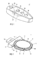
- Figure 2 schematically shows a perspective view of a battery holder 1 according to the invention with a battery 2 arranged thereon.
- the battery 2 is formed as conventional coin cell, for example as lithium-ion cell.
- Figure 2 schematically shows an exploded view of the battery holder 1.
- the battery holder 1 comprises a gripping and gasket element 3 and a holding element 4.
- the holding element 4 is made of a thin metal sheet and is for example formed as embossing part.
- a projection 5 is arranged at one side of the holding element 4.
- a cut-out 6 is formed in the interior of this projection 5.
- the projection 5 and the cut-out 6 are substantially squarely formed.
- Alternative embodiments may make use of different geometries of projection 5 cut-out 6, as for example a circular shape.
- the holding element 4 and thus the battery holder 1 as a whole can be better gripped.
- the holding element 4 is extended to a width in a coupling range 7 attached to the square projection 5, the width substantially corresponding to a diameter of the circular battery 2.
- One respective retaining element 8 is formed on both sides of the square projection 5 in the coupling range 7, which is bended rectangularly or nearly rectangularly to the residual holding element 4 and which projects over the section of the coupling range 7.
- a holding range 9 is attached to the coupling range 7, whereas the surface area of the holding range 9 is formed corresponding to the surface area of the battery 2 to be arranged. As a consequence, this holding range 9 is circularly formed on its end arranged opposite to the square projection 5. This curvature 10 is formed corresponding to the battery 2.
- holding clamps 11 are directly formed on the edges of the holding range 9. These holding clamps 11 are circularly oriented, wherein the circle created by the holding clamps 11 is formed corresponding to the outer diameter of the battery 2.
- the holding clamps 11 are rectangularly or nearly rectangularly formed to the residual holding element 4 in such a matter that a battery 2, arranged in the holding range 9 of the holding element 4, is securely held between the holding clamps 11.
- Guiding ranges 12 are formed on both sides of the holding range 9 on its edge, the guiding ranges 12 projecting the battery 2 inserted in the holding range 9 and corresponding to the not shown guiding grooves being formed in the battery compartment 21 of the key fob 17. Accurate sliding of the battery holder 1 in the guiding grooves of the battery compartment 21 within the key fob 17 is achieved by means of the guiding ranges 12 facilitating an error-free insertion of the battery holder 1 in the key fob 17.
- a gripping and gasket element 3 is arranged in the area of the square projection 5 and/or in the coupling range 7 of the holding element 4. This gripping and gasket element 3 nearly completely encloses the area of the square projection 5 and/or the coupling range 7.
- the gripping and gasket element 3 especially encloses the retaining elements 8 in the coupling range 7, so that a secure and solid connection between holding element 4 and gripping and gasket element 3 is achieved.
- the gripping and gasket element 3 is preferably made of plastics and it is for example adhered, welded or splashed at the holding element 4 in usual manner.
- the gripping and gasket element 3 comprises a handhold range 13 and a sealing range 14 forming a combined one-piece component.
- the sealing range 14 is formed corresponding to the sealing range of the battery compartment 21 within the key fob 17, thus enabling a waterproof ending of the battery compartment 21 within the key fob 17.
- the battery 2 is waterproof arranged during the operation of the key fob 17.
- an additional sealing element can be formed or arranged at the sealing range 14.
- the stability of the holding element 4 being made of a thin sheet metal is significantly improved by the arrangement of the gripping and gasket element 3 at the holding element 4.
- the gripping and gasket element 3 can, at least in certain areas, be provided with a surface coating or a structured surface.
- the battery 2 is securely held between the holding clamps 11 in the holding range 9.
- the electrical contacts 15 and 16 of the battery 2 are thereby freely contactable by means of conventional, not shown contact arrangements.
Landscapes
- Chemical & Material Sciences (AREA)
- Chemical Kinetics & Catalysis (AREA)
- Electrochemistry (AREA)
- General Chemical & Material Sciences (AREA)
- Engineering & Computer Science (AREA)
- Manufacturing & Machinery (AREA)
- Physics & Mathematics (AREA)
- General Physics & Mathematics (AREA)
- Lock And Its Accessories (AREA)
- Battery Mounting, Suspending (AREA)
Abstract
Description
- The invention relates to a battery holder for a key fob according to the preamble of
claim 1. - Key fobs for operating a central locking system of a vehicle by remote control are known as prior art. Conventional coin cells being an energy storage device are inserted in these key fobs and are covered by separate cover.
- It is an object of the present invention to give an improved battery holder for a key fob, the battery holder being especially space and cost saving, contact secure and easy to operate, especially without to open the tight aria of the Button and Rear Covers.
- This object according to the invention is achieved by the features given in
claim 1. - Preferred embodiments of the invention are given in the dependent claims.
- According to the invention concerning the battery holder for a key fob, a holding element is enclosed by a gripping and gasket element, at least in sections or area by area, wherein a holding range is formed on the holding element and guiding ranges are formed on both sides of the holding range on its edge, the guiding ranges being formed in a manner that they correspond to guiding grooves within the key fob. Thus, a compact battery holder is created using the limited space within the key fob in a better way. A base area of the holding range is formed corresponding to the base area of a battery to be arranged. Thus, the battery holder for the battery to be arranged is formed in an optimised way.
- In a preferred embodiment, several, preferably four, circularly oriented holding clamps are directly formed on edges of the holding range, wherein the circle being created by the holding clamps is formed corresponding to the outer diameter of the battery.
- Preferably, the holding clamps are rectangularly or nearly rectangularly oriented to the residual holding element in such a manner that a battery, being arranged in the holding range of the holding element, is securely held between the holding clamps.
- The holding element is preferably made of a robust thin material, preferably a thin sheet metal. That is why the holding element is light, robust and easily electrically connectable.
- The gripping and gasket element is preferably made of sealed not electrical conductive material, by what it can be easily produced, for example using an injection moulding process.
- The gripping and gasket element especially preferably comprises a handhold range and a sealing range forming a combined one-piece component. Such an integrated component facilitates production of the battery holder and reduces its production time.
- The sealing range of the gripping and gasket element is formed corresponding to a sealing range within the key fob. A waterproof cavity is formed in the key fob as battery compartment corresponding to the battery holder enabling the holding of the battery holder. A sealing range is arranged on the input range of the battery compartment. The sealing ranges of the gripping and gasket elements and the battery compartment, being formed and arranged corresponding to one another, enable a waterproof or at least water-protected arrangement of the battery within the battery compartment of the key fob.
- In a particular advantageous embodiment, an additional sealing element can be formed or arranged at the sealing range of the gripping and gasket element, resulting in the battery compartment and its sealing can being more resistant to higher water pressure.
- In another advantageous embodiment, the gripping and gasket element is at least in certain areas provided with a surface coating or a structured surface. Thus, a better grip of the handhold range or an adaptation of the surface feel of the handhold range to the particular customer wishes and needs is enabled.
- In a preferred embodiment, electrical contacts and the battery being arranged in the battery holder are freely contactable. Thus, electric energy can be easily obtained from the battery arranged in the battery holder.
- The invention is described in more detail by the enclosed schematic figures, wherein:
- Figure 1
- schematically shows a perspective view of a key fob with a battery holder according to the invention,
- Figure 2
- schematically shows a perspective view of a battery holder according to the invention with a battery arranged thereon and
- Figure 3
- schematically shows an exploded view of the battery holder.
- Corresponding parts are marked with the same reference symbols in all figures.
- In
figure 1 , a perspective view of akey fob 17 with abattery holder 1 according to the invention is schematically shown. Such akey fob 17 is formed as usual remote control for a central locking system of a vehicle. For that purpose thekey fob 17 comprises ahousing 19,several control elements 18 and acoupling element 20, by which thekey fob 17 can for example be arranged on a bunch of keys. - A
battery compartment 21 is arranged in the interior of thekey fob 17. Thisbattery compartment 21 is formed corresponding to thebattery holder 1 and it is formed as waterproof cavity. A not shown sealing range is formed within the inlet or entrance area of the cavity. When operating thekey fob 17, thebattery holder 1, with thebattery 2 arranged thereon, is arranged in thebattery compartment 21 supplying thekey fob 17 with electrical energy. -
Figure 2 schematically shows a perspective view of abattery holder 1 according to the invention with abattery 2 arranged thereon. - The
battery 2 is formed as conventional coin cell, for example as lithium-ion cell. -
Figure 2 schematically shows an exploded view of thebattery holder 1. - The
battery holder 1 comprises a gripping andgasket element 3 and a holding element 4. - The holding element 4 is made of a thin metal sheet and is for example formed as embossing part.
- A projection 5 is arranged at one side of the holding element 4. A cut-out 6 is formed in the interior of this projection 5.
- According to the embodiment of the invention described herein, the projection 5 and the cut-out 6 are substantially squarely formed. Alternative embodiments may make use of different geometries of projection 5 cut-out 6, as for example a circular shape.
- Due to the cut-out 6, the holding element 4 and thus the
battery holder 1 as a whole can be better gripped. - The holding element 4 is extended to a width in a coupling range 7 attached to the square projection 5, the width substantially corresponding to a diameter of the
circular battery 2. - One respective
retaining element 8 is formed on both sides of the square projection 5 in the coupling range 7, which is bended rectangularly or nearly rectangularly to the residual holding element 4 and which projects over the section of the coupling range 7. - A
holding range 9 is attached to the coupling range 7, whereas the surface area of theholding range 9 is formed corresponding to the surface area of thebattery 2 to be arranged. As a consequence, thisholding range 9 is circularly formed on its end arranged opposite to the square projection 5. Thiscurvature 10 is formed corresponding to thebattery 2. - Four
holding clamps 11 are directly formed on the edges of theholding range 9. Theseholding clamps 11 are circularly oriented, wherein the circle created by theholding clamps 11 is formed corresponding to the outer diameter of thebattery 2. Theholding clamps 11 are rectangularly or nearly rectangularly formed to the residual holding element 4 in such a matter that abattery 2, arranged in theholding range 9 of the holding element 4, is securely held between theholding clamps 11. -
Guiding ranges 12 are formed on both sides of theholding range 9 on its edge, the guidingranges 12 projecting thebattery 2 inserted in theholding range 9 and corresponding to the not shown guiding grooves being formed in thebattery compartment 21 of thekey fob 17. Accurate sliding of thebattery holder 1 in the guiding grooves of thebattery compartment 21 within thekey fob 17 is achieved by means of the guidingranges 12 facilitating an error-free insertion of thebattery holder 1 in thekey fob 17. - A gripping and
gasket element 3 is arranged in the area of the square projection 5 and/or in the coupling range 7 of the holding element 4. This gripping andgasket element 3 nearly completely encloses the area of the square projection 5 and/or the coupling range 7. - The gripping and
gasket element 3 especially encloses theretaining elements 8 in the coupling range 7, so that a secure and solid connection between holding element 4 and gripping andgasket element 3 is achieved. - The gripping and
gasket element 3 is preferably made of plastics and it is for example adhered, welded or splashed at the holding element 4 in usual manner. - The gripping and
gasket element 3 comprises ahandhold range 13 and asealing range 14 forming a combined one-piece component. - The
sealing range 14 is formed corresponding to the sealing range of thebattery compartment 21 within thekey fob 17, thus enabling a waterproof ending of thebattery compartment 21 within thekey fob 17. Thus, thebattery 2 is waterproof arranged during the operation of thekey fob 17. - In a not shown embodiment, an additional sealing element can be formed or arranged at the
sealing range 14. - The stability of the holding element 4 being made of a thin sheet metal is significantly improved by the arrangement of the gripping and
gasket element 3 at the holding element 4. Advantageously, especially the stability and the grip of the projection 5 and thehandhold range 13 are increased. - For achieving another increase of grip or for adapting the surface feel of the
handhold range 13 to the particular customer wishes and needs, the gripping andgasket element 3 can, at least in certain areas, be provided with a surface coating or a structured surface. - During operation of the
battery holder 1, thebattery 2 is securely held between the holding clamps 11 in theholding range 9. Theelectrical contacts battery 2 are thereby freely contactable by means of conventional, not shown contact arrangements. -
- 1
- battery holder
- 2
- battery
- 3
- gripping and gasket element
- 4
- holding element
- 5
- projection
- 6
- cut-out
- 7
- coupling range
- 8
- retaining element
- 9
- holding range
- 10
- curvature
- 11
- holding clamp
- 12
- guiding range
- 13
- handhold range
- 14
- sealing range
- 15
- electrical contact
- 16
- electrical contact
- 17
- key fob
- 18
- control element
- 19
- housing
- 20
- coupling element
- 21
- battery compartment
Claims (11)
- A battery holder (1) for a key fob (17),
characterised in that
a holding element (4) is enclosed by a gripping and gasket element (3) at least in sections or area by area, wherein a holding range (9) is formed at the holding element (4) and guiding ranges (12) are formed at both sides of the holding range (9) on its edge, wherein the guiding ranges (12) are formed corresponding to guiding grooves within the key fob (17). - The battery holder (1) according to claim 1,
characterised in that
a base area of the holding range (9) is formed corresponding to a base area of a battery (2) to be arranged. - The battery holder (1) according to claim 1 or 2,
characterised in that several, preferably four, circularly oriented holding clamps (11) are directly formed on the edges of the holding range (9), whereas the circle being created by the holding clamps (11) is formed corresponding to the outer diameter of the battery (2). - The battery holder (1) according to claim 3,
characterised in that the holding clamps (11) are rectangularly or nearly rectangularly oriented to the residual holding element (4) in such a manner that a battery (2), being arranged in the holding range (9) of the holding element (4), is securely held between the holding clamps (11). - The battery holder (1) according to claim 1,
characterised in that
the holding element (4) is made of a sheet metal. - The battery holder (1) according to claim 1,
characterised in that
the gripping and gasket element (3) is made of plastics. - The battery holder (1) according to claim 1 or 6,
characterised in that
the gripping and gasket element (3) comprises a handhold range (13) and a sealing range (14) forming a combined one-piece component. - The battery holder (1) according to claim 1, 6 or 7,
characterised in that
the sealing range (14) of the gripping and gasket element (3) is formed corresponding to a sealing range within the key fob (17). - The battery holder (1) according to claim 1, 6, 7 or 8, characterised in that
an additional sealing element is formed or arranged at the sealing range (14) of the gripping and gasket element (3). - The battery holder (1) according to one of the preceding claims, characterised in that
the gripping and gasket element (3) is, at least in certain areas, provided with a surface coating or a structured surface. - The battery holder (1) according to one of the preceding claims, characterised in that
the electrical contacts (15) and (16) of the battery (2) arranged in the battery holder (1) are freely contactable.
Applications Claiming Priority (1)
| Application Number | Priority Date | Filing Date | Title |
|---|---|---|---|
| DE102010034404 | 2010-08-14 |
Publications (1)
| Publication Number | Publication Date |
|---|---|
| EP2418626A1 true EP2418626A1 (en) | 2012-02-15 |
Family
ID=44834973
Family Applications (1)
| Application Number | Title | Priority Date | Filing Date |
|---|---|---|---|
| EP10191412A Withdrawn EP2418626A1 (en) | 2010-08-14 | 2010-11-16 | Battery holder for a key fob |
Country Status (1)
| Country | Link |
|---|---|
| EP (1) | EP2418626A1 (en) |
Cited By (1)
| Publication number | Priority date | Publication date | Assignee | Title |
|---|---|---|---|---|
| EP2642455A3 (en) * | 2012-03-22 | 2017-05-10 | Huf Hülsbeck & Fürst GmbH & Co. KG | Electronic key with a battery holder |
Citations (3)
| Publication number | Priority date | Publication date | Assignee | Title |
|---|---|---|---|---|
| US5188912A (en) * | 1990-04-18 | 1993-02-23 | Sony Corporation | Button battery holder |
| EP0825520A1 (en) * | 1996-02-26 | 1998-02-25 | Citizen Watch Co. Ltd. | Portable information equipment |
| DE10240811A1 (en) * | 2002-08-30 | 2004-03-11 | Leopold Kostal Gmbh & Co Kg | Electronic key e.g. for automobile is powered by a small battery cell and the unit also has a mechanical key |
-
2010
- 2010-11-16 EP EP10191412A patent/EP2418626A1/en not_active Withdrawn
Patent Citations (3)
| Publication number | Priority date | Publication date | Assignee | Title |
|---|---|---|---|---|
| US5188912A (en) * | 1990-04-18 | 1993-02-23 | Sony Corporation | Button battery holder |
| EP0825520A1 (en) * | 1996-02-26 | 1998-02-25 | Citizen Watch Co. Ltd. | Portable information equipment |
| DE10240811A1 (en) * | 2002-08-30 | 2004-03-11 | Leopold Kostal Gmbh & Co Kg | Electronic key e.g. for automobile is powered by a small battery cell and the unit also has a mechanical key |
Cited By (1)
| Publication number | Priority date | Publication date | Assignee | Title |
|---|---|---|---|---|
| EP2642455A3 (en) * | 2012-03-22 | 2017-05-10 | Huf Hülsbeck & Fürst GmbH & Co. KG | Electronic key with a battery holder |
Similar Documents
| Publication | Publication Date | Title |
|---|---|---|
| EP2352208B1 (en) | Charging connector | |
| US7883360B2 (en) | Battery pack | |
| CN103094499B (en) | The cover piece of electrochemical appliance contacts the method connected with to electrochemical cell unit | |
| US10513311B1 (en) | Integrated bicycle control device | |
| US8684106B2 (en) | Battery pack and motor-driven tool using the same | |
| US8703312B2 (en) | Battery module | |
| CA2621051A1 (en) | Razors | |
| US20120202365A1 (en) | Charging connector and method of mounting it | |
| CN103907221A (en) | Battery wiring module | |
| CN217607501U (en) | Charger adapted to charge either of first battery pack and second battery pack, and kit | |
| CN105981201B (en) | Wiring module and power storage module | |
| CN103733378B (en) | It is adapted to assist in the device of the fracture of the vent of electrochemical cell | |
| JP2018063944A (en) | Energy storage apparatus | |
| JP5924041B2 (en) | Electric tool set | |
| EP2418626A1 (en) | Battery holder for a key fob | |
| JP2002050331A (en) | Power supply device for portable devices suitable for use with different types of power supply | |
| JP2007144813A (en) | Mold for producing power tool | |
| US9312622B2 (en) | Connecting element for a storage battery | |
| CN110854318B (en) | Battery | |
| JP5519476B2 (en) | Actuator | |
| EP1952717A3 (en) | Key-holder with an interchangeable cover and retractable key, in particular for a vehicle lock | |
| KR101350951B1 (en) | A fob key for vehicles | |
| USD1037941S1 (en) | Electric motorbike battery compartment | |
| EP2500961B1 (en) | Housing arrangement for an electrical energy storage | |
| CN103363494A (en) | Light-emitting diode (LED) flashlight and battery case assembly thereof |
Legal Events
| Date | Code | Title | Description |
|---|---|---|---|
| AK | Designated contracting states |
Kind code of ref document: A1 Designated state(s): AL AT BE BG CH CY CZ DE DK EE ES FI FR GB GR HR HU IE IS IT LI LT LU LV MC MK MT NL NO PL PT RO RS SE SI SK SM TR |
|
| AX | Request for extension of the european patent |
Extension state: BA ME |
|
| PUAI | Public reference made under article 153(3) epc to a published international application that has entered the european phase |
Free format text: ORIGINAL CODE: 0009012 |
|
| 17P | Request for examination filed |
Effective date: 20120724 |
|
| 17Q | First examination report despatched |
Effective date: 20161122 |
|
| RAP1 | Party data changed (applicant data changed or rights of an application transferred) |
Owner name: JOHNSON CONTROLS TECHNOLOGY COMPANY |
|
| STAA | Information on the status of an ep patent application or granted ep patent |
Free format text: STATUS: THE APPLICATION IS DEEMED TO BE WITHDRAWN |
|
| 18D | Application deemed to be withdrawn |
Effective date: 20170404 |