EP2418365A1 - Combustion chamber for diesel engines with inclined engine valves - Google Patents
Combustion chamber for diesel engines with inclined engine valves Download PDFInfo
- Publication number
- EP2418365A1 EP2418365A1 EP10425275A EP10425275A EP2418365A1 EP 2418365 A1 EP2418365 A1 EP 2418365A1 EP 10425275 A EP10425275 A EP 10425275A EP 10425275 A EP10425275 A EP 10425275A EP 2418365 A1 EP2418365 A1 EP 2418365A1
- Authority
- EP
- European Patent Office
- Prior art keywords
- cylinder
- combustion chamber
- intake
- axis
- cylinder head
- Prior art date
- Legal status (The legal status is an assumption and is not a legal conclusion. Google has not performed a legal analysis and makes no representation as to the accuracy of the status listed.)
- Granted
Links
Images




Classifications
-
- F—MECHANICAL ENGINEERING; LIGHTING; HEATING; WEAPONS; BLASTING
- F02—COMBUSTION ENGINES; HOT-GAS OR COMBUSTION-PRODUCT ENGINE PLANTS
- F02B—INTERNAL-COMBUSTION PISTON ENGINES; COMBUSTION ENGINES IN GENERAL
- F02B23/00—Other engines characterised by special shape or construction of combustion chambers to improve operation
- F02B23/02—Other engines characterised by special shape or construction of combustion chambers to improve operation with compression ignition
- F02B23/04—Other engines characterised by special shape or construction of combustion chambers to improve operation with compression ignition the combustion space being subdivided into two or more chambers
-
- F—MECHANICAL ENGINEERING; LIGHTING; HEATING; WEAPONS; BLASTING
- F02—COMBUSTION ENGINES; HOT-GAS OR COMBUSTION-PRODUCT ENGINE PLANTS
- F02B—INTERNAL-COMBUSTION PISTON ENGINES; COMBUSTION ENGINES IN GENERAL
- F02B23/00—Other engines characterised by special shape or construction of combustion chambers to improve operation
- F02B23/02—Other engines characterised by special shape or construction of combustion chambers to improve operation with compression ignition
- F02B23/06—Other engines characterised by special shape or construction of combustion chambers to improve operation with compression ignition the combustion space being arranged in working piston
- F02B23/0618—Other engines characterised by special shape or construction of combustion chambers to improve operation with compression ignition the combustion space being arranged in working piston having in-cylinder means to influence the charge motion
- F02B23/0621—Squish flow
-
- F—MECHANICAL ENGINEERING; LIGHTING; HEATING; WEAPONS; BLASTING
- F02—COMBUSTION ENGINES; HOT-GAS OR COMBUSTION-PRODUCT ENGINE PLANTS
- F02B—INTERNAL-COMBUSTION PISTON ENGINES; COMBUSTION ENGINES IN GENERAL
- F02B23/00—Other engines characterised by special shape or construction of combustion chambers to improve operation
- F02B23/02—Other engines characterised by special shape or construction of combustion chambers to improve operation with compression ignition
- F02B23/06—Other engines characterised by special shape or construction of combustion chambers to improve operation with compression ignition the combustion space being arranged in working piston
- F02B23/0618—Other engines characterised by special shape or construction of combustion chambers to improve operation with compression ignition the combustion space being arranged in working piston having in-cylinder means to influence the charge motion
- F02B23/063—Other engines characterised by special shape or construction of combustion chambers to improve operation with compression ignition the combustion space being arranged in working piston having in-cylinder means to influence the charge motion the combustion space in the piston interacting fluid dynamically with the cylinder head, the injector body or the cylinder wall
-
- F—MECHANICAL ENGINEERING; LIGHTING; HEATING; WEAPONS; BLASTING
- F01—MACHINES OR ENGINES IN GENERAL; ENGINE PLANTS IN GENERAL; STEAM ENGINES
- F01L—CYCLICALLY OPERATING VALVES FOR MACHINES OR ENGINES
- F01L3/00—Lift-valve, i.e. cut-off apparatus with closure members having at least a component of their opening and closing motion perpendicular to the closing faces; Parts or accessories thereof
- F01L2003/25—Valve configurations in relation to engine
- F01L2003/255—Valve configurations in relation to engine configured other than parallel or symmetrical relative to piston axis
-
- F—MECHANICAL ENGINEERING; LIGHTING; HEATING; WEAPONS; BLASTING
- F01—MACHINES OR ENGINES IN GENERAL; ENGINE PLANTS IN GENERAL; STEAM ENGINES
- F01L—CYCLICALLY OPERATING VALVES FOR MACHINES OR ENGINES
- F01L3/00—Lift-valve, i.e. cut-off apparatus with closure members having at least a component of their opening and closing motion perpendicular to the closing faces; Parts or accessories thereof
- F01L2003/25—Valve configurations in relation to engine
- F01L2003/256—Valve configurations in relation to engine configured other than perpendicular to camshaft axis
-
- F—MECHANICAL ENGINEERING; LIGHTING; HEATING; WEAPONS; BLASTING
- F01—MACHINES OR ENGINES IN GENERAL; ENGINE PLANTS IN GENERAL; STEAM ENGINES
- F01L—CYCLICALLY OPERATING VALVES FOR MACHINES OR ENGINES
- F01L3/00—Lift-valve, i.e. cut-off apparatus with closure members having at least a component of their opening and closing motion perpendicular to the closing faces; Parts or accessories thereof
-
- F—MECHANICAL ENGINEERING; LIGHTING; HEATING; WEAPONS; BLASTING
- F02—COMBUSTION ENGINES; HOT-GAS OR COMBUSTION-PRODUCT ENGINE PLANTS
- F02B—INTERNAL-COMBUSTION PISTON ENGINES; COMBUSTION ENGINES IN GENERAL
- F02B2275/00—Other engines, components or details, not provided for in other groups of this subclass
- F02B2275/14—Direct injection into combustion chamber
-
- F—MECHANICAL ENGINEERING; LIGHTING; HEATING; WEAPONS; BLASTING
- F02—COMBUSTION ENGINES; HOT-GAS OR COMBUSTION-PRODUCT ENGINE PLANTS
- F02B—INTERNAL-COMBUSTION PISTON ENGINES; COMBUSTION ENGINES IN GENERAL
- F02B2275/00—Other engines, components or details, not provided for in other groups of this subclass
- F02B2275/40—Squish effect
-
- F—MECHANICAL ENGINEERING; LIGHTING; HEATING; WEAPONS; BLASTING
- F02—COMBUSTION ENGINES; HOT-GAS OR COMBUSTION-PRODUCT ENGINE PLANTS
- F02B—INTERNAL-COMBUSTION PISTON ENGINES; COMBUSTION ENGINES IN GENERAL
- F02B23/00—Other engines characterised by special shape or construction of combustion chambers to improve operation
- F02B23/02—Other engines characterised by special shape or construction of combustion chambers to improve operation with compression ignition
- F02B23/06—Other engines characterised by special shape or construction of combustion chambers to improve operation with compression ignition the combustion space being arranged in working piston
- F02B23/0672—Omega-piston bowl, i.e. the combustion space having a central projection pointing towards the cylinder head and the surrounding wall being inclined towards the cylinder center axis
-
- F—MECHANICAL ENGINEERING; LIGHTING; HEATING; WEAPONS; BLASTING
- F02—COMBUSTION ENGINES; HOT-GAS OR COMBUSTION-PRODUCT ENGINE PLANTS
- F02B—INTERNAL-COMBUSTION PISTON ENGINES; COMBUSTION ENGINES IN GENERAL
- F02B3/00—Engines characterised by air compression and subsequent fuel addition
- F02B3/06—Engines characterised by air compression and subsequent fuel addition with compression ignition
-
- F—MECHANICAL ENGINEERING; LIGHTING; HEATING; WEAPONS; BLASTING
- F02—COMBUSTION ENGINES; HOT-GAS OR COMBUSTION-PRODUCT ENGINE PLANTS
- F02F—CYLINDERS, PISTONS OR CASINGS, FOR COMBUSTION ENGINES; ARRANGEMENTS OF SEALINGS IN COMBUSTION ENGINES
- F02F1/00—Cylinders; Cylinder heads
- F02F1/24—Cylinder heads
- F02F1/42—Shape or arrangement of intake or exhaust channels in cylinder heads
- F02F1/4214—Shape or arrangement of intake or exhaust channels in cylinder heads specially adapted for four or more valves per cylinder
-
- F—MECHANICAL ENGINEERING; LIGHTING; HEATING; WEAPONS; BLASTING
- F02—COMBUSTION ENGINES; HOT-GAS OR COMBUSTION-PRODUCT ENGINE PLANTS
- F02F—CYLINDERS, PISTONS OR CASINGS, FOR COMBUSTION ENGINES; ARRANGEMENTS OF SEALINGS IN COMBUSTION ENGINES
- F02F1/00—Cylinders; Cylinder heads
- F02F1/24—Cylinder heads
- F02F1/42—Shape or arrangement of intake or exhaust channels in cylinder heads
- F02F1/4235—Shape or arrangement of intake or exhaust channels in cylinder heads of intake channels
-
- Y—GENERAL TAGGING OF NEW TECHNOLOGICAL DEVELOPMENTS; GENERAL TAGGING OF CROSS-SECTIONAL TECHNOLOGIES SPANNING OVER SEVERAL SECTIONS OF THE IPC; TECHNICAL SUBJECTS COVERED BY FORMER USPC CROSS-REFERENCE ART COLLECTIONS [XRACs] AND DIGESTS
- Y02—TECHNOLOGIES OR APPLICATIONS FOR MITIGATION OR ADAPTATION AGAINST CLIMATE CHANGE
- Y02T—CLIMATE CHANGE MITIGATION TECHNOLOGIES RELATED TO TRANSPORTATION
- Y02T10/00—Road transport of goods or passengers
- Y02T10/10—Internal combustion engine [ICE] based vehicles
- Y02T10/12—Improving ICE efficiencies
Definitions
- the present invention refers to diesel engines of the type comprising at least one cylinder defined in a engine block, a cylinder head having a bottom surface delimiting a combustion chamber associated to said cylinder, at least two intake valves and two exhaust valves associated to said cylinder, which control respective intake and exhaust conduits formed in said cylinder head and ending up on said bottom surface of the head delimiting the combustion chamber, wherein said surface is a mainly flat surface and orthogonal to the axis of the cylinder.
- intake and exhaust valves have their axis inclined with respect to the axis of the cylinder by an angle not greater than 3-4°.
- the surface of the head delimiting the combustion chamber is a flat surface (the so-called “flame plate”) substantially coplanar with the bottom face of the cylinder head.
- the combustion chamber is almost entirely defined by a cavity (the so-called “bowl”) obtained in the head of the piston.
- the air motions - required to guarantee proper mixing of the diesel fuel injected into the combustion chamber and an ensuing ideal combustion - are characterized by a vortex with an axis parallel to the cylinder axis, referred to as "swirl".
- swirl motion is indicated by the arrow SW in figure 1 of the attached drawings, which shows - in a plane orthogonal to the cylinder axis - the combustion chamber associated to the cylinder, indicated with reference number 1, into which the two intake conduits A1, A2, and the two exhaust conduits S1, S2 end up.
- the first intake conduit A1 has a scroll-shaped end, suitable to impart a helical movement (indicated by the arrow C in figure 1 ) to the airflow while the second intake conduit A2 directs the airflow which reaches into the combustion chamber according to a direction tangential with respect to the axis of the combustion chamber.
- the abovementioned shape of the intake conduits is selected to generate the desired swirl motion SW.
- the reduction of the radius of the air vortex in the "bowl” causes, according to the principle of preservation of the quantity of motion, an increase of speed.
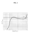
- FIG. 2 The variation of the swirl ratio in a conventional diesel engine during the intake and compression stages is illustrated in figure 2 in the attached drawings.
- the diagram in such figure shows that the achievement of the ideal value for the combustion, at 360° of crank angle, is mostly caused by the swirl motion generated by the shape of the intake conduits (see the part of the diagram comprised between 120° and 320°) and for a final part - corresponding to the final compression stage - by the "spin-up" phenomenon.
- spin-up is instead relatively low in the case of conventional petrol engines, in which the intake and exhaust valves usually have their axis considerably inclined with respect to the to the axis of the cylinder (according to an angle usually greater than 8°), hence the surface of the cylinder head delimiting the combustion chamber is not a coplanar flat surface at the bottom face of the head, but it is defined by a cavity which forms a considerable part of the volume of the combustion chamber when the piston is at the top dead centre.
- FIG. 3 of the attached drawings shows, by way of reference, the abovementioned tumble motions in a cylinder of a petrol engine during the intake step (left part of the figure) and during the compression step (right part of the figure).
- the views of figure 3 are sections according to a dashed line III-III, also indicated in such figure, through the axes of an intake valve and of an exhaust valve.
- such views just illustrate the combustion chamber, i.e. the part comprised between the surface of the chamber defined by the cylinder head and the top surface of the piston (which is illustrated at a higher position in the right part of the figure).
- the aim of the present invention is that of providing a new shape of the combustion chamber for diesel engines capable of allowing standardising - at least to a given extent - the architecture of such engines with that of petrol engines, so as to allow considerable simplification and reduction of costs when manufacturing and assembling such engines.
- the two intake conduits A1, A2 have a conventional shape, one having a scroll-shaped end part, the other having a tangential end part with respect to the cylinder axis.
- the exhaust conduits S1, S2 also have a conventional shape.
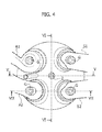
- Figure 4 shows - also schematically - the seat 2 at the centre of the combustion chamber, for fuel injector (visible in figure 8 and indicated with reference number 3 therein). The seat 4 for the glow plug is also shown.
- tubular guide portions G of the stems of the intake and exhaust valves, VA1, VA2 and VS1, VS2, which have the conventional mushroom shape, with the bottom heads which are shown in figure 8 and which, in the closed condition of the valves, lay against respective valve seats defined by the edges 5 of the ends of the conduits A1, A2, S1, S2 which end up in the combustion chamber, are shown in figure 4 and figure 7 .
- reference P is used to indicate the piston slidable in the engine cylinder (which is also illustrated in the top dead centre in such figures), while references B and H respectively indicate the body of the engine block in which the cylinder and the cylinder head, whose bottom surface is indicated with H1 (also see figure 8 ), is obtained.
- the cavity or bowl formed in the head of the piston is indicated with reference P1.
- a main characteristic of the engine according to the invention lies in the fact that both the intake valves and the exhaust valves have their axis VX ( figure 7 ) which is inclined with respect to the axis CX of the cylinder by an angle ⁇ greater than 8°.
- Such inclination of the valves forces the creation of large recesses in the cylinder head having the drawback of breaking the swirl vortex during the compression stage, hence jeopardising the "spin-up" effect.
- An indicatively frusto-conical-shaped combustion chamber was created in the cylinder head in order to overcome this phenomenon.
- the combustion chamber is defined, when the piston is at the top dead centre (see figures 5, 6 ) not only by the bowl P1 (which might be much less deep with respect to the conventional shape), but also by a substantially frusto-conical cavity, indicated in its entirety in figures 5, 6 with reference CO and obtained in the bottom surface H1 of the cylinder head.
- the cavity CO has a circular main central portion, indicated with CO1 in figure 8 , which is flat, parallel to the flat bottom surface H1 of the head H and spaced therefrom by a height h (see figure 5, 6 ).
- the flat circular central portion CO1 of the cavity CO is joined to the bottom surface H1 of the head by an annular portion CO2, substantially conical, which more precisely has a slightly rounded or arched profile, dome-like.
- the combustion chamber thus defined allows the formation of swirl motions during the intake stage, but the "spin-up" effect, crucial for the achievement of the ideal end swirl value, is considerably low.
- the intake and exhaust conduits and the surfaces that join the ends thereof to the bottom surface of the head are made in a manner to form an even more intense swirl motion, enough to achieve the ideal value, which - in the conventional engines - is attained after compression, right from the intake stage.
- FIG 7 Such characteristic is clearly illustrated in figure 7 (in which the cavities and the conduits of the head have been shown as solid parts), with reference to the intake conduit A2, whose end edge 5, defining the seat for the respective valve VA2, is joined to the bottom surface H1 of the head and to the surface of the cavity CO of the combustion chamber (see figure 8 ) through a concentric tapered annular surface 6 with the valve axis VX and forming - with such axis - an angle ⁇ whose value may vary between 0° (cylindrical operation) and 60°.
- the angle ⁇ may also be different as regards with the main intake conduit A1 and the secondary intake conduit A2, and same case applies for the exhaust conduits with respect to each other and with respect to the intake conduits. The choice of such angles allows modulating the final value of the swirl at will.
- line T indicates the diagram previously illustrated in figure 2 , which shows the variation of the swirl ratio in a conventional diesel engine
- line N shows the variation of the swirl ratio in the engine according to the invention.
- the engine according to the invention is capable of achieving at the end of the compression stage a swirl ratio value substantially similar, in spite of the fact that the "spin-up" effect is almost absent, due to the increase of the swirl effect during the intake stage. As indicated, such increase is due to the specific shape of the combustion chamber and the joining surfaces 6 described above.
- the arrangement of valves inclined according to angles similar to those used for petrol engines allows simplifying and standardising the manufacture of the diesel engine with respect to that of the petrol engine.
- the diesel engine according to the invention due to the previously described shape, has a considerably smaller overall height with respect to a conventional engine.
- the cylinder head and the valves actuation system after selecting the valve lift value, are more compact in height, due to the inclination of the valves.
- the fact that part of the combustion chamber is obtained in the cylinder head allows reducing the height of the bowl in the piston.
- the piston acquires a lower compression height (pin axis - piston top surface distance) and a lower weight.
Landscapes
- Engineering & Computer Science (AREA)
- Chemical & Material Sciences (AREA)
- Combustion & Propulsion (AREA)
- Mechanical Engineering (AREA)
- General Engineering & Computer Science (AREA)
- Physics & Mathematics (AREA)
- Fluid Mechanics (AREA)
- Cylinder Crankcases Of Internal Combustion Engines (AREA)
- Combustion Methods Of Internal-Combustion Engines (AREA)
Abstract
Description
- The present invention refers to diesel engines of the type comprising at least one cylinder defined in a engine block, a cylinder head having a bottom surface delimiting a combustion chamber associated to said cylinder, at least two intake valves and two exhaust valves associated to said cylinder, which control respective intake and exhaust conduits formed in said cylinder head and ending up on said bottom surface of the head delimiting the combustion chamber, wherein said surface is a mainly flat surface and orthogonal to the axis of the cylinder.
- In diesel engines of the conventional type, intake and exhaust valves have their axis inclined with respect to the axis of the cylinder by an angle not greater than 3-4°. The surface of the head delimiting the combustion chamber is a flat surface (the so-called "flame plate") substantially coplanar with the bottom face of the cylinder head. When the piston is at the top dead centre, the combustion chamber is almost entirely defined by a cavity (the so-called "bowl") obtained in the head of the piston.
- During the operation of the engine, the air motions - required to guarantee proper mixing of the diesel fuel injected into the combustion chamber and an ensuing ideal combustion - are characterized by a vortex with an axis parallel to the cylinder axis, referred to as "swirl". Such swirl motion is indicated by the arrow SW in
figure 1 of the attached drawings, which shows - in a plane orthogonal to the cylinder axis - the combustion chamber associated to the cylinder, indicated withreference number 1, into which the two intake conduits A1, A2, and the two exhaust conduits S1, S2 end up. According to an art known art per se, the first intake conduit A1 has a scroll-shaped end, suitable to impart a helical movement (indicated by the arrow C infigure 1 ) to the airflow while the second intake conduit A2 directs the airflow which reaches into the combustion chamber according to a direction tangential with respect to the axis of the combustion chamber. The abovementioned shape of the intake conduits is selected to generate the desired swirl motion SW. Furthermore, in the operation of the engine, during the stage of compression in the cylinder, in which the intake valves are closed, the vorticity of the air motion is determined by the so-called "spin-up" phenomenon due to the fact that the air vortex is pushed into the abovementioned "bowl" during the ascent of the piston. The reduction of the radius of the air vortex in the "bowl" causes, according to the principle of preservation of the quantity of motion, an increase of speed. The swirl is quantitatively represented by the "swirl ratio" (Rs = Ωeq z / Ωmot where Ωeq z is the equivalent rotational speed of the fluid vortex around cylinder axis, intended as the ratio between the angular momentum and the inertia momentum of the mass distribution, while Ωmot is the rotational speed of the driving shaft). - The variation of the swirl ratio in a conventional diesel engine during the intake and compression stages is illustrated in
figure 2 in the attached drawings. The diagram in such figure shows that the achievement of the ideal value for the combustion, at 360° of crank angle, is mostly caused by the swirl motion generated by the shape of the intake conduits (see the part of the diagram comprised between 120° and 320°) and for a final part - corresponding to the final compression stage - by the "spin-up" phenomenon. - The "spin-up" is instead relatively low in the case of conventional petrol engines, in which the intake and exhaust valves usually have their axis considerably inclined with respect to the to the axis of the cylinder (according to an angle usually greater than 8°), hence the surface of the cylinder head delimiting the combustion chamber is not a coplanar flat surface at the bottom face of the head, but it is defined by a cavity which forms a considerable part of the volume of the combustion chamber when the piston is at the top dead centre.
- In the case of petrol engines, the main air motions that contribute to the ideal turbulence for combustion are made up of a horizontal axis vortex referred to as tumble.
Figure 3 of the attached drawings shows, by way of reference, the abovementioned tumble motions in a cylinder of a petrol engine during the intake step (left part of the figure) and during the compression step (right part of the figure). The views offigure 3 are sections according to a dashed line III-III, also indicated in such figure, through the axes of an intake valve and of an exhaust valve. Furthermore, such views just illustrate the combustion chamber, i.e. the part comprised between the surface of the chamber defined by the cylinder head and the top surface of the piston (which is illustrated at a higher position in the right part of the figure). - The different inclination of the engine valves in diesel engines and in petrol engines gives rise to complications when constructing engines, hence complicating the joining of the components and the construction lines as well as assembling such engines.
- The aim of the present invention is that of providing a new shape of the combustion chamber for diesel engines capable of allowing standardising - at least to a given extent - the architecture of such engines with that of petrol engines, so as to allow considerable simplification and reduction of costs when manufacturing and assembling such engines.
- According to the invention, such object is attained due to the characteristics indicated in the attached
claim 1. Further preferred and advantageous characteristics of the invention are indicated in the attached dependent claims. - Now, the invention shall be described with reference to the attached drawings, purely provided by way of non-limiting example, wherein:
-
figure 1 , already described above, illustrates the combustion chamber of a conventional diesel engine, -
figure 2 , already described above, illustrates the variation of the swirl ratio in a conventional diesel engine, -
figure 3 , already described above, illustrates the tumble motions in a conventional petrol engine, -
figure 4 is a view in a plane orthogonal to the axis of the cylinder of the combustion chamber according to the invention, -
figures 5, 6 are sectional views according to lines V-V and VI-VI offigure 4 , -
figure 7 is a further view according to line VII-VII offigure 4 , -
figure 8 is a perspective view of the bottom surface of the cylinder head defining the combustion chamber according to the invention, and -
figure 9 is a diagram showing the variation of the swirl ratio that occurs in the case of the combustion chamber according to dimensions compared to that of a conventional diesel engine. - Referring to
figure 4 of the attached drawings, in such figure the parts common with those offigure 1 are indicated using the same reference number. - Even in the case of the combustion chamber according to the invention two intake conduits and two exhaust conduits are provided for. The two intake conduits A1, A2 have a conventional shape, one having a scroll-shaped end part, the other having a tangential end part with respect to the cylinder axis. The exhaust conduits S1, S2 also have a conventional shape.
Figure 4 shows - also schematically - theseat 2 at the centre of the combustion chamber, for fuel injector (visible infigure 8 and indicated withreference number 3 therein). The seat 4 for the glow plug is also shown. Lastly, the tubular guide portions G of the stems of the intake and exhaust valves, VA1, VA2 and VS1, VS2, which have the conventional mushroom shape, with the bottom heads which are shown infigure 8 and which, in the closed condition of the valves, lay against respective valve seats defined by theedges 5 of the ends of the conduits A1, A2, S1, S2 which end up in the combustion chamber, are shown infigure 4 andfigure 7 . - Lastly, in
figures 5, 6 , reference P is used to indicate the piston slidable in the engine cylinder (which is also illustrated in the top dead centre in such figures), while references B and H respectively indicate the body of the engine block in which the cylinder and the cylinder head, whose bottom surface is indicated with H1 (also seefigure 8 ), is obtained. The cavity or bowl formed in the head of the piston is indicated with reference P1. - A main characteristic of the engine according to the invention lies in the fact that both the intake valves and the exhaust valves have their axis VX (
figure 7 ) which is inclined with respect to the axis CX of the cylinder by an angle α greater than 8°. Such inclination of the valves forces the creation of large recesses in the cylinder head having the drawback of breaking the swirl vortex during the compression stage, hence jeopardising the "spin-up" effect. An indicatively frusto-conical-shaped combustion chamber was created in the cylinder head in order to overcome this phenomenon. Therefore, in the engine according to the invention, the combustion chamber is defined, when the piston is at the top dead centre (seefigures 5, 6 ) not only by the bowl P1 (which might be much less deep with respect to the conventional shape), but also by a substantially frusto-conical cavity, indicated in its entirety infigures 5, 6 with reference CO and obtained in the bottom surface H1 of the cylinder head. - More precisely, referring to the illustrated embodiment, the cavity CO has a circular main central portion, indicated with CO1 in
figure 8 , which is flat, parallel to the flat bottom surface H1 of the head H and spaced therefrom by a height h (seefigure 5, 6 ). The flat circular central portion CO1 of the cavity CO is joined to the bottom surface H1 of the head by an annular portion CO2, substantially conical, which more precisely has a slightly rounded or arched profile, dome-like. - The combustion chamber thus defined allows the formation of swirl motions during the intake stage, but the "spin-up" effect, crucial for the achievement of the ideal end swirl value, is considerably low. To overcome the drawback, the intake and exhaust conduits and the surfaces that join the ends thereof to the bottom surface of the head are made in a manner to form an even more intense swirl motion, enough to achieve the ideal value, which - in the conventional engines - is attained after compression, right from the intake stage. Such characteristic is clearly illustrated in
figure 7 (in which the cavities and the conduits of the head have been shown as solid parts), with reference to the intake conduit A2, whoseend edge 5, defining the seat for the respective valve VA2, is joined to the bottom surface H1 of the head and to the surface of the cavity CO of the combustion chamber (seefigure 8 ) through a concentric tapered annular surface 6 with the valve axis VX and forming - with such axis - an angle β whose value may vary between 0° (cylindrical operation) and 60°. The angle β may also be different as regards with the main intake conduit A1 and the secondary intake conduit A2, and same case applies for the exhaust conduits with respect to each other and with respect to the intake conduits. The choice of such angles allows modulating the final value of the swirl at will. - In
figure 9 , line T indicates the diagram previously illustrated infigure 2 , which shows the variation of the swirl ratio in a conventional diesel engine, while line N shows the variation of the swirl ratio in the engine according to the invention. As previously indicated, the engine according to the invention is capable of achieving at the end of the compression stage a swirl ratio value substantially similar, in spite of the fact that the "spin-up" effect is almost absent, due to the increase of the swirl effect during the intake stage. As indicated, such increase is due to the specific shape of the combustion chamber and the joining surfaces 6 described above. At the same time, the arrangement of valves inclined according to angles similar to those used for petrol engines allows simplifying and standardising the manufacture of the diesel engine with respect to that of the petrol engine. This is due not only to the possibility of using the same architecture of the cylinder head for petrol engines and for diesel engines, but also standardise the system of actuating valves with ensuing use of the same components. The diesel engine according to the invention, due to the previously described shape, has a considerably smaller overall height with respect to a conventional engine. Actually, the cylinder head and the valves actuation system, after selecting the valve lift value, are more compact in height, due to the inclination of the valves. The fact that part of the combustion chamber is obtained in the cylinder head allows reducing the height of the bowl in the piston. Hence, the piston acquires a lower compression height (pin axis - piston top surface distance) and a lower weight. These factors have a direct (in the case of compression height) or indirect (in the case of height) impact on the reduction of the height of the engine block. Thus, the invention allows attaining considerable advantages from various points of view. - Naturally, without prejudice to the principle of the invention, the construction details and the embodiments may widely vary with respect to what has been described and illustrated purely by way of example, without departing from the scope of protection of the present invention.
Claims (5)
- Diesel engine having at least one cylinder defined in a engine block (B), a cylinder head (H) having a bottom surface (H1) delimiting a combustion chamber (CO) associated to said cylinder, at least two intake valves (VA1, VA2) and two exhaust valves (VS1, VS2) associated to said cylinder, which control respective intake and exhaust conduits (A1, A2, S1, S2) formed in said cylinder head (H) and ending up on said bottom surface (H1) of the cylinder head (H) delimiting the combustion chamber, wherein said surface is a mainly flat surface and orthogonal to the cylinder axis (CX),
characterised in that said intake and exhaust valves (VA1, VA2, VS1, VS2) each have a respective valve axis (VX) which is inclined with respect to the cylinder axis (CX) by an angle (α) greater than 8°. - Diesel engine according to claim 1, characterised in that said surface (H1) of the cylinder head includes a flat surface portion (CO1) delimiting the combustion chamber, orthogonal to the cylinder axis (CX) and spaced from the bottom surface (H1) of the cylinder head (H).
- Diesel engine according to claim 1, characterised in that said flat surface portion (CO1) is a circular surface concentric with the cylinder which is joined to the plane of the bottom surface (H1) of the cylinder head (H) through a substantially conical annular surface portion (CO2), with a dome-like rounded or arched profile.
- Diesel engine according to claim 3, characterised in that each of said intake and exhaust conduits (A1, A2, S1, S2) has an end edge (5) coaxial with the axis (VX) of the respective valve, serving as a seat for the head of the valve, and in that said edge (5) is joined with the bottom surface (H1) of the head through a tapered annular surface (6) coaxial with the valve axis (VX) and forming with such axis an angle (β) comprised between 0° and 60°.
- Diesel engine according to claim 1, characterised in that for each of said intake and exhaust conduits (A1, A2, S1, S2) the value of the abovementioned inclination angle (β) of said tapered portion (6) is selected in such a manner to generate, during the operation of the engine, during the intake stage in the cylinder, an increase of the swirl effect which compensates the lower "spin-up" effect at the end of the compression stage due to the fact that a considerable portion of the volume of the combustion chamber is formed in the cylinder head.
Priority Applications (3)
| Application Number | Priority Date | Filing Date | Title |
|---|---|---|---|
| EP10425275A EP2418365B1 (en) | 2010-08-12 | 2010-08-12 | Combustion chamber for diesel engines with inclined engine valves |
| US13/153,007 US9074519B2 (en) | 2010-08-12 | 2011-06-03 | Combustion chamber for diesel engines with inclined engine valves |
| JP2011176020A JP5296845B2 (en) | 2010-08-12 | 2011-08-11 | Combustion chamber for diesel engines with inclined engine valves |
Applications Claiming Priority (1)
| Application Number | Priority Date | Filing Date | Title |
|---|---|---|---|
| EP10425275A EP2418365B1 (en) | 2010-08-12 | 2010-08-12 | Combustion chamber for diesel engines with inclined engine valves |
Publications (2)
| Publication Number | Publication Date |
|---|---|
| EP2418365A1 true EP2418365A1 (en) | 2012-02-15 |
| EP2418365B1 EP2418365B1 (en) | 2012-07-18 |
Family
ID=43414279
Family Applications (1)
| Application Number | Title | Priority Date | Filing Date |
|---|---|---|---|
| EP10425275A Active EP2418365B1 (en) | 2010-08-12 | 2010-08-12 | Combustion chamber for diesel engines with inclined engine valves |
Country Status (3)
| Country | Link |
|---|---|
| US (1) | US9074519B2 (en) |
| EP (1) | EP2418365B1 (en) |
| JP (1) | JP5296845B2 (en) |
Families Citing this family (5)
| Publication number | Priority date | Publication date | Assignee | Title |
|---|---|---|---|---|
| US20130074792A1 (en) * | 2011-09-22 | 2013-03-28 | Etg Limited | Engine Lubrication Method |
| US9657633B2 (en) * | 2012-04-25 | 2017-05-23 | International Engine Intellectual Property Company, Llc. | Swirl-inducing intake valve arrangement |
| JP6078630B2 (en) * | 2013-02-20 | 2017-02-08 | 三菱重工業株式会社 | Cylinder head and engine |
| CN106545432B (en) * | 2016-10-19 | 2021-02-05 | 北京航空航天大学 | Half-dry and half-wet water cooling system for combined combustion chamber of two-stroke aviation heavy oil piston engine |
| JP7726251B2 (en) * | 2023-09-21 | 2025-08-20 | いすゞ自動車株式会社 | internal combustion engine |
Citations (5)
| Publication number | Priority date | Publication date | Assignee | Title |
|---|---|---|---|---|
| DE10150721A1 (en) * | 2001-10-13 | 2003-04-17 | Daimler Chrysler Ag | Diesel engine with direct fuel injection has intake and outlet valves positioned at angles to cylinder axis, and valve pockets in piston base for valve plates |
| FR2849901A1 (en) * | 2003-01-13 | 2004-07-16 | Renault Sa | CYLINDER FOR INTERNAL COMBUSTION AND COMPRESSION IGNITION ENGINE AND ENGINE COMPRISING SUCH A CYLINDER |
| EP1460257A1 (en) * | 2003-03-21 | 2004-09-22 | Renault s.a.s. | Direct injection internal combustion engine |
| JP2006328997A (en) * | 2005-05-24 | 2006-12-07 | Yanmar Co Ltd | Premixed compression self-ignition type internal combustion engine |
| EP1835143A1 (en) * | 2005-01-05 | 2007-09-19 | Yamaha Hatsudoki Kabushiki Kaisha | Direct injection diesel engine |
Family Cites Families (39)
| Publication number | Priority date | Publication date | Assignee | Title |
|---|---|---|---|---|
| US2966145A (en) * | 1959-04-13 | 1960-12-27 | Nordberg Manufacturing Co | Piston or cylinder head structure |
| US3175543A (en) * | 1961-08-17 | 1965-03-30 | Stihl Andreas | Air compressing piston internal combustion engine |
| US3154059A (en) * | 1962-10-25 | 1964-10-27 | Southwest Res Inst | Stratified spark ignition internal combustion engine |
| US3999532A (en) * | 1973-11-23 | 1976-12-28 | Kornhauser Daniel W | Internal combustion engine fuel system |
| US4167161A (en) * | 1976-07-09 | 1979-09-11 | Mitsubishi Jidosha Kogyo Kabushiki Kaisha | Directional auxiliary intake injection for internal combustion engine |
| JPS5820369B2 (en) * | 1978-07-20 | 1983-04-22 | トヨタ自動車株式会社 | Combustion chamber structure of internal combustion engine |
| JPS59158316A (en) * | 1983-02-28 | 1984-09-07 | Hino Motors Ltd | Diesel engine combustion chamber |
| SE443836B (en) * | 1984-05-22 | 1986-03-10 | Saab Scania Ab | Cylinder head for internal combustion engine |
| US5257612A (en) * | 1985-07-29 | 1993-11-02 | Autosales, Incorporated | In-line cylinder head for an internal combustion engine |
| US4751902A (en) * | 1985-12-20 | 1988-06-21 | Paul August | Procedure and device for the introduction of a layer charge for Otto motors |
| US4844025A (en) * | 1988-09-29 | 1989-07-04 | Brunswick Corporation | Dual spark plug combustion chamber |
| AT402535B (en) * | 1990-02-23 | 1997-06-25 | Avl Verbrennungskraft Messtech | INTERNAL COMBUSTION ENGINE WITH AT LEAST TWO INLET VALVES PER ENGINE CYLINDER |
| JP2849939B2 (en) * | 1990-05-07 | 1999-01-27 | 本田技研工業株式会社 | SOHC type internal combustion engine |
| DE69214605T2 (en) * | 1991-06-21 | 1997-04-17 | Nippon Clean Engine Res | INTERNAL COMBUSTION ENGINE WITH COMPRESSION IGNITION AND DIRECT INJECTION |
| JPH05288134A (en) * | 1992-04-09 | 1993-11-02 | Sanshin Ind Co Ltd | Cylinder fuel injection type two-cycle engine |
| JP2596204Y2 (en) * | 1992-10-08 | 1999-06-07 | 株式会社共立 | Combustion chamber of two-cycle engine |
| US5445135A (en) * | 1994-02-03 | 1995-08-29 | Feuling; James J. | Two-valve combustion chamber system |
| JP2628138B2 (en) * | 1994-05-06 | 1997-07-09 | 本田技研工業株式会社 | Intake port structure for internal combustion engine |
| KR100233933B1 (en) * | 1995-05-15 | 1999-12-15 | 나까무라히로까즈 | Manufacturing method for intake structure and intake channel of internal engine |
| JPH08319833A (en) * | 1995-05-23 | 1996-12-03 | Nissan Motor Co Ltd | Direct injection diesel engine |
| DE19527550A1 (en) * | 1995-07-27 | 1997-01-30 | Ficht Gmbh | Method for controlling the ignition timing in internal combustion engines |
| DE19713030C2 (en) * | 1996-04-01 | 2000-02-24 | Avl List Gmbh | Four-stroke internal combustion engine with spark ignition |
| DE19643886C2 (en) * | 1996-10-30 | 2002-10-17 | Ficht Gmbh & Co Kg | Method for operating an internal combustion engine |
| JP3746344B2 (en) * | 1996-12-24 | 2006-02-15 | トヨタ自動車株式会社 | Combustion chamber structure of internal combustion engine |
| JPH10299537A (en) * | 1997-04-28 | 1998-11-10 | Mazda Motor Corp | In-cylinder injection spark ignition engine |
| DE19827463A1 (en) * | 1998-06-19 | 1999-12-23 | Fev Motorentech Gmbh | Diesel engine with direct fuel injection, especially for private motor vehicle |
| US6502540B1 (en) * | 1999-01-19 | 2003-01-07 | Alvin J. Smith | Internal combustion engine gas flow control |
| US6237579B1 (en) * | 1999-01-26 | 2001-05-29 | Somender Singh | Design to improve turbulence in combustion chambers |
| US6267107B1 (en) * | 2000-02-01 | 2001-07-31 | Michael A. V. Ward | Squishinduced turbulence generating colliding flow coupled spark discharge in an IC engine |
| US6435159B1 (en) * | 2000-05-10 | 2002-08-20 | Bombardier Motor Corporation Of America | Fuel injected internal combustion engine with reduced squish factor |
| DE10048238B4 (en) * | 2000-09-29 | 2014-09-18 | Daimler Ag | Method for operating a diesel internal combustion engine |
| DE10231582A1 (en) * | 2002-07-11 | 2004-01-29 | Daimlerchrysler Ag | Method for operating an internal combustion engine |
| US6892693B2 (en) * | 2003-02-12 | 2005-05-17 | Bombardier Recreational Products, Inc. | Piston for spark-ignited direct fuel injection engine |
| US7077102B1 (en) * | 2005-01-17 | 2006-07-18 | Stowe John K | Dual inlet port for internal combustion engine |
| JP4430654B2 (en) * | 2005-12-28 | 2010-03-10 | 本田技研工業株式会社 | Variable compression ratio device for internal combustion engine |
| JP4464916B2 (en) * | 2005-12-28 | 2010-05-19 | 本田技研工業株式会社 | Control device for hydraulic actuator in piston |
| JP4283271B2 (en) * | 2005-12-28 | 2009-06-24 | 本田技研工業株式会社 | Variable compression ratio device for internal combustion engine |
| JP4732505B2 (en) * | 2008-04-23 | 2011-07-27 | 本田技研工業株式会社 | Direct fuel injection engine |
| JP2011144803A (en) * | 2009-12-18 | 2011-07-28 | Fuji Heavy Ind Ltd | Glow engine |
-
2010
- 2010-08-12 EP EP10425275A patent/EP2418365B1/en active Active
-
2011
- 2011-06-03 US US13/153,007 patent/US9074519B2/en active Active
- 2011-08-11 JP JP2011176020A patent/JP5296845B2/en not_active Expired - Fee Related
Patent Citations (5)
| Publication number | Priority date | Publication date | Assignee | Title |
|---|---|---|---|---|
| DE10150721A1 (en) * | 2001-10-13 | 2003-04-17 | Daimler Chrysler Ag | Diesel engine with direct fuel injection has intake and outlet valves positioned at angles to cylinder axis, and valve pockets in piston base for valve plates |
| FR2849901A1 (en) * | 2003-01-13 | 2004-07-16 | Renault Sa | CYLINDER FOR INTERNAL COMBUSTION AND COMPRESSION IGNITION ENGINE AND ENGINE COMPRISING SUCH A CYLINDER |
| EP1460257A1 (en) * | 2003-03-21 | 2004-09-22 | Renault s.a.s. | Direct injection internal combustion engine |
| EP1835143A1 (en) * | 2005-01-05 | 2007-09-19 | Yamaha Hatsudoki Kabushiki Kaisha | Direct injection diesel engine |
| JP2006328997A (en) * | 2005-05-24 | 2006-12-07 | Yanmar Co Ltd | Premixed compression self-ignition type internal combustion engine |
Also Published As
| Publication number | Publication date |
|---|---|
| JP5296845B2 (en) | 2013-09-25 |
| EP2418365B1 (en) | 2012-07-18 |
| US20120037118A1 (en) | 2012-02-16 |
| US9074519B2 (en) | 2015-07-07 |
| JP2012052530A (en) | 2012-03-15 |
Similar Documents
| Publication | Publication Date | Title |
|---|---|---|
| EP0875670B1 (en) | Direct injection type internal combustion engine | |
| EP0928887B1 (en) | In-cylinder direct-injection spark-ignition engine | |
| EP2418365B1 (en) | Combustion chamber for diesel engines with inclined engine valves | |
| US6725828B1 (en) | Vortex-induced stratification combustion for direct injection spark ignition engines | |
| US5979399A (en) | Internal combustion engine with spark ignition | |
| JP6508240B2 (en) | Spark-ignition type internal combustion engine | |
| JP2003534495A (en) | Fuel injection system | |
| EP2467586B1 (en) | High swirl engine | |
| JP5421369B2 (en) | Split-cycle engine with dual spray target fuel injection | |
| EP1069291A2 (en) | In-cylinder direct-injection spark-ignition engine | |
| JPH112133A (en) | Air flow control method and control device for in-cylinder injection engine | |
| JP2000104551A (en) | Direct injection gasoline engine | |
| JP6508239B2 (en) | Spark-ignition type internal combustion engine | |
| JP5029211B2 (en) | In-cylinder injection spark ignition internal combustion engine | |
| JP2016200042A (en) | engine | |
| JPH07150944A (en) | Combustion chamber structure of direct injection diesel engine | |
| JP6492905B2 (en) | engine | |
| EP1132591B1 (en) | Internal combustion engine of an in-cylinder fuel injection type | |
| JP6683278B2 (en) | engine | |
| JP2016180334A (en) | Internal combustion engine | |
| US20090217905A1 (en) | Direct injection type of diesel engine | |
| JP6519603B2 (en) | Spark-ignition type internal combustion engine | |
| JP3692747B2 (en) | Piston for in-cylinder internal combustion engine | |
| JP2003214169A (en) | Engine intake system | |
| JP3899575B2 (en) | In-cylinder direct injection internal combustion engine |
Legal Events
| Date | Code | Title | Description |
|---|---|---|---|
| 17P | Request for examination filed |
Effective date: 20110811 |
|
| AK | Designated contracting states |
Kind code of ref document: A1 Designated state(s): AL AT BE BG CH CY CZ DE DK EE ES FI FR GB GR HR HU IE IS IT LI LT LU LV MC MK MT NL NO PL PT RO SE SI SK SM TR |
|
| AX | Request for extension of the european patent |
Extension state: BA ME RS |
|
| PUAI | Public reference made under article 153(3) epc to a published international application that has entered the european phase |
Free format text: ORIGINAL CODE: 0009012 |
|
| GRAP | Despatch of communication of intention to grant a patent |
Free format text: ORIGINAL CODE: EPIDOSNIGR1 |
|
| GRAS | Grant fee paid |
Free format text: ORIGINAL CODE: EPIDOSNIGR3 |
|
| GRAA | (expected) grant |
Free format text: ORIGINAL CODE: 0009210 |
|
| AK | Designated contracting states |
Kind code of ref document: B1 Designated state(s): AL AT BE BG CH CY CZ DE DK EE ES FI FR GB GR HR HU IE IS IT LI LT LU LV MC MK MT NL NO PL PT RO SE SI SK SM TR |
|
| REG | Reference to a national code |
Ref country code: GB Ref legal event code: FG4D |
|
| REG | Reference to a national code |
Ref country code: CH Ref legal event code: EP |
|
| REG | Reference to a national code |
Ref country code: AT Ref legal event code: REF Ref document number: 567088 Country of ref document: AT Kind code of ref document: T Effective date: 20120815 Ref country code: IE Ref legal event code: FG4D |
|
| REG | Reference to a national code |
Ref country code: DE Ref legal event code: R096 Ref document number: 602010002245 Country of ref document: DE Effective date: 20120913 |
|
| REG | Reference to a national code |
Ref country code: NL Ref legal event code: VDEP Effective date: 20120718 |
|
| REG | Reference to a national code |
Ref country code: AT Ref legal event code: MK05 Ref document number: 567088 Country of ref document: AT Kind code of ref document: T Effective date: 20120718 |
|
| REG | Reference to a national code |
Ref country code: LT Ref legal event code: MG4D Effective date: 20120718 |
|
| PG25 | Lapsed in a contracting state [announced via postgrant information from national office to epo] |
Ref country code: BE Free format text: LAPSE BECAUSE OF FAILURE TO SUBMIT A TRANSLATION OF THE DESCRIPTION OR TO PAY THE FEE WITHIN THE PRESCRIBED TIME-LIMIT Effective date: 20120718 Ref country code: IS Free format text: LAPSE BECAUSE OF FAILURE TO SUBMIT A TRANSLATION OF THE DESCRIPTION OR TO PAY THE FEE WITHIN THE PRESCRIBED TIME-LIMIT Effective date: 20121118 Ref country code: LT Free format text: LAPSE BECAUSE OF FAILURE TO SUBMIT A TRANSLATION OF THE DESCRIPTION OR TO PAY THE FEE WITHIN THE PRESCRIBED TIME-LIMIT Effective date: 20120718 Ref country code: FI Free format text: LAPSE BECAUSE OF FAILURE TO SUBMIT A TRANSLATION OF THE DESCRIPTION OR TO PAY THE FEE WITHIN THE PRESCRIBED TIME-LIMIT Effective date: 20120718 Ref country code: HR Free format text: LAPSE BECAUSE OF FAILURE TO SUBMIT A TRANSLATION OF THE DESCRIPTION OR TO PAY THE FEE WITHIN THE PRESCRIBED TIME-LIMIT Effective date: 20120718 Ref country code: CY Free format text: LAPSE BECAUSE OF FAILURE TO SUBMIT A TRANSLATION OF THE DESCRIPTION OR TO PAY THE FEE WITHIN THE PRESCRIBED TIME-LIMIT Effective date: 20120718 Ref country code: NO Free format text: LAPSE BECAUSE OF FAILURE TO SUBMIT A TRANSLATION OF THE DESCRIPTION OR TO PAY THE FEE WITHIN THE PRESCRIBED TIME-LIMIT Effective date: 20121018 Ref country code: AT Free format text: LAPSE BECAUSE OF FAILURE TO SUBMIT A TRANSLATION OF THE DESCRIPTION OR TO PAY THE FEE WITHIN THE PRESCRIBED TIME-LIMIT Effective date: 20120718 |
|
| PG25 | Lapsed in a contracting state [announced via postgrant information from national office to epo] |
Ref country code: LV Free format text: LAPSE BECAUSE OF FAILURE TO SUBMIT A TRANSLATION OF THE DESCRIPTION OR TO PAY THE FEE WITHIN THE PRESCRIBED TIME-LIMIT Effective date: 20120718 Ref country code: SI Free format text: LAPSE BECAUSE OF FAILURE TO SUBMIT A TRANSLATION OF THE DESCRIPTION OR TO PAY THE FEE WITHIN THE PRESCRIBED TIME-LIMIT Effective date: 20120718 Ref country code: PL Free format text: LAPSE BECAUSE OF FAILURE TO SUBMIT A TRANSLATION OF THE DESCRIPTION OR TO PAY THE FEE WITHIN THE PRESCRIBED TIME-LIMIT Effective date: 20120718 Ref country code: GR Free format text: LAPSE BECAUSE OF FAILURE TO SUBMIT A TRANSLATION OF THE DESCRIPTION OR TO PAY THE FEE WITHIN THE PRESCRIBED TIME-LIMIT Effective date: 20121019 Ref country code: SE Free format text: LAPSE BECAUSE OF FAILURE TO SUBMIT A TRANSLATION OF THE DESCRIPTION OR TO PAY THE FEE WITHIN THE PRESCRIBED TIME-LIMIT Effective date: 20120718 Ref country code: PT Free format text: LAPSE BECAUSE OF FAILURE TO SUBMIT A TRANSLATION OF THE DESCRIPTION OR TO PAY THE FEE WITHIN THE PRESCRIBED TIME-LIMIT Effective date: 20121119 |
|
| PG25 | Lapsed in a contracting state [announced via postgrant information from national office to epo] |
Ref country code: NL Free format text: LAPSE BECAUSE OF FAILURE TO SUBMIT A TRANSLATION OF THE DESCRIPTION OR TO PAY THE FEE WITHIN THE PRESCRIBED TIME-LIMIT Effective date: 20120718 Ref country code: MC Free format text: LAPSE BECAUSE OF NON-PAYMENT OF DUE FEES Effective date: 20120831 |
|
| PG25 | Lapsed in a contracting state [announced via postgrant information from national office to epo] |
Ref country code: CZ Free format text: LAPSE BECAUSE OF FAILURE TO SUBMIT A TRANSLATION OF THE DESCRIPTION OR TO PAY THE FEE WITHIN THE PRESCRIBED TIME-LIMIT Effective date: 20120718 Ref country code: DK Free format text: LAPSE BECAUSE OF FAILURE TO SUBMIT A TRANSLATION OF THE DESCRIPTION OR TO PAY THE FEE WITHIN THE PRESCRIBED TIME-LIMIT Effective date: 20120718 Ref country code: EE Free format text: LAPSE BECAUSE OF FAILURE TO SUBMIT A TRANSLATION OF THE DESCRIPTION OR TO PAY THE FEE WITHIN THE PRESCRIBED TIME-LIMIT Effective date: 20120718 Ref country code: RO Free format text: LAPSE BECAUSE OF FAILURE TO SUBMIT A TRANSLATION OF THE DESCRIPTION OR TO PAY THE FEE WITHIN THE PRESCRIBED TIME-LIMIT Effective date: 20120718 |
|
| REG | Reference to a national code |
Ref country code: IE Ref legal event code: MM4A |
|
| PLBE | No opposition filed within time limit |
Free format text: ORIGINAL CODE: 0009261 |
|
| STAA | Information on the status of an ep patent application or granted ep patent |
Free format text: STATUS: NO OPPOSITION FILED WITHIN TIME LIMIT |
|
| PG25 | Lapsed in a contracting state [announced via postgrant information from national office to epo] |
Ref country code: SK Free format text: LAPSE BECAUSE OF FAILURE TO SUBMIT A TRANSLATION OF THE DESCRIPTION OR TO PAY THE FEE WITHIN THE PRESCRIBED TIME-LIMIT Effective date: 20120718 |
|
| 26N | No opposition filed |
Effective date: 20130419 |
|
| PG25 | Lapsed in a contracting state [announced via postgrant information from national office to epo] |
Ref country code: IE Free format text: LAPSE BECAUSE OF NON-PAYMENT OF DUE FEES Effective date: 20120812 Ref country code: BG Free format text: LAPSE BECAUSE OF FAILURE TO SUBMIT A TRANSLATION OF THE DESCRIPTION OR TO PAY THE FEE WITHIN THE PRESCRIBED TIME-LIMIT Effective date: 20121018 |
|
| REG | Reference to a national code |
Ref country code: DE Ref legal event code: R097 Ref document number: 602010002245 Country of ref document: DE Effective date: 20130419 |
|
| PG25 | Lapsed in a contracting state [announced via postgrant information from national office to epo] |
Ref country code: ES Free format text: LAPSE BECAUSE OF FAILURE TO SUBMIT A TRANSLATION OF THE DESCRIPTION OR TO PAY THE FEE WITHIN THE PRESCRIBED TIME-LIMIT Effective date: 20121029 |
|
| PG25 | Lapsed in a contracting state [announced via postgrant information from national office to epo] |
Ref country code: MT Free format text: LAPSE BECAUSE OF FAILURE TO SUBMIT A TRANSLATION OF THE DESCRIPTION OR TO PAY THE FEE WITHIN THE PRESCRIBED TIME-LIMIT Effective date: 20120718 Ref country code: AL Free format text: LAPSE BECAUSE OF FAILURE TO SUBMIT A TRANSLATION OF THE DESCRIPTION OR TO PAY THE FEE WITHIN THE PRESCRIBED TIME-LIMIT Effective date: 20120718 |
|
| PG25 | Lapsed in a contracting state [announced via postgrant information from national office to epo] |
Ref country code: TR Free format text: LAPSE BECAUSE OF FAILURE TO SUBMIT A TRANSLATION OF THE DESCRIPTION OR TO PAY THE FEE WITHIN THE PRESCRIBED TIME-LIMIT Effective date: 20120718 |
|
| PG25 | Lapsed in a contracting state [announced via postgrant information from national office to epo] |
Ref country code: SM Free format text: LAPSE BECAUSE OF FAILURE TO SUBMIT A TRANSLATION OF THE DESCRIPTION OR TO PAY THE FEE WITHIN THE PRESCRIBED TIME-LIMIT Effective date: 20120718 Ref country code: LU Free format text: LAPSE BECAUSE OF NON-PAYMENT OF DUE FEES Effective date: 20120812 |
|
| PG25 | Lapsed in a contracting state [announced via postgrant information from national office to epo] |
Ref country code: HU Free format text: LAPSE BECAUSE OF FAILURE TO SUBMIT A TRANSLATION OF THE DESCRIPTION OR TO PAY THE FEE WITHIN THE PRESCRIBED TIME-LIMIT Effective date: 20100812 |
|
| REG | Reference to a national code |
Ref country code: CH Ref legal event code: PL |
|
| GBPC | Gb: european patent ceased through non-payment of renewal fee |
Effective date: 20140812 |
|
| PG25 | Lapsed in a contracting state [announced via postgrant information from national office to epo] |
Ref country code: LI Free format text: LAPSE BECAUSE OF NON-PAYMENT OF DUE FEES Effective date: 20140831 Ref country code: CH Free format text: LAPSE BECAUSE OF NON-PAYMENT OF DUE FEES Effective date: 20140831 |
|
| PG25 | Lapsed in a contracting state [announced via postgrant information from national office to epo] |
Ref country code: MK Free format text: LAPSE BECAUSE OF FAILURE TO SUBMIT A TRANSLATION OF THE DESCRIPTION OR TO PAY THE FEE WITHIN THE PRESCRIBED TIME-LIMIT Effective date: 20120718 Ref country code: GB Free format text: LAPSE BECAUSE OF NON-PAYMENT OF DUE FEES Effective date: 20140812 |
|
| REG | Reference to a national code |
Ref country code: FR Ref legal event code: PLFP Year of fee payment: 7 |
|
| REG | Reference to a national code |
Ref country code: FR Ref legal event code: PLFP Year of fee payment: 8 |
|
| REG | Reference to a national code |
Ref country code: FR Ref legal event code: PLFP Year of fee payment: 9 |
|
| PGFP | Annual fee paid to national office [announced via postgrant information from national office to epo] |
Ref country code: DE Payment date: 20240723 Year of fee payment: 15 |
|
| PGFP | Annual fee paid to national office [announced via postgrant information from national office to epo] |
Ref country code: FR Payment date: 20240723 Year of fee payment: 15 |
|
| PGFP | Annual fee paid to national office [announced via postgrant information from national office to epo] |
Ref country code: IT Payment date: 20240723 Year of fee payment: 15 |
|
| REG | Reference to a national code |
Ref country code: DE Ref legal event code: R119 Ref document number: 602010002245 Country of ref document: DE |