EP2418174A1 - Method for producing alkali metal niobate particles, and alkali metal niobate particles - Google Patents
Method for producing alkali metal niobate particles, and alkali metal niobate particles Download PDFInfo
- Publication number
- EP2418174A1 EP2418174A1 EP10761671A EP10761671A EP2418174A1 EP 2418174 A1 EP2418174 A1 EP 2418174A1 EP 10761671 A EP10761671 A EP 10761671A EP 10761671 A EP10761671 A EP 10761671A EP 2418174 A1 EP2418174 A1 EP 2418174A1
- Authority
- EP
- European Patent Office
- Prior art keywords
- alkali metal
- metal niobate
- particles
- particulate alkali
- particulate
- Prior art date
- Legal status (The legal status is an assumption and is not a legal conclusion. Google has not performed a legal analysis and makes no representation as to the accuracy of the status listed.)
- Granted
Links
Images



Classifications
-
- B—PERFORMING OPERATIONS; TRANSPORTING
- B82—NANOTECHNOLOGY
- B82Y—SPECIFIC USES OR APPLICATIONS OF NANOSTRUCTURES; MEASUREMENT OR ANALYSIS OF NANOSTRUCTURES; MANUFACTURE OR TREATMENT OF NANOSTRUCTURES
- B82Y30/00—Nanotechnology for materials or surface science, e.g. nanocomposites
-
- C—CHEMISTRY; METALLURGY
- C01—INORGANIC CHEMISTRY
- C01D—COMPOUNDS OF ALKALI METALS, i.e. LITHIUM, SODIUM, POTASSIUM, RUBIDIUM, CAESIUM, OR FRANCIUM
- C01D1/00—Oxides or hydroxides of sodium, potassium or alkali metals in general
- C01D1/02—Oxides
-
- C—CHEMISTRY; METALLURGY
- C01—INORGANIC CHEMISTRY
- C01D—COMPOUNDS OF ALKALI METALS, i.e. LITHIUM, SODIUM, POTASSIUM, RUBIDIUM, CAESIUM, OR FRANCIUM
- C01D13/00—Compounds of sodium or potassium not provided for elsewhere
-
- C—CHEMISTRY; METALLURGY
- C01—INORGANIC CHEMISTRY
- C01G—COMPOUNDS CONTAINING METALS NOT COVERED BY SUBCLASSES C01D OR C01F
- C01G1/00—Methods of preparing compounds of metals not covered by subclasses C01B, C01C, C01D, or C01F, in general
- C01G1/02—Oxides
-
- C—CHEMISTRY; METALLURGY
- C01—INORGANIC CHEMISTRY
- C01G—COMPOUNDS CONTAINING METALS NOT COVERED BY SUBCLASSES C01D OR C01F
- C01G33/00—Compounds of niobium
-
- C—CHEMISTRY; METALLURGY
- C04—CEMENTS; CONCRETE; ARTIFICIAL STONE; CERAMICS; REFRACTORIES
- C04B—LIME, MAGNESIA; SLAG; CEMENTS; COMPOSITIONS THEREOF, e.g. MORTARS, CONCRETE OR LIKE BUILDING MATERIALS; ARTIFICIAL STONE; CERAMICS; REFRACTORIES; TREATMENT OF NATURAL STONE
- C04B35/00—Shaped ceramic products characterised by their composition; Ceramics compositions; Processing powders of inorganic compounds preparatory to the manufacturing of ceramic products
- C04B35/01—Shaped ceramic products characterised by their composition; Ceramics compositions; Processing powders of inorganic compounds preparatory to the manufacturing of ceramic products based on oxide ceramics
- C04B35/495—Shaped ceramic products characterised by their composition; Ceramics compositions; Processing powders of inorganic compounds preparatory to the manufacturing of ceramic products based on oxide ceramics based on vanadium, niobium, tantalum, molybdenum or tungsten oxides or solid solutions thereof with other oxides, e.g. vanadates, niobates, tantalates, molybdates or tungstates
-
- H—ELECTRICITY
- H10—SEMICONDUCTOR DEVICES; ELECTRIC SOLID-STATE DEVICES NOT OTHERWISE PROVIDED FOR
- H10N—ELECTRIC SOLID-STATE DEVICES NOT OTHERWISE PROVIDED FOR
- H10N30/00—Piezoelectric or electrostrictive devices
- H10N30/01—Manufacture or treatment
- H10N30/09—Forming piezoelectric or electrostrictive materials
- H10N30/093—Forming inorganic materials
- H10N30/097—Forming inorganic materials by sintering
-
- H—ELECTRICITY
- H10—SEMICONDUCTOR DEVICES; ELECTRIC SOLID-STATE DEVICES NOT OTHERWISE PROVIDED FOR
- H10N—ELECTRIC SOLID-STATE DEVICES NOT OTHERWISE PROVIDED FOR
- H10N30/00—Piezoelectric or electrostrictive devices
- H10N30/80—Constructional details
- H10N30/85—Piezoelectric or electrostrictive active materials
- H10N30/853—Ceramic compositions
- H10N30/8542—Alkali metal based oxides, e.g. lithium, sodium or potassium niobates
-
- C—CHEMISTRY; METALLURGY
- C01—INORGANIC CHEMISTRY
- C01P—INDEXING SCHEME RELATING TO STRUCTURAL AND PHYSICAL ASPECTS OF SOLID INORGANIC COMPOUNDS
- C01P2002/00—Crystal-structural characteristics
- C01P2002/70—Crystal-structural characteristics defined by measured X-ray, neutron or electron diffraction data
- C01P2002/72—Crystal-structural characteristics defined by measured X-ray, neutron or electron diffraction data by d-values or two theta-values, e.g. as X-ray diagram
-
- C—CHEMISTRY; METALLURGY
- C01—INORGANIC CHEMISTRY
- C01P—INDEXING SCHEME RELATING TO STRUCTURAL AND PHYSICAL ASPECTS OF SOLID INORGANIC COMPOUNDS
- C01P2004/00—Particle morphology
- C01P2004/01—Particle morphology depicted by an image
- C01P2004/03—Particle morphology depicted by an image obtained by SEM
-
- C—CHEMISTRY; METALLURGY
- C01—INORGANIC CHEMISTRY
- C01P—INDEXING SCHEME RELATING TO STRUCTURAL AND PHYSICAL ASPECTS OF SOLID INORGANIC COMPOUNDS
- C01P2004/00—Particle morphology
- C01P2004/30—Particle morphology extending in three dimensions
- C01P2004/38—Particle morphology extending in three dimensions cube-like
-
- C—CHEMISTRY; METALLURGY
- C01—INORGANIC CHEMISTRY
- C01P—INDEXING SCHEME RELATING TO STRUCTURAL AND PHYSICAL ASPECTS OF SOLID INORGANIC COMPOUNDS
- C01P2004/00—Particle morphology
- C01P2004/30—Particle morphology extending in three dimensions
- C01P2004/39—Particle morphology extending in three dimensions parallelepiped-like
-
- C—CHEMISTRY; METALLURGY
- C01—INORGANIC CHEMISTRY
- C01P—INDEXING SCHEME RELATING TO STRUCTURAL AND PHYSICAL ASPECTS OF SOLID INORGANIC COMPOUNDS
- C01P2004/00—Particle morphology
- C01P2004/60—Particles characterised by their size
- C01P2004/61—Micrometer sized, i.e. from 1-100 micrometer
-
- C—CHEMISTRY; METALLURGY
- C01—INORGANIC CHEMISTRY
- C01P—INDEXING SCHEME RELATING TO STRUCTURAL AND PHYSICAL ASPECTS OF SOLID INORGANIC COMPOUNDS
- C01P2004/00—Particle morphology
- C01P2004/60—Particles characterised by their size
- C01P2004/62—Submicrometer sized, i.e. from 0.1-1 micrometer
-
- C—CHEMISTRY; METALLURGY
- C01—INORGANIC CHEMISTRY
- C01P—INDEXING SCHEME RELATING TO STRUCTURAL AND PHYSICAL ASPECTS OF SOLID INORGANIC COMPOUNDS
- C01P2004/00—Particle morphology
- C01P2004/60—Particles characterised by their size
- C01P2004/64—Nanometer sized, i.e. from 1-100 nanometer
-
- C—CHEMISTRY; METALLURGY
- C04—CEMENTS; CONCRETE; ARTIFICIAL STONE; CERAMICS; REFRACTORIES
- C04B—LIME, MAGNESIA; SLAG; CEMENTS; COMPOSITIONS THEREOF, e.g. MORTARS, CONCRETE OR LIKE BUILDING MATERIALS; ARTIFICIAL STONE; CERAMICS; REFRACTORIES; TREATMENT OF NATURAL STONE
- C04B2235/00—Aspects relating to ceramic starting mixtures or sintered ceramic products
- C04B2235/02—Composition of constituents of the starting material or of secondary phases of the final product
- C04B2235/30—Constituents and secondary phases not being of a fibrous nature
- C04B2235/32—Metal oxides, mixed metal oxides, or oxide-forming salts thereof, e.g. carbonates, nitrates, (oxy)hydroxides, chlorides
- C04B2235/3201—Alkali metal oxides or oxide-forming salts thereof
-
- C—CHEMISTRY; METALLURGY
- C04—CEMENTS; CONCRETE; ARTIFICIAL STONE; CERAMICS; REFRACTORIES
- C04B—LIME, MAGNESIA; SLAG; CEMENTS; COMPOSITIONS THEREOF, e.g. MORTARS, CONCRETE OR LIKE BUILDING MATERIALS; ARTIFICIAL STONE; CERAMICS; REFRACTORIES; TREATMENT OF NATURAL STONE
- C04B2235/00—Aspects relating to ceramic starting mixtures or sintered ceramic products
- C04B2235/02—Composition of constituents of the starting material or of secondary phases of the final product
- C04B2235/30—Constituents and secondary phases not being of a fibrous nature
- C04B2235/32—Metal oxides, mixed metal oxides, or oxide-forming salts thereof, e.g. carbonates, nitrates, (oxy)hydroxides, chlorides
- C04B2235/3231—Refractory metal oxides, their mixed metal oxides, or oxide-forming salts thereof
- C04B2235/3251—Niobium oxides, niobates, tantalum oxides, tantalates, or oxide-forming salts thereof
- C04B2235/3255—Niobates or tantalates, e.g. silver niobate
-
- C—CHEMISTRY; METALLURGY
- C04—CEMENTS; CONCRETE; ARTIFICIAL STONE; CERAMICS; REFRACTORIES
- C04B—LIME, MAGNESIA; SLAG; CEMENTS; COMPOSITIONS THEREOF, e.g. MORTARS, CONCRETE OR LIKE BUILDING MATERIALS; ARTIFICIAL STONE; CERAMICS; REFRACTORIES; TREATMENT OF NATURAL STONE
- C04B2235/00—Aspects relating to ceramic starting mixtures or sintered ceramic products
- C04B2235/02—Composition of constituents of the starting material or of secondary phases of the final product
- C04B2235/50—Constituents or additives of the starting mixture chosen for their shape or used because of their shape or their physical appearance
- C04B2235/52—Constituents or additives characterised by their shapes
- C04B2235/5292—Flakes, platelets or plates
-
- C—CHEMISTRY; METALLURGY
- C04—CEMENTS; CONCRETE; ARTIFICIAL STONE; CERAMICS; REFRACTORIES
- C04B—LIME, MAGNESIA; SLAG; CEMENTS; COMPOSITIONS THEREOF, e.g. MORTARS, CONCRETE OR LIKE BUILDING MATERIALS; ARTIFICIAL STONE; CERAMICS; REFRACTORIES; TREATMENT OF NATURAL STONE
- C04B2235/00—Aspects relating to ceramic starting mixtures or sintered ceramic products
- C04B2235/02—Composition of constituents of the starting material or of secondary phases of the final product
- C04B2235/50—Constituents or additives of the starting mixture chosen for their shape or used because of their shape or their physical appearance
- C04B2235/54—Particle size related information
- C04B2235/5418—Particle size related information expressed by the size of the particles or aggregates thereof
- C04B2235/5436—Particle size related information expressed by the size of the particles or aggregates thereof micrometer sized, i.e. from 1 to 100 micron
-
- C—CHEMISTRY; METALLURGY
- C04—CEMENTS; CONCRETE; ARTIFICIAL STONE; CERAMICS; REFRACTORIES
- C04B—LIME, MAGNESIA; SLAG; CEMENTS; COMPOSITIONS THEREOF, e.g. MORTARS, CONCRETE OR LIKE BUILDING MATERIALS; ARTIFICIAL STONE; CERAMICS; REFRACTORIES; TREATMENT OF NATURAL STONE
- C04B2235/00—Aspects relating to ceramic starting mixtures or sintered ceramic products
- C04B2235/65—Aspects relating to heat treatments of ceramic bodies such as green ceramics or pre-sintered ceramics, e.g. burning, sintering or melting processes
- C04B2235/656—Aspects relating to heat treatments of ceramic bodies such as green ceramics or pre-sintered ceramics, e.g. burning, sintering or melting processes characterised by specific heating conditions during heat treatment
-
- C—CHEMISTRY; METALLURGY
- C04—CEMENTS; CONCRETE; ARTIFICIAL STONE; CERAMICS; REFRACTORIES
- C04B—LIME, MAGNESIA; SLAG; CEMENTS; COMPOSITIONS THEREOF, e.g. MORTARS, CONCRETE OR LIKE BUILDING MATERIALS; ARTIFICIAL STONE; CERAMICS; REFRACTORIES; TREATMENT OF NATURAL STONE
- C04B2235/00—Aspects relating to ceramic starting mixtures or sintered ceramic products
- C04B2235/70—Aspects relating to sintered or melt-casted ceramic products
- C04B2235/74—Physical characteristics
- C04B2235/77—Density
-
- Y—GENERAL TAGGING OF NEW TECHNOLOGICAL DEVELOPMENTS; GENERAL TAGGING OF CROSS-SECTIONAL TECHNOLOGIES SPANNING OVER SEVERAL SECTIONS OF THE IPC; TECHNICAL SUBJECTS COVERED BY FORMER USPC CROSS-REFERENCE ART COLLECTIONS [XRACs] AND DIGESTS
- Y10—TECHNICAL SUBJECTS COVERED BY FORMER USPC
- Y10T—TECHNICAL SUBJECTS COVERED BY FORMER US CLASSIFICATION
- Y10T428/00—Stock material or miscellaneous articles
- Y10T428/29—Coated or structually defined flake, particle, cell, strand, strand portion, rod, filament, macroscopic fiber or mass thereof
- Y10T428/2982—Particulate matter [e.g., sphere, flake, etc.]
Definitions
- the present invention relates to a method of producing particulate alkali metal niobate, and particulate alkali metal niobate.
- piezoelectric ceramics have significantly contributed to downsizing and sophistication of electronic devices. In addition to applications to conventional devices such as sensors or ultrasonic transducers, piezoelectric ceramics are recently used, for example, as a raw material of transformers for LCD backlights of personal computers or a raw material of head parts of ink jet printers.
- Lead-based materials such as PZT-based materials prevail nowadays as such piezoelectric ceramic devices.
- lead-based materials contain large amounts of harmful lead oxide, and thus, for example, environmental pollution by spilled lead oxide on disposal has been a matter of concern. Therefore, development has been strongly demanded for lead-free piezoelectric ceramic materials which can be used for alternatives to conventional lead based materials.
- Patent Document 1 proposes a piezoelectric ceramic including a solid solution mainly composed of lithium sodium niobate, together with minor components as aluminum oxide and iron oxide.
- Patent Document 2 proposes an improved composition for a piezoelectric ceramic, which includes potassium niobate and sodium niobate, as main components, and copper, lithium, and tantalum, as additional components.
- the solid phase method typically includes mechanically mixing or kneading plural kinds of particulate materials as raw materials, then pelletizing, and calcining the obtained pellets.
- Non-Patent Document 1 reports a method of synthesizing NaNbO 3 particles by reacting NaOH or KOH solution with Nb 2 O 5 particles.
- Non-Patent Document 2 Another technique has been recently reported on a method for producing particulate KNbO 3 by once synthesizing layered K 4 Nb 6 O 17 particles, and then heating the particles at a high temperature in a molten salt.
- Patent Document 2 also requires some improvement in that control of the particle size is actually impossible or that multi-step synthesis is required.
- the present invention has an object to provide a liquid phase method of producing fine particulate alkali metal niobate which can control the size and shape of the fine particulate alkali metal niobate.
- the present invention has another object to provide fine particulate alkali metal niobate having controlled shape and size, and a lead-free niobium-containing ceramic material having high piezoelectricity.
- a first aspect of the present invention relates to a method of producing particulate alkali metal niobate represented by MNbO 3 (1) wherein M represents one element selected from alkaline metals, the particulate alkali metal niobate having a substantially rectangular cuboid shape, the method including the steps of:
- M in the formula (1) is Na
- the alkaline solution is NaOH
- M in the formula (1) is K
- the alkaline solution is KOH
- the niobium-containing solution includes:
- a second aspect of the present invention relates to particulate alkali metal niobate represented by the formula (1) : MNbO 3 (1) wherein M represents one element selected from alkaline metals, the particulate alkali metal niobate having a substantially rectangular cuboid shape, wherein the substantially rectangular cuboid shape has a longest side and a shortest side, the length of the longest side represented by an index L max is 0.10 to 25 ⁇ m, and the length of the shortest side represented by an index L min is 0.050 to 15 ⁇ m.
- the ratio of the L max to the L min , L max /L min is within the range of 1 to 5.
- M in the formula (1) is Na or K.
- the particulate alkali metal niobate is prepared by the above method.
- a third aspect of the present invention relates to a piezoelectric ceramic material that comprises the particulate alkali metal niobate.
- particulate alkali metal niobate preferably fine particulate NaNbO 3 or KNbO 3 can be synthesized in a large scale while controlling the size and shape.
- Resulting particles have a unique shape of substantially rectangular cuboid, more preferably substantially cubic, and the size and shape are well controlled.
- the method of the present invention is advantageous because the method gives practically favorable sub-micron to several micrometer particles in a manner suitable for mass production.
- ceramic materials obtained by pelletizing the niobate particles and calcining the resultant pellet is more advantageous than niobium-based piezoelectric ceramic materials obtained by conventional solid phase methods in the following points:
- a first aspect of the present invention relates to a method of producing particulate alkali metal niobate represented by the formula: MNbO 3 (1) wherein M represents one element selected from alkaline metals, the particulate alkali metal niobate having a substantially rectangular cuboid shape, the method including the steps of:
- M is an element selected from the group consisting of lithium (Li), sodium (Na), potassium (K), rubidium (Rb), and cesium (Cs).
- M is Li, Na, or K, and more preferably Na or K.
- M is preferably K because obtained particles are small in size, and have a highly uniform close-to-cube shape.
- the step (a) is for preparing a suspension by mixing a niobium-containing solution as a niobium source with a high-concentration alkaline solution.
- a niobium-containing solution can be prepared by dissolving a niobium compound in an acidic liquid solvent.
- a niobium compound may be, but not limited to, at least one of niobium oxide and niobium halides.
- the niobium halides include niobium fluoride, niobium chloride, niobium bromide, and niobium iodide.
- niobium chloride is preferable among the niobium halide.
- Niobium compounds may be used alone or in combination of two or more of these.
- Solvents to be contained in the above acidic liquid solvent are not particularly limited. Examples thereof include water, alcohols such as methyl alcohol and ethyl alcohol, and polyols such as ethylene glycol (EG), glycerol, and polyethylene glycol (PEG). Of these, water, ethylene glycol, and polyethylene glycol, as well as a mixture of these, are preferable in view of relatively high boiling points and applicability to solvothermal reaction. Water is particularly preferable.
- the acid to be contained in the above acidic liquid solvent is not particularly limited.
- examples thereof include inorganic acids such as hydrochloric acid, sulfuric acid, and nitric acid, and organic acids such as trifluoroacetic acid.
- hydrochloric acid and nitric acid are preferable in that they are easily removable after the reaction.
- Hydrochloric acid is particularly preferable.
- the alkaline solution to be used in the step (a) is described.
- the alkaline solution is not particularly limited as long as it satisfies required high concentration.
- an alkaline metal normally a source of the "M” in the particulate alkali metal niobate MNbO 3 and thus, specifically, the alkaline metal is preferably an alkali metal hydroxide represented by the following formula (2) : MOH (2) wherein M is the same as defined in formula (1). NaOH or KOH is particularly preferred among them.
- the solvent contained in the alkaline solution is not particularly limited, and may be water, alcohol, diol, triol, or acetone. Of these, water is preferred.
- the alkaline solution to be used in the present invention has such a high concentration as 0.1 to 30 mol/L.
- the reaction vessel for step (a) is preferably, but is not limited to, a corrosion-resistant vessel made of, for example, Teflon (TM).
- the niobium-containing solution and the alkali solution prepared separately in the above-mentioned manner are mixed together to prepare a suspension.
- the way of addition of the solutions is not particularly limited.
- the niobium-containing solution may be added to the alkaline solution, or the alkaline solution may be added to the niobium-containing solution.
- Temperature and pressure during the mixing are not particularly limited. Usually, the mixing may be carried out at an ordinary temperature (15oC to 30oC) under an ordinary pressure (about 1 atm).
- the step (b) is a step of heating the suspension at a relatively low temperature over a long period of time.
- the method of the present invention is characterized by including two steps, namely, a step of heating the suspension at a relatively low temperature over a long period of time, and a step of performing solvothermal reaction at a high temperature for a short period of time. If the step (b) is omitted, aggregates are normally generated, so the particle size cannot be sufficiently controlled. Also, if the step (b) is omitted, particles having a substantially rectangular cuboid shape cannot be produced, which impairs a characteristic of the present invention.
- the suspension is heated to a temperature of between 80oC to 150oC. Keeping this temperature constant for a certain period of time gives a uniform precursor, and encourages the particles to grow into a substantially rectangular cuboid shape.
- the temperature on heating is preferably 80oC to 120oC, more preferably 90oC to 110oC, and still more preferably the boiling point of a solvent. If water is used as the solvent, the suspension is preferably heated to 100oC.
- the step (b) is characterized by allowing the suspension to still stand at a specific temperature for 12 to 48 hours.
- Such still standing step for a while helps to produce a uniform precursor solution or suspension suitable for particle growth, and promotes growth of particle into a substantially rectangular cuboid shape. If the period for still standing is too short, growth into uniform precursors may be insufficient. In contrast, if the period is too long, the effects may be saturated and the step is not advantageous from an economical viewpoint. Therefore, an appropriate period of still standing is 12 to 48 hours.
- the period of still standing is preferably 15 to 36 hours, more preferably 18 to 30 hours, and still more preferably 20 to 26 hours.
- the step (c) is a step of subjecting the suspension which was heated at a relatively low temperature in the step (b) to solvothermal reaction at a high temperature.
- temperature normally 100oC to 1,000oC.
- the solvothermal reaction is performed at a temperature of between 150oC and 300oC. While not particularly limited, the temperature is preferably 150oC to 250oC.
- the period of time for the solvothermal reaction is not particularly limited, and is usually 1 to 72 hours, preferably 1 to 8 hours, and more preferably 2 to 5 hours.
- the pressure during the solvothermal reaction is not particularly limited, and is usually 0.10 to 4.0 MPa.
- the step (d) is a step to separate the particulate alkali metal niobate from the reaction product of the solvothermal reaction.
- the method to separate the particulate alkali metal niobate is not particularly limited. Desired particulate alkali metal niobate can be separated through normal processes such as filtration, washing, and drying. The number of times of washing, solvents to be used for washing, and other conditions are not particularly limited, and may be appropriately selected.
- the particulate alkali metal niobate of the invention is particulate alkali metal niobate represented by the following formula (1): MNbO 3 (1) wherein M represents one element selected from alkaline metals.
- the alkali metal niobate have a substantially rectangular cuboid shape.
- the substantially rectangular cuboid shape has a longest side and a shortest side. Assuming that the length of the longest side is represented by an index L max , and the length of the shortest side is represented by an index L min , the L max is 0.10 to 25 ⁇ m, and the L min is 0.050 to 15 ⁇ m.
- the M in the above formula (1) is specifically one element selected from lithium (Li), sodium (Na), potassium (K), rubidium (Rb), and cesium (Cs). Li, Na, or K is preferable, and Na or K is more preferable.
- the M is particularly preferably K because the particles of KNbO 3 have a uniform size and shape.
- the particulate alkali metal niobate of the present invention is characterized in that the shape of the particles is rectangular cuboid, and their size and shape are highly uniform.
- the shape of the particulate alkali metal niobate can be controlled in a simple chemical process, and no physical grinding process is necessary.
- the shape of resulting particles is not a spherical, which is common for particles, but a unique, substantially rectangular cuboid shape. Such features are not expectable from the conventional knowledge.
- the particulate alkali metal niobate of the present invention is in a fine, substantially rectangular cuboid shape.
- Particulate alkali metal niobate obtained by a conventional method is generally in an aggregate form. Therefore, it has been difficult to produce micrometer-order-size particles.
- the present invention successfully produces micrometer-order-size particles with some advantages such as easy handleability by controlling the shape of particulate alkali metal niobate to be in a substantially rectangular cuboid form, thereby preventing generation of aggregates.
- the particles having the shape mentioned above may be packed more densely than sphere particles or aggregated particles. Thus, gap among particles can be reduced on packing the particles.
- the particulate alkali metal niobate is thus advantageous in that a ceramic material of the present invention made from particulate alkali metal niobate may become dense.
- the term “rectangular cuboid” includes an essentially rectangular cuboid shape and a cube shape. Further, the term “rectangular cuboid” includes a rectangular cuboid shape with partly chipped portions, or a rectangular cuboid shape with uneven surfaces, too.
- the rectangular cuboid has an L max , the length of the longest side, of 0.10 to 25 ⁇ m, and an L min , the length of the shortest side, of 0.050 to 15 ⁇ m.
- a rectangular cuboid generally has 12 sides, which are represented as widths, depths, and heights.
- the particulate alkali metal niobate of the present invention shows particles well-controlled size, and has a substantially rectangular cuboid shape with the length of the longest side of 0.10 to 25 ⁇ m and the length of the shortest side of 0.050 to 15 ⁇ m.
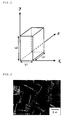
- Fig. 1 is a schematic diagram of the particulate alkali metal niobate having a rectangular cuboid shape.
- the length of a side along the x-direction is represented as L1
- the length of a side along the y-direction is represented as L2
- the length of a side along the z-direction is represented as L3.
- the lengths satisfy the relation: L1 ⁇ L3 ⁇ L2.
- the L max corresponds to L2
- the L min corresponds to L1 in Fig. 1 .
- the particle of the present invention has the length L2 of within the range of 0.10 to 25 ⁇ m
- the L max is preferably 0.10 to 20 ⁇ m.
- the L min is preferably 0.050 to 10 ⁇ m, more preferably 0.050 to 4 ⁇ m, and further preferably 0.050 to 2 ⁇ m. Furthermore, it is particularly preferably 0.050 to 1.5 ⁇ m.
- the alkali metal niobate is potassium niobate
- particles with smaller size can be produced.
- rectangular cuboid particles with the length of each side of within about 0.050 to 1.5 ⁇ m can be obtained.
- any method can be used to determine the lengths of sides of the particle and the L max and L min of the substantially rectangular cuboid particles, and the method is not particularly limited.
- the lengths of sides, L max , and L min can be determined, for example, in the following manner: Firstly, a microphotographic image of the particulate alkali metal niobate is taken using a scanning electron microscopy (SEM), and then the lengths of sides of each particle are read out from the image.
- SEM scanning electron microscopy
- variation of particle sizes is small over the whole of powdery alkali metal niobate (which is the same meaning as particulate alkali metal niobate).
- at least 80% of the total rectangular cuboid particles in the powder have a length of each side of the rectangular cuboid of within the range of 0.050 to 25 ⁇ m.
- the ratio is more preferably at least 90%, and still more preferably at least 95%.
- a ratio L max /L min (the ratio of the length of the longest side to the length of the shortest side in the substantially rectangular cuboid) is within the range of 1 to 5.
- L max corresponds to L2
- L min corresponds to L1.
- the feature the ratio L max /L min is within the range of 1 to 5" has the same meaning as that the ratio L2/L1 is within the range of 1 to 5 in Fig.1 .
- the ratio L max /L min is preferably 1 to 3, more preferably 1 to 2, still more preferably 1 to 1.5, and particularly preferably 1.
- the method of preparing particulate alkali metal niobate is not particularly limited.
- the method described above, which is a first aspect of the present invention, is preferable as the method of preparing the particulate alkali metal niobate.
- the method is innovative in that the particle size can be controlled simply by a chemical process, and no physical processes such as grinding are necessary. Thus, the method is advantageous in that production processes can be simplified as compared to conventional methods.
- the method according to a first aspect of the present invention can control the size of particles, and prevent agglomeration of the particles, while it is generally difficult to control variation in particle size in physical grinding or the like conventional method.
- the method of a first aspect of the present invention is preferable as a method for preparing particulate alkali metal niobate.
- a third aspect of the present invention relates to a piezoelectric ceramic material including the particulate alkali metal niobate.
- a method to produce the piezoelectric ceramic material is not particularly limited.
- the piezoelectric ceramic material may be produced by mixing dried particulate alkali metal niobate with required additives such as an organic binder, a dispersant, a plasticizer, and a solvent, to prepare a composition. Then, an article is molded from the composition through a known molding method, and the article is sintered at a high temperature (about 1,000oC). Examples of such a known molding method include press molding or molding using a mold.
- piezoelectric elements such as a piezoelectric buzzer and a piezoelectric transducer can be produced.
- the present invention will be described in more detail based on the following examples. It is to be noted that the present invention is not limited to these examples.
- the unit "M" which is used to refer to a concentration of an alkali or acid solution, means mol/L unless otherwise indicated.
- the solution was transferred into a 200-mL volumetric flask, and a 0.10-M aqueous HC1 solution was further added to the flask for adjusting the total volume of the solution to be 200 mL.
- a 0.50-M aqueous NbCl 5 solution in 0.10 M HCl was thus prepared.
- the solid matter was separated again by centrifugation and dried to separate particulate sodium niobate.
- the size and shape of the obtained solid particles were observed by a scanning electron microscope (SEM, manufactured by HITACHI, Ltd., S-4800), and the crystal structure of the solid particles was evaluated by X-ray diffraction (XRD, manufactured by Rigaku Corporation, Ultima-IV, 40 kV, 40 mA).
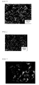
- Figs. 2 and 3 show a SEM image and an XRD pattern of the obtained NaNbO 3 particles, respectively. Results of the evaluation found that the particles were cubic particles having the length of one side of about 2 ⁇ m, and that particles consisted of single phase NaNbO 3 .
- the particles can be obtained when the temperature during the second heating step is set to 200oC.
- the particle size may be controlled such that the length of the longest side should fall within the range of 0.10 to 25 ⁇ m, and the length of the shortest side should fall within the range of 0.050 to 15 ⁇ m.
- Figs. 4 and 5 show the SEM images of the obtained KNbO 3 particles. As shown in the SEM images, cubic particles having sides of about 1 ⁇ m was obtained. Also, XRD analysis of the cubic particle was carried out, and the analysis found that particles consisted of single phase KNbO 3 .
- step (C) when the temperature during the second heating step (step (C)) was set to 150oC, cubic KNbO 3 particles with a narrow particle size distribution of about 0.2 ⁇ m, as shown in Fig. 6 , were obtained, although product yield was slightly lowered.
- the solid matter was separated from the resulting suspension by centrifugation, and then the solid was dispersed in water under ultrasonic dispersing. The solid matter was separated again by centrifugation and dried to separate NaNbO 3 particles. Evaluation of the obtained particles was performed in the same manner as that described in Example 1.
- the size of the substantially rectangular cuboid particles may be controlled such that the lengths of the sides should fall within the range of 0.50 to 25 ⁇ m.
- Fig. 7 shows a SEM image of the obtained KNbO 3 particles. The image shows that the particles had a cuboid shape with the lengths of the sides of about 0.5 ⁇ m. Moreover, the XRD analysis of the obtained particles found that the articles were KNbO 3 particles having an orthorhombic crystal structure.
- Particulate sodium niobate was obtained in the same manner as in Example 5, except that the step of allowing to still stand with heating at 100oC for 24 hours was omitted.
- the size and shape of the obtained solid particles were observed by a scanning electron microscope, and the crystal structure of the solid particles was evaluated by X-ray diffraction.
- Fig. 9 shows the SEM image of the obtained particles.
- Example 5 Comparison of Example 5 with Comparative Example 1 found that the pre-heating treatment at 100oC contributed to produce uniform-size substantially cubic NaNbO 3 particles while preventing agglomeration. According to the result of the XRD analysis, both of the particles shown in Figs. 8 and 9 consisted of single phase NaNbO 3 .
- Fig. 10 and 11 show the SEM image of the synthesized particles.
- Fig. 12 shows the result of the XRD analysis. The particles were in a cubic shape. The diffraction pattern indicated that the obtained particles consisted of KNbO 3 rhombohedral crystal.
- the KNbO 3 particles prepared in Example 2 were pelletized and then sintered at various different sintering temperatures.
- the piezoelectric properties of the obtained ceramics were evaluated. Table 1 shows values of the properties.
- the "sintering temp.” refers to sintering temperatures
- the " ⁇ ” refers to a sintering density, which was calculated based on the size (volume) and weight of the particles.
- the "tan ⁇ ” refers to a dielectric loss measured with an impedance analyzer.
- the " ⁇ 33 T / ⁇ 0 " refers to a dielectric constant measured with an impedance analyzer.
- the "Kp” refers to an electromechanical coupling coefficient, which was calculated based on values of resonance frequency and antiresonance frequency measured with an impedance analyzer.
- the "Np” refers to a frequency constant calculated based on a value of resonance frequency measured with an impedance analyzer and element diameter
- the "d33” refers to a piezoelectric constant measured with a d33 meter.
- the KNBO 3 ceramics obtained in the present invention showed high piezoelectric properties. Especially in the case where the sintering temperature was set to 1,020oC, an high piezoelectric property as d33 of 133.4 was achieved.
- the production method of the present invention is a method to provide fine particulate alkali metal niobate directly and simply by a chemical process, which does not need any physical processes such as grinding.
- substantially rectangular cuboid particles can be provided by a liquid phase. Agglomeration of the particles can be prevented due to the substantially rectangular cuboid shape, and thereby fine particles with small variation in particle sizes can be produced.
- the particles thus obtained are micrometer-order-size particles with easy handleability, and such particles can be suitably used as a piezoelectric material.
Landscapes
- Chemical & Material Sciences (AREA)
- Engineering & Computer Science (AREA)
- Organic Chemistry (AREA)
- Materials Engineering (AREA)
- Ceramic Engineering (AREA)
- Inorganic Chemistry (AREA)
- Manufacturing & Machinery (AREA)
- Nanotechnology (AREA)
- Structural Engineering (AREA)
- Physics & Mathematics (AREA)
- Composite Materials (AREA)
- Condensed Matter Physics & Semiconductors (AREA)
- General Physics & Mathematics (AREA)
- Crystallography & Structural Chemistry (AREA)
- Inorganic Compounds Of Heavy Metals (AREA)
Abstract
Description
- The present invention relates to a method of producing particulate alkali metal niobate, and particulate alkali metal niobate.
- Piezoelectric ceramics have significantly contributed to downsizing and sophistication of electronic devices. In addition to applications to conventional devices such as sensors or ultrasonic transducers, piezoelectric ceramics are recently used, for example, as a raw material of transformers for LCD backlights of personal computers or a raw material of head parts of ink jet printers.
- Lead-based materials such as PZT-based materials prevail nowadays as such piezoelectric ceramic devices. However, lead-based materials contain large amounts of harmful lead oxide, and thus, for example, environmental pollution by spilled lead oxide on disposal has been a matter of concern. Therefore, development has been strongly demanded for lead-free piezoelectric ceramic materials which can be used for alternatives to conventional lead based materials.
- Recently, alkali niobate piezoelectric ceramics draw attention as lead-free ceramic materials, which exhibit relatively high piezoelectricity. Patent Document 1, for example, proposes a piezoelectric ceramic including a solid solution mainly composed of lithium sodium niobate, together with minor components as aluminum oxide and iron oxide.
Patent Document 2 proposes an improved composition for a piezoelectric ceramic, which includes potassium niobate and sodium niobate, as main components, and copper, lithium, and tantalum, as additional components. - As a method of producing such piezoelectric ceramics, a method called a solid phase method has been widely known. The solid phase method typically includes mechanically mixing or kneading plural kinds of particulate materials as raw materials, then pelletizing, and calcining the obtained pellets.
- In recent years, liquid phase methods of synthesizing NaNbO3 particles have also been studied. For example, Non-Patent Document 1 reports a method of synthesizing NaNbO3 particles by reacting NaOH or KOH solution with Nb2O5 particles.
- Another technique has been recently reported on a method for producing particulate KNbO3 by once synthesizing layered K4Nb6O17 particles, and then heating the particles at a high temperature in a molten salt (Non-Patent Document 2).
-
- [Patent Document 1]
JP 60-52098 B - [Patent Document 2]
JP 2000-313664 A -
- [Non-Patent Document 1] C. Sun et al., European Journal of Inorganic Chemistry, 2007, 1884
- [Non-Patent Document 2] Y. Saito et al., Journal of the European Ceramic Society, 27 (2007) 4085
- However, solid phase methods are disadvantageous in that nanoscale uniform mixing of raw material particles is generally difficult because commonly available raw material particles often have a larger size, like about several millimeters to several micrometers. When raw material particles are calcined at a high temperature, the original crystal structure of the raw material changes into perovskite crystal structure. Thus, it is difficult to precisely control crystallite size and grain boundaries in a solid phase method. Control of grain boundaries is especially indispensable for enhancing properties of piezoelectric ceramics because grain boundaries significantly affect some properties such as piezoelectric properties or strength. Therefore, use of a material in which control of grain boundaries are insufficient may lead to problems such as defects of products and deterioration of properties.
- Conventional liquid phase methods may cause particle agglomeration. Also, it is generally difficult to control the size and shape of particles in a uniform state by a conventional liquid phase method. For example, particles produced by the method described in Patent Document 1 are given as aggregates, and are not suitable as a material to form piezoelectric devices, for which downsizing has been recently demanded.
- The method described in
Patent Document 2 also requires some improvement in that control of the particle size is actually impossible or that multi-step synthesis is required. - In view of the current state, there has been a demand for developing a method of producing particulate alkali metal niobate, which is suitable for mass production, can prevent agglomeration of particles, and can control the grain boundaries and particle size. Further, there has been a demand for fine particulate alkali metal niobate having a highly uniform particle size.
- The present invention has an object to provide a liquid phase method of producing fine particulate alkali metal niobate which can control the size and shape of the fine particulate alkali metal niobate. The present invention has another object to provide fine particulate alkali metal niobate having controlled shape and size, and a lead-free niobium-containing ceramic material having high piezoelectricity.
- A first aspect of the present invention relates to a method of producing particulate alkali metal niobate represented by MNbO3 (1)
wherein M represents one element selected from alkaline metals, the particulate alkali metal niobate having a substantially rectangular cuboid shape,
the method including the steps of: - (a) mixing a niobium-containing solution with an alkaline solution having a concentration of 0.1 to 30 mol/L, to prepare a suspension;
- (b) still standing the suspension at between 80ºC and 150ºC for 12 to 48 hours;
- (c) performing solvothermal reaction of the suspension at between 150ºC and 300ºC for 1 to 12 hours; and
- (d) separating the particulate alkali metal niobate from a reaction mixture.
- In a preferred embodiment, M in the formula (1) is Na, and the alkaline solution is NaOH.
- In another preferred embodiment, M in the formula (1) is K, and the alkaline solution is KOH.
- In another preferred embodiment, the niobium-containing solution includes:
- niobium oxide and/or niobium halide;
- a solvent selected from the group consisting of water, ethylene glycol, and polyethylene glycol; and
- an acid.
- A second aspect of the present invention relates to particulate alkali metal niobate represented by the formula (1) :
MNbO3 (1)
wherein M represents one element selected from alkaline metals, the particulate alkali metal niobate having a substantially rectangular cuboid shape,
wherein the substantially rectangular cuboid shape has a longest side and a shortest side,
the length of the longest side represented by an index Lmax is 0.10 to 25 µm, and
the length of the shortest side represented by an index Lmin is 0.050 to 15 µm. - In a preferred embodiment, the ratio of the Lmax to the Lmin, Lmax/Lmin, is within the range of 1 to 5.
- In another preferred embodiment, M in the formula (1) is Na or K.
- In yet another preferred embodiment, the particulate alkali metal niobate is prepared by the above method.
- A third aspect of the present invention relates to a piezoelectric ceramic material that comprises the particulate alkali metal niobate.
- According to the production method of the present invention, particulate alkali metal niobate, preferably fine particulate NaNbO3 or KNbO3 can be synthesized in a large scale while controlling the size and shape. Resulting particles have a unique shape of substantially rectangular cuboid, more preferably substantially cubic, and the size and shape are well controlled. The method of the present invention is advantageous because the method gives practically favorable sub-micron to several micrometer particles in a manner suitable for mass production.
- In addition, ceramic materials obtained by pelletizing the niobate particles and calcining the resultant pellet is more advantageous than niobium-based piezoelectric ceramic materials obtained by conventional solid phase methods in the following points:
- 1. Low-temperature calcination is practicable;
- 2. Excellent piezoelectric properties will be exhibited;
- 3. Densification of ceramic materials are easily achievable; and
- 4. Slurry preparation prior to production of layered articles is easy.
-
-
Fig. 1 illustrates a schematic diagram for explaining of the particulate alkali metal niobate of the present invention having a substantially rectangular cuboid shape. -
Fig. 2 shows a SEM image of particulate NaNbO3 synthesized in Example 1. -
Fig. 3 shows XRD (X-ray diffraction) pattern of the particulate NaNbO3 synthesized in Example 1. -
Fig. 4 shows a SEM image of particulate KNbO3 synthesized in Example 2. -
Fig. 5 shows a SEM image of particulate KNbO3 synthesized in Example 2 (Magnified image of theFig. 4 ). -
Fig. 6 shows a SEM image of fine particulate KNbO3 synthesized in Example 2 (temperature at secondary heating: 150ºC). -
Fig. 7 shows a SEM image of particulate KNbO3 synthesized in Example 4 (starting material: niobium oxide). -
Figure 8 shows a SEM image of particulate NaNbO3 prepared in Example 5 (heated at 100ºC). -
Fig. 9 shows a SEM image of particulate NaNbO3 prepared in Comparative Example 1 (not heated at 100ºC). -
Fig. 10 shows a SEM image of particulate KNbO3 synthesized in Example 6 (large scale synthesis). -
Fig. 11 shows a SEM image of particulate KNbO3 synthesized in Example 6 (Magnified image of theFig. 10 ). -
Fig. 12 shows an XRD pattern of particulate KNbO3 synthesized in Example 6 (large scale synthesis). - The present invention will be explained in detail below.
- As mentioned above, a first aspect of the present invention relates to a method of producing particulate alkali metal niobate represented by the formula:
MNbO3 (1)
wherein M represents one element selected from alkaline metals, the particulate alkali metal niobate having a substantially rectangular cuboid shape,
the method including the steps of: - (a) mixing a niobium-containing solution with an alkaline solution having a concentration of 0.1 to 30 mol/L, to prepare a suspension;
- (b) still standing the suspension at between 80ºC and 150ºC for 12 to 48 hours;
- (c) performing solvothermal reaction of the suspension at between 150ºC and 300ºC for 1 to 12 hours; and
- (d) separating the particulate alkali metal niobate from a reaction mixture.
- In the formula (1), Mis an alkaline metal. Specifically, M is an element selected from the group consisting of lithium (Li), sodium (Na), potassium (K), rubidium (Rb), and cesium (Cs). Preferably, M is Li, Na, or K, and more preferably Na or K. In particular, M is preferably K because obtained particles are small in size, and have a highly uniform close-to-cube shape.
- In the following, each step is described.
The step (a) is for preparing a suspension by mixing a niobium-containing solution as a niobium source with a high-concentration alkaline solution. - The method to prepare a niobium-containing solution is not particularly limited. For example, such a solution can be prepared by dissolving a niobium compound in an acidic liquid solvent. Preferably, such a niobium compound may be, but not limited to, at least one of niobium oxide and niobium halides. Examples of the niobium halides include niobium fluoride, niobium chloride, niobium bromide, and niobium iodide. In view of handling ability and reactivity, niobium chloride is preferable among the niobium halide. Niobium compounds may be used alone or in combination of two or more of these.
- Solvents to be contained in the above acidic liquid solvent are not particularly limited. Examples thereof include water, alcohols such as methyl alcohol and ethyl alcohol, and polyols such as ethylene glycol (EG), glycerol, and polyethylene glycol (PEG). Of these, water, ethylene glycol, and polyethylene glycol, as well as a mixture of these, are preferable in view of relatively high boiling points and applicability to solvothermal reaction. Water is particularly preferable.
- The acid to be contained in the above acidic liquid solvent is not particularly limited. Examples thereof include inorganic acids such as hydrochloric acid, sulfuric acid, and nitric acid, and organic acids such as trifluoroacetic acid. Of these, hydrochloric acid and nitric acid are preferable in that they are easily removable after the reaction. Hydrochloric acid is particularly preferable.
- Then, the alkaline solution to be used in the step (a) is described.
In the present invention, the alkaline solution is not particularly limited as long as it satisfies required high concentration. However, such an alkaline metal normally a source of the "M" in the particulate alkali metal niobate MNbO3 and thus, specifically, the alkaline metal is preferably an alkali metal hydroxide represented by the following formula (2) :
MOH (2)
wherein M is the same as defined in formula (1). NaOH or KOH is particularly preferred among them. - The solvent contained in the alkaline solution is not particularly limited, and may be water, alcohol, diol, triol, or acetone. Of these, water is preferred.
- The alkaline solution to be used in the present invention has such a high concentration as 0.1 to 30 mol/L. The concentration is equivalent to that of a very-high-concentration alkaline solution having a pH of about 13 or higher. That is, assuming that the degree of ionization of a strong base (such as NaOH and KOH) is 1 irrespective of the concentration of the alkaline solution, the pH of a "0.1 mol/L" alkaline solution corresponds to 13, as follows:



- An alkaline solution having a concentration of less than 0.1 mol/L is undesirable because particles may not grow sufficiently, and thus particles with a desired size and shape may not be produced. In contrast, if the concentration exceeds 30 mol/L, an alkaline solution usually reaches saturation. Thus, the upper limit of the concentration of the alkaline solution herein actually means a saturation concentration of the alkaline solution, and this upper limit may vary depending on the nature of the alkali. The lower limit of the concentration of the alkaline solution is preferably 1 mol/L, and more preferably 2 mol/L. The alkaline solution used herein is a fairly high concentration solution. Therefore, much attention is required to handle the solution. The reaction vessel for step (a) is preferably, but is not limited to, a corrosion-resistant vessel made of, for example, Teflon (TM).
- The niobium-containing solution and the alkali solution prepared separately in the above-mentioned manner are mixed together to prepare a suspension. The way of addition of the solutions is not particularly limited. For example, the niobium-containing solution may be added to the alkaline solution, or the alkaline solution may be added to the niobium-containing solution. In view of safety, it is preferable to slowly add a niobium-containing solution dropwise into the alkaline solution over a sufficient period of time. Temperature and pressure during the mixing are not particularly limited. Usually, the mixing may be carried out at an ordinary temperature (15ºC to 30ºC) under an ordinary pressure (about 1 atm).
- Next, the step (b) is described.
The step (b) is a step of heating the suspension at a relatively low temperature over a long period of time. The method of the present invention is characterized by including two steps, namely, a step of heating the suspension at a relatively low temperature over a long period of time, and a step of performing solvothermal reaction at a high temperature for a short period of time. If the step (b) is omitted, aggregates are normally generated, so the particle size cannot be sufficiently controlled. Also, if the step (b) is omitted, particles having a substantially rectangular cuboid shape cannot be produced, which impairs a characteristic of the present invention. - In the step (b), the suspension is heated to a temperature of between 80ºC to 150ºC. Keeping this temperature constant for a certain period of time gives a uniform precursor, and encourages the particles to grow into a substantially rectangular cuboid shape. The temperature on heating is preferably 80ºC to 120ºC, more preferably 90ºC to 110ºC, and still more preferably the boiling point of a solvent. If water is used as the solvent, the suspension is preferably heated to 100ºC.
- The step (b) is characterized by allowing the suspension to still stand at a specific temperature for 12 to 48 hours. Such still standing step for a while helps to produce a uniform precursor solution or suspension suitable for particle growth, and promotes growth of particle into a substantially rectangular cuboid shape. If the period for still standing is too short, growth into uniform precursors may be insufficient. In contrast, if the period is too long, the effects may be saturated and the step is not advantageous from an economical viewpoint. Therefore, an appropriate period of still standing is 12 to 48 hours. The period of still standing is preferably 15 to 36 hours, more preferably 18 to 30 hours, and still more preferably 20 to 26 hours.
- While the pressure during the step (b) is not particularly limited, the step is usually performed under an ordinary pressure (about 1 atm (= about 0.10 MPa)).
- Next, the step (c) is described.
The step (c) is a step of subjecting the suspension which was heated at a relatively low temperature in the step (b) to solvothermal reaction at a high temperature. - The solvothermal reaction is a reaction performed under a moderate to high degree of pressure (normally 1 to 10, 000 atm (= 0.10 to 1,000 MPa)) and temperature (normally 100ºC to 1,000ºC). When water is used as a solvent, the solvothermal reaction is specially referred to as "hydrothermal reaction". By performing this process, crystal structures and particle shape can be controlled.
- In the present invention, the solvothermal reaction is performed at a temperature of between 150ºC and 300ºC. While not particularly limited, the temperature is preferably 150ºC to 250ºC.
- The period of time for the solvothermal reaction is not particularly limited, and is usually 1 to 72 hours, preferably 1 to 8 hours, and more preferably 2 to 5 hours.
- The pressure during the solvothermal reaction is not particularly limited, and is usually 0.10 to 4.0 MPa.
- Next, the step (d) is described.
The step (d) is a step to separate the particulate alkali metal niobate from the reaction product of the solvothermal reaction. - The method to separate the particulate alkali metal niobate is not particularly limited. Desired particulate alkali metal niobate can be separated through normal processes such as filtration, washing, and drying. The number of times of washing, solvents to be used for washing, and other conditions are not particularly limited, and may be appropriately selected.
- Particulate alkali metal niobate, which is a second aspect of the present invention, is described. The particulate alkali metal niobate of the invention is particulate alkali metal niobate represented by the following formula (1):
MNbO3 (1)
wherein M represents one element selected from alkaline metals. The alkali metal niobate have a substantially rectangular cuboid shape. The substantially rectangular cuboid shape has a longest side and a shortest side. Assuming that the length of the longest side is represented by an index Lmax, and the length of the shortest side is represented by an index Lmin, the Lmax is 0.10 to 25 µm, and the Lmin is 0.050 to 15 µm. - The M in the above formula (1) is specifically one element selected from lithium (Li), sodium (Na), potassium (K), rubidium (Rb), and cesium (Cs). Li, Na, or K is preferable, and Na or K is more preferable. The M is particularly preferably K because the particles of KNbO3 have a uniform size and shape.
- The particulate alkali metal niobate of the present invention is characterized in that the shape of the particles is rectangular cuboid, and their size and shape are highly uniform. The shape of the particulate alkali metal niobate can be controlled in a simple chemical process, and no physical grinding process is necessary. Furthermore, the shape of resulting particles is not a spherical, which is common for particles, but a unique, substantially rectangular cuboid shape. Such features are not expectable from the conventional knowledge.
- The particulate alkali metal niobate of the present invention is in a fine, substantially rectangular cuboid shape. Particulate alkali metal niobate obtained by a conventional method is generally in an aggregate form. Therefore, it has been difficult to produce micrometer-order-size particles. The present invention successfully produces
micrometer-order-size particles with some advantages such as easy handleability by controlling the shape of particulate alkali metal niobate to be in a substantially rectangular cuboid form, thereby preventing generation of aggregates. - The particles having the shape mentioned above may be packed more densely than sphere particles or aggregated
particles. Thus, gap among particles can be reduced on packing the particles. The particulate alkali metal niobate is thus advantageous in that a ceramic material of the present invention made from particulate alkali metal niobate may become dense. - Herein, the term "rectangular cuboid" includes an essentially rectangular cuboid shape and a cube shape. Further, the term "rectangular cuboid" includes a rectangular cuboid shape with partly chipped portions, or a rectangular cuboid shape with uneven surfaces, too.
- The rectangular cuboid has an Lmax, the length of the longest side, of 0.10 to 25 µm, and an Lmin, the length of the shortest side, of 0.050 to 15 µm. A rectangular cuboid generally has 12 sides, which are represented as widths, depths, and heights. The particulate alkali metal niobate of the present invention shows particles well-controlled size, and has a substantially rectangular cuboid shape with the length of the longest side of 0.10 to 25 µm and the length of the shortest side of 0.050 to 15 µm.
- This feature is further described with reference to the drawings.
Fig. 1 is a schematic diagram of the particulate alkali metal niobate having a rectangular cuboid shape. InFig. 1 , the length of a side along the x-direction is represented as L1, the length of a side along the y-direction is represented as L2, and the length of a side along the z-direction is represented as L3. Here, the lengths satisfy the relation: L1 < L3 < L2. Thus, the Lmax corresponds to L2, and the Lmin corresponds to L1 inFig. 1 . Referring toFig. 1 , the particle of the present invention has the length L2 of within the range of 0.10 to 25 µm, and the length L1 of within the range of 0.050 to 15 µm. - The Lmax is preferably 0.10 to 20 µm.
- The Lmin is preferably 0.050 to 10 µm, more preferably 0.050 to 4 µm, and further preferably 0.050 to 2 µm. Furthermore, it is particularly preferably 0.050 to 1.5 µm.
- In particular, in the case where the alkali metal niobate is potassium niobate, particles with smaller size can be produced. Specifically, rectangular cuboid particles with the length of each side of within about 0.050 to 1.5 µm can be obtained.
- Any method can be used to determine the lengths of sides of the particle and the Lmax and Lmin of the substantially rectangular cuboid particles, and the method is not particularly limited. The lengths of sides, Lmax, and Lmin can be determined, for example, in the following manner: Firstly, a microphotographic image of the particulate alkali metal niobate is taken using a scanning electron microscopy (SEM), and then the lengths of sides of each particle are read out from the image.
- Also, it is one of the characteristics of the present invention that variation of particle sizes is small over the whole of powdery alkali metal niobate (which is the same meaning as particulate alkali metal niobate). Preferably, at least 80% of the total rectangular cuboid particles in the powder have a length of each side of the rectangular cuboid of within the range of 0.050 to 25 µm. The ratio is more preferably at least 90%, and still more preferably at least 95%.
- In a preferred embodiment of the present invention, a ratio Lmax/Lmin (the ratio of the length of the longest side to the length of the shortest side in the substantially rectangular cuboid) is within the range of 1 to 5.
- Referring to
Fig. 1 , Lmax corresponds to L2, and Lmin corresponds to L1. Thus, the feature the ratio Lmax/Lmin is within the range of 1 to 5" has the same meaning as that the ratio L2/L1 is within the range of 1 to 5 inFig.1 . - The ratio Lmax/Lmin is preferably 1 to 3, more preferably 1 to 2, still more preferably 1 to 1.5, and particularly preferably 1. A state that satisfies the relation, "the ratio Lmax/Lmin is 1", means that the shape of a particle is cubic.
- The method of preparing particulate alkali metal niobate is not particularly limited. The method described above, which is a first aspect of the present invention, is preferable as the method of preparing the particulate alkali metal niobate. The method is innovative in that the particle size can be controlled simply by a chemical process, and no physical processes such as grinding are necessary. Thus, the method is advantageous in that production processes can be simplified as compared to conventional methods. In addition, the method according to a first aspect of the present invention can control the size of particles, and prevent agglomeration of the particles, while it is generally difficult to control variation in particle size in physical grinding or the like conventional method. As a result, particles with highly-controlled size can be obtained by the method according to a first aspect of the present invention. Because of these reasons, the method of a first aspect of the present invention is preferable as a method for preparing particulate alkali metal niobate.
- A third aspect of the present invention relates to a piezoelectric ceramic material including the particulate alkali metal niobate.
- A method to produce the piezoelectric ceramic material is not particularly limited. Generally, the piezoelectric ceramic material may be produced by mixing dried particulate alkali metal niobate with required additives such as an organic binder, a dispersant, a plasticizer, and a solvent, to prepare a composition. Then, an article is molded from the composition through a known molding method, and the article is sintered at a high temperature (about 1,000ºC). Examples of such a known molding method include press molding or molding using a mold.
- Then, by forming electrodes on a molded body obtained from the piezoelectric ceramic material, piezoelectric elements such as a piezoelectric buzzer and a piezoelectric transducer can be produced.
- The present invention will be described in more detail based on the following examples. It is to be noted that the present invention is not limited to these examples. In the examples and comparative examples below, the unit "M", which is used to refer to a concentration of an alkali or acid solution, means mol/L unless otherwise indicated.
- A portion of 27.02 g (= 100 mmol) of niobium chloride was completely dissolved in 150 mL of a 0.10-M aqueous HC1 solution. The solution was transferred into a 200-mL volumetric flask, and a 0.10-M aqueous HC1 solution was further added to the flask for adjusting the total volume of the solution to be 200 mL. A 0.50-M aqueous NbCl5 solution in 0.10 M HCl was thus prepared. Then, 6.0 mL of the 0.50-M aqueous NbCl5 solution in 0.10 M HCl was slowly added to 6.0 mL of a 12.0-M aqueous NaOH solution in a 30-mL Teflon (TM) vessel at room temperature under stirring. The resulting white suspension was allowed to still stand with heating at 100ºC in the Teflon (TM) vessel for 24 hours. Then, the content was transferred to an autoclave whose inner chamber wall was made of Teflon (TM), and allowed to stand for 3 hours with heating at 250ºC. The solid matter was separated from the resulting suspension by centrifugation, and then the solid was dispersed in water under ultrasonic dispersing. The solid matter was separated again by centrifugation and dried to separate particulate sodium niobate. The size and shape of the obtained solid particles were observed by a scanning electron microscope (SEM, manufactured by HITACHI, Ltd., S-4800), and the crystal structure of the solid particles was evaluated by X-ray diffraction (XRD, manufactured by Rigaku Corporation, Ultima-IV, 40 kV, 40 mA).
Figs. 2 and3 show a SEM image and an XRD pattern of the obtained NaNbO3 particles, respectively. Results of the evaluation found that the particles were cubic particles having the length of one side of about 2 µm, and that particles consisted of single phase NaNbO3. Alternatively, the particles can be obtained when the temperature during the second heating step is set to 200ºC. By adjusting the initial NaOH concentration to 2 to 18 mol/L, the particle size may be controlled such that the length of the longest side should fall within the range of 0.10 to 25 µm, and the length of the shortest side should fall within the range of 0.050 to 15 µm. - Synthesis of substantially cubic KNbO3 particles was performed in the same manner as in Example 1, except that an 18.0-M aqueous KOH solution was used in place of the 12.0-M aqueous NaOH solution.
Figs. 4 and5 show the SEM images of the obtained KNbO3 particles. As shown in the SEM images, cubic particles having sides of about 1 µm was obtained. Also, XRD analysis of the cubic particle was carried out, and the analysis found that particles consisted of single phase KNbO3.
Alternatively, when the temperature during the second heating step (step (C)) was set to 150ºC, cubic KNbO3 particles with a narrow particle size distribution of about 0.2 µm, as shown inFig. 6 , were obtained, although product yield was slightly lowered. - A portion of 6.0 mL of an 8.0-M aqueous NaOH solution was added to 0.40 g (= 3.0 mmol) of niobium pentoxide in a 30-mL Teflon (TM) vessel. Ion-exchange water was further added to the vessel under stirring to adjust the total volume of the mixture to 12 mL. Then, the Teflon (TM) vessel was sealed and allowed to still stand with heating at 100ºC for 24 hours. Then, the content was transferred to an autoclave whose inner chamber wall was made of Teflon (TM), and allowed to stand for 3 hours with heating at 250ºC. The solid matter was separated from the resulting suspension by centrifugation, and then the solid was dispersed in water under ultrasonic dispersing. The solid matter was separated again by centrifugation and dried to separate NaNbO3 particles. Evaluation of the obtained particles was performed in the same manner as that described in Example 1. By adjusting the initial concentration of NaOH to 5 to 18 mol/L, the size of the substantially rectangular cuboid particles may be controlled such that the lengths of the sides should fall within the range of 0.50 to 25 µm.
- Synthesis of substantially cubic KNbO3 particles using niobium pentoxide as a starting material was performed in the same heating procedures and washing operation as those in Example 3, except that a KOH solution or particulate KOH was added in place of the aqueous NaOH solution to control the alkaline ion concentration to 18 M.
Fig. 7 shows a SEM image of the obtained KNbO3 particles. The image shows that the particles had a cuboid shape with the lengths of the sides of about 0.5 µm. Moreover, the XRD analysis of the obtained particles found that the articles were KNbO3 particles having an orthorhombic crystal structure. - A portion of 6.0 mL of the 0.50-M aqueous NbCl5 solution in 0.10 M HCl was added to 6.0 mL of a 8.0- M NaOH solution under stirring to prepare a white suspension. The white suspension was allowed to still stand with heating at 100ºC for 24 hours in a Teflon (TM) vessel. The content was transferred to an autoclave whose inner chamber wall was made of Teflon (TM), and allowed to stand for 3 hours with heating at 250ºC. Then, the solid matter was separated from the resulting suspension by centrifugation, and then the solid was dispersed in water under ultrasonic dispersing. The solid matter was separated again by centrifugation and dried to separate particulate sodium niobate. The size and shape of the obtained solid particles were observed by a scanning electron microscope, and the crystal structure of the solid particles was evaluated by X-ray diffraction.
Fig. 8 shows the SEM image of the obtained NaNbO3 particles. - Particulate sodium niobate was obtained in the same manner as in Example 5, except that the step of allowing to still stand with heating at 100ºC for 24 hours was omitted. The size and shape of the obtained solid particles were observed by a scanning electron microscope, and the crystal structure of the solid particles was evaluated by X-ray diffraction.
Fig. 9 shows the SEM image of the obtained particles. - Comparison of Example 5 with Comparative Example 1 found that the pre-heating treatment at 100ºC contributed to produce uniform-size substantially cubic NaNbO3 particles while preventing agglomeration. According to the result of the XRD analysis, both of the particles shown in
Figs. 8 and 9 consisted of single phase NaNbO3. - To an alkaline solution (36 M KOH solution, 185 mL) put in a Teflon (TM) vessel, 185 mL of an dispersion containing 12.3 g of Nb2O5 was added dropwise at a rate of 15 mL/min under stirring. The thus-obtained mixed suspension was stirred for 10 minutes in a Teflon (TM) vessel. The resultant suspension was transferred to an autoclave whose inner chamber wall was made of Teflon (TM). The suspension was heated up to 100ºC over 30 minutes under stirring, and was then stirred at 100ºC for 24 hours. Next, the suspension was heated up to 200ºC over two and a half hours, followed by heating at 200ºC for three hours under stirring. After the heating, the suspension was naturally cooled. The solid matter was separated from the resulting suspension by centrifugation. Then, the solid matter was dispersed in water under ultrasonic dispersing, separated by centrifugal segmentation, and decantation. This washing process including ultrasonic dispersing, centrifugal segmentation, and decantation was repeated six times. Washing by centrifugation was further made three times using acetone as a washing liquid, followed by drying in a desiccator. Thereby, particulate sodium niobate was obtained. The size and shape of the obtained solid particles were observed by a scanning electron microscope, and the crystal structure of the solid particles was evaluated by X-ray diffraction.
Figs. 10 and11 show the SEM image of the synthesized particles.Fig. 12 shows the result of the XRD analysis. The particles were in a cubic shape. The diffraction pattern indicated that the obtained particles consisted of KNbO3 rhombohedral crystal. - The KNbO3 particles prepared in Example 2 were pelletized and then sintered at various different sintering temperatures. The piezoelectric properties of the obtained ceramics were evaluated. Table 1 shows values of the properties.
- In Table 1, the "sintering temp." refers to sintering temperatures, the "ρ" refers to a sintering density, which was calculated based on the size (volume) and weight of the particles. The "tan δ" refers to a dielectric loss measured with an impedance analyzer. Further, the "ε33 T/ε0" refers to a dielectric constant measured with an impedance analyzer. The "Kp" refers to an electromechanical coupling coefficient, which was calculated based on values of resonance frequency and antiresonance frequency measured with an impedance analyzer. The "Np" refers to a frequency constant calculated based on a value of resonance frequency measured with an impedance analyzer and element diameter, and the "d33" refers to a piezoelectric constant measured with a d33 meter.
-
[Table 1] No. Sintering Temp. °C ρ g/cm3 tan δ % ε33 T/ ε0 Kp % Np Hz·mm d33 pC/N 1 1020 4.05 8.72 877 25.5 3220 133.4 2 1040 4.07 6.77 875 27.2 3297 120 3 1060 3.76 8.68 727 21.4 3000 83.7 - As shown in Table 1, the KNBO3 ceramics obtained in the present invention showed high piezoelectric properties. Especially in the case where the sintering temperature was set to 1,020ºC, an high piezoelectric property as d33 of 133.4 was achieved.
- The production method of the present invention is a method to provide fine particulate alkali metal niobate directly and simply by a chemical process, which does not need any physical processes such as grinding. According to the method of the present invention, substantially rectangular cuboid particles can be provided by a liquid phase. Agglomeration of the particles can be prevented due to the substantially rectangular cuboid shape, and thereby fine particles with small variation in particle sizes can be produced. The particles thus obtained are micrometer-order-size particles with easy handleability, and such particles can be suitably used as a piezoelectric material.
-
- L1: Length of a side along the x-direction
- L2: Length of a side along the y-direction
- L3: Length of a side along the z-direction
Claims (9)
- A method of producing particulate alkali metal niobate represented by
MNbO3 (1)
wherein M represents one element selected from alkaline metals, the particulate alkali metal niobate having a substantially rectangular cuboid shape,
the method comprising the steps of:(a) mixing a niobium-containing solution with an alkaline solution having a concentration of 0.1 to 30 mol/L, to prepare a suspension;(b) still standing the suspension at between 80ºC and 150ºC for 12 to 48 hours;(c) performing solvothermal reaction of the suspension at between 150ºC and 300ºC for 1 to 12 hours; and(d) separating the particulate alkali metal niobate from a reaction mixture. - The method according to claim 1,
wherein M in the formula (1) is Na, and the alkaline solution is NaOH. - The method according to claim 1,
wherein M in the formula (1) is K, and the alkaline solution is KOH. - The method according to any one of claims 1 to 3, wherein the niobium-containing solution includes:- niobium oxide and/or niobium halide;- a solvent selected from the group consisting of water, ethylene glycol, and polyethylene glycol; and- an acid.
- Particulate alkali metal niobate represented by the formula (1) :
MNbO3 (1)
wherein M represents one element selected from alkaline metals, the particulate alkali metal niobate having a substantially rectangular cuboid shape,
wherein the substantially rectangular cuboid shape has a longest side and a shortest side,
the length of the longest side represented by an index Lmax is 0.10 to 25 µm, and
the length of the shortest side represented by an index Lmin is 0.050 to 15 µm. - The particulate alkali metal niobate according to claim 5,
wherein the ratio of the Lmax to the Lmin, Lmax/Lmin, is within the range of 1 to 5. - The particulate alkali metal niobate according to claim 5 or 6,
wherein the M in the formula (1) is Na or K. - The particulate alkali metal niobate according to any one of claims 5 to 7,
wherein the particulate alkali metal niobate is prepared by the method according to any one of claims 1 to 4. - A piezoelectric ceramic material comprising the particulate alkali metal niobate according to any one of claims 5 to 8.
Applications Claiming Priority (2)
| Application Number | Priority Date | Filing Date | Title |
|---|---|---|---|
| JP2009095013A JP5582281B2 (en) | 2009-04-09 | 2009-04-09 | Process for producing alkali metal niobate particles and alkali metal niobate particles |
| PCT/JP2010/056171 WO2010116972A1 (en) | 2009-04-09 | 2010-04-05 | Method for producing alkali metal niobate particles, and alkali metal niobate particles |
Publications (3)
| Publication Number | Publication Date |
|---|---|
| EP2418174A1 true EP2418174A1 (en) | 2012-02-15 |
| EP2418174A4 EP2418174A4 (en) | 2015-04-01 |
| EP2418174B1 EP2418174B1 (en) | 2016-10-05 |
Family
ID=42936255
Family Applications (1)
| Application Number | Title | Priority Date | Filing Date |
|---|---|---|---|
| EP10761671.6A Not-in-force EP2418174B1 (en) | 2009-04-09 | 2010-04-05 | Method for producing alkali metal niobate particles, and alkali metal niobate particles |
Country Status (7)
| Country | Link |
|---|---|
| US (2) | US8771618B2 (en) |
| EP (1) | EP2418174B1 (en) |
| JP (1) | JP5582281B2 (en) |
| KR (1) | KR101642535B1 (en) |
| CN (1) | CN102369162B (en) |
| DK (1) | DK2418174T3 (en) |
| WO (1) | WO2010116972A1 (en) |
Cited By (2)
| Publication number | Priority date | Publication date | Assignee | Title |
|---|---|---|---|---|
| WO2012165267A1 (en) * | 2011-05-27 | 2012-12-06 | Canon Kabushiki Kaisha | Sodium niobate powder, method of manufacturing a sodium niobate powder, plate-like particle, method of manufacturing a plate-like particle, and method of manufacturing an oriented ceramics |
| WO2013157452A1 (en) * | 2012-04-16 | 2013-10-24 | Canon Kabushiki Kaisha | Sodium niobate powder, method for producing the same, method for producing ceramic, and piezoelectric element |
Families Citing this family (20)
| Publication number | Priority date | Publication date | Assignee | Title |
|---|---|---|---|---|
| JP5578504B2 (en) * | 2009-04-09 | 2014-08-27 | 堺化学工業株式会社 | Process for producing alkali metal niobate particles and alkali metal niobate particles |
| JP6016431B2 (en) * | 2012-04-20 | 2016-10-26 | キヤノン株式会社 | Method for producing sodium niobate fine particles |
| CN103303977B (en) * | 2013-06-07 | 2015-02-04 | 中国矿业大学 | A preparation method of hierarchical hollow Nb3O7F nanomaterials |
| EP3249704B1 (en) * | 2015-01-21 | 2020-03-04 | Alps Alpine Co., Ltd. | Piezoelectric device |
| US10461241B2 (en) | 2015-03-17 | 2019-10-29 | Canon Kabushiki Kaisha | Method for manufacturing rectangular parallelepiped-shaped single crystal, rectangular parallelepiped-shaped single crystal, method for manufacturing ceramics, ceramics, piezoelectric element, piezoelectric device, and electronic device |
| CN105126811B (en) * | 2015-07-29 | 2017-10-24 | 河南大学 | Sodium niobate photocatalytic material with specific morphology and its preparation method and application |
| US10516304B2 (en) | 2015-12-22 | 2019-12-24 | Intel Corporation | Wireless charging coil placement for reduced field exposure |
| US10411492B2 (en) | 2015-12-23 | 2019-09-10 | Intel Corporation | Wireless power transmitter shield with capacitors |
| US11239409B2 (en) | 2016-06-23 | 2022-02-01 | Nippon Chemical Industrial Co., Ltd. | Piezoelectric material filler, composite piezoelectric material, composite piezoelectric device, composite piezoelectric material filler, and method for producing alkali niobate compound |
| CN107640788A (en) * | 2017-09-25 | 2018-01-30 | 清华大学深圳研究生院 | Niobic acid salt material and preparation method thereof |
| CN108910947B (en) * | 2018-07-17 | 2020-11-03 | 天津城建大学 | A kind of thin micro-nano (K, Na) NbO3 crystal and preparation method thereof |
| CN109097043B (en) * | 2018-09-14 | 2021-07-20 | 广东工业大学 | An erbium and ytterbium double-doped sodium niobate up-conversion material and its preparation method and application |
| CN109233829B (en) * | 2018-09-14 | 2021-09-24 | 广东工业大学 | A kind of magnesium erbium ytterbium tri-doped sodium niobate and its preparation method and application |
| CN109553136B (en) * | 2018-11-15 | 2021-03-16 | 北京工业大学 | A kind of method for preparing composite alkali metal niobate powder |
| JP7206847B2 (en) * | 2018-11-22 | 2023-01-18 | 堺化学工業株式会社 | Method for producing alkali metal niobate particles |
| JP7498547B2 (en) * | 2019-06-24 | 2024-06-12 | 株式会社富士セラミックス | Niobium-based lead-free piezoelectric ceramics and their manufacturing method |
| JP7468030B2 (en) * | 2020-03-19 | 2024-04-16 | 堺化学工業株式会社 | Niobate alkali metal salt particles |
| CN111468133B (en) * | 2020-05-29 | 2022-12-27 | 陕西科技大学 | Preparation method of potassium niobate/alpha-ferric oxide heterogeneous photocatalyst |
| EP4163256A4 (en) | 2020-06-04 | 2023-12-06 | Mitsui Mining & Smelting Co., Ltd. | NIOBATE COMPOUND AND NIOBIUM-CONTAINING SLURRY |
| CN113428899B (en) * | 2021-07-28 | 2022-07-29 | 宝鸡文理学院 | Two-dimensional plate-shaped KNbO 3 Controllable preparation method of mesoscopic crystal |
Family Cites Families (11)
| Publication number | Priority date | Publication date | Assignee | Title |
|---|---|---|---|---|
| BE649820A (en) * | 1963-06-28 | |||
| JPS6052098B2 (en) | 1980-12-03 | 1985-11-18 | 三菱電機株式会社 | piezoelectric ceramic composition |
| JPS6052098A (en) | 1983-08-31 | 1985-03-23 | 松下電器産業株式会社 | Frame shielding structure |
| IT1270828B (en) * | 1993-09-03 | 1997-05-13 | Chon Int Co Ltd | PROCESS FOR THE SYNTHESIS OF CRYSTAL CERAMIC POWDERS OF PEROVSKITE COMPOUNDS |
| JP3531803B2 (en) | 1999-02-24 | 2004-05-31 | 株式会社豊田中央研究所 | Alkali metal containing niobium oxide based piezoelectric material composition |
| JP4930671B2 (en) * | 2005-04-28 | 2012-05-16 | 株式会社豊田中央研究所 | Method for producing anisotropic shaped powder |
| US7585474B2 (en) * | 2005-10-13 | 2009-09-08 | The Research Foundation Of State University Of New York | Ternary oxide nanostructures and methods of making same |
| WO2007080684A1 (en) * | 2006-01-12 | 2007-07-19 | Murata Manufacturing Co., Ltd. | Anisotropically shaped ceramic particles and process for production of the same |
| CN101249985A (en) * | 2008-03-25 | 2008-08-27 | 大连理工大学 | Controllable Preparation of Orthorhombic Phase and Trigonal Phase Sodium Niobate with High Curie Point |
| JP5578504B2 (en) * | 2009-04-09 | 2014-08-27 | 堺化学工業株式会社 | Process for producing alkali metal niobate particles and alkali metal niobate particles |
| CN104334498B (en) * | 2012-04-16 | 2016-12-21 | 佳能株式会社 | Sodium niobate powder and its preparation method, ceramic preparation method and piezoelectric element |
-
2009
- 2009-04-09 JP JP2009095013A patent/JP5582281B2/en active Active
-
2010
- 2010-04-05 KR KR1020117023556A patent/KR101642535B1/en not_active Expired - Fee Related
- 2010-04-05 WO PCT/JP2010/056171 patent/WO2010116972A1/en not_active Ceased
- 2010-04-05 US US13/262,770 patent/US8771618B2/en not_active Expired - Fee Related
- 2010-04-05 CN CN201080015387.8A patent/CN102369162B/en not_active Expired - Fee Related
- 2010-04-05 EP EP10761671.6A patent/EP2418174B1/en not_active Not-in-force
- 2010-04-05 DK DK10761671.6T patent/DK2418174T3/en active
-
2014
- 2014-02-27 US US14/192,399 patent/US9272921B2/en active Active
Non-Patent Citations (2)
| Title |
|---|
| No further relevant documents disclosed * |
| See also references of WO2010116972A1 * |
Cited By (3)
| Publication number | Priority date | Publication date | Assignee | Title |
|---|---|---|---|---|
| WO2012165267A1 (en) * | 2011-05-27 | 2012-12-06 | Canon Kabushiki Kaisha | Sodium niobate powder, method of manufacturing a sodium niobate powder, plate-like particle, method of manufacturing a plate-like particle, and method of manufacturing an oriented ceramics |
| WO2013157452A1 (en) * | 2012-04-16 | 2013-10-24 | Canon Kabushiki Kaisha | Sodium niobate powder, method for producing the same, method for producing ceramic, and piezoelectric element |
| US9231189B2 (en) | 2012-04-16 | 2016-01-05 | Canon Kabushiki Kaisha | Sodium niobate powder, method for producing the same, method for producing ceramic, and piezoelectric element |
Also Published As
| Publication number | Publication date |
|---|---|
| JP5582281B2 (en) | 2014-09-03 |
| KR101642535B1 (en) | 2016-07-25 |
| US20120064344A1 (en) | 2012-03-15 |
| JP2010241658A (en) | 2010-10-28 |
| EP2418174A4 (en) | 2015-04-01 |
| EP2418174B1 (en) | 2016-10-05 |
| KR20110135400A (en) | 2011-12-16 |
| DK2418174T3 (en) | 2017-01-23 |
| US8771618B2 (en) | 2014-07-08 |
| CN102369162B (en) | 2014-05-07 |
| US20140315024A1 (en) | 2014-10-23 |
| WO2010116972A1 (en) | 2010-10-14 |
| US9272921B2 (en) | 2016-03-01 |
| CN102369162A (en) | 2012-03-07 |
Similar Documents
| Publication | Publication Date | Title |
|---|---|---|
| EP2418174B1 (en) | Method for producing alkali metal niobate particles, and alkali metal niobate particles | |
| EP2418175B1 (en) | Method for producing alkali metal niobate particles, and alkali metal niobate particles | |
| CN1048473C (en) | Process for the synthesis of crystalline ceramic powders of perovskite compounds | |
| KR101588509B1 (en) | Sodium niobate powder, method of manufacturing a sodium niobate powder, plate-like particle, method of manufacturing a plate-like particle, and method of manufacturing an oriented ceramics | |
| KR101904579B1 (en) | Method for producing barium titanyl oxalate and method for producing barium titanate | |
| JP2009051690A (en) | Composite oxide powder and its manufacturing method, ceramic composition using composite oxide powder, and ceramic electronic component using the same | |
| JP2011116645A (en) | Calcium titanate and method for producing the same | |
| CN101014538A (en) | Method for producing perovskite compound powder | |
| JP2006265003A (en) | Dielectric ceramic forming composition and dielectric ceramic material | |
| JP4743481B2 (en) | Titanium-containing perovskite type compound and method for producing the same | |
| JP5756333B2 (en) | Anisotropic shaped powder and method for producing the same | |
| JP4671618B2 (en) | Calcium titanate and method for producing the same | |
| JPWO2007080684A1 (en) | Anisotropic shaped ceramic particles and method for producing the same | |
| JP2020083693A (en) | Method for producing alkali metal niobate particles | |
| JP2014088314A (en) | Method for producing alkali niobate metal salt particle, and alkali niobate metal salt particle | |
| JP2013253002A (en) | Li-CONTAINING PIEZOELECTRIC CERAMIC POWDER MATERIAL AND METHOD FOR PRODUCING THE SAME | |
| JP2010222193A (en) | Method for producing crystal-oriented ceramics | |
| JP4441306B2 (en) | Method for producing calcium-doped barium titanate | |
| JP2012077068A (en) | Barium titanyl oxalate particle, method for producing the same and method for producing barium titanate |
Legal Events
| Date | Code | Title | Description |
|---|---|---|---|
| PUAI | Public reference made under article 153(3) epc to a published international application that has entered the european phase |
Free format text: ORIGINAL CODE: 0009012 |
|
| 17P | Request for examination filed |
Effective date: 20111018 |
|
| AK | Designated contracting states |
Kind code of ref document: A1 Designated state(s): AT BE BG CH CY CZ DE DK EE ES FI FR GB GR HR HU IE IS IT LI LT LU LV MC MK MT NL NO PL PT RO SE SI SK SM TR |
|
| DAX | Request for extension of the european patent (deleted) | ||
| A4 | Supplementary search report drawn up and despatched |
Effective date: 20150227 |
|
| RIC1 | Information provided on ipc code assigned before grant |
Ipc: H01L 41/187 20060101ALI20150428BHEP Ipc: C01G 33/00 20060101AFI20150428BHEP |
|
| RIC1 | Information provided on ipc code assigned before grant |
Ipc: C01G 33/00 20060101AFI20150511BHEP Ipc: H01L 41/187 20060101ALI20150511BHEP |
|
| 17Q | First examination report despatched |
Effective date: 20151218 |
|
| GRAP | Despatch of communication of intention to grant a patent |
Free format text: ORIGINAL CODE: EPIDOSNIGR1 |
|
| INTG | Intention to grant announced |
Effective date: 20160429 |
|
| GRAS | Grant fee paid |
Free format text: ORIGINAL CODE: EPIDOSNIGR3 |
|
| GRAA | (expected) grant |
Free format text: ORIGINAL CODE: 0009210 |
|
| AK | Designated contracting states |
Kind code of ref document: B1 Designated state(s): AT BE BG CH CY CZ DE DK EE ES FI FR GB GR HR HU IE IS IT LI LT LU LV MC MK MT NL NO PL PT RO SE SI SK SM TR |
|
| REG | Reference to a national code |
Ref country code: GB Ref legal event code: FG4D |
|
| REG | Reference to a national code |
Ref country code: CH Ref legal event code: EP |
|
| REG | Reference to a national code |
Ref country code: AT Ref legal event code: REF Ref document number: 834466 Country of ref document: AT Kind code of ref document: T Effective date: 20161015 |
|
| REG | Reference to a national code |
Ref country code: IE Ref legal event code: FG4D |
|
| REG | Reference to a national code |
Ref country code: DE Ref legal event code: R096 Ref document number: 602010036961 Country of ref document: DE |
|
| REG | Reference to a national code |
Ref country code: DK Ref legal event code: T3 Effective date: 20170119 |
|
| REG | Reference to a national code |
Ref country code: NL Ref legal event code: MP Effective date: 20161005 |
|
| REG | Reference to a national code |
Ref country code: LT Ref legal event code: MG4D |
|
| PG25 | Lapsed in a contracting state [announced via postgrant information from national office to epo] |
Ref country code: LV Free format text: LAPSE BECAUSE OF FAILURE TO SUBMIT A TRANSLATION OF THE DESCRIPTION OR TO PAY THE FEE WITHIN THE PRESCRIBED TIME-LIMIT Effective date: 20161005 |
|
| REG | Reference to a national code |
Ref country code: AT Ref legal event code: MK05 Ref document number: 834466 Country of ref document: AT Kind code of ref document: T Effective date: 20161005 |
|
| PG25 | Lapsed in a contracting state [announced via postgrant information from national office to epo] |
Ref country code: SE Free format text: LAPSE BECAUSE OF FAILURE TO SUBMIT A TRANSLATION OF THE DESCRIPTION OR TO PAY THE FEE WITHIN THE PRESCRIBED TIME-LIMIT Effective date: 20161005 Ref country code: GR Free format text: LAPSE BECAUSE OF FAILURE TO SUBMIT A TRANSLATION OF THE DESCRIPTION OR TO PAY THE FEE WITHIN THE PRESCRIBED TIME-LIMIT Effective date: 20170106 Ref country code: NO Free format text: LAPSE BECAUSE OF FAILURE TO SUBMIT A TRANSLATION OF THE DESCRIPTION OR TO PAY THE FEE WITHIN THE PRESCRIBED TIME-LIMIT Effective date: 20170105 Ref country code: LT Free format text: LAPSE BECAUSE OF FAILURE TO SUBMIT A TRANSLATION OF THE DESCRIPTION OR TO PAY THE FEE WITHIN THE PRESCRIBED TIME-LIMIT Effective date: 20161005 |
|
| PG25 | Lapsed in a contracting state [announced via postgrant information from national office to epo] |
Ref country code: NL Free format text: LAPSE BECAUSE OF FAILURE TO SUBMIT A TRANSLATION OF THE DESCRIPTION OR TO PAY THE FEE WITHIN THE PRESCRIBED TIME-LIMIT Effective date: 20161005 Ref country code: IS Free format text: LAPSE BECAUSE OF FAILURE TO SUBMIT A TRANSLATION OF THE DESCRIPTION OR TO PAY THE FEE WITHIN THE PRESCRIBED TIME-LIMIT Effective date: 20170205 Ref country code: PL Free format text: LAPSE BECAUSE OF FAILURE TO SUBMIT A TRANSLATION OF THE DESCRIPTION OR TO PAY THE FEE WITHIN THE PRESCRIBED TIME-LIMIT Effective date: 20161005 Ref country code: FI Free format text: LAPSE BECAUSE OF FAILURE TO SUBMIT A TRANSLATION OF THE DESCRIPTION OR TO PAY THE FEE WITHIN THE PRESCRIBED TIME-LIMIT Effective date: 20161005 Ref country code: ES Free format text: LAPSE BECAUSE OF FAILURE TO SUBMIT A TRANSLATION OF THE DESCRIPTION OR TO PAY THE FEE WITHIN THE PRESCRIBED TIME-LIMIT Effective date: 20161005 Ref country code: AT Free format text: LAPSE BECAUSE OF FAILURE TO SUBMIT A TRANSLATION OF THE DESCRIPTION OR TO PAY THE FEE WITHIN THE PRESCRIBED TIME-LIMIT Effective date: 20161005 Ref country code: HR Free format text: LAPSE BECAUSE OF FAILURE TO SUBMIT A TRANSLATION OF THE DESCRIPTION OR TO PAY THE FEE WITHIN THE PRESCRIBED TIME-LIMIT Effective date: 20161005 Ref country code: BE Free format text: LAPSE BECAUSE OF FAILURE TO SUBMIT A TRANSLATION OF THE DESCRIPTION OR TO PAY THE FEE WITHIN THE PRESCRIBED TIME-LIMIT Effective date: 20161005 Ref country code: PT Free format text: LAPSE BECAUSE OF FAILURE TO SUBMIT A TRANSLATION OF THE DESCRIPTION OR TO PAY THE FEE WITHIN THE PRESCRIBED TIME-LIMIT Effective date: 20170206 |
|
| REG | Reference to a national code |
Ref country code: DE Ref legal event code: R097 Ref document number: 602010036961 Country of ref document: DE |
|
| PG25 | Lapsed in a contracting state [announced via postgrant information from national office to epo] |
Ref country code: EE Free format text: LAPSE BECAUSE OF FAILURE TO SUBMIT A TRANSLATION OF THE DESCRIPTION OR TO PAY THE FEE WITHIN THE PRESCRIBED TIME-LIMIT Effective date: 20161005 Ref country code: CZ Free format text: LAPSE BECAUSE OF FAILURE TO SUBMIT A TRANSLATION OF THE DESCRIPTION OR TO PAY THE FEE WITHIN THE PRESCRIBED TIME-LIMIT Effective date: 20161005 Ref country code: RO Free format text: LAPSE BECAUSE OF FAILURE TO SUBMIT A TRANSLATION OF THE DESCRIPTION OR TO PAY THE FEE WITHIN THE PRESCRIBED TIME-LIMIT Effective date: 20161005 Ref country code: SK Free format text: LAPSE BECAUSE OF FAILURE TO SUBMIT A TRANSLATION OF THE DESCRIPTION OR TO PAY THE FEE WITHIN THE PRESCRIBED TIME-LIMIT Effective date: 20161005 |
|
| PLBE | No opposition filed within time limit |
Free format text: ORIGINAL CODE: 0009261 |
|
| STAA | Information on the status of an ep patent application or granted ep patent |
Free format text: STATUS: NO OPPOSITION FILED WITHIN TIME LIMIT |
|
| PG25 | Lapsed in a contracting state [announced via postgrant information from national office to epo] |
Ref country code: BG Free format text: LAPSE BECAUSE OF FAILURE TO SUBMIT A TRANSLATION OF THE DESCRIPTION OR TO PAY THE FEE WITHIN THE PRESCRIBED TIME-LIMIT Effective date: 20170105 Ref country code: IT Free format text: LAPSE BECAUSE OF FAILURE TO SUBMIT A TRANSLATION OF THE DESCRIPTION OR TO PAY THE FEE WITHIN THE PRESCRIBED TIME-LIMIT Effective date: 20161005 Ref country code: SM Free format text: LAPSE BECAUSE OF FAILURE TO SUBMIT A TRANSLATION OF THE DESCRIPTION OR TO PAY THE FEE WITHIN THE PRESCRIBED TIME-LIMIT Effective date: 20161005 |
|
| 26N | No opposition filed |
Effective date: 20170706 |
|
| PG25 | Lapsed in a contracting state [announced via postgrant information from national office to epo] |
Ref country code: SI Free format text: LAPSE BECAUSE OF FAILURE TO SUBMIT A TRANSLATION OF THE DESCRIPTION OR TO PAY THE FEE WITHIN THE PRESCRIBED TIME-LIMIT Effective date: 20161005 |
|
| REG | Reference to a national code |
Ref country code: CH Ref legal event code: PL |
|
| REG | Reference to a national code |
Ref country code: IE Ref legal event code: MM4A |
|
| REG | Reference to a national code |
Ref country code: FR Ref legal event code: ST Effective date: 20171229 |
|
| PG25 | Lapsed in a contracting state [announced via postgrant information from national office to epo] |
Ref country code: MC Free format text: LAPSE BECAUSE OF FAILURE TO SUBMIT A TRANSLATION OF THE DESCRIPTION OR TO PAY THE FEE WITHIN THE PRESCRIBED TIME-LIMIT Effective date: 20161005 Ref country code: FR Free format text: LAPSE BECAUSE OF NON-PAYMENT OF DUE FEES Effective date: 20170502 |
|
| PG25 | Lapsed in a contracting state [announced via postgrant information from national office to epo] |
Ref country code: LI Free format text: LAPSE BECAUSE OF NON-PAYMENT OF DUE FEES Effective date: 20170430 Ref country code: CH Free format text: LAPSE BECAUSE OF NON-PAYMENT OF DUE FEES Effective date: 20170430 Ref country code: LU Free format text: LAPSE BECAUSE OF NON-PAYMENT OF DUE FEES Effective date: 20170405 |
|
| PG25 | Lapsed in a contracting state [announced via postgrant information from national office to epo] |
Ref country code: IE Free format text: LAPSE BECAUSE OF NON-PAYMENT OF DUE FEES Effective date: 20170405 |
|
| PG25 | Lapsed in a contracting state [announced via postgrant information from national office to epo] |
Ref country code: MT Free format text: LAPSE BECAUSE OF NON-PAYMENT OF DUE FEES Effective date: 20170405 |
|
| PG25 | Lapsed in a contracting state [announced via postgrant information from national office to epo] |
Ref country code: HU Free format text: LAPSE BECAUSE OF FAILURE TO SUBMIT A TRANSLATION OF THE DESCRIPTION OR TO PAY THE FEE WITHIN THE PRESCRIBED TIME-LIMIT; INVALID AB INITIO Effective date: 20100405 |
|
| PG25 | Lapsed in a contracting state [announced via postgrant information from national office to epo] |
Ref country code: CY Free format text: LAPSE BECAUSE OF NON-PAYMENT OF DUE FEES Effective date: 20161005 |
|
| PG25 | Lapsed in a contracting state [announced via postgrant information from national office to epo] |
Ref country code: MK Free format text: LAPSE BECAUSE OF FAILURE TO SUBMIT A TRANSLATION OF THE DESCRIPTION OR TO PAY THE FEE WITHIN THE PRESCRIBED TIME-LIMIT Effective date: 20161005 |
|
| PG25 | Lapsed in a contracting state [announced via postgrant information from national office to epo] |
Ref country code: TR Free format text: LAPSE BECAUSE OF FAILURE TO SUBMIT A TRANSLATION OF THE DESCRIPTION OR TO PAY THE FEE WITHIN THE PRESCRIBED TIME-LIMIT Effective date: 20161005 |
|
| PGFP | Annual fee paid to national office [announced via postgrant information from national office to epo] |
Ref country code: GB Payment date: 20200325 Year of fee payment: 11 |
|
| PGFP | Annual fee paid to national office [announced via postgrant information from national office to epo] |
Ref country code: DK Payment date: 20200414 Year of fee payment: 11 Ref country code: DE Payment date: 20200325 Year of fee payment: 11 |
|
| REG | Reference to a national code |
Ref country code: DE Ref legal event code: R119 Ref document number: 602010036961 Country of ref document: DE |
|
| REG | Reference to a national code |
Ref country code: DK Ref legal event code: EBP Effective date: 20210430 |
|
| GBPC | Gb: european patent ceased through non-payment of renewal fee |
Effective date: 20210405 |
|
| PG25 | Lapsed in a contracting state [announced via postgrant information from national office to epo] |
Ref country code: DE Free format text: LAPSE BECAUSE OF NON-PAYMENT OF DUE FEES Effective date: 20211103 Ref country code: GB Free format text: LAPSE BECAUSE OF NON-PAYMENT OF DUE FEES Effective date: 20210405 |
|
| PG25 | Lapsed in a contracting state [announced via postgrant information from national office to epo] |
Ref country code: DK Free format text: LAPSE BECAUSE OF NON-PAYMENT OF DUE FEES Effective date: 20210430 |