EP2418135A1 - Method and oil-hydraulic control unit for supplying oil-hydraulic actuators in switch machines of railway points - Google Patents
Method and oil-hydraulic control unit for supplying oil-hydraulic actuators in switch machines of railway points Download PDFInfo
- Publication number
- EP2418135A1 EP2418135A1 EP10425249A EP10425249A EP2418135A1 EP 2418135 A1 EP2418135 A1 EP 2418135A1 EP 10425249 A EP10425249 A EP 10425249A EP 10425249 A EP10425249 A EP 10425249A EP 2418135 A1 EP2418135 A1 EP 2418135A1
- Authority
- EP
- European Patent Office
- Prior art keywords
- oil
- point blades
- hydraulic
- control unit
- hydraulic fluid
- Prior art date
- Legal status (The legal status is an assumption and is not a legal conclusion. Google has not performed a legal analysis and makes no representation as to the accuracy of the status listed.)
- Granted
Links
Images


Classifications
-
- B—PERFORMING OPERATIONS; TRANSPORTING
- B61—RAILWAYS
- B61L—GUIDING RAILWAY TRAFFIC; ENSURING THE SAFETY OF RAILWAY TRAFFIC
- B61L5/00—Local operating mechanisms for points or track-mounted scotch-blocks; Visible or audible signals; Local operating mechanisms for visible or audible signals
- B61L5/04—Fluid-pressure devices for operating points or scotch-blocks
- B61L5/045—Fluid-pressure devices for operating points or scotch-blocks using electrically controlled fluid-pressure operated driving means
-
- B—PERFORMING OPERATIONS; TRANSPORTING
- B61—RAILWAYS
- B61L—GUIDING RAILWAY TRAFFIC; ENSURING THE SAFETY OF RAILWAY TRAFFIC
- B61L5/00—Local operating mechanisms for points or track-mounted scotch-blocks; Visible or audible signals; Local operating mechanisms for visible or audible signals
- B61L5/10—Locking mechanisms for points; Means for indicating the setting of points
Definitions
- the invention relates to an oil-hydraulic control unit for supplying oil-hydraulic actuators in switch machines of railway points or the like, which control unit comprises a closed circulation circuit of an oil-hydraulic fluid, wherein at least a circulation pump with a delivery end and an intake end connected to a delivery line and a return line respectively of the circulation circuit of said fluid is provided and which delivery and return lines of the circulation circuit are connected to at least an oil-hydraulic actuator translating the point blades of the points respectively, for moving said point blades from one position to the other one of two end positions one of such positions being called normal position while the other one of said two positions is called reverse position, there being provided electrical means for functionally monitoring the movement of the point blades and/or that the end position the point blades have been moved to has been reached; timing means for stopping the actuating stroke of actuators moving the point blades when one of the end positions has been reached and/or after a predetermined operating time of said actuators moving the point blades and means for switching the direction of the actuating stroke, by
- This type of control units are known and widely used.
- the operation moving the point blades of a points causes one of the two point blades to be alternately moved in a position approaching the rail provided at the same longitudinal side of the railway line of the corresponding point blade, while the opposite point blade is moved in a position away from the corresponding rail.
- Operations, such as also the positions of the point blades resulting therefrom, are conventionally called as normal and reverse, since the points acts for deviating the train route from a specific path.
- Oil-hydraulic actuators have been used in the last years for moving the point blades.
- a double-acting linear actuator or two linear actuators which are independent and operate oppositely each other are connected to the delivery lines of an oil-hydraulic circuit.
- the oil-hydraulic fluid is supplied to the actuators by an electric motor driven pump which takes the fluid from a reservoir or which causes the fluid to flow in a closed circuit with a delivery line and a return line.
- valves which are electrically operated and can be switched such to connect the delivery end of the circulation pump, that is the delivery line of the circuit in a first condition to the inlet of one of the two actuators or to one of the two inlets of a double-acting actuator and in a second condition to the inlet of the other one of the two actuators or to the other inlet of a double-acting actuator.
- the actuator not supplied by the fluid or the inlet of the double-acting cylinder not connected to the delivery line is connected to the intake end of the circulation pump by the return line of the circulation circuit.
- An oil-hydraulic fluid reservoir acts for drawing said fluid and filling the closed circuit or for gathering the oil-hydraulic fluid discharged from one or more outlets of said circuit.
- the length of time the fluid is supplied to the actuators is determined by electrical means such as pressure sensors and/or electric timers or valves or combinations of such means.
- the invention aims at improving a control unit of the type described hereinbefore such to make said control unit less complex and less expensive from a constructional point of view and more strong and reliable as regards the functional point of view.
- the invention achieves the above aims by providing a control unit of the type described hereinbefore and that is an oil-hydraulic control unit for supplying oil-hydraulic actuators in switch machines of railway points or the like, which control unit comprises a closed circulation circuit for an oil-hydraulic fluid, wherein at least a circulation pump is provided with a delivery end and an intake end connected to a delivery line and a return line respectively of the circulation circuit of said fluid and which delivery and return lines of the circulation circuit are connected to at least an oil-hydraulic actuator respectively translating the point blades of the points, for moving said point blades from one position to the other one position of two end positions one of such positions being called normal position while the other one of said two positions is called reverse position, there being provided electrical means for functionally monitoring the movement of the point blades and/or that the end position the point blades have been moved to has been reached; timing means for stopping the actuating stroke of actuators moving the point blades when one of the end positions has been reached and/or after a predetermined operating
- the reversible pump can reverse the supply flow of the oil-hydraulic fluid and therefore the movement direction of the point blades, by simply changing the driving direction thereof and that is the rotational direction for example of a driving electric motor.
- the invention provides an oil-hydraulic control unit for supplying oil-hydraulic actuators in switch machines of railway points or the like, which control unit comprises a closed circulation circuit for an oil-hydraulic fluid, wherein at least one circulation pump is provided with a delivery end and an intake end connected to a delivery line and a return line respectively of the circulation circuit of said fluid and which delivery and return lines of the circulation circuit are connected to at least an oil-hydraulic actuator translating the point blades of the points respectively, for moving said point blades from a position to the other one of two end positions one of which positions being called normal position while the other one of said two positions is called reverse position, there being provided electrical means for functionally monitoring the movement of the point blades and/or that the end position the point blades have been moved to has been reached; timing means for stopping the actuating stroke of actuators moving the point blades when one of the end positions has been reached and/or after a predetermined operating time of said actuators moving the
- MTBF mean Time Before Failure
- timing means are hydraulic means detecting changes in flow parameters in the hydraulic circuit and on the basis of said changes they control the electrical switches breaking the power supply of a motor driving the pump and in case said electrical means switching the movement stroke direction of point blades as well as means functionally monitoring the movement of the point blades and the fact they have reached the proper end position.
- said timing means control the breaking of the power supply to the electric motor of the pump and the circuit monitoring the position of the point blades on the basis of the amount of oil-hydraulic fluid supplied by the pump to a timing cylinder/piston assembly.
- the oil-hydraulic fluid is supplied to the timing cylinder/piston assembly through a valve allowing the fluid passage when it reaches a certain pressure.
- timing cylinder/piston assembly is connected by branches to at least the delivery line of the oil-hydraulic circulation circuit for supplying the linear actuator moving the point blades, said timing cylinder/piston assembly being connected to mechanical means controlling electrical switches constituting the electrical means for functionally monitoring the movement of the point blades and/or the fact they have reached the end position, as well as to electrical means for switching the movement direction of point blades and to electrical means breaking the power supply circuit of the motor of the pump.
- timing cylinder is of the double-acting type, one of the delivery and return lines of the oil-hydraulic circulation circuit supplying the linear actuator moving the point blades being connected thereto respectively, that is one of the intake/delivery ports of the pump.
- each inlet/outlet of the timing cylinder/piston assembly is connected to the corresponding delivery and return line of the circulation circuit supplying the oil-hydraulic fluid by means of an automatic valve with a shutter movable in the opened condition by the oil-hydraulic fluid pressure.
- the timing cylinder/piston assembly is mechanically connected, directly or by a transmission, to a mechanical control member switching the electrical contacts.
- At least a part of the electrical contacts is provided in circuits generating signals monitoring the functional condition and the fact that point blades have properly reached the end position and at least a part of the electrical contacts is a part of a circuit supplying/reversing the power supply signal of the motor.
- control unit In order to match or adjust the length of the interval of time of the operation of actuators moving the point blades with reference to specific requirements, inside the control unit according to the invention there can be provided means for changing the intervals of time of the operation of actuators moving the point blades.
- Timing cylinder/piston assembly to be mechanically connected by a transmission to a mechanical control member switching the electrical contacts, said transmission being adjustable as regards the ratio of the inlet stroke to the outlet stroke of said transmission.
- a variant embodiment that can be provided in combination with the previous embodiment provides the control unit to comprise flow rate regulators in the branches connecting the delivery and return lines of the oil-hydraulic circulation circuit supplying the actuator moving the point blades to the timing cylinder/piston assembly, which regulators are of the variable type as regards the flow rate.
- control unit can also comprise automatic pressure relief valves for the oil-hydraulic fluid when said oil-hydraulic fluid reaches a predetermined maximum pressure.
- the oil-hydraulic fluid circulation circuit provides at least a further delivery line and at least a corresponding further return line for controlling a further switching actuator.
- Such actuator can be an intermediate switching actuator like those denoted by 2 in figure 1 or a frog switching actuator like those denoted by 3, 3' in figure 1 .
- the actuator can be of the double-acting type or can be composed of a pair of linear actuators working oppositely each other.
- the invention provides an oil-hydraulic control unit for supplying oil-hydraulic actuators in switch machines of railway points or the like, which control unit comprises a closed circulation circuit for an oil-hydraulic fluid, wherein at least one circulation pump is provided with a delivery end and an intake end connected to a delivery line and a return line respectively of the circulation circuit of said fluid and which delivery and return lines of the circulation circuit are connected to at least an oil-hydraulic actuator translating the point blades of the points respectively, for moving said point blades from a position to the other one of two end positions one of which positions being called normal position while the other one of said two positions is called reverse position, there being provided at least a further delivery line and at least a corresponding further return line for controlling a further switching actuator.
- the invention relates to a method for controlling an oil-hydraulic system moving point blades in a railway points or the like for carrying out the operation moving said point blades between one of two positions one of which positions being called normal while the other one of said two positions is called reverse position, which method provides
- operating oil-hydraulic means moving the point blades by supplying a pressurized oil-hydraulic fluid for carrying out said operation moving the point blades from the normal position to the reverse one or vice versa; measuring the interval of time during which the pressurized oil-hydraulic fluid is supplied for carrying out said operation; at least stopping the pressurized oil-hydraulic fluid from being supplied when the length of time of the measured interval of time is equal to that of the predetermined interval of time which has been set; and at least preparing the oil-hydraulic fluid supplying circuit to reverse the direction of the oil-hydraulic fluid flow for operating oil-hydraulic means moving the point blades in the reverse direction, to carry out the reverse operation moving the point blades with respect to the previously carried out operation; and wherein the interval of time during which the pressurized oil-hydraulic fluid is supplied for carrying out said operation is hydraulically measured by detecting the volume of the oil-hydraulic fluid supplied by
- Advantageosuly the volume of the fluid moved in the supply circuit is detected by a unit transforming the change in the oil-hydraulic fluid volume into a mechanical motion controlling switching means/switches stopping and/or reversing the supply of the pressurized oil-hydraulic fluid flow.
- a oil-hydraulic fluid reservoir which serve for taking said fluid and charging the closed circuit or for storing the oil-hydraulic fluid discharged from one or more ports of said circuit.
- the invention relates to a hydraulic control unit for supplying switch machines of point blades of railway points or the like.
- the switch machine is provided with oil-hydraulic actuating means controlling the movement of the point blades and receiving the pressurized oil from the hydraulic control unit.
- Figure 1 shows a particular example of such points.
- the points shown is of the type used for high speed lines, where the point blades have a considerable length and where the movement of the point blades is controlled by several switch machines, that is by several actuators arranged throughout the length of the point blades and in the frog area thereof.
- the invention is not limited to switch machines for this type of points, but it can be applied also to conventional points where a single switch machine is provided, that is one actuator in only one position with respect to point blades and namely generally at the end portions thereof.
- A1 and A2 denote the point blades of the points.
- Referral numbers 1, 2, 3, 3' denote oil-hydraulic actuators and T denotes sleepers between tracks.
- the frog of the points is denoted by C, while supply hydraulic control units are denoted by 4, 4'.
- the command for performing the operation moving the point blades is sent from a control cabinet and upon the reception thereof the control unit 4, 4' begins to supply the actuators for performing the moving stroke of the point blades A1, A2.
- Point blades A1 and A2 can be moved together one with respect to the other between two extreme positions, figure 1 showing the so called normal position, where the point blade A2 is in contact with the rail directly adjacent to said point blade A2, while the point blade A1 is spaced apart from the rail adjacent thereto.
- the train keeps a straight travel.
- switch machines are provided with sensors by means of which it is possible to verify that point blades have reached the proper normal or reverse position at the end of each operation moving the point blades.
- these are monitoring contacts closing monitoring circuits by means of which monitoring signals are generated which are transmitted or read by cabinets which send commands for performing points operations.
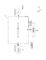
- FIG 2 shows a functional diagram of one of the control units 4, 4' according to figure 1 .
- the cabinet 5 generates and sends a control signal switching the points for moving the point blades in a predetermined position (normal or reverse).
- the oil-hydraulic control unit 4 is operated and it supplies pressurized oil to oil-hydraulic actuating means 1, 2 or 3. Point blades A1 and A2 are moved. When the moving stroke ends once the normal or reverse end position is reached the supplying action is stopped and monitoring signals are generated and sent indicating that point blades have reached the proper position.
- control unit 4 is provided with operator interfaces denoted by 7 by means of which the operator can perform adjustments, monitoring and maintenance operations and in case it is also possible to manually operate means generating and supplying the pressurized oil-hydraulic fluid, such as for example a manual pump and or the like.
- the oil-hydraulic actuators are in the form of two opposed oil-hydraulic linear cylinders or more simply in the form of a double acting cylinder, such as the one denoted by 1 in figure 3 .
- the hydraulic control unit is directly connected to the actuators controlling the movement of the point blades such as shown in figure 3 .
- This figure shows the hydraulic circuit of the control unit.
- An oil-hydraulic double-acting actuator 1 of a switch machine is connected by its inlets to two lines 10, 11 of a hydraulic circuit supplying a oil-hydraulic fluid.
- a pump 12, driven by an electric motor 13 draws by its delivery ends/outlets 14, 15 from an oil-hydraulic fluid reservoir 16.
- the pump is of the reversible type, namely the fact of reversing the rotational direction causes the oil-hydraulic fluid flow direction to be reversed, thus the one that initially was the delivery end becomes the outlet and the one that was the outlet becomes the delivery end.
- the fact of reversing the oil-hydraulic fluid flow in the circuit therefore causes in one case the fluid to be supplied to one of the two chambers separated by the piston 101, thus the latter translates in a first direction.
- the operating direction of the pump is reversed, and therefore the fluid flow direction is reversed, it is supplied to the chamber at the side opposite to the previous one of the piston, therefore the latter moves in the opposite direction. Therefore at the same time the two lines 10 and 11 of the circuit alternately act as the delivery line and as the return line.
- each one of the lines there is advantageously provided a pressure reducing valve for the fluid whether a maximum pressure value 17, 18 is exceeded.
- the direction of the oil-hydraulic fluid flow is reversed by reversing the rotational direction of the driving electric motor 13.
- this is achieved by a combination of switches which are driven contemporaneously with the point blades A1 and A2 reaching the end position and which switch the power supply circuit of the motor such to stop its operation in the rotational direction of the stroke ended and such to supply the motor power signal such that the motor performs a stroke opposite with respect to the previous one when it is again operated.
- monitoring switches are operated causing a control signal to be generated which is detected in the cabinet from where the signal driving the switch machine comes from, that is the power signal operating the pump motor.
- a branch 20, 21 supplying/returning the oil-hydraulic fluid to hydraulic timing means denoted by 23 comes out, which define a length of time based on the change of operating physical parameters of the hydraulic circuit and in particular based on the supplied volume of the pressurized oil-hydraulic fluid.
- flow rate regulators are provided in the two branches. Moroever in the branches 20 and 21 there are provided valves 25 for setting a fluid pressure threshold below which valves remain closed and prevent the fluid from being supplied to the timing cylinder. This minimum pressure for supplying the timing cylinder is set at a value slightly lower than the one set in pressure reducing valves 17, 18 in the delivery/return lines 10, 11 leading to the actuator 1 moving the point blades.
- Advantageously means for measuring the time on the basis of the supplied fluid volume are composed of a double-acting cylinder 23.
- the two branches 20, 21 are connected each one to one of two chambers of the cylinder provided at opposite sides of the piston 123.
- the oil-hydraulic fluid is supplied into one of the two lines 10 or 11 depending on the rotational direction of the driving motor 13 and on the corresponding operating direction of the pump 12. Said fluid is supplied both to the actuator moving the point blades 1 and, once a specific pressure is reached, to the timing cylinder.
- the piston 123 of the timing cylinder moves in one direction or in the opposite one. Since the cylinder volume and that is the length and the diameter are fixed, the stroke of the piston is a constant value too and it always exactly corresponds to the same amount of oil-hydraulic fluid, namely the same volume of said fluid that has to be supplied to the timing cylinder.
- valves 25 By setting the flow rate of the fluid supplied to the timing cylinder 23 by means of flow rate regulators 24 and a predetermined threshold pressure opening the valves 25 it is possible to set the operating modes of the timing cylinder.
- the adjustable valves 25 open when the fluid pressure reaches the predetermined threshold pressure value.
- the timing cylinder is supplied at a pressure greater than or equal to the threshold value set in valves 25 and at a pressure lower than or equal to that set in maximum pressure reducing valves 17 and 18.
- the pressure overcomes the value set in valves 25 and the latter open, the piston makes its stroke between two predetermined positions within a given time which is predetermined and dependent on said settings, therefore it can act as a hydraulic timing member for controlling operations adjusting and monitoring the operating steps of the control unit 4.
- an operating rod 223 is associated to the piston which directly or by means of a transmission drives the control members 26, 27, 28 and 29 of one or more switches which in this case serve for several functions such as particularly for breaking/reversing the power signal to the motor 13 and generating monitoring signals when point blades A1 and A2 reach the end positions.
- 110 and 111 denote a further delivery/return line and a further return/delivery line respectively of the oil-hydraulic fluid circulation circuit, which lines 110, 111 are intended for being connected to a further switching actuator of the points.
- This can be for example an intermediate actuator like those denoted by 2 in figure 1 or an actuator for the points frog like those denoted by 3, 3' in figure 1 .
- the further lines 110 and 111 are provided with pressure reducing valves denoted by 117 and 118 which reduce the pressure of the fluid operating the further actuators to a value different than that provided in lines 10 and 11 connected to the double-acting actuator 101.
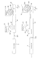
- FIGS 4 and 5 schematically show an example of said control members 28, 29.
- the timing cylinder 23 has a rod 223 directly connected to a slide 30 bearing a cam 29 specifically a trapezoidal one and a rack 28 the two control members cam 29 and rack 28 have not to be necessarily provided on the same slide or in any other arragement where they are not independent each other.
- the control multipolar switch 26 has a spindle 126 by means of which the movement of the contacts is operated in the several switching positions and upon which spindle a gearwheel 226 is fitted engaging the rack 28.
- the movement of the piston causes the rack to be moved and the switching condition of the contacts of the control multipolar switch to be changed.
- the switch 27 comprises control members, such as levers or buttons 127 cooperating with the cam 29 having such a profile that the movement of the slide upon which it is fitted causes the switching condition of said switch 27 to be changed upon the movement of the rod 223 of the timing cylinder 23 by means of which the power supply to the motor 13 is broken and the power signal to the motor is reversed for preparing it to be driven for performing the operation opposite than the previous one.
- control members such as levers or buttons 127 cooperating with the cam 29 having such a profile that the movement of the slide upon which it is fitted causes the switching condition of said switch 27 to be changed upon the movement of the rod 223 of the timing cylinder 23 by means of which the power supply to the motor 13 is broken and the power signal to the motor is reversed for preparing it to be driven for performing the operation opposite than the previous one.
- Figures 4 and 5 show the timing cylinder 23 and the rod 223 as well as the slide with control members 28 and 29 of the switches 26 and 27 in the normal and reverse condition of the points respectively, that is with the piston 123 of the timing cylinder 23 in the corresponding end positions inside the cylinder.
- switches 26 27 and so how the functions determined by the several switching conditions thereof are controlled within time periods defined by the timing cylinder 23 and how such time periods depend on and are adjustable for example by acting on the flow rate regulating means 24 in branches 20 and 21 supplying the timing cylinder.
- control members 28, 29 can be connected to the rod 223 of the timing cylinder 23 by means of a transmission, which transmission can be of the type changing with respect to the rate according to predetermined ratios or in a continuous way, such to modify the length of the time periods necessary for taking the switches 26 and 27 from a switching condition to a second switching condition.
- Such adjustments can be useful for example for allowing the operating conditions to be optimized under several weather extreme conditions that therefore drastically modify the characteristics of the oil-hydraulic fluid, or for maintenance adjustments.
- control unit The construction of the control unit described above allows a switch machine to be supplied and operated according to the modes described below:
- Contacts of the switch 26 advantageously are of the "sliding" type integral with the position of the mechanical members moving with the slide and the cam 29, such contacts, being engaged in suitable seats, make the circuit configuration associated to the fact of reaching the End of Operation condition for a Normal/Reverse position.
- the switch 26 being operated by the timing cylinder 23 causes the monitoring circuit to be closed/opened consistently with the operation set by the Cabinet, such consistency is guaranteed by mechanical members transmitting the motion from the timing Cylinder to the switch.
- Delivery and return lines of the oil-hydraulic circuit are at the same pressure.
- Control contacts are configured for the Normal position.
- the timing cylinder is not operating and the control members of monitoring and operating switches are in position.
- the counter indicates the number of operations performed.
- the Cabinet supplies power.
- the oil-hydraulic control unit starts to pressurize the oil in the delivery line.
- Monitoring contacts are configured for the Normal position.
- the timing cylinder is not operating and the control members of monitoring and operating switches are in position.
- the counter indicates the number of operations performed.
- the Cabinet supplies power.
- the control unit provides to flow oil-hydraulic fluid.
- the control unit supplies oil-hydraulic fluid to the actuator moving the point blades.
- the piston and the rod of the timing cylinder begin to translate.
- Control members of the monitoring and operating switches are operated.
- the counter indicates the number of operations performed.
- the control unit supplies oil-hudraulic fluid to the actuator moving the point blades.
- the oil flows from the delivery line directly to the return line due to the pressure relief by the pressure reducing valve in delivery/return lines 10, 11.
- Monitoring contacts are configured for the Normal position.
- the piston and the rod of the cylinder continue to translate.
- Control members of the monitoring and operating switches are operated.
- the counter indicates the number of operations performed.
- the control unit does not supply oil-hydraulic fluid to the actuator moving the point blades.
- Monitoring contacts are configured for the Reverse position (event preceding the operating Contacts being switched).
- Control members of the monitoring switches and of the operating switches take the corresponding position.
- the counter adds 1 to the number of operations performed.
- the Cabinet does not supply power.
- the delivery and return lines of the oil-hydraulic circuit are at the same pressure.
- Monitoring contacts are configured for the Reverse position.
- the timing cylinder is not operating.
- the control members of the monitoring switches and of the operating switches take the corresponding position.
- the counter adds 1 to the number of operations performed.
- the Cabinet provides power supply.
- the oil-hydraulic control unit starts to pressurize the oil in the delivery line.
- Monitoring contacts are configured for the Reverse position.
- the timing cylinder is not operating.
- the control members of the monitoring switches and of the operating switches take the corresponding position.
- the counter indicates the number of operations performed.
- the Cabinet supplies power.
- the control unit provides the oil-hydraulic fluid to be circulated.
- the control unit supplies oil-hudraulic fluid to the actuator moving the point blades.
- Monitoring contacts are configured for the Reverse position.
- the piston and the rod of the timing cylinder begin to translate.
- Control members of the monitoring and operating switches are operated.
- the counter indicates the number of operations performed.
- the Cabinet supplies power.
- the control unit supplies oil-hydraulic fluid to the actuator moving the point blades.
- the oil flows from the delivery line directly to the return line due to the pressure relief by the pressure reducing valve in delivery/return lines 10, 11.
- Monitoring contacts are configured for the Reverse position.
- the piston and the rod of the cylinder continue to translate.
- Control members of the monitoring and operating switches are operated.
- the counter indicates the number of operations performed.
- the Cabinet does not supply power.
- the control unit does not supply oil-hydraulic fluid to the actuator moving the point blades.
- Monitoring contacts are configured for the Normal position (event preceding the operating Contacts being switched).
- the timing cylinder is not operating.
- Control members of the monitoring switches and of the operating switches take the corresponding position.
- the counter indicates the number of operations performed + 2.
- control unit In case of incomplete movement the control unit is in the condition with the timing Cylinder in the intermediate position and the monitoring contacts are not switched and the operating contacts are still arranged for the started but not completed operation. In this condition the operation has to be again started such to allow the control unit to reach the End of Operation condition. If the fact of starting again the operation does not allow the electrical control on the control unit to be acquired this is a situation where the control unit or external Interfaces could have been subjected to failures.
- the incomplete movement can be detected in case of external events acting on the interface to the Cabinet, the non-transmission of electrical (operating or monitoring) signals causes the overall railway points system not to acquire the control.
- the incomplete movement can be detected in case of external events, such as the provision of obstacles or obstructions, which causes the pressure operating the pressure limiting devices to be reached earlier than expected causing the control unit to make its operation, in such case the overall railway points system does not acquire the electrical control.
- external events such as the provision of obstacles or obstructions, which causes the pressure operating the pressure limiting devices to be reached earlier than expected causing the control unit to make its operation
- the overall railway points system does not acquire the electrical control.
- leakages due to ruptures or similar failures it is possible for the control unit not to be able to reach the End of Operation condition and therefore the event is detected due to the non-acquisition of the electrical control by the control unit and by the overall railway points system.
- the timeout provided by the Cabinet can act by breaking the power supply before acquiring the electrical control therefore the event is detected due to the non-acquisition of the electrical control. In this case the fact of starting again the operation can allow the control unit to achieve its Mission but the failure, if any, is detected by the direct inspection.
Landscapes
- Engineering & Computer Science (AREA)
- Mechanical Engineering (AREA)
- Fluid-Pressure Circuits (AREA)
Abstract
electrical means for functionally monitoring the movement of the point blades and/or that the end position the point blades have been moved to has been reached;
timing means for stopping the actuating stroke of actuators moving the point blades when one of the end positions has been reached and/or after a predetermined operating time of said actuators moving the point blades and
means for switching the direction of the actuating stroke, by reversing the circulation direction of the oil-hydraulic fluid to the actuator translating point blades for operating it in the opposite direction,
the pump is of the reversible type like also the driving motor, the electrical means switching the movement stroke direction of the point blades being composed of switches reversing the power supply signal of an electric motor driving the pump for reversing the rotational direction of said motor and of said pump and which are driven when the point blades reach the proper end position such to generate said reversal of the circulation direction of the oil-hydraulic fluid flow in the circulation circuit.
Description
- The invention relates to an oil-hydraulic control unit for supplying oil-hydraulic actuators in switch machines of railway points or the like, which control unit comprises a closed circulation circuit of an oil-hydraulic fluid, wherein at least a circulation pump with a delivery end and an intake end connected to a delivery line and a return line respectively of the circulation circuit of said fluid is provided and which delivery and return lines of the circulation circuit are connected to at least an oil-hydraulic actuator translating the point blades of the points respectively, for moving said point blades from one position to the other one of two end positions one of such positions being called normal position while the other one of said two positions is called reverse position, there being provided
electrical means for functionally monitoring the movement of the point blades and/or that the end position the point blades have been moved to has been reached;
timing means for stopping the actuating stroke of actuators moving the point blades when one of the end positions has been reached and/or after a predetermined operating time of said actuators moving the point blades and
means for switching the direction of the actuating stroke, by reversing the circulation direction of the oil-hydraulic fluid to the actuator translating point blades for operating it in the opposite direction. - This type of control units are known and widely used. The operation moving the point blades of a points causes one of the two point blades to be alternately moved in a position approaching the rail provided at the same longitudinal side of the railway line of the corresponding point blade, while the opposite point blade is moved in a position away from the corresponding rail. Operations, such as also the positions of the point blades resulting therefrom, are conventionally called as normal and reverse, since the points acts for deviating the train route from a specific path.
- Oil-hydraulic actuators have been used in the last years for moving the point blades.
- A double-acting linear actuator or two linear actuators which are independent and operate oppositely each other are connected to the delivery lines of an oil-hydraulic circuit. The oil-hydraulic fluid is supplied to the actuators by an electric motor driven pump which takes the fluid from a reservoir or which causes the fluid to flow in a closed circuit with a delivery line and a return line.
- In order to achieve the movement from the normal position to the reverse position and the opposite one from the reverse position to the normal position in the supply circuit there are provided valves which are electrically operated and can be switched such to connect the delivery end of the circulation pump, that is the delivery line of the circuit in a first condition to the inlet of one of the two actuators or to one of the two inlets of a double-acting actuator and in a second condition to the inlet of the other one of the two actuators or to the other inlet of a double-acting actuator. Contemporaneously the actuator not supplied by the fluid or the inlet of the double-acting cylinder not connected to the delivery line is connected to the intake end of the circulation pump by the return line of the circulation circuit.
- An oil-hydraulic fluid reservoir acts for drawing said fluid and filling the closed circuit or for gathering the oil-hydraulic fluid discharged from one or more outlets of said circuit.
- The length of time the fluid is supplied to the actuators is determined by electrical means such as pressure sensors and/or electric timers or valves or combinations of such means.
- In addition to the fact that the construction of the control unit is made more complex and expensive, known solutions providing electrical means for switching the movement direction of the point blades and timing electrical means are relatively not much safe as regards the functional point of view with reference to the high standards required in the railway field and in similar fields.
- The invention aims at improving a control unit of the type described hereinbefore such to make said control unit less complex and less expensive from a constructional point of view and more strong and reliable as regards the functional point of view.
- According to a first aspect the invention achieves the above aims by providing a control unit of the type described hereinbefore and that is an oil-hydraulic control unit for supplying oil-hydraulic actuators in switch machines of railway points or the like, which control unit comprises a closed circulation circuit for an oil-hydraulic fluid, wherein at least a circulation pump is provided with a delivery end and an intake end connected to a delivery line and a return line respectively of the circulation circuit of said fluid and which delivery and return lines of the circulation circuit are connected to at least an oil-hydraulic actuator respectively translating the point blades of the points, for moving said point blades from one position to the other one position of two end positions one of such positions being called normal position while the other one of said two positions is called reverse position, there being provided
electrical means for functionally monitoring the movement of the point blades and/or that the end position the point blades have been moved to has been reached;
timing means for stopping the actuating stroke of actuators moving the point blades when one of the end positions has been reached and/or after a predetermined operating time of said actuators moving the point blades and
means for switching the direction of the actuating stroke, by reversing the circulation direction of the oil-hydraulic fluid to the actuator translating point blades for operating it in the opposite direction,
which control unit further showing the characteristic that the pump is of the reversible type like also the driving motor, the electrical means switching the movement stroke direction of the point blades being composed of switches reversing the power supply signal of an electric motor driving the pump for reversing the rotational direction of said motor and of said pump and which are driven when the point blades reach the proper end position such to generate said reversal of the circulation direction of the oil-hydraulic fluid flow in the circulation circuit. - By this arrangement it is not more necessary to provide combinations of electrically controlled valves by means of which the connection of the pump delivery end is reversed first from an actuating cylinder then to the other one or first to one and then to the other one of the two inlets of a double-acting actuator.
- The reversible pump can reverse the supply flow of the oil-hydraulic fluid and therefore the movement direction of the point blades, by simply changing the driving direction thereof and that is the rotational direction for example of a driving electric motor.
- Apart from the provision of simple electrical switches which simply reverse the polarity of the power supply signal of the electric motor, no control electronics is necessary such as that currently necessary for operating the valve switching. Morevoer switching controls for said valves are omitted which would be necessary anyway.
- According to a further aspect that can be provided instead of or in combination with the one described above, the invention provides an oil-hydraulic control unit for supplying oil-hydraulic actuators in switch machines of railway points or the like, which control unit comprises a closed circulation circuit for an oil-hydraulic fluid, wherein at least one circulation pump is provided with a delivery end and an intake end connected to a delivery line and a return line respectively of the circulation circuit of said fluid and which delivery and return lines of the circulation circuit are connected to at least an oil-hydraulic actuator translating the point blades of the points respectively, for moving said point blades from a position to the other one of two end positions one of which positions being called normal position while the other one of said two positions is called reverse position, there being provided
electrical means for functionally monitoring the movement of the point blades and/or that the end position the point blades have been moved to has been reached;
timing means for stopping the actuating stroke of actuators moving the point blades when one of the end positions has been reached and/or after a predetermined operating time of said actuators moving the point blades and
means for switching the direction of the actuating stroke, by reversing the circulation direction of the oil-hydraulic fluid to the actuator translating point blades for operating it in the opposite direction,
wherein timing means are hydraulic means detecting changes in flow parameters in the hydraulic circulation circuit and on the basis thereof they operate at least electrical switches breaking the power supply of a motor driving the pump and in case said electrical means switching the movement stroke direction of the point blades and/or the means functionally monitoring the movement of the point blades and the fact they have reached the proper end position. - In addition to the above advantages with respect to the prior art, the use of a hydraulic timer allows the failure mean time (MTBF = mean Time Before Failure) of the timer unit of the control unit to be increased.
- At the same time in case of low temperatures the hydraulic timer acts has a kind of closed loop feedback. By means of this it is possible to increase the overall time during which the pressure of the oil-hydraulic fluid necessary to completely carry out the operation is available, reducing risks related to possible wrong or not complete operations.
- According to the present invention, therefore timing means are hydraulic means detecting changes in flow parameters in the hydraulic circuit and on the basis of said changes they control the electrical switches breaking the power supply of a motor driving the pump and in case said electrical means switching the movement stroke direction of point blades as well as means functionally monitoring the movement of the point blades and the fact they have reached the proper end position.
- In one embodiment, said timing means control the breaking of the power supply to the electric motor of the pump and the circuit monitoring the position of the point blades on the basis of the amount of oil-hydraulic fluid supplied by the pump to a timing cylinder/piston assembly.
- According to an improvement the oil-hydraulic fluid is supplied to the timing cylinder/piston assembly through a valve allowing the fluid passage when it reaches a certain pressure.
- In one example the timing cylinder/piston assembly is connected by branches to at least the delivery line of the oil-hydraulic circulation circuit for supplying the linear actuator moving the point blades, said timing cylinder/piston assembly being connected to mechanical means controlling electrical switches constituting the electrical means for functionally monitoring the movement of the point blades and/or the fact they have reached the end position, as well as to electrical means for switching the movement direction of point blades and to electrical means breaking the power supply circuit of the motor of the pump.
- Advantageously the timing cylinder is of the double-acting type, one of the delivery and return lines of the oil-hydraulic circulation circuit supplying the linear actuator moving the point blades being connected thereto respectively, that is one of the intake/delivery ports of the pump.
- In this case, each inlet/outlet of the timing cylinder/piston assembly is connected to the corresponding delivery and return line of the circulation circuit supplying the oil-hydraulic fluid by means of an automatic valve with a shutter movable in the opened condition by the oil-hydraulic fluid pressure.
- According to a characteristic of the invention the timing cylinder/piston assembly is mechanically connected, directly or by a transmission, to a mechanical control member switching the electrical contacts.
- At least a part of the electrical contacts is provided in circuits generating signals monitoring the functional condition and the fact that point blades have properly reached the end position and at least a part of the electrical contacts is a part of a circuit supplying/reversing the power supply signal of the motor.
- In order to match or adjust the length of the interval of time of the operation of actuators moving the point blades with reference to specific requirements, inside the control unit according to the invention there can be provided means for changing the intervals of time of the operation of actuators moving the point blades.
- One embodiment provides the timing cylinder/piston assembly to be mechanically connected by a transmission to a mechanical control member switching the electrical contacts, said transmission being adjustable as regards the ratio of the inlet stroke to the outlet stroke of said transmission.
- A variant embodiment that can be provided in combination with the previous embodiment provides the control unit to comprise flow rate regulators in the branches connecting the delivery and return lines of the oil-hydraulic circulation circuit supplying the actuator moving the point blades to the timing cylinder/piston assembly, which regulators are of the variable type as regards the flow rate.
- Moreover in order to keep the actuators and the circuit safe from mulfunctions that can cause the pressure of the oil-hydraulic fluid to increase in a potentially harmful way, the control unit can also comprise automatic pressure relief valves for the oil-hydraulic fluid when said oil-hydraulic fluid reaches a predetermined maximum pressure.
- According to an improvement that can be provided in combination with one or more of the above characteristics the oil-hydraulic fluid circulation circuit provides at least a further delivery line and at least a corresponding further return line for controlling a further switching actuator.
- Such actuator can be an intermediate switching actuator like those denoted by 2 in
figure 1 or a frog switching actuator like those denoted by 3, 3' infigure 1 . - Likewise what mentioned above the actuator can be of the double-acting type or can be composed of a pair of linear actuators working oppositely each other.
- Still according to a further characteristic, by means of pressure limiting devices it is possible to provide a different pressure of the circulation fluid in each further pair of delivery and return lines, which pressure is intended for controlling the actuator connected thereto with respect to the pressure of the first pair of delivery and return lines.
- Such characteristic can be provided individually from previous ones and therefore the invention provides an oil-hydraulic control unit for supplying oil-hydraulic actuators in switch machines of railway points or the like, which control unit comprises a closed circulation circuit for an oil-hydraulic fluid, wherein at least one circulation pump is provided with a delivery end and an intake end connected to a delivery line and a return line respectively of the circulation circuit of said fluid and which delivery and return lines of the circulation circuit are connected to at least an oil-hydraulic actuator translating the point blades of the points respectively, for moving said point blades from a position to the other one of two end positions one of which positions being called normal position while the other one of said two positions is called reverse position, there being provided
at least a further delivery line and at least a corresponding further return line for controlling a further switching actuator. - These characteristics can be provided in combination with any further characteristics listed above and especially with
electrical means for functionally monitoring the movement of the point blades and/or that the end position the point blades have been moved to has been reached;
timing means for stopping the actuating stroke of actuators moving the point blades when one of the end positions has been reached and/or after a predetermined operating time of said actuators moving the point blades and
means for switching the direction of the actuating stroke, by reversing the circulation direction of the oil-hydraulic fluid to the actuator translating point blades for operating it in the opposite direction. - The invention relates to a method for controlling an oil-hydraulic system moving point blades in a railway points or the like for carrying out the operation moving said point blades between one of two positions one of which positions being called normal while the other one of said two positions is called reverse position, which method provides
- Setting a predetermined interval of time for moving point blades from one to the other one of said two normal and reverse positions;
operating oil-hydraulic means moving the point blades by supplying a pressurized oil-hydraulic fluid for carrying out said operation moving the point blades from the normal position to the reverse one or vice versa;
measuring the interval of time during which the pressurized oil-hydraulic fluid is supplied for carrying out said operation;
at least stopping the pressurized oil-hydraulic fluid from being supplied when the length of time of the measured interval of time is equal to that of the predetermined interval of time which has been set;
and at least preparing the oil-hydraulic fluid supplying circuit to reverse the direction of the oil-hydraulic fluid flow for operating oil-hydraulic means moving the point blades in the reverse direction, to carry out the reverse operation moving the point blades with respect to the previously carried out operation;
and wherein the interval of time during which the pressurized oil-hydraulic fluid is supplied for carrying out said operation is hydraulically measured by detecting the volume of the oil-hydraulic fluid supplied by the pump. - Advantageosuly the volume of the fluid moved in the supply circuit is detected by a unit transforming the change in the oil-hydraulic fluid volume into a mechanical motion controlling switching means/switches stopping and/or reversing the supply of the pressurized oil-hydraulic fluid flow.
- As regards the charging of the closed circuit according to one or more of the previous combinations and embodiments and as regards the storage of the fluid possibly discharged from said closed circuit when maximum pressures provided by relief valves are exceeded, there is provided a oil-hydraulic fluid reservoir which serve for taking said fluid and charging the closed circuit or for storing the oil-hydraulic fluid discharged from one or more ports of said circuit.
- Further improvements of the invention are the object of the subclaims.
- Characteristics of the invention and advantages deriving therefrom will be clear from the following description of one embodiment shown in annexed drawings, wherein:
-
Fig.1 is an example of railway points comprising a plurality of switch machines each one provided with actuators for moving the point blades and said switch machines being lenghtwise arranged throughout the point blades and in the frog area and which actuators are of the oil-hydraulic type and are supplied by hydraulic control units. -
Fig.2 is a functional block diagram of a hydraulic control unit supplying the oil-hydraulic actuators of railway points. -
Fig.3 is a circuit diagram of a control unit according tofigure 2 . -
Fig. 4 and fig.5 schematically show one of two positions of the piston of a timing cylinder and of the control rack switching the contacts stopping and reversing the polarity of the power supply of the electric motor driving a pump of the hydraulic control unit as well as contacts monitoring that point blades have reached the proper switching end position. - The invention relates to a hydraulic control unit for supplying switch machines of point blades of railway points or the like. The switch machine is provided with oil-hydraulic actuating means controlling the movement of the point blades and receiving the pressurized oil from the hydraulic control unit.
-
Figure 1 shows a particular example of such points. The points shown is of the type used for high speed lines, where the point blades have a considerable length and where the movement of the point blades is controlled by several switch machines, that is by several actuators arranged throughout the length of the point blades and in the frog area thereof. - Obviously the invention is not limited to switch machines for this type of points, but it can be applied also to conventional points where a single switch machine is provided, that is one actuator in only one position with respect to point blades and namely generally at the end portions thereof.
- A1 and A2 denote the point blades of the points.
Referral numbers - The command for performing the operation moving the point blades is sent from a control cabinet and upon the reception thereof the
control unit 4, 4' begins to supply the actuators for performing the moving stroke of the point blades A1, A2. - Point blades A1 and A2 can be moved together one with respect to the other between two extreme positions,
figure 1 showing the so called normal position, where the point blade A2 is in contact with the rail directly adjacent to said point blade A2, while the point blade A1 is spaced apart from the rail adjacent thereto. The train keeps a straight travel. - On the contrary in the so called reverse position the point blade A1 is in a position adhering to the associated rail and the point blade A2 is spaced apart from the rail adjacent thereto. In this case a train would be diverged from the straight direction into the branch towards the bottom of the sheet.
- As it is generally provided for prior art points, switch machines are provided with sensors by means of which it is possible to verify that point blades have reached the proper normal or reverse position at the end of each operation moving the point blades. In this case these are monitoring contacts closing monitoring circuits by means of which monitoring signals are generated which are transmitted or read by cabinets which send commands for performing points operations.
-
Figure 2 shows a functional diagram of one of thecontrol units 4, 4' according tofigure 1 . The cabinet 5 generates and sends a control signal switching the points for moving the point blades in a predetermined position (normal or reverse). - The oil-
hydraulic control unit 4 is operated and it supplies pressurized oil to oil-hydraulic actuating means 1, 2 or 3. Point blades A1 and A2 are moved. When the moving stroke ends once the normal or reverse end position is reached the supplying action is stopped and monitoring signals are generated and sent indicating that point blades have reached the proper position. - Moreover the
control unit 4 is provided with operator interfaces denoted by 7 by means of which the operator can perform adjustments, monitoring and maintenance operations and in case it is also possible to manually operate means generating and supplying the pressurized oil-hydraulic fluid, such as for example a manual pump and or the like. - In order to allow the point blades to alternately move from one to the other one of the two normal and reverse positions of the points, the oil-hydraulic actuators are in the form of two opposed oil-hydraulic linear cylinders or more simply in the form of a double acting cylinder, such as the one denoted by 1 in
figure 3 . - The general construction of the points in the several switch machines according to prior art is described in more details in
EP712772 - Unlike several known solutions providing the oil-hydraulic fluid to be supplied to a distribution reservoir wherein said oil-hydraulic fluid is stored at the operating pressure, the hydraulic control unit according to the present invention is directly connected to the actuators controlling the movement of the point blades such as shown in
figure 3 . - This figure shows the hydraulic circuit of the control unit.
- An oil-hydraulic double-acting
actuator 1 of a switch machine is connected by its inlets to two lines 10, 11 of a hydraulic circuit supplying a oil-hydraulic fluid. Apump 12, driven by an electric motor 13 draws by its delivery ends/outlets 14, 15 from an oil-hydraulic fluid reservoir 16. - The pump is of the reversible type, namely the fact of reversing the rotational direction causes the oil-hydraulic fluid flow direction to be reversed, thus the one that initially was the delivery end becomes the outlet and the one that was the outlet becomes the delivery end. The fact of reversing the oil-hydraulic fluid flow in the circuit therefore causes in one case the fluid to be supplied to one of the two chambers separated by the
piston 101, thus the latter translates in a first direction. When the operating direction of the pump is reversed, and therefore the fluid flow direction is reversed, it is supplied to the chamber at the side opposite to the previous one of the piston, therefore the latter moves in the opposite direction. Therefore at the same time the two lines 10 and 11 of the circuit alternately act as the delivery line and as the return line. - In the oil-hydraulic fluid supply circuit, in each one of the lines there is advantageously provided a pressure reducing valve for the fluid whether a
maximum pressure value 17, 18 is exceeded. - The direction of the oil-hydraulic fluid flow is reversed by reversing the rotational direction of the driving electric motor 13. As it will be noted below in more details, this is achieved by a combination of switches which are driven contemporaneously with the point blades A1 and A2 reaching the end position and which switch the power supply circuit of the motor such to stop its operation in the rotational direction of the stroke ended and such to supply the motor power signal such that the motor performs a stroke opposite with respect to the previous one when it is again operated. Contemporanously with such action when the end position of the point blades A1 and A2 is reached, monitoring switches are operated causing a control signal to be generated which is detected in the cabinet from where the signal driving the switch machine comes from, that is the power signal operating the pump motor.
- From each one of the two lines 10 and 11, of the circuit supplying the oil-hydraulic fluid to the
actuator 1 moving the point blades, abranch 20, 21 supplying/returning the oil-hydraulic fluid to hydraulic timing means denoted by 23 comes out, which define a length of time based on the change of operating physical parameters of the hydraulic circuit and in particular based on the supplied volume of the pressurized oil-hydraulic fluid. - In order to properly set the time measurement on the basis of the change in the oil-hydraulic fluid volume, that is the volume of the fluid supplied during the operating step of the
pump 12, flow rate regulators are provided in the two branches. Moroever in thebranches 20 and 21 there are providedvalves 25 for setting a fluid pressure threshold below which valves remain closed and prevent the fluid from being supplied to the timing cylinder. This minimum pressure for supplying the timing cylinder is set at a value slightly lower than the one set inpressure reducing valves 17, 18 in the delivery/return lines 10, 11 leading to theactuator 1 moving the point blades. - Advantageously means for measuring the time on the basis of the supplied fluid volume are composed of a double-acting
cylinder 23. The twobranches 20, 21 are connected each one to one of two chambers of the cylinder provided at opposite sides of the piston 123. - When the pump is driven the oil-hydraulic fluid is supplied into one of the two lines 10 or 11 depending on the rotational direction of the driving motor 13 and on the corresponding operating direction of the
pump 12. Said fluid is supplied both to the actuator moving thepoint blades 1 and, once a specific pressure is reached, to the timing cylinder. - Similarly to the actuator moving the point blades, depending on the operating direction of the
pump 12, the piston 123 of the timing cylinder moves in one direction or in the opposite one. Since the cylinder volume and that is the length and the diameter are fixed, the stroke of the piston is a constant value too and it always exactly corresponds to the same amount of oil-hydraulic fluid, namely the same volume of said fluid that has to be supplied to the timing cylinder. - By setting the flow rate of the fluid supplied to the
timing cylinder 23 by means offlow rate regulators 24 and a predetermined threshold pressure opening thevalves 25 it is possible to set the operating modes of the timing cylinder. Theadjustable valves 25 open when the fluid pressure reaches the predetermined threshold pressure value. The timing cylinder is supplied at a pressure greater than or equal to the threshold value set invalves 25 and at a pressure lower than or equal to that set in maximumpressure reducing valves 17 and 18. When the pressure overcomes the value set invalves 25 and the latter open, the piston makes its stroke between two predetermined positions within a given time which is predetermined and dependent on said settings, therefore it can act as a hydraulic timing member for controlling operations adjusting and monitoring the operating steps of thecontrol unit 4. In addition advantageously if the pressure drops under the value set invalves 25, the latter close and the movement of the piston and so the timing are stopped. When the pressure exceeds again the value set invalves 25, they open again and the piston recovers its stroke and so also the timing function is recovered. - With the timing cylinder as a double-acting one, an operating
rod 223 is associated to the piston which directly or by means of a transmission drives thecontrol members - Again with reference to
figure 3 , 110 and 111 denote a further delivery/return line and a further return/delivery line respectively of the oil-hydraulic fluid circulation circuit, which lines 110, 111 are intended for being connected to a further switching actuator of the points. This can be for example an intermediate actuator like those denoted by 2 infigure 1 or an actuator for the points frog like those denoted by 3, 3' infigure 1 . - Still according to a further characteristic, the further lines 110 and 111 are provided with pressure reducing valves denoted by 117 and 118 which reduce the pressure of the fluid operating the further actuators to a value different than that provided in lines 10 and 11 connected to the double-acting
actuator 101. -
Figures 4 and 5 schematically show an example of saidcontrol members - The construction is schematically shown since the specific construction is within the range of the average person skilled in the art and particularly for
control members 28 and for the controlmultipolar switch 26 described inEP712772 - In the schematic arrangement of
figures 4 and 5 , thetiming cylinder 23 has arod 223 directly connected to aslide 30 bearing acam 29 specifically a trapezoidal one and arack 28 the twocontrol members cam 29 andrack 28 have not to be necessarily provided on the same slide or in any other arragement where they are not independent each other. - The control
multipolar switch 26 has aspindle 126 by means of which the movement of the contacts is operated in the several switching positions and upon which spindle agearwheel 226 is fitted engaging therack 28. The movement of the piston causes the rack to be moved and the switching condition of the contacts of the control multipolar switch to be changed. - The
switch 27 comprises control members, such as levers orbuttons 127 cooperating with thecam 29 having such a profile that the movement of the slide upon which it is fitted causes the switching condition of saidswitch 27 to be changed upon the movement of therod 223 of thetiming cylinder 23 by means of which the power supply to the motor 13 is broken and the power signal to the motor is reversed for preparing it to be driven for performing the operation opposite than the previous one. -
Figures 4 and 5 show thetiming cylinder 23 and therod 223 as well as the slide withcontrol members switches timing cylinder 23 in the corresponding end positions inside the cylinder. - It has to be noted how switches 26 27 and so how the functions determined by the several switching conditions thereof are controlled within time periods defined by the
timing cylinder 23 and how such time periods depend on and are adjustable for example by acting on the flow rate regulating means 24 inbranches 20 and 21 supplying the timing cylinder. - According to a not shown embodiment,
control members rod 223 of thetiming cylinder 23 by means of a transmission, which transmission can be of the type changing with respect to the rate according to predetermined ratios or in a continuous way, such to modify the length of the time periods necessary for taking theswitches - It is also important to note that it is possible to provide several independent transmissions for the
control members 28 of theswitch 26 and for thecontrol members 29 of theswitch 27. - It has also to be noted that the mechanical solution described here in order to modify the length of the interval of time with respect to the fixed interval of the timing cylinder, can be provided also in combination with the hydraulic solution providing the flow rate in the
branches 20 and 21 to be changed by means of fluid flow rate regulating means 24. - Such adjustments can be useful for example for allowing the operating conditions to be optimized under several weather extreme conditions that therefore drastically modify the characteristics of the oil-hydraulic fluid, or for maintenance adjustments.
- The construction of the control unit described above allows a switch machine to be supplied and operated according to the modes described below:
- Under normal operating conditions the sequence of events that can occur is:
- Power is supplied by the Cabinet 5
- Point blades A1 and A2 are moved
- the electric control is acquired by means of the
timing cylinder 23 thecontrol members 28 and the controlmultipolar switch 26; - the electrical circuit supplying and switching the power supply of the electric motor is broken for operating the bidirectional pump (as regards the flowing direction of the oil-hydraulic fluid) in the direction opposite to the previous one when the motor is again operated. This occurs by means of the
timing cylinder 23 and of theswitch 27 and of thecontrol members 29 thereof. - Contacts of the
switch 26 advantageously are of the "sliding" type integral with the position of the mechanical members moving with the slide and thecam 29, such contacts, being engaged in suitable seats, make the circuit configuration associated to the fact of reaching the End of Operation condition for a Normal/Reverse position. Theswitch 26 being operated by thetiming cylinder 23 causes the monitoring circuit to be closed/opened consistently with the operation set by the Cabinet, such consistency is guaranteed by mechanical members transmitting the motion from the timing Cylinder to the switch. - After switching the contacts of the
monitoring switch 26 the contacts of the operatingswitch 27 are operated. Such sequence guarantees the operation to be completed, if the motor power supply is broken before acquiring the control, the operation could not be completed due to lack of power. - According to a preferred operating mode, operating steps occurring after a command from the Cabinet and after the control unit being consequently operated are described below considering the Normal positioning condition of point blades A1 and A2 and of the actuator to which the control unit is connected as the beginning of the operation.
- Point blades in Normal position.
- Cabinet: does not supply power.
- Delivery and return lines of the oil-hydraulic circuit are at the same pressure.
- Control contacts are configured for the Normal position.
- Operating contacts by means of which the motor is operated such to move the point blades in the Normal position break the Motor power supply circuit, while operating contacts by means of which the motor is power supplied in the driving direction for the movement operation from the normal condition to the reverse condition allow the motor to be power supplied.
- The timing cylinder is not operating and the control members of monitoring and operating switches are in position.
- The counter indicates the number of operations performed.
- Operating command from Normal to Reverse
- The Cabinet supplies power.
- The oil-hydraulic control unit starts to pressurize the oil in the delivery line.
- Monitoring contacts are configured for the Normal position.
- Operating contacts by means of which the motor is operated such to move the point blades in the Normal position break the Motor power supply circuit, while operating contacts by means of which the motor is power supplied in the driving direction for the movement operation from the normal condition to the reverse condition allow the motor to be power supplied.
- The timing cylinder is not operating and the control members of monitoring and operating switches are in position.
- The counter indicates the number of operations performed.
- Operating command from Normal to Reverse, adjustment pressure of the Sequence.
- The Cabinet: supplies power.
- The control unit provides to flow oil-hydraulic fluid.
- The control unit supplies oil-hydraulic fluid to the actuator moving the point blades.
- Monitoring contacts are configured for the Normal position
- Operating contacts by means of which the motor is operated such to move the point blades in the Normal position break the Motor power supply circuit, while operating contacts by means of which the motor is power supplied in the driving direction for the movement operation from the normal condition to the reverse condition allow the motor to be power supplied.
- The piston and the rod of the timing cylinder begin to translate.
- Control members of the monitoring and operating switches are operated.
- The counter indicates the number of operations performed.
- Operating command from Normal to Reverse, adjustment pressure.
- Cabinet: supplies power
- The control unit supplies oil-hudraulic fluid to the actuator moving the point blades.
- In the oil-hydraulic control unit the oil flows from the delivery line directly to the return line due to the pressure relief by the pressure reducing valve in delivery/return lines 10, 11.
- Monitoring contacts are configured for the Normal position.
- Operating contacts by means of which the motor is operated such to move the point blades in the Normal position break the Motor power supply circuit, while operating contacts by means of which the motor is power supplied in the driving direction for the movement operation from the normal condition to the reverse condition allow the motor to be power supplied.
- The piston and the rod of the cylinder continue to translate.
- Control members of the monitoring and operating switches are operated.
- The counter indicates the number of operations performed.
- Reverse position is reached.
- Cabinet: no power is supplied.
- The control unit does not supply oil-hydraulic fluid to the actuator moving the point blades.
- Monitoring contacts are configured for the Reverse position (event preceding the operating Contacts being switched).
- Operating contacts by means of which the motor has been operated such to move the point blades in the Reverse position break the Motor power supply circuit, while operating contacts by means of which the motor is power supplied in the driving direction for the movement operation from the reverse condition to the normal condition allow the motor to be power supplied (event following the control Contacts being switched).
- The translation of the piston and of the rod of the timing Cylinder is stopped.
- Control members of the monitoring switches and of the operating switches take the corresponding position.
- The counter adds 1 to the number of operations performed.
- Points in the reverse position
- The Cabinet does not supply power.
- The delivery and return lines of the oil-hydraulic circuit are at the same pressure.
- Monitoring contacts are configured for the Reverse position.
- Operating contacts by means of which the motor has been operated such to move the point blades in the Reverse position break the Motor power supply circuit, while operating contacts by means of which the motor is power supplied in the driving direction for the movement operation from the reverse condition to the normal condition allow the motor to be power supplied.
- The timing cylinder is not operating.
- The control members of the monitoring switches and of the operating switches take the corresponding position.
- The counter adds 1 to the number of operations performed.
- Operating command from Reverse to Normal
- The Cabinet: provides power supply.
- The oil-hydraulic control unit starts to pressurize the oil in the delivery line.
- Monitoring contacts are configured for the Reverse position.
- Operating contacts by means of which the motor has been operated such to move the point blades in the Reverse position break the Motor power supply circuit, while operating contacts by means of which the motor is power supplied in the driving direction for the movement operation from the reverse condition to the normal condition allow the motor to be power supplied.
- The timing cylinder is not operating.
- The control members of the monitoring switches and of the operating switches take the corresponding position.
- The counter indicates the number of operations performed.
- Operating command from Reverse to Normal, adjusting pressure of the Sequence.
- The Cabinet supplies power.
- The control unit provides the oil-hydraulic fluid to be circulated.
- The control unit supplies oil-hudraulic fluid to the actuator moving the point blades.
- Monitoring contacts are configured for the Reverse position.
- Operating contacts by means of which the motor has been operated such to move the point blades in the Reverse position break the Motor power supply circuit, while operating contacts by means of which the motor is power supplied in the driving direction for the operation moving from the reverse condition to the normal condition allow the motor to be power supplied.
- The piston and the rod of the timing cylinder begin to translate.
- Control members of the monitoring and operating switches are operated.
- The counter indicates the number of operations performed.
- Operating command from Reverse to Normal, adjustment pressure.
- The Cabinet supplies power.
- The control unit supplies oil-hydraulic fluid to the actuator moving the point blades.
- In the oil-hydraulic control unit the oil flows from the delivery line directly to the return line due to the pressure relief by the pressure reducing valve in delivery/return lines 10, 11.
- Monitoring contacts are configured for the Reverse position.
- Operating contacts by means of which the motor has been operated such to move the point blades in the Reverse position break the Motor power supply circuit, while operating contacts by means of which the motor is power supplied in the driving direction for the movement operation from the reverse condition to the normal condition allow the motor to be power supplied.
- The piston and the rod of the cylinder continue to translate.
- Control members of the monitoring and operating switches are operated.
- The counter indicates the number of operations performed.
- Normal position is reached.
- The Cabinet does not supply power.
- The control unit does not supply oil-hydraulic fluid to the actuator moving the point blades.
- Monitoring contacts are configured for the Normal position (event preceding the operating Contacts being switched).
- Operating contacts by means of which the motor has been operated such to move the point blades in the normal position break the Motor power supply circuit, while operating contacts by means of which the motor is power supplied in the driving direction for the movement operation from the normal condition to the reverse condition allow the motor to be power supplied (event following the control Contacts being switched).
- The timing cylinder is not operating.
- Control members of the monitoring switches and of the operating switches take the corresponding position.
- The counter indicates the number of operations performed + 2.
- In case of incomplete movement the control unit is in the condition with the timing Cylinder in the intermediate position and the monitoring contacts are not switched and the operating contacts are still arranged for the started but not completed operation. In this condition the operation has to be again started such to allow the control unit to reach the End of Operation condition. If the fact of starting again the operation does not allow the electrical control on the control unit to be acquired this is a situation where the control unit or external Interfaces could have been subjected to failures. The incomplete movement can be detected in case of external events acting on the interface to the Cabinet, the non-transmission of electrical (operating or monitoring) signals causes the overall railway points system not to acquire the control. The incomplete movement can be detected in case of external events, such as the provision of obstacles or obstructions, which causes the pressure operating the pressure limiting devices to be reached earlier than expected causing the control unit to make its operation, in such case the overall railway points system does not acquire the electrical control. In case of leakages due to ruptures or similar failures, it is possible for the control unit not to be able to reach the End of Operation condition and therefore the event is detected due to the non-acquisition of the electrical control by the control unit and by the overall railway points system.
- In case of a movement slower then expected due to failures (for example leakages) of the control unit or due to failures of the actuator, the timeout provided by the Cabinet can act by breaking the power supply before acquiring the electrical control therefore the event is detected due to the non-acquisition of the electrical control. In this case the fact of starting again the operation can allow the control unit to achieve its Mission but the failure, if any, is detected by the direct inspection.
Claims (21)
- Oil-hydraulic control unit for supplying oil-hydraulic actuators in switch machines of railway points or the like, which control unit comprises a closed circulation circuit of an oil-hydraulic fluid, wherein at least a circulation pump with a delivery end and an intake end connected to a delivery line and a return line respectively of the circulation circuit of said fluid is provided and which delivery and return lines of the circulation circuit are connected to at least a oil-hydraulic actuator translating the point blades of the points respectively, for moving said point blades from one position to the other one of two end positions one of such positions being called normal position while the other one of said two positions is called reverse position, there being provided
electrical means for functionally monitoring the movement of the point blades and/or that the end position the point blades have been moved to has been reached;
timing means for stopping the actuating stroke of actuators moving the point blades when one of the end positions has been reached and/or after a predetermined operating time of said actuators moving the point blades and
means for switching the direction of the actuating stroke, by reversing the circulation direction of the oil-hydraulic fluid to the actuator translating point blades for operating it in the opposite direction,
characterized in that
the pump is of the reversible type like also the driving motor, the electrical means switching the movement stroke direction of the point blades being composed of switches reversing the power supply signal of an electric motor driving the pump for reversing the rotational direction of said motor and of said pump and which are driven when the point blades reach the proper end position such to generate said reversal of the circulation direction of the oil-hydraulic fluid flow in the circulation circuit. - Control unit according to claim 1, characterized in that timing means are hydraulic means detecting changes in flow parameters in the hydraulic circuit and on the basis of said changes they control the electrical switches breaking the power supply of a motor driving the pump and in case said electrical means switching the movement stroke direction of point blades as well as means functionally monitoring the movement of the point blades and the fact they have reached the proper end position.
- Control unit according to claim 2, characterized in that timing means control the breaking of the power supply to the electric motor of the pump and the circuit monitoring the position of the point blades on the basis of the amount of oil-hydraulic fluid supplied by the pump to a timing cylinder/piston assembly.
- Control unit according to claim 3, characterized in that the oil-hydraulic fluid is supplied to the timing cylinder/piston assembly through a valve allowing the fluid passage when it reaches a certain pressure.
- Control unit according to claims 3 or 4, wherein the timing cylinder/piston assembly is connected by branches to at least the delivery line of the oil-hydraulic circuit for suppliying the linear actuator moving the point blades and said timing cylinder/piston assembly being connected to mechanical means controlling electrical switches constituting the electrical means for functionally monitoring the movement of the point blades and/or the fact they have reached the end position, the electrical means for switching the movement direction of point blades and the electrical means breaking the power supply circuit of the motor of the pump.
- Control unit according to claim 5, characterized in that the timing cylinder is of the double-acting type, one of the delivery and return lines of the oil-hydraulic circulation circuit supplying the linear actuator moving the point blades being connected thereto respectively, that is one of the intake/delivery ports of the pump.
- Control unit accordng to claim 6, characterized in that each inlet/outlet of the timing cylinder/piston assembly is connected to the corresponding delivery and return line of the circulation circuit supplying the oil-hydraulic fluid by means of an automatic valve with a shutter movable in the opened condition by the oil-hydraulic fluid pressure.
- Control unit according to one or more of the preceding claims, wherein the timing cylinder/piston assembly is mechanically connected, directly or by a transmission, to a mechanical control member switching the electrical contacts.
- Control unit according to claim 8, characterized in that at least a part of the electrical contacts is provided in circuits generating signals monitoring the functional condition and the fact that point blades have properly reached the end position and at least a part of the electrical contacts is a part of a circuit supplying/reversing the power supply signal of the motor.
- Control unit according to one or more of the preceding claims, wherein there are provided means for changing the intervals of time of the operation of actuators moving the point blades.
- Control unit according to claim 10, wherein the timing cylinder/piston assembly is mechanically connected by a transmission to a mechanical control member switching the electrical contacts, said transmission being adjustable as regards the ratio of the inlet stroke to the outlet stroke of said transmission.
- Control unit according to claim 10 or 11, characterized in that it comprises flow rate regulators in the branches connecting the delivery and return lines of the oil-hydraulic circulation circuit supplying the actuator moving the point blades to the timing cylinder/piston assembly, which regulators are of the variable type as regards the flow rate.
- Control unit according to one or more of the preceding claims, characterized in that it comprises automatic pressure relief valves for the oil-hydraulic fluid when said oil-hydraulic fluid reaches a predetermined maximum pressure.
- Oil-hydraulic control unit for supplying oil-hydraulic actuators in switch machines of railway points or the like, which control unit comprises a closed circulation circuit of an oil-hydraulic fluid, wherein at least a circulation pump with a delivery end and an intake end connected to a delivery line and a return line respectively of the circulation circuit of said fluid is provided and which delivery and return lines of the circulation circuit are connected to at least a oil-hydraulic actuator translating the point blades of the points respectively, for moving said point blades from one position to the other one of two end positions one of such positions being called normal position while the other one of said two positions is called reverse position, there being provided
electrical means for functionally monitoring the movement of the point blades and/or that the end position the point blades have been moved to has been reached;
timing means for stopping the actuating stroke of actuators moving the point blades when one of the end positions has been reached and/or after a predetermined operating time of said actuators moving the point blades and
means for switching the direction of the actuating stroke, by reversing the circulation direction of the oil-hydraulic fluid to the actuator translating point blades for operating it in the opposite direction,
characterized in that
timing means are hydraulic means detecting the change in flow parameters in the hydraulic circulation circuit and on the basis thereof they operate at least electrical switches breaking the power supply of a motor driving the pump and in case said electrical means switching the movement stroke direction of the point blades and/or the means functionally monitoring the movement of the point blades and the fact they have reached the proper end position. - Control unit according to claim 14, characterized in that it has one or more of the characteristics according to one or more claims 1 to 13.
- Control unit according to one or more of the preceding claims, characterized in that the oil-hydraulic fluid circulation circuit provides at least a further delivery line and at least a corresponding further return line for controlling a further switching actuator.
- Control unit according to claim 16, characterized in that there are provided pressure limiting devices set at such a pressure that the oil-hydraulic fluid is supplied at a different pressure in each further pair of delivery and return lines, which pressure is intended for controlling the actuator connected thereto with respect to the pressure of the first pair of delivery and return lines.
- Oil-hydraulic control unit for supplying oil-hydraulic actuators in switch machines of railway points or the like, which control unit comprises a closed circulation circuit for an oil-hydraulic fluid, wherein at least one circulation pump is provided with a delivery end and an intake end connected to a delivery line and a return line respectively of the circulation circuit of said fluid and which delivery and return lines of the circulation ciruit are connected to at least an oil-hydraulic actuator translating the point blades of the points respectively, for moving said point blades from a position to the other one of two end positions one of which positions being called normal position while the other one of said two positions is called reverse position, there being provided
at least a further delivery line and at least a corresponding further return line for controlling a further switching actuator. - Oil-hydraulic control unit according to claim 18, characterized in that it is provided in combination with characteristics according to one or more claims 1 to 15 or 17.
- Method for controlling an oil-hydraulic system moving point blades in a railway points or the like for carrying out the operation moving said point blades between one of two positions one of which positions being called normal while the other one of said two positions is called reverse position, which method provides
Setting a predetermined interval of time for moving point blades from one to the other one of said two normal and reverse positions;
operating oil-hydraulic means moving the point blades by supplying a pressurized oil-hydraulic fluid for carrying out said operation moving the point blades from the normal position to the reverse one or vice versa;
measuring the interval of time during which the oil-hydraulic fluid is supplied at a specific pressure level for carrying out said operation;
at least stopping the pressurized oil-hydraulic fluid from being supplied when the length of time of the measured interval of time is equal to that of the predetermined interval of time which has been set;
and at least preparing the oil-hydraulic fluid supplying circuit to reverse the direction of the oil-hydraulic fluid flow for operating oil-hydraulic means moving the point blades in the reverse direction, to carry out the reverse operation moving the point blades with respect to the previously carried out operation;
characterized in that
the interval of time during which the oil-hydraulic fluid is supplied at a specific pressure level for carrying out said operation is hydraulically measured by detecting the volume of the oil-hydraulic fluid supplied by the pump. - Method according to claim 20, characterized in that the volume of the fluid moved in the supply circuit is detected by a unit transforming the change in the oil-hydraulic fluid volume into a mechanical motion controlling switching means/switches stopping and/or reversing the supply of the pressurized oil-hydraulic fluid flow.
Priority Applications (3)
| Application Number | Priority Date | Filing Date | Title |
|---|---|---|---|
| EP10425249.9A EP2418135B1 (en) | 2010-07-22 | 2010-07-22 | Method and oil-hydraulic control unit for supplying oil-hydraulic actuators in switch machines of railway points |
| US13/184,299 US8646730B2 (en) | 2010-07-22 | 2011-07-15 | Hydraulic oil control unit for supplying hydraulic oil actuators in switch machines of railway points |
| RU2011130224/11A RU2526792C2 (en) | 2010-07-22 | 2011-07-21 | Hydraulic control unit energising hydraulic actuators in point operating gears of railway track switches or similar devices |
Applications Claiming Priority (1)
| Application Number | Priority Date | Filing Date | Title |
|---|---|---|---|
| EP10425249.9A EP2418135B1 (en) | 2010-07-22 | 2010-07-22 | Method and oil-hydraulic control unit for supplying oil-hydraulic actuators in switch machines of railway points |
Publications (2)
| Publication Number | Publication Date |
|---|---|
| EP2418135A1 true EP2418135A1 (en) | 2012-02-15 |
| EP2418135B1 EP2418135B1 (en) | 2013-04-17 |
Family
ID=43303723
Family Applications (1)
| Application Number | Title | Priority Date | Filing Date |
|---|---|---|---|
| EP10425249.9A Active EP2418135B1 (en) | 2010-07-22 | 2010-07-22 | Method and oil-hydraulic control unit for supplying oil-hydraulic actuators in switch machines of railway points |
Country Status (3)
| Country | Link |
|---|---|
| US (1) | US8646730B2 (en) |
| EP (1) | EP2418135B1 (en) |
| RU (1) | RU2526792C2 (en) |
Cited By (2)
| Publication number | Priority date | Publication date | Assignee | Title |
|---|---|---|---|---|
| IT201700059882A1 (en) * | 2017-05-31 | 2018-12-01 | Silsud | CONTROL BOX OF A RAILWAY RAILWAY AND NEEDLE HANDLING SYSTEM IN A RAILWAY SWITCH THAT ADOPTS SUCH MANEUVER CASE |
| EP3564089A1 (en) | 2018-05-02 | 2019-11-06 | Alstom Ferroviaria S.P.A. | Oil-hydraulic control unit for controlling railway switches and method for performing a safety check on an oil-hydraulic control unit |
Families Citing this family (6)
| Publication number | Priority date | Publication date | Assignee | Title |
|---|---|---|---|---|
| CN102778620A (en) * | 2012-07-25 | 2012-11-14 | 中铁十局集团电务工程有限公司 | Portable test device for alternating-current turnout switch machines |
| CN102778621A (en) * | 2012-07-25 | 2012-11-14 | 中铁十局集团电务工程有限公司 | Portable test device for direct-current turnout switch machines |
| CN102818965A (en) * | 2012-09-12 | 2012-12-12 | 中铁六局集团有限公司 | Portable turnout simulation test device |
| US9242661B2 (en) * | 2013-05-24 | 2016-01-26 | Spx International Limited | Railway point crank system |
| CN110341754B (en) * | 2019-07-29 | 2020-03-03 | 郑州铁路职业技术学院 | A fault monitoring system for indicating rods of switch machines |
| CN112373517B (en) * | 2020-11-24 | 2023-05-12 | 通号万全信号设备有限公司 | Buried electrohydraulic switch machine |
Citations (5)
| Publication number | Priority date | Publication date | Assignee | Title |
|---|---|---|---|---|
| GB296400A (en) * | 1927-08-31 | 1929-10-16 | Westinghouse Brake & Signal | Improvements relating to the control of point operating mechanism |
| DE1952824A1 (en) * | 1969-10-21 | 1971-05-19 | Standard Elek K Lorenz Ag | Device for changing points in railway systems |
| DE3227203A1 (en) * | 1981-07-23 | 1983-03-17 | De Dietrich & Cie., Niederbronn-les-Bains, Bas-Rhin | Switch-resetting device with interlock |
| EP0712772A2 (en) | 1990-10-10 | 1996-05-22 | SASIB S.p.A. | Operating device for railway switches, particularly for high-speed lines |
| WO2000073119A1 (en) * | 1999-06-01 | 2000-12-07 | Horváth, József | Driving gear for points |
Family Cites Families (7)
| Publication number | Priority date | Publication date | Assignee | Title |
|---|---|---|---|---|
| US1789621A (en) * | 1929-08-20 | 1931-01-20 | Walter S Eppley | Fluid-operated mechanism for railway switches |
| IN147860B (en) * | 1977-02-03 | 1980-07-26 | Westinghouse Brake & Signal | |
| JPS57173513A (en) * | 1981-04-17 | 1982-10-25 | Nippon Soken Inc | Variable valve engine |
| ATE172416T1 (en) * | 1994-06-24 | 1998-11-15 | Vae Ag | DEVICE FOR CONVERTING POINTS |
| AT403462B (en) * | 1995-05-03 | 1998-02-25 | Vae Ag | DEVICE FOR MOVING SWITCHES |
| AT5706U1 (en) * | 2001-05-07 | 2002-10-25 | Vae Eisenbahnsysteme Gmbh | METHOD FOR INSTALLING SOURCES IN TRACKS AND SOFTWARE FOR IMPLEMENTING THIS METHOD |
| US20080251649A1 (en) * | 2007-04-10 | 2008-10-16 | Justin Salmans | Railway Switching System |
-
2010
- 2010-07-22 EP EP10425249.9A patent/EP2418135B1/en active Active
-
2011
- 2011-07-15 US US13/184,299 patent/US8646730B2/en active Active
- 2011-07-21 RU RU2011130224/11A patent/RU2526792C2/en active
Patent Citations (5)
| Publication number | Priority date | Publication date | Assignee | Title |
|---|---|---|---|---|
| GB296400A (en) * | 1927-08-31 | 1929-10-16 | Westinghouse Brake & Signal | Improvements relating to the control of point operating mechanism |
| DE1952824A1 (en) * | 1969-10-21 | 1971-05-19 | Standard Elek K Lorenz Ag | Device for changing points in railway systems |
| DE3227203A1 (en) * | 1981-07-23 | 1983-03-17 | De Dietrich & Cie., Niederbronn-les-Bains, Bas-Rhin | Switch-resetting device with interlock |
| EP0712772A2 (en) | 1990-10-10 | 1996-05-22 | SASIB S.p.A. | Operating device for railway switches, particularly for high-speed lines |
| WO2000073119A1 (en) * | 1999-06-01 | 2000-12-07 | Horváth, József | Driving gear for points |
Non-Patent Citations (1)
| Title |
|---|
| HARTL F ET AL: "DIE FAMILIE DER ELEKTROHYDRAULISCHEN WEICHENANTRIEBE L700H", SIGNAL + DRAHT, TELZLAFF VERLAG GMBH. DARMSTADT, DE, vol. 77, no. 9, 1 September 1985 (1985-09-01), pages 188 - 194, XP001390370, ISSN: 0037-4997 * |
Cited By (3)
| Publication number | Priority date | Publication date | Assignee | Title |
|---|---|---|---|---|
| IT201700059882A1 (en) * | 2017-05-31 | 2018-12-01 | Silsud | CONTROL BOX OF A RAILWAY RAILWAY AND NEEDLE HANDLING SYSTEM IN A RAILWAY SWITCH THAT ADOPTS SUCH MANEUVER CASE |
| EP3409561A1 (en) * | 2017-05-31 | 2018-12-05 | Silsud S.R.L. | A switch machine for a railroad switch and system for moving the switch points of a railroad switch equipped with such switch machine |
| EP3564089A1 (en) | 2018-05-02 | 2019-11-06 | Alstom Ferroviaria S.P.A. | Oil-hydraulic control unit for controlling railway switches and method for performing a safety check on an oil-hydraulic control unit |
Also Published As
| Publication number | Publication date |
|---|---|
| RU2011130224A (en) | 2013-01-27 |
| RU2526792C2 (en) | 2014-08-27 |
| EP2418135B1 (en) | 2013-04-17 |
| US8646730B2 (en) | 2014-02-11 |
| US20120018592A1 (en) | 2012-01-26 |
Similar Documents
| Publication | Publication Date | Title |
|---|---|---|
| EP2418135B1 (en) | Method and oil-hydraulic control unit for supplying oil-hydraulic actuators in switch machines of railway points | |
| EP0712772B1 (en) | Operating device for railway switches, particularly for high-speed lines | |
| EP2192020B1 (en) | Device for moving railroad switch points, particulary high-speed ones and method for moving railroad switch points | |
| US10571937B1 (en) | Valve control apparatus | |
| KR20130040766A (en) | Actuator and position detection method | |
| US20240309965A1 (en) | Universal Logic Circuit for Electro-Hydraulic Actuator | |
| CN106659627A (en) | Hydraulic drive system for operation table | |
| WO2013113317A1 (en) | Hydraulic system primarily for pitch control | |
| CN101660482A (en) | Water turbine cylindrical valve start and stop system controlled by digital cylinder | |
| US12370730B2 (en) | System for operating a fluid actuator | |
| KR20080052563A (en) | Self-contained hydraulic actuator system | |
| US8302915B2 (en) | Hydraulic motor for railway switches | |
| EP3609692A1 (en) | Apparatus for controlling the switch over of hydraulic cylinders | |
| CZ21157U1 (en) | Lock system hydraulic device with parallel connected hydraulic cylinders in rail-switches | |
| RU2455536C1 (en) | Self-oscillatory hydraulic drive | |
| EP3564089B1 (en) | Oil-hydraulic control unit for controlling railway switches and method for performing a safety check on such oil-hydraulic control unit | |
| RU2676898C1 (en) | Control system of hydraulic drive of sucker rod pump | |
| RU2421637C2 (en) | Pump accumulator hydraulic drive | |
| EP3032151B1 (en) | Method and drive unit for a switching valve | |
| CN101786547B (en) | Driving method of automatic level adjusting device of hydraulically operated terminal pad | |
| CN214118627U (en) | Pneumatic control system and pneumatic actuating mechanism thereof | |
| CN209309436U (en) | A kind of digital throttle of automatic identification spool absolute position | |
| DE102004063807A1 (en) | Heat transport device for cooling or tempering a device has flow channel for heat transport fluid, in which flow channel is extended in coiled or spiral manner through block which is in good thermal contact with device or area to be cooled | |
| CN204879399U (en) | Currying device | |
| CN206290508U (en) | Single-phase hydraulic actuating mechanism and high-voltage switch gear is single-phase and high-voltage switch gear |
Legal Events
| Date | Code | Title | Description |
|---|---|---|---|
| AK | Designated contracting states |
Kind code of ref document: A1 Designated state(s): AL AT BE BG CH CY CZ DE DK EE ES FI FR GB GR HR HU IE IS IT LI LT LU LV MC MK MT NL NO PL PT RO SE SI SK SM TR |
|
| AX | Request for extension of the european patent |
Extension state: BA ME RS |
|
| PUAI | Public reference made under article 153(3) epc to a published international application that has entered the european phase |
Free format text: ORIGINAL CODE: 0009012 |
|
| 17P | Request for examination filed |
Effective date: 20120816 |
|
| GRAP | Despatch of communication of intention to grant a patent |
Free format text: ORIGINAL CODE: EPIDOSNIGR1 |
|
| RIC1 | Information provided on ipc code assigned before grant |
Ipc: B61L 5/10 20060101ALN20121107BHEP Ipc: B61L 5/04 20060101AFI20121107BHEP |
|
| RIC1 | Information provided on ipc code assigned before grant |
Ipc: B61L 5/04 20060101AFI20121112BHEP Ipc: B61L 5/10 20060101ALN20121112BHEP |
|
| GRAS | Grant fee paid |
Free format text: ORIGINAL CODE: EPIDOSNIGR3 |
|
| GRAA | (expected) grant |
Free format text: ORIGINAL CODE: 0009210 |
|
| AK | Designated contracting states |
Kind code of ref document: B1 Designated state(s): AL AT BE BG CH CY CZ DE DK EE ES FI FR GB GR HR HU IE IS IT LI LT LU LV MC MK MT NL NO PL PT RO SE SI SK SM TR |
|
| REG | Reference to a national code |
Ref country code: GB Ref legal event code: FG4D |
|
| REG | Reference to a national code |
Ref country code: CH Ref legal event code: EP |
|
| REG | Reference to a national code |
Ref country code: IE Ref legal event code: FG4D |
|
| REG | Reference to a national code |
Ref country code: AT Ref legal event code: REF Ref document number: 607087 Country of ref document: AT Kind code of ref document: T Effective date: 20130515 |
|
| REG | Reference to a national code |
Ref country code: DE Ref legal event code: R096 Ref document number: 602010006275 Country of ref document: DE Effective date: 20130613 |
|
| REG | Reference to a national code |
Ref country code: NL Ref legal event code: T3 |
|
| REG | Reference to a national code |
Ref country code: AT Ref legal event code: MK05 Ref document number: 607087 Country of ref document: AT Kind code of ref document: T Effective date: 20130417 |
|
| REG | Reference to a national code |
Ref country code: LT Ref legal event code: MG4D |
|
| PG25 | Lapsed in a contracting state [announced via postgrant information from national office to epo] |
Ref country code: IS Free format text: LAPSE BECAUSE OF FAILURE TO SUBMIT A TRANSLATION OF THE DESCRIPTION OR TO PAY THE FEE WITHIN THE PRESCRIBED TIME-LIMIT Effective date: 20130817 Ref country code: AT Free format text: LAPSE BECAUSE OF FAILURE TO SUBMIT A TRANSLATION OF THE DESCRIPTION OR TO PAY THE FEE WITHIN THE PRESCRIBED TIME-LIMIT Effective date: 20130417 Ref country code: NO Free format text: LAPSE BECAUSE OF FAILURE TO SUBMIT A TRANSLATION OF THE DESCRIPTION OR TO PAY THE FEE WITHIN THE PRESCRIBED TIME-LIMIT Effective date: 20130717 Ref country code: LT Free format text: LAPSE BECAUSE OF FAILURE TO SUBMIT A TRANSLATION OF THE DESCRIPTION OR TO PAY THE FEE WITHIN THE PRESCRIBED TIME-LIMIT Effective date: 20130417 Ref country code: SE Free format text: LAPSE BECAUSE OF FAILURE TO SUBMIT A TRANSLATION OF THE DESCRIPTION OR TO PAY THE FEE WITHIN THE PRESCRIBED TIME-LIMIT Effective date: 20130417 Ref country code: FI Free format text: LAPSE BECAUSE OF FAILURE TO SUBMIT A TRANSLATION OF THE DESCRIPTION OR TO PAY THE FEE WITHIN THE PRESCRIBED TIME-LIMIT Effective date: 20130417 Ref country code: ES Free format text: LAPSE BECAUSE OF FAILURE TO SUBMIT A TRANSLATION OF THE DESCRIPTION OR TO PAY THE FEE WITHIN THE PRESCRIBED TIME-LIMIT Effective date: 20130728 Ref country code: SI Free format text: LAPSE BECAUSE OF FAILURE TO SUBMIT A TRANSLATION OF THE DESCRIPTION OR TO PAY THE FEE WITHIN THE PRESCRIBED TIME-LIMIT Effective date: 20130417 Ref country code: GR Free format text: LAPSE BECAUSE OF FAILURE TO SUBMIT A TRANSLATION OF THE DESCRIPTION OR TO PAY THE FEE WITHIN THE PRESCRIBED TIME-LIMIT Effective date: 20130718 Ref country code: PT Free format text: LAPSE BECAUSE OF FAILURE TO SUBMIT A TRANSLATION OF THE DESCRIPTION OR TO PAY THE FEE WITHIN THE PRESCRIBED TIME-LIMIT Effective date: 20130819 |
|
| PG25 | Lapsed in a contracting state [announced via postgrant information from national office to epo] |
Ref country code: LV Free format text: LAPSE BECAUSE OF FAILURE TO SUBMIT A TRANSLATION OF THE DESCRIPTION OR TO PAY THE FEE WITHIN THE PRESCRIBED TIME-LIMIT Effective date: 20130417 Ref country code: BG Free format text: LAPSE BECAUSE OF FAILURE TO SUBMIT A TRANSLATION OF THE DESCRIPTION OR TO PAY THE FEE WITHIN THE PRESCRIBED TIME-LIMIT Effective date: 20130717 Ref country code: PL Free format text: LAPSE BECAUSE OF FAILURE TO SUBMIT A TRANSLATION OF THE DESCRIPTION OR TO PAY THE FEE WITHIN THE PRESCRIBED TIME-LIMIT Effective date: 20130417 Ref country code: HR Free format text: LAPSE BECAUSE OF FAILURE TO SUBMIT A TRANSLATION OF THE DESCRIPTION OR TO PAY THE FEE WITHIN THE PRESCRIBED TIME-LIMIT Effective date: 20130417 Ref country code: CY Free format text: LAPSE BECAUSE OF FAILURE TO SUBMIT A TRANSLATION OF THE DESCRIPTION OR TO PAY THE FEE WITHIN THE PRESCRIBED TIME-LIMIT Effective date: 20130417 |
|
| PG25 | Lapsed in a contracting state [announced via postgrant information from national office to epo] |
Ref country code: DK Free format text: LAPSE BECAUSE OF FAILURE TO SUBMIT A TRANSLATION OF THE DESCRIPTION OR TO PAY THE FEE WITHIN THE PRESCRIBED TIME-LIMIT Effective date: 20130417 Ref country code: CZ Free format text: LAPSE BECAUSE OF FAILURE TO SUBMIT A TRANSLATION OF THE DESCRIPTION OR TO PAY THE FEE WITHIN THE PRESCRIBED TIME-LIMIT Effective date: 20130417 Ref country code: EE Free format text: LAPSE BECAUSE OF FAILURE TO SUBMIT A TRANSLATION OF THE DESCRIPTION OR TO PAY THE FEE WITHIN THE PRESCRIBED TIME-LIMIT Effective date: 20130417 Ref country code: SK Free format text: LAPSE BECAUSE OF FAILURE TO SUBMIT A TRANSLATION OF THE DESCRIPTION OR TO PAY THE FEE WITHIN THE PRESCRIBED TIME-LIMIT Effective date: 20130417 |
|
| PLBE | No opposition filed within time limit |
Free format text: ORIGINAL CODE: 0009261 |
|
| STAA | Information on the status of an ep patent application or granted ep patent |
Free format text: STATUS: NO OPPOSITION FILED WITHIN TIME LIMIT |
|
| PG25 | Lapsed in a contracting state [announced via postgrant information from national office to epo] |
Ref country code: RO Free format text: LAPSE BECAUSE OF FAILURE TO SUBMIT A TRANSLATION OF THE DESCRIPTION OR TO PAY THE FEE WITHIN THE PRESCRIBED TIME-LIMIT Effective date: 20130417 Ref country code: MC Free format text: LAPSE BECAUSE OF FAILURE TO SUBMIT A TRANSLATION OF THE DESCRIPTION OR TO PAY THE FEE WITHIN THE PRESCRIBED TIME-LIMIT Effective date: 20130417 |
|
| 26N | No opposition filed |
Effective date: 20140120 |
|
| REG | Reference to a national code |
Ref country code: IE Ref legal event code: MM4A |
|
| REG | Reference to a national code |
Ref country code: DE Ref legal event code: R097 Ref document number: 602010006275 Country of ref document: DE Effective date: 20140120 |
|
| PG25 | Lapsed in a contracting state [announced via postgrant information from national office to epo] |
Ref country code: IE Free format text: LAPSE BECAUSE OF NON-PAYMENT OF DUE FEES Effective date: 20130722 |
|
| REG | Reference to a national code |
Ref country code: FR Ref legal event code: TP Owner name: ALSTOM TRANSPORT TECHNOLOGIES, FR Effective date: 20141209 |
|
| REG | Reference to a national code |
Ref country code: CH Ref legal event code: PL |
|
| GBPC | Gb: european patent ceased through non-payment of renewal fee |
Effective date: 20140722 |
|
| PG25 | Lapsed in a contracting state [announced via postgrant information from national office to epo] |
Ref country code: LI Free format text: LAPSE BECAUSE OF NON-PAYMENT OF DUE FEES Effective date: 20140731 Ref country code: CH Free format text: LAPSE BECAUSE OF NON-PAYMENT OF DUE FEES Effective date: 20140731 |
|
| REG | Reference to a national code |
Ref country code: DE Ref legal event code: R082 Ref document number: 602010006275 Country of ref document: DE Representative=s name: WEICKMANN & WEICKMANN PATENT- UND RECHTSANWAEL, DE Ref country code: DE Ref legal event code: R082 Ref document number: 602010006275 Country of ref document: DE Representative=s name: WEICKMANN & WEICKMANN PATENTANWAELTE - RECHTSA, DE Ref country code: DE Ref legal event code: R082 Ref document number: 602010006275 Country of ref document: DE Representative=s name: PATENTANWAELTE WEICKMANN & WEICKMANN, DE |
|
| PG25 | Lapsed in a contracting state [announced via postgrant information from national office to epo] |
Ref country code: SM Free format text: LAPSE BECAUSE OF FAILURE TO SUBMIT A TRANSLATION OF THE DESCRIPTION OR TO PAY THE FEE WITHIN THE PRESCRIBED TIME-LIMIT Effective date: 20130417 Ref country code: GB Free format text: LAPSE BECAUSE OF NON-PAYMENT OF DUE FEES Effective date: 20140722 |
|
| REG | Reference to a national code |
Ref country code: DE Ref legal event code: R082 Ref document number: 602010006275 Country of ref document: DE Representative=s name: WEICKMANN & WEICKMANN PATENT- UND RECHTSANWAEL, DE Ref country code: DE Ref legal event code: R082 Ref document number: 602010006275 Country of ref document: DE Representative=s name: WEICKMANN & WEICKMANN PATENTANWAELTE - RECHTSA, DE Ref country code: DE Ref legal event code: R082 Ref document number: 602010006275 Country of ref document: DE Representative=s name: PATENTANWAELTE WEICKMANN & WEICKMANN, DE Ref country code: DE Ref legal event code: R081 Ref document number: 602010006275 Country of ref document: DE Owner name: ALSTOM TRANSPORT TECHNOLOGIES, FR Free format text: FORMER OWNER: ALSTOM TRANSPORT SA, LEVALLOIS-PERRET, FR |
|
| PG25 | Lapsed in a contracting state [announced via postgrant information from national office to epo] |
Ref country code: MT Free format text: LAPSE BECAUSE OF FAILURE TO SUBMIT A TRANSLATION OF THE DESCRIPTION OR TO PAY THE FEE WITHIN THE PRESCRIBED TIME-LIMIT Effective date: 20130417 Ref country code: TR Free format text: LAPSE BECAUSE OF FAILURE TO SUBMIT A TRANSLATION OF THE DESCRIPTION OR TO PAY THE FEE WITHIN THE PRESCRIBED TIME-LIMIT Effective date: 20130417 |
|
| PG25 | Lapsed in a contracting state [announced via postgrant information from national office to epo] |
Ref country code: LU Free format text: LAPSE BECAUSE OF NON-PAYMENT OF DUE FEES Effective date: 20130722 Ref country code: MK Free format text: LAPSE BECAUSE OF FAILURE TO SUBMIT A TRANSLATION OF THE DESCRIPTION OR TO PAY THE FEE WITHIN THE PRESCRIBED TIME-LIMIT Effective date: 20130417 Ref country code: HU Free format text: LAPSE BECAUSE OF FAILURE TO SUBMIT A TRANSLATION OF THE DESCRIPTION OR TO PAY THE FEE WITHIN THE PRESCRIBED TIME-LIMIT; INVALID AB INITIO Effective date: 20100722 |
|
| REG | Reference to a national code |
Ref country code: NL Ref legal event code: PD Owner name: ALSTOM TRANSPORT TECHNOLOGIES; FR Free format text: DETAILS ASSIGNMENT: VERANDERING VAN EIGENAAR(S), OVERDRACHT; FORMER OWNER NAME: ALSTOM TRANSPORT SA Effective date: 20150904 |
|
| REG | Reference to a national code |
Ref country code: FR Ref legal event code: PLFP Year of fee payment: 7 |
|
| REG | Reference to a national code |
Ref country code: FR Ref legal event code: PLFP Year of fee payment: 8 |
|
| REG | Reference to a national code |
Ref country code: DE Ref legal event code: R082 Ref document number: 602010006275 Country of ref document: DE Representative=s name: WEICKMANN & WEICKMANN PATENT- UND RECHTSANWAEL, DE Ref country code: DE Ref legal event code: R081 Ref document number: 602010006275 Country of ref document: DE Owner name: ALSTOM TRANSPORT TECHNOLOGIES, FR Free format text: FORMER OWNER: ALSTOM TRANSPORT TECHNOLOGIES, LEVALLOIS-PERRET, FR |
|
| REG | Reference to a national code |
Ref country code: FR Ref legal event code: CA Effective date: 20180103 |
|
| REG | Reference to a national code |
Ref country code: FR Ref legal event code: PLFP Year of fee payment: 9 |
|
| PG25 | Lapsed in a contracting state [announced via postgrant information from national office to epo] |
Ref country code: AL Free format text: LAPSE BECAUSE OF FAILURE TO SUBMIT A TRANSLATION OF THE DESCRIPTION OR TO PAY THE FEE WITHIN THE PRESCRIBED TIME-LIMIT Effective date: 20130417 |
|
| P01 | Opt-out of the competence of the unified patent court (upc) registered |
Effective date: 20231025 |
|
| REG | Reference to a national code |
Ref country code: BE Ref legal event code: PD Owner name: ALSTOM HOLDINGS; FR Free format text: DETAILS ASSIGNMENT: CHANGE OF OWNER(S), ASSIGNMENT; FORMER OWNER NAME: ALSTOM TRANSPORT TECHNOLOGIES Effective date: 20241025 |
|
| PGFP | Annual fee paid to national office [announced via postgrant information from national office to epo] |
Ref country code: NL Payment date: 20250721 Year of fee payment: 16 |
|
| PGFP | Annual fee paid to national office [announced via postgrant information from national office to epo] |
Ref country code: DE Payment date: 20250722 Year of fee payment: 16 |
|
| PGFP | Annual fee paid to national office [announced via postgrant information from national office to epo] |
Ref country code: IT Payment date: 20250724 Year of fee payment: 16 |
|
| PGFP | Annual fee paid to national office [announced via postgrant information from national office to epo] |
Ref country code: BE Payment date: 20250721 Year of fee payment: 16 |
|
| PGFP | Annual fee paid to national office [announced via postgrant information from national office to epo] |
Ref country code: FR Payment date: 20250725 Year of fee payment: 16 |