EP2418119A2 - Latch assembly for a vehicle seat - Google Patents
Latch assembly for a vehicle seat Download PDFInfo
- Publication number
- EP2418119A2 EP2418119A2 EP10761799A EP10761799A EP2418119A2 EP 2418119 A2 EP2418119 A2 EP 2418119A2 EP 10761799 A EP10761799 A EP 10761799A EP 10761799 A EP10761799 A EP 10761799A EP 2418119 A2 EP2418119 A2 EP 2418119A2
- Authority
- EP
- European Patent Office
- Prior art keywords
- catch
- damping
- striker
- plate
- latch assembly
- Prior art date
- Legal status (The legal status is an assumption and is not a legal conclusion. Google has not performed a legal analysis and makes no representation as to the accuracy of the status listed.)
- Withdrawn
Links
Images


Classifications
-
- B—PERFORMING OPERATIONS; TRANSPORTING
- B60—VEHICLES IN GENERAL
- B60N—SEATS SPECIALLY ADAPTED FOR VEHICLES; VEHICLE PASSENGER ACCOMMODATION NOT OTHERWISE PROVIDED FOR
- B60N2/00—Seats specially adapted for vehicles; Arrangement or mounting of seats in vehicles
- B60N2/005—Arrangement or mounting of seats in vehicles, e.g. dismountable auxiliary seats
- B60N2/015—Attaching seats directly to vehicle chassis
- B60N2/01508—Attaching seats directly to vehicle chassis using quick release attachments
- B60N2/01516—Attaching seats directly to vehicle chassis using quick release attachments with locking mechanisms
- B60N2/01583—Attaching seats directly to vehicle chassis using quick release attachments with locking mechanisms locking on transversal elements on the vehicle floor or rail, e.g. transversal rods
-
- B—PERFORMING OPERATIONS; TRANSPORTING
- B60—VEHICLES IN GENERAL
- B60N—SEATS SPECIALLY ADAPTED FOR VEHICLES; VEHICLE PASSENGER ACCOMMODATION NOT OTHERWISE PROVIDED FOR
- B60N2/00—Seats specially adapted for vehicles; Arrangement or mounting of seats in vehicles
- B60N2/02—Seats specially adapted for vehicles; Arrangement or mounting of seats in vehicles the seat or part thereof being movable, e.g. adjustable
- B60N2/22—Seats specially adapted for vehicles; Arrangement or mounting of seats in vehicles the seat or part thereof being movable, e.g. adjustable the back-rest being adjustable
- B60N2/2245—Seats specially adapted for vehicles; Arrangement or mounting of seats in vehicles the seat or part thereof being movable, e.g. adjustable the back-rest being adjustable provided with a lock mechanism on the upper part of the back-rest
-
- E—FIXED CONSTRUCTIONS
- E05—LOCKS; KEYS; WINDOW OR DOOR FITTINGS; SAFES
- E05C—BOLTS OR FASTENING DEVICES FOR WINGS, SPECIALLY FOR DOORS OR WINDOWS
- E05C3/00—Fastening devices with bolts moving pivotally or rotatively
- E05C3/12—Fastening devices with bolts moving pivotally or rotatively with latching action
- E05C3/16—Fastening devices with bolts moving pivotally or rotatively with latching action with operating handle or equivalent member moving otherwise than rigidly with the latch
- E05C3/22—Fastening devices with bolts moving pivotally or rotatively with latching action with operating handle or equivalent member moving otherwise than rigidly with the latch the bolt being spring controlled
- E05C3/24—Fastening devices with bolts moving pivotally or rotatively with latching action with operating handle or equivalent member moving otherwise than rigidly with the latch the bolt being spring controlled in the form of a bifurcated member
-
- B—PERFORMING OPERATIONS; TRANSPORTING
- B60—VEHICLES IN GENERAL
- B60N—SEATS SPECIALLY ADAPTED FOR VEHICLES; VEHICLE PASSENGER ACCOMMODATION NOT OTHERWISE PROVIDED FOR
- B60N2205/00—General mechanical or structural details
- B60N2205/20—Measures for elimination or compensation of play or backlash
Definitions
- the present invention relates to a latch assembly for a vehicle seat, and more particularly, to a latch assembly mounted to a vehicle seat to assemble and disassemble the vehicle seat to and from a vehicle body.
- a latch assembly for a vehicle seat is an apparatus for assembling and disassembling a vehicle seat to and from a vehicle body.
- the latch assembly should operate without difficulty by extensively accommodating the manufacturing tolerances.
- the latch assembly for a vehicle seat is required to be easily operated with only a small operating force and to prevent a generation of rattling noise due to clearances in its coupled state.
- the present invention is proposed to satisfy the above requirements for a latch assembly for a vehicle seat and it is an aspect of the present invention to provide a latch assembly for a vehicle seat which can operate without difficulty even if there are errors to some degree in a coupling condition as well as provide safety, which can accommodate an operating convenience by enabling a smooth operation with only a small operating force, and which can prevent a generation of rattling noise due to clearances in its coupled state.
- a latch assembly for vehicle seat comprising: a base having a receiving pocket for accommodating a striker of a vehicle body part; a catch rotatably coupled to the base to rotate between a locking position where the catch supports the striker accommodated in the receiving pocket and an unlocking position where the catch allows the striker to escape from the receiving pocket; a damping plate rotatably coupled to the base with the same rotating axis as the catch to elastically press the catch to rotate to the unlocking position and having a damping surface which elastically presses and supports the striker accommodated in the receiving pocket; a pawl plate rotatably coupled to the base and having a pressing surface which presses the catch rotated to the locking position; and a pawl rotatably couple to the base with the same rotating axis as the pawl plate and having a supporting surface which supports the catch to prevent a further rotation of the catch if the catch at the locking position starts rotating by passing the pressing surface of the
- the damping plate and the cam are rotatable therebetween to a predetermined degree of angle through a pin which is provided at one of the damping plate and the cam and a slot which is provided at the other of the damping plate and the cam to couple with the pin.
- the pin is provided to the catch and the slot is provided to the damping plate.
- the catch has a catch pocket which, at the locking position of the catch, accommodates and supports the striker accommodated in the receiving pocket of the base, and the damping surface of the damping plate, at the locking position of the catch, elastically presses and supports the striker accommodated in the receiving pocket in a state that the damping surface protrudes into an inside of the catch pocket.
- At least a side part of the damping plate including the damping surface has a thickness bigger than any other part thereof, so that an area of the damping surface for pressing and supporting the striker is increased.
- At least a part of the damping plate including the damping surface is made of a plastic resin.
- the damping plate has a damping pocket which, at the locking position of the catch, accommodates and supports the striker accommodated in the receiving pocket, and the damping pocket includes the damping surface as a part thereof.
- the damping plate has at least one side part that includes the damping surface, having a thickness bigger than any other part of the damping plate, so that an area of the damping surface for pressing and supporting the striker and an area of the damping pocket for accommodating and supporting the striker are increased.
- At least one part of the damping plate, that includes the damping pocket is made of a plastic resin.
- the catch has a locking surface which at the locking position of the catch is supported by the pressing surface of the pawl plate, and the pressing surface of the pawl plate is a part of an arc whose center is at a distance from a rotating center of the pawl plate and forms a predetermined pressure angle by contacting the locking surface if the catch is at the locking position.
- the pawl plate has a second supporting surface to support the catch together with the supporting surface of the pawl if the catch at the locking position starts rotating by passing the pressing surface of the pawl plate due to the outer impact.
- the striker accommodated in the receiving pocket of the base is supported by the receiving pocket, the catch and the damping plate at the same time.
- the latch assembly for vehicle seat according to the present invention described above has, when a catch is locked to a striker, not only a pawl plate to support the catch but also a pawl to additionally support the catch in case of an impact thus preventing more effectively a release of a locking state and providing a more enhanced safety.
- the latch assembly for a vehicle seat according to the present invention can operate without difficulty even if there are errors to some degree in a coupling condition of the striker.
- a damping plate presses and supports the striker elastically when the catch locks the striker, a generation of a rattling noise induced by the striker having clearances in its locked state can be prevented.
- the catch is not provided with its own spring for its rotation but is elastically pressed and rotated by the damping plate, it doesn't have to substantially press the pawl plate supporting the catch when the damping plate is stopped by the striker in a locking state with a condition that the catch and the damping plate is coupled together by pin and slot. Accordingly, a force of the pawl plate supporting the catch is reduced, and a force required for an unlocking operation of the pawl plate which has been supporting the catch in the locking state can also be reduced so much. Therefore, a user can easily and conveniently perform the unlocking operation.
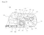
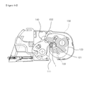
- a latch assembly for a vehicle seat 100 comprises a base 110, a catch 120 and a damping plate 130 which are rotatably coupled to the base with the same rotating axis therebetween, and a pawl plate 140 and a pawl 150 which are rotatably coupled to the base 110 at an opposite side of the catch 120 with the same rotating axis therebetween.
- the base 110 supports other components of the latch assembly 100.
- the base 110 has a receiving pocket 111 at its lower side to receive and support a striker 1 (refer to FIG. 3 ) at a vehicle body.
- the catch 120 is rotatably coupled to the base 110 with a rotating center at O1.
- the catch 120 rotates between a locking position (refer to FIG. 7 ) where it supports the striker 1 inserted in the receiving pocket 111 and an unlocking position (refer to FIG. 2 ) where it allows the striker 1 to escape from the receiving pocket 111.
- the catch 120 has a catch pocket 121 to receive and support the striker 1 inserted in the receiving pocket 111.
- the catch 120 has a structure of two guiding surfaces 123 and 125 (refer to FIG. 5 ) of different layers therebetween to interact with the pawl plate 140 and the pawl 150.
- the catch 120 may be formed by overlapping and combining two plate members having the guide surfaces 123 and 125 or formed as one body having the two layers by injection molding or etc.
- the damping plate 130 is rotated around the same rotating axis O1 as the catch 120.
- the damping plate 130 and the catch 120 are coupled together by pin-slot coupling through a slot 131 and a pin 122.
- the damping plate 130 With the above coupling state with the catch 120, the damping plate 130 is always pressed counterclockwise by a spring 101, so that the damping plate 130 presses the catch 120 to rotate counterclockwise, that is toward the unlocking position, through the pin 122 and slot 131 coupling.
- the damping plate 130 can rotate further counterclockwise with regard to the catch 120 as much as a path of the slot 131 due to the pin 122 and slot 131 coupling with the catch 120, so that the damping plate 130 can have a damping surface 132 to protrude into an inner space of the catch pocket 121. Through the damping surface 132, the damping plate 130 can press and support the striker 1 accommodated in the catch pocket 121.
- the pawl plate 140 and the pawl 150 rotate around a rotating center 02, which is provided at a left side of the receiving pocket 111 in the base 110, to interact with the catch 120.
- the pawl plate 140 is pressed by a spring 102 to rotate clockwise, and maintains a stable locking state of the catch 120 through a pressing surface 141 which presses and supports the catch 120 rotated to the locking position.
- the pawl 150 is pressed by a spring 103 to rotate clockwise. Also, when the catch 120 at the locking position starts rotating counterclockwise, that is toward the unlocking position, by passing the pressing surface 141 of the pawl plate 140 due to an outer impact, the pawl 150 prevents the catch 120 from further rotating through a supporting surface 151 supporting the catch 120.
- the latch assembly for a vehicle seat 100 further comprises a lever 160 to operate the counterclockwise rotations of the pawl plate 140 and the pawl 150.
- the lever 160 rotates around a rotating center 03 and has at its right end a pin 161 which is inserted into a recess 152 of the pawl 150 as well as accommodated in a slot 142 of the pawl plate 140.
- the pawl 150 and the pawl plate 140 rotate counterclockwise and release the catch 120 at the locking position, so that the catch 120 can be unlocked and rotate counterclockwise, that is, in the unlocking direction.
- the lever 160 has at its lower end part a protrusion 162 which is combined with a red flag 170.
- the red flag 170 protrudes to the left to inform that the latch assembly 100 is in the unlocking state (refer to FIG. 2 ).
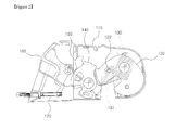
- FIG. 2 shows a state of the latch assembly 100 where the catch 120 is rotated to the unlocking position.
- the catch 120 can rotate to the unlocking position due to a counterclockwise elastic pressure from the damping plate 130 which is pin(122)-slot(131) coupled to the catch 120.
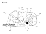
- FIGS. 3 to 7 show a locking process of the latch assembly 100 by stages.
- the striker 1 of a vehicle chassis part rises from a lower outside of the receiving pocket 111 and is inserted into the inside of the receiving pocket 111. While being inserted, the striker 1 contacts first the damping surface 132 of the damping plate 130 which has been protruding to the inside of the catch pocket 121.
- the damping plate 130 rotates elastically clockwise while being in contact with the striker 1.
- the damping plate 130 is rotated clockwise by the striker 1, the catch 120 maintains its unlocking position due to the pin(122)-slot(131) coupling with the damping plate 130.
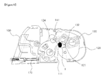
- FIG. 4 shows both the damping plate 130 and the catch 120 contacting the striker 1 after the damping plate 130 has been rotated. Thereafter, the damping plate 130 rotates clockwise together with the catch 120.
- FIG. 5 shows a tip 143 of the pawl plate 140 contacting an upper end part of a first guiding surface 123 of the catch 120 due to the rotation of the catch 120.
- the catch 120 rotates further, the first guiding surface 123 to its lower end part is in contact with the tip 143.
- FIG. 6 shows an end of the clockwise rotation of the catch 120 due to the pressure of the rising striker 1.
- the tip 143 of the pawl plate 140 passes the lower end part of the first guiding surface 123 and enter a neighboring locking surface 124 of the catch 120, which is done by a small clockwise rotation of the pawl plate 140 that is always pressed clockwise by the spring 102 (refer to FIG. 1 ) and during this process a right end part of the pressing surface 141 also contacts an end part of the locking surface 124 of the catch 120.
- the pawl 150 contacts and slides on an upper end part 125a of a second guiding surface 125 of the rotating catch 120 as shown in FIG. 5 , and then a lower end part 125b of the second guiding surface 125 passes a tip 153 of the pawl 150 thus the pawl 150 rotating as shown in FIG. 6 , so that its supporting surface 151 contacts the locking surface 124 of the catch 120.
- the catch 120 has a two layer structure comprising the first guiding surface 123 and the second guiding surface 125 as its surfaces to interact with the pawl plate 140 and the pawl 150.
- the pressure of the striker 1 onto the catch 120 and the damping plate 130 ends when the striker 1 reaches an upper end of the receiving pocket 111 as shown in FIG. 6 .
- the pawl plate 140 further rotates clockwise according to the pressure of the spring 102 (refer to FIG. 1 ), then the pressing surface 141 presses the locking surface 124 of the catch 120 so that the catch 120 can further rotate to its position in FIG. 7 .
- the damping plate 130 can still maintain to contact and press the striker 1 because of the pin(122)-slot(131) coupling with the catch 120.
- the striker is supported by the receiving pocket 1111 at its upper end part and by the catch pocket 121 at its lower end part and additionally supported by the damping surface 132 of the damping plate 130.
- the catch 120 as the catch 120 is pressed by the pressing surface 141 of the pawl plate 140 in its locking position, it can accommodate the striker 1 as far as it is pressed and rotated by the pressing surface 141 even though there are errors in the size or the locking position of the striker 1, in the manufacturing allowances of the latch assembly 100 and etc.
- the latch assembly 100 has a room for the manufacturing allowances to some extent within the accommodating space for the striker 1, the space is provided by the receiving pocket 111 and the catch pocket 121 in FIG. 6 .
- the striker 1 in the locking state is still supported by the receiving pocket 111, the catch pocket 121 and the damping surface 132, where there is only a change in the position where the pressing surface 141 presses and supports the locking surface 124 of the catch 120.
- a normal direction of the force F which is applied by the pawl plate 140 through its pressing surface 141 onto the locking surface 124 of the catch 120 forms a predetermined pressure angle ⁇ with a center line drawn to the rotating center 02.
- the pressing surface 141 is a part of an arc which has its center O2' on the normal line of the force F.
- the pawl plate 140 When the outer impact through the catch 120 exceeds the supporting force F, the pawl plate 140 is pressed by the catch 120 and rotates counterclockwise as shown in FIG. 10 .
- the locking surface 124 of the catch 120 is supported by the supporting surface 151 of the pawl 150.
- the locking surface 124 of the catch 120 is also supported by the second supporting surface 144 of the pawl plate 140.
- the catch 120 is doubly supported in case of the outer impact thus enhancing a safety in use.
- one side part of the damping plate 130 including the damping surface 132 which supports the striker 1 has a thickness t to be bigger than other part of the damping plate 130 to enlarge an area of the damping surface 132 for pressing and supporting the striker 1.
- a noise due to a generation of a clearance from the locked striker 1 can be absorbed to some extent, so that a generation of the noise can be decreased.
- the damping plate 130 can be made by integrally forming a steel plate 130a and a plastic plate 130b. Accordingly, the thickness of the damping surface 132 can be easily provided by forming the part comprising the damping surface 132 with the plastic plate. Also, the noise generated between the damping surface 132 and the striker 1 can be much decreased.
- the unlocking process of the latch assembly 100 according to the first exemplary embodiment of the present invention is in reverse order to the locking process described above.
- the catch 120 does not have its own elastic pressing means but is pressed elastically by the damping plate 130 in the unlocking direction. Accordingly, in the locking state of FIG. 7 , the catch 120 exerts substantially no force of its own onto the pawl plate 140 as far as the damping plate 130 is supported and stopped by the striker 1.
- the force required for the unlocking operation that is the operation for the counterclockwise rotation, of the pawl plate 130 which has been supporting the catch 120 decreases as much, so that the user's operation of the lever 160 for the unlocking can be easily performed.
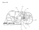
- FIGS. 12 to 16 show a locking process of a latch assembly for a vehicle seat according to a second exemplary embodiment of the present invention by stages.
- a damping plate 130 of the latch assembly for a vehicle seat has a damping pocket 133 which includes as its part the damping surface 132 described above.
- the damping pocket 133 is for accommodating and supporting the striker 1 which is accommodated in the receiving pocket 111.
- the striker 1 of the vehicle body first contacts the damping surface 132 of the damping plate 130.
- FIG. 15 shows an end of the clockwise rotation of the catch 120 due to the pressure of the rising striker 1.
- the striker 1 is accommodated in the damping pocket 133 of the damping plate 130 and supported by both an upper end part of the damping pocket 133, that is the damping surface 132, and a lower end part of the damping pocket 133.
- the pressure of the striker 1 onto the catch 120 and the damping plate 130 terminates when the striker 1 reaches an upper end part of the receiving pocket 111 as shown in FIG. 15 . Thereafter, the process of the rotation of the catch 120 from FIG. 15 to FIG. 16 is caused by the pawl plate 140 as described in the first exemplary embodiment of the present invention.
- a lower end part of the striker 1 contacts and is supported by the catch pocket 121 and the damping pocket 133. Also, an upper end part of the striker 1 is supported by the receiving pocket 111 and the damping surface 132.
- the latch assembly has a room for the manufacturing allowances to some extent within the accommodating space for the striker 1, the space is provided by the receiving pocket 111 and the catch pocket 121 in FIG. 15 .
- the striker 1 in the locking state is still supported by the receiving pocket 111, the catch pocket 121 and the damping surface 132, where there is only a change in the position where the pressing surface 141 presses and supports the locking surface 124 of the catch 120.
- the damping plate 130 has a thickness t of the damping pocket 133 which includes the damping surface 132 supporting the striker 1. As shown in FIG. 19 , the thickness t is provided to be bigger than any other part of the damping plate 130, so that an area of the damping pocket 133 for accommodating and supporting the striker 1 is increased.
- the damping plate 130 can be made by integrally forming a steel plate 130a and a plastic plate 130b.
- the latch assembly for a vehicle seat described above can be provided on a seatback for locking and unlocking the seatback onto a vehicle body part.
- the latch assembly according to the present invention is not limited for that use but can also be provided on a seat cushion for locking and unlocking a whole seat onto the vehicle body part.
Abstract
Description
- The present invention relates to a latch assembly for a vehicle seat, and more particularly, to a latch assembly mounted to a vehicle seat to assemble and disassemble the vehicle seat to and from a vehicle body.
- A latch assembly for a vehicle seat is an apparatus for assembling and disassembling a vehicle seat to and from a vehicle body.
- Among various requirements for such a latch assembly for a vehicle seat, it is required that a coupling state of the latch assembly for a vehicle seat should be certainly maintained even though an impact is applied through the vehicle body, that is, safety.
- It is also required that when there are a lot of variables in coupling the latch assembly, for example, when there are manufacturing tolerances related to the coupling of the latch assembly, the latch assembly should operate without difficulty by extensively accommodating the manufacturing tolerances.
- Especially, in addition to the above requirements, the latch assembly for a vehicle seat is required to be easily operated with only a small operating force and to prevent a generation of rattling noise due to clearances in its coupled state.
- To satisfy the above requirements, a lot of technologies have been developed, and among latch assemblies in use now, a technology having a base, a catch rotatably coupled to the base and a pawl rotatably coupled to the base to interact with the catch has been introduced.
- Nevertheless, there has still been a demand for an improved latch assembly for a vehicle seat to satisfy the above requirements.
- The present invention is proposed to satisfy the above requirements for a latch assembly for a vehicle seat and it is an aspect of the present invention to provide a latch assembly for a vehicle seat which can operate without difficulty even if there are errors to some degree in a coupling condition as well as provide safety, which can accommodate an operating convenience by enabling a smooth operation with only a small operating force, and which can prevent a generation of rattling noise due to clearances in its coupled state.
- The foregoing and/or other aspects of the present invention can be achieved by providing a latch assembly for vehicle seat, comprising: a base having a receiving pocket for accommodating a striker of a vehicle body part; a catch rotatably coupled to the base to rotate between a locking position where the catch supports the striker accommodated in the receiving pocket and an unlocking position where the catch allows the striker to escape from the receiving pocket; a damping plate rotatably coupled to the base with the same rotating axis as the catch to elastically press the catch to rotate to the unlocking position and having a damping surface which elastically presses and supports the striker accommodated in the receiving pocket; a pawl plate rotatably coupled to the base and having a pressing surface which presses the catch rotated to the locking position; and a pawl rotatably couple to the base with the same rotating axis as the pawl plate and having a supporting surface which supports the catch to prevent a further rotation of the catch if the catch at the locking position starts rotating by passing the pressing surface of the pawl plate due to an outer impact.
- According to an aspect of the present invention, the damping plate and the cam are rotatable therebetween to a predetermined degree of angle through a pin which is provided at one of the damping plate and the cam and a slot which is provided at the other of the damping plate and the cam to couple with the pin.
- According to an aspect of the present invention, the pin is provided to the catch and the slot is provided to the damping plate.
- According to an aspect of the present invention, the catch has a catch pocket which, at the locking position of the catch, accommodates and supports the striker accommodated in the receiving pocket of the base, and the damping surface of the damping plate, at the locking position of the catch, elastically presses and supports the striker accommodated in the receiving pocket in a state that the damping surface protrudes into an inside of the catch pocket.
- According to an aspect of the present invention, at least a side part of the damping plate including the damping surface has a thickness bigger than any other part thereof, so that an area of the damping surface for pressing and supporting the striker is increased.
- According to an aspect of the present invention, at least a part of the damping plate including the damping surface is made of a plastic resin.
- According to an aspect of the present invention, the damping plate has a damping pocket which, at the locking position of the catch, accommodates and supports the striker accommodated in the receiving pocket, and the damping pocket includes the damping surface as a part thereof.
- According to an aspect of the present invention, the damping plate has at least one side part that includes the damping surface, having a thickness bigger than any other part of the damping plate, so that an area of the damping surface for pressing and supporting the striker and an area of the damping pocket for accommodating and supporting the striker are increased.
- According to an aspect of the present invention, at least one part of the damping plate, that includes the damping pocket, is made of a plastic resin.
- According to an aspect of the present invention, the catch has a locking surface which at the locking position of the catch is supported by the pressing surface of the pawl plate, and the pressing surface of the pawl plate is a part of an arc whose center is at a distance from a rotating center of the pawl plate and forms a predetermined pressure angle by contacting the locking surface if the catch is at the locking position.
- According to an aspect of the present invention, the pawl plate has a second supporting surface to support the catch together with the supporting surface of the pawl if the catch at the locking position starts rotating by passing the pressing surface of the pawl plate due to the outer impact.
- According to an aspect of the present invention, at the locking position of the catch the striker accommodated in the receiving pocket of the base is supported by the receiving pocket, the catch and the damping plate at the same time.
- The latch assembly for vehicle seat according to the present invention described above has, when a catch is locked to a striker, not only a pawl plate to support the catch but also a pawl to additionally support the catch in case of an impact thus preventing more effectively a release of a locking state and providing a more enhanced safety.
- Also, the pawl plate presses the catch while the striker is locked by the catch, so that the striker can maintain its state of being contacted and supported by the catch even if a locking position of the striker is a little changed. Therefore, the latch assembly for a vehicle seat according to the present invention can operate without difficulty even if there are errors to some degree in a coupling condition of the striker.
- Also, a damping plate presses and supports the striker elastically when the catch locks the striker, a generation of a rattling noise induced by the striker having clearances in its locked state can be prevented.
- Also, as the catch is not provided with its own spring for its rotation but is elastically pressed and rotated by the damping plate, it doesn't have to substantially press the pawl plate supporting the catch when the damping plate is stopped by the striker in a locking state with a condition that the catch and the damping plate is coupled together by pin and slot. Accordingly, a force of the pawl plate supporting the catch is reduced, and a force required for an unlocking operation of the pawl plate which has been supporting the catch in the locking state can also be reduced so much. Therefore, a user can easily and conveniently perform the unlocking operation.
-
-
FIG. 1 is a plan view showing an inside of a latch assembly for a vehicle seat according to a first exemplary embodiment of the present invention; -
FIG. 2 is a plan view showing an unlocking state of the latch assembly for a vehicle seat inFIG. 1 ; -
FIGS. 3 to 7 are plan views showing a locking process of the latch assembly for a vehicle seat by stages from the unlocking state ofFIG. 2 ; -
FIG. 8 andFIG. 9 show locking states of the latch assembly for a vehicle seat inFIG. 1 under different locking conditions; -
FIG. 10 shows a state of the latch assembly for a vehicle seat inFIG. 7 with an impact thereon; -
FIG. 11 is an expanded perspective view of a component of the latch assembly for a vehicle seat inFIG. 1 ; -
FIGS. 12 to 16 are plan views showing a locking process of a latch assembly for a vehicle seat according to a second exemplary embodiment of the present invention by stages from an unlocking state of the latch assembly; -
FIG. 17 andFIG. 18 show locking states of the latch assembly for a vehicle seat according to the second exemplary embodiment of the present invention under different locking conditions; and -
FIG. 19 is an expanded perspective view of a component of the latch assembly for a vehicle seat according to the second exemplary embodiment of the present invention. - A latch assembly for a
vehicle seat 100 according to a first exemplary embodiment of the present invention, as shown inFIG. 1 , comprises abase 110, acatch 120 and adamping plate 130 which are rotatably coupled to the base with the same rotating axis therebetween, and apawl plate 140 and apawl 150 which are rotatably coupled to thebase 110 at an opposite side of thecatch 120 with the same rotating axis therebetween. - The
base 110 supports other components of thelatch assembly 100. Thebase 110 has a receivingpocket 111 at its lower side to receive and support a striker 1 (refer toFIG. 3 ) at a vehicle body. - The
catch 120 is rotatably coupled to thebase 110 with a rotating center at O1. Thecatch 120 rotates between a locking position (refer toFIG. 7 ) where it supports thestriker 1 inserted in the receivingpocket 111 and an unlocking position (refer toFIG. 2 ) where it allows thestriker 1 to escape from thereceiving pocket 111. - The
catch 120 has acatch pocket 121 to receive and support thestriker 1 inserted in the receivingpocket 111. - The
catch 120 has a structure of two guidingsurfaces 123 and 125 (refer toFIG. 5 ) of different layers therebetween to interact with thepawl plate 140 and thepawl 150. - To form such a structure of two layers, the
catch 120 may be formed by overlapping and combining two plate members having theguide surfaces - The
damping plate 130 is rotated around the same rotating axis O1 as thecatch 120. Thedamping plate 130 and thecatch 120 are coupled together by pin-slot coupling through aslot 131 and apin 122. - With the above coupling state with the
catch 120, thedamping plate 130 is always pressed counterclockwise by aspring 101, so that thedamping plate 130 presses thecatch 120 to rotate counterclockwise, that is toward the unlocking position, through thepin 122 andslot 131 coupling. - Also, the
damping plate 130 can rotate further counterclockwise with regard to thecatch 120 as much as a path of theslot 131 due to thepin 122 andslot 131 coupling with thecatch 120, so that thedamping plate 130 can have adamping surface 132 to protrude into an inner space of thecatch pocket 121. Through thedamping surface 132, thedamping plate 130 can press and support thestriker 1 accommodated in thecatch pocket 121. - The
pawl plate 140 and thepawl 150 rotate around a rotating center 02, which is provided at a left side of the receivingpocket 111 in thebase 110, to interact with thecatch 120. - The
pawl plate 140 is pressed by aspring 102 to rotate clockwise, and maintains a stable locking state of thecatch 120 through apressing surface 141 which presses and supports thecatch 120 rotated to the locking position. - The
pawl 150 is pressed by aspring 103 to rotate clockwise. Also, when thecatch 120 at the locking position starts rotating counterclockwise, that is toward the unlocking position, by passing thepressing surface 141 of thepawl plate 140 due to an outer impact, thepawl 150 prevents thecatch 120 from further rotating through a supportingsurface 151 supporting thecatch 120. - The latch assembly for a
vehicle seat 100 according to the first exemplary embodiment of the present invention further comprises alever 160 to operate the counterclockwise rotations of thepawl plate 140 and thepawl 150. - The
lever 160 rotates around a rotating center 03 and has at its right end apin 161 which is inserted into arecess 152 of thepawl 150 as well as accommodated in aslot 142 of thepawl plate 140. - Therefore, if the
lever 160 rotates clockwise by a user's operation, thepawl 150 and thepawl plate 140 rotate counterclockwise and release thecatch 120 at the locking position, so that thecatch 120 can be unlocked and rotate counterclockwise, that is, in the unlocking direction. - The
lever 160 has at its lower end part aprotrusion 162 which is combined with ared flag 170. In case of an unlocking operation of thelever 160, thered flag 170 protrudes to the left to inform that thelatch assembly 100 is in the unlocking state (refer toFIG. 2 ). -
FIG. 2 shows a state of thelatch assembly 100 where thecatch 120 is rotated to the unlocking position. - As described above, the
catch 120 can rotate to the unlocking position due to a counterclockwise elastic pressure from the dampingplate 130 which is pin(122)-slot(131) coupled to thecatch 120. -
FIGS. 3 to 7 show a locking process of thelatch assembly 100 by stages. - At first, referring to
FIG. 3 , thestriker 1 of a vehicle chassis part rises from a lower outside of the receivingpocket 111 and is inserted into the inside of the receivingpocket 111. While being inserted, thestriker 1 contacts first the dampingsurface 132 of the dampingplate 130 which has been protruding to the inside of thecatch pocket 121. - If the
striker 1 rises further, as shown inFIG. 4 , the dampingplate 130 rotates elastically clockwise while being in contact with thestriker 1. - Although, during a process from
FIG. 3 to FIG. 4 , the dampingplate 130 is rotated clockwise by thestriker 1, thecatch 120 maintains its unlocking position due to the pin(122)-slot(131) coupling with the dampingplate 130. -
FIG. 4 shows both the dampingplate 130 and thecatch 120 contacting thestriker 1 after the dampingplate 130 has been rotated. Thereafter, the dampingplate 130 rotates clockwise together with thecatch 120. -
FIG. 5 shows atip 143 of thepawl plate 140 contacting an upper end part of afirst guiding surface 123 of thecatch 120 due to the rotation of thecatch 120. - Thereafter, as the
catch 120 rotates further, thefirst guiding surface 123 to its lower end part is in contact with thetip 143. -
FIG. 6 shows an end of the clockwise rotation of thecatch 120 due to the pressure of the risingstriker 1. Thereafter, thetip 143 of thepawl plate 140 passes the lower end part of thefirst guiding surface 123 and enter a neighboringlocking surface 124 of thecatch 120, which is done by a small clockwise rotation of thepawl plate 140 that is always pressed clockwise by the spring 102 (refer toFIG. 1 ) and during this process a right end part of thepressing surface 141 also contacts an end part of the lockingsurface 124 of thecatch 120. - Meanwhile, the
pawl 150 contacts and slides on anupper end part 125a of asecond guiding surface 125 of therotating catch 120 as shown inFIG. 5 , and then alower end part 125b of thesecond guiding surface 125 passes atip 153 of thepawl 150 thus thepawl 150 rotating as shown inFIG. 6 , so that its supportingsurface 151 contacts the lockingsurface 124 of thecatch 120. - As it can be seen from the above description, the
catch 120 has a two layer structure comprising thefirst guiding surface 123 and thesecond guiding surface 125 as its surfaces to interact with thepawl plate 140 and thepawl 150. - The pressure of the
striker 1 onto thecatch 120 and the dampingplate 130 ends when thestriker 1 reaches an upper end of the receivingpocket 111 as shown inFIG. 6 . - Thereafter, the process of the rotation of the
catch 120 fromFIG. 6 to FIG. 7 is caused by thepawl plate 140. - That is, from the state of
FIG. 6 , thepawl plate 140 further rotates clockwise according to the pressure of the spring 102 (refer toFIG. 1 ), then thepressing surface 141 presses the lockingsurface 124 of thecatch 120 so that thecatch 120 can further rotate to its position inFIG. 7 . - Due to the further rotation of the
catch 120, a lower end part of thestriker 1 contacts thecatch pocket 121 and is supported thereby. - Meanwhile, although the
catch 120 rotates during the process fromFIG. 6 to FIG. 7 , the dampingplate 130 can still maintain to contact and press thestriker 1 because of the pin(122)-slot(131) coupling with thecatch 120. - Therefore, the striker is supported by the receiving pocket 1111 at its upper end part and by the
catch pocket 121 at its lower end part and additionally supported by the dampingsurface 132 of the dampingplate 130. - Also, as described above, as the
catch 120 is pressed by thepressing surface 141 of thepawl plate 140 in its locking position, it can accommodate thestriker 1 as far as it is pressed and rotated by thepressing surface 141 even though there are errors in the size or the locking position of thestriker 1, in the manufacturing allowances of thelatch assembly 100 and etc. - That is, the
latch assembly 100 has a room for the manufacturing allowances to some extent within the accommodating space for thestriker 1, the space is provided by the receivingpocket 111 and thecatch pocket 121 inFIG. 6 . - For example, when the
striker 1 is locked not only at the left end part of the receivingpocket 111 as shown inFIG. 8 but also at the right end part thereof as shown inFIG. 9 , thestriker 1 in the locking state is still supported by the receivingpocket 111, thecatch pocket 121 and the dampingsurface 132, where there is only a change in the position where thepressing surface 141 presses and supports the lockingsurface 124 of thecatch 120. - In the locking state of
FIG. 7 , a normal direction of the force F which is applied by thepawl plate 140 through itspressing surface 141 onto the lockingsurface 124 of thecatch 120 forms a predetermined pressure angle α with a center line drawn to the rotating center 02. Thepressing surface 141 is a part of an arc which has its center O2' on the normal line of the force F. - With the pressure angle a, even if the
pawl plate 140 receives an impact from thecatch 120 through thepressing surface 141, it does not directly rotate counterclockwise but absorbs the impact to some extent through the center O2. - If the pressure angle α increases, the supporting force F of the
pressing surface 141 decreases. On the contrary, if the pressure angle α decreases, the supporting force F increases. - When the outer impact through the
catch 120 exceeds the supporting force F, thepawl plate 140 is pressed by thecatch 120 and rotates counterclockwise as shown inFIG. 10 . - Accordingly, the locking
surface 124 of thecatch 120 is supported by the supportingsurface 151 of thepawl 150. - At the same time, the locking
surface 124 of thecatch 120 is also supported by the second supportingsurface 144 of thepawl plate 140. - Therefore, the
catch 120 is doubly supported in case of the outer impact thus enhancing a safety in use. - As shown in
FIG. 11 , one side part of the dampingplate 130 including the dampingsurface 132 which supports thestriker 1 has a thickness t to be bigger than other part of the dampingplate 130 to enlarge an area of the dampingsurface 132 for pressing and supporting thestriker 1. - Therefore, a noise due to a generation of a clearance from the locked
striker 1 can be absorbed to some extent, so that a generation of the noise can be decreased. - Also, as shown in
FIG. 11 , the dampingplate 130 can be made by integrally forming asteel plate 130a and aplastic plate 130b. Accordingly, the thickness of the dampingsurface 132 can be easily provided by forming the part comprising the dampingsurface 132 with the plastic plate. Also, the noise generated between the dampingsurface 132 and thestriker 1 can be much decreased. - The unlocking process of the
latch assembly 100 according to the first exemplary embodiment of the present invention is in reverse order to the locking process described above. - To briefly describe the unlocking process, if the
lever 160 rotates clockwise due to the user's operation in the locking state ofFIG. 7 , thepawl 150 and thepawl plate 140 rotate counterclockwise in order, so that thepawl 150, the states of thepawl plate 140 and thecatch 120 are changed into those shown inFIG. 4 . - Thereafter, the
striker 1 is drawn downward out of the receivingpocket 111, so that the unlocking state ofFIG. 2 can be accomplished. - The
catch 120 does not have its own elastic pressing means but is pressed elastically by the dampingplate 130 in the unlocking direction. Accordingly, in the locking state ofFIG. 7 , thecatch 120 exerts substantially no force of its own onto thepawl plate 140 as far as the dampingplate 130 is supported and stopped by thestriker 1. - Therefore, the force required for the unlocking operation, that is the operation for the counterclockwise rotation, of the
pawl plate 130 which has been supporting thecatch 120 decreases as much, so that the user's operation of thelever 160 for the unlocking can be easily performed. -
FIGS. 12 to 16 show a locking process of a latch assembly for a vehicle seat according to a second exemplary embodiment of the present invention by stages. - In the figures, the elements and parts that are the same as those in the first exemplary embodiment described above will have the same numerals. Also, a repetition of the same description as in the first exemplary embodiment of the present invention above will be skipped in this second exemplary embodiment of the present invention.
- At first, as shown in
FIG. 12 , a dampingplate 130 of the latch assembly for a vehicle seat according to the second exemplary embodiment of the present invention has a dampingpocket 133 which includes as its part the dampingsurface 132 described above. - As will be described later, the damping
pocket 133 is for accommodating and supporting thestriker 1 which is accommodated in the receivingpocket 111. - To describe the locking process, while being inserted into the receiving
pocket 111, thestriker 1 of the vehicle body first contacts the dampingsurface 132 of the dampingplate 130. - Due to an additional rise of the
striker 1, as shown inFIGS. 13 and14 , the dampingplate 130 and thecatch 120 contact thestriker 1 together and rotate clockwise. -
FIG. 15 shows an end of the clockwise rotation of thecatch 120 due to the pressure of the risingstriker 1. In this case, thestriker 1 is accommodated in the dampingpocket 133 of the dampingplate 130 and supported by both an upper end part of the dampingpocket 133, that is the dampingsurface 132, and a lower end part of the dampingpocket 133. - The pressure of the
striker 1 onto thecatch 120 and the dampingplate 130 terminates when thestriker 1 reaches an upper end part of the receivingpocket 111 as shown inFIG. 15 . Thereafter, the process of the rotation of thecatch 120 fromFIG. 15 to FIG. 16 is caused by thepawl plate 140 as described in the first exemplary embodiment of the present invention. - Due to such further rotation of the
catch 120, a lower end part of thestriker 1 contacts and is supported by thecatch pocket 121 and the dampingpocket 133. Also, an upper end part of thestriker 1 is supported by the receivingpocket 111 and the dampingsurface 132. - Of course, the latch assembly according to this exemplary embodiment has a room for the manufacturing allowances to some extent within the accommodating space for the
striker 1, the space is provided by the receivingpocket 111 and thecatch pocket 121 inFIG. 15 . - For example, when the
striker 1 is locked not only at the left end part of the receivingpocket 111 as shown inFIG. 17 but also at the right end part thereof as shown inFIG. 18 , thestriker 1 in the locking state is still supported by the receivingpocket 111, thecatch pocket 121 and the dampingsurface 132, where there is only a change in the position where thepressing surface 141 presses and supports the lockingsurface 124 of thecatch 120. - In this exemplary embodiment, the damping
plate 130 has a thickness t of the dampingpocket 133 which includes the dampingsurface 132 supporting thestriker 1. As shown inFIG. 19 , the thickness t is provided to be bigger than any other part of the dampingplate 130, so that an area of the dampingpocket 133 for accommodating and supporting thestriker 1 is increased. - Therefore, a noise due to a generation of a clearance from the locked
striker 1 can be decreased. - Also, the damping
plate 130 can be made by integrally forming asteel plate 130a and aplastic plate 130b. - The latch assembly for a vehicle seat described above can be provided on a seatback for locking and unlocking the seatback onto a vehicle body part. However, the latch assembly according to the present invention is not limited for that use but can also be provided on a seat cushion for locking and unlocking a whole seat onto the vehicle body part.
- Although the latch assembly for a vehicle seat according to the exemplary embodiments of the present invention has been shown, it will be appreciated by those skilled in the art that changes may be made in the exemplary embodiment without departing from the principles and spirit of the invention, the scope of which is defined in the appended claims and their equivalents.
Claims (12)
- A latch assembly for vehicle seat, comprising:a base having a receiving pocket for accommodating a striker of a vehicle body;a catch rotatably coupled to the base to rotate between a locking position where the catch supports the striker accommodated in the receiving pocket and an unlocking position where the catch allows the striker to escape from the receiving pocket;a damping plate rotatably coupled to the base with the same rotating axis as the catch to elastically press the catch to rotate to the unlocking position and having a damping surface to elastically press and support the striker accommodated in the receiving pocket;a pawl plate rotatably coupled to the base and having a pressing surface to press the catch rotated to the locking position; anda pawl rotatably couple to the base with the same rotating axis as the pawl plate and having a supporting surface to support the catch to prevent a further rotation of the catch when the catch at the locking position starts rotating by passing the pressing surface of the pawl plate due to an outer impact.
- The latch assembly for vehicle seat according to claim 1 wherein the damping plate and the catch are rotatable therebetween to a predetermined degree of angle through a pin which is provided at one of the damping plate and the catch and a slot which is provided at the other of the damping plate and the catch to couple with the pin.
- The latch assembly for vehicle seat according to claim 2 wherein the pin is provided at the catch and the slot is provided at the damping plate.
- The latch assembly for vehicle seat according to one of the claim 1 to claim 3 wherein the catch has a catch pocket which, at the locking position of the catch, accommodates and supports the striker accommodated in the receiving pocket of the base, and
the damping surface of the damping plate elastically presses and supports, at the locking position of the catch, the striker accommodated in the receiving pocket in a state that the damping surface protrudes into the catch pocket. - The latch assembly for vehicle seat according to claim 4 wherein at least one side part of the damping plate, that includes the damping surface, has a thickness bigger than any other part of the damping plate, so that an area of the damping surface for pressing and supporting the striker is increased.
- The latch assembly for vehicle seat according to claim 5 wherein at least one part of the damping plate, that includes the damping surface, is made of a plastic resin.
- The latch assembly for vehicle seat according to claim 4 wherein the damping plate has a damping pocket which, at the locking position of the catch, accommodates and supports the striker accommodated in the receiving pocket, and
the damping pocket includes the damping surface as a part thereof. - The latch assembly for vehicle seat according to claim 7 wherein the damping plate has at least one side part that includes the damping surface, having a thickness bigger than any other part of the damping plate, so that an area of the damping surface for pressing and supporting the striker and an area of the damping pocket for accommodating and supporting the striker are increased.
- The latch assembly for vehicle seat according to claim 8 wherein at least one part of the damping plate, that includes the damping pocket, is made of a plastic resin.
- The latch assembly for vehicle seat according to claim 1 wherein the catch has a locking surface which at the locking position of the catch is supported by the pressing surface of the pawl plate, and
the pressing surface of the pawl plate is a part of an arc whose center is at a distance from a rotating center of the pawl plate, so that the pressing surface forms a predetermined pressure angle when it contacts the locking surface at the locking position of the catch. - The latch assembly for vehicle seat according to claim 1 wherein the pawl plate has a second supporting surface to support the catch together with the supporting surface of the pawl if the catch at the locking position starts rotating by passing the pressing surface of the pawl plate due to the outer impact.
- The latch assembly for vehicle seat according to claim 1 wherein at the locking position of the catch the striker accommodated in the receiving pocket of the base is supported by the receiving pocket, the catch and the damping plate at the same time.
Applications Claiming Priority (3)
| Application Number | Priority Date | Filing Date | Title |
|---|---|---|---|
| KR20090030135 | 2009-04-08 | ||
| KR1020100014622A KR101072788B1 (en) | 2009-04-08 | 2010-02-18 | Latch assembly for vehicle seat |
| PCT/KR2010/001105 WO2010117138A2 (en) | 2009-04-08 | 2010-02-23 | Latch assembly for a vehicle seat |
Publications (2)
| Publication Number | Publication Date |
|---|---|
| EP2418119A2 true EP2418119A2 (en) | 2012-02-15 |
| EP2418119A4 EP2418119A4 (en) | 2017-11-22 |
Family
ID=43132152
Family Applications (1)
| Application Number | Title | Priority Date | Filing Date |
|---|---|---|---|
| EP10761799.5A Withdrawn EP2418119A4 (en) | 2009-04-08 | 2010-02-23 | Latch assembly for a vehicle seat |
Country Status (5)
| Country | Link |
|---|---|
| US (2) | US7959205B2 (en) |
| EP (1) | EP2418119A4 (en) |
| KR (1) | KR101072788B1 (en) |
| CN (1) | CN102481869B (en) |
| WO (1) | WO2010117138A2 (en) |
Cited By (3)
| Publication number | Priority date | Publication date | Assignee | Title |
|---|---|---|---|---|
| EP2852509A4 (en) * | 2012-05-23 | 2016-01-27 | Porter Group Llc | Vehicle seat latch having striker compliance in transverse directions |
| CN109572502A (en) * | 2018-11-20 | 2019-04-05 | 长春汽富维安道拓汽车金属零部件有限公司 | Automobile rear backrest lockable mechanism |
| CZ308058B6 (en) * | 2018-10-05 | 2019-11-27 | Brano As | Seat lock |
Families Citing this family (37)
| Publication number | Priority date | Publication date | Assignee | Title |
|---|---|---|---|---|
| CN101668916B (en) * | 2007-02-28 | 2017-07-28 | 马格纳·克劳祖雷斯有限公司 | Modular latch |
| JP5624886B2 (en) * | 2007-09-11 | 2014-11-12 | ジョンソン コントロールズテクノロジーカンパニーJohnson Controls Technology Company | Vehicle seat |
| WO2009069851A1 (en) * | 2007-11-27 | 2009-06-04 | Austem Co., Ltd. | Latch assembly for vehicle seat |
| DE102008033304B4 (en) * | 2008-07-11 | 2018-01-04 | Adient Luxembourg Holding S.à.r.l. | Locking device for a vehicle seat and vehicle seat |
| DE102008033305B4 (en) * | 2008-07-11 | 2019-06-27 | Adient Luxembourg Holding S.À R.L. | Locking device for a vehicle seat and vehicle seat |
| US7959205B2 (en) * | 2009-04-08 | 2011-06-14 | Austem Co., Ltd. | Latch assembly for vehicle seat |
| US8596696B2 (en) * | 2010-02-24 | 2013-12-03 | Magna Closures S.P.A. | Vehicular latch with single notch ratchet |
| WO2011123127A1 (en) * | 2010-04-01 | 2011-10-06 | Lear Corporation | Latch mechanism for releasably securing a seat to a floor |
| US8851548B2 (en) | 2011-02-10 | 2014-10-07 | Bae Industries, Inc. | Floor latch mounted to a seat bottom and compensating for vehicle striker height variation |
| WO2012173084A1 (en) * | 2011-06-17 | 2012-12-20 | テイ・エス テック株式会社 | Latching device for vehicles |
| IN2014CN00761A (en) * | 2011-08-08 | 2015-04-03 | Mitsui Kinzoku Act Corp | |
| US8950810B2 (en) | 2011-11-18 | 2015-02-10 | Toyo Seat Usa Corp. | Latch mechanism for automotive seat assembly |
| KR101170319B1 (en) * | 2011-12-22 | 2012-08-01 | (주)케이엠앤아이 | Latch assembly for motor vehicle |
| JP5922482B2 (en) * | 2012-04-27 | 2016-05-24 | 富士機工株式会社 | Sheet fixing device |
| DE102012107185A1 (en) * | 2012-08-06 | 2014-02-06 | Witte Automotive Gmbh | Bolt lock for vehicle doors, seats or backrests with rattle guard |
| DE102012021702A1 (en) * | 2012-09-26 | 2014-03-27 | Johnson Controls Gmbh | Locking device for a vehicle component and vehicle seat |
| JP5681223B2 (en) * | 2013-03-07 | 2015-03-04 | シロキ工業株式会社 | Locking device |
| DE102013011803B4 (en) * | 2013-07-16 | 2016-11-03 | Johnson Controls Gmbh | locking device |
| EP3024690B1 (en) * | 2013-07-23 | 2018-12-05 | Adient Luxembourg Holding S.à r.l. | Structural cam for latch |
| JP6209765B2 (en) * | 2013-07-26 | 2017-10-11 | 三井金属アクト株式会社 | Seat lock device |
| DE102014200012A1 (en) * | 2013-09-10 | 2015-03-12 | Johnson Controls Components Gmbh & Co. Kg | Locking unit for a vehicle seat and vehicle seat |
| DE102014106225A1 (en) * | 2014-05-05 | 2015-11-05 | ABUS August Bremicker Söhne KG | Cable lock system |
| JP2016027968A (en) * | 2014-07-08 | 2016-02-25 | アイシン精機株式会社 | Vehicular seat lock device |
| JP6613829B2 (en) * | 2015-11-09 | 2019-12-04 | アイシン精機株式会社 | Seat lock device |
| US9975455B2 (en) * | 2016-02-19 | 2018-05-22 | Ford Global Technologies Llc | Release lever counterweight |
| EP3238981A1 (en) * | 2016-04-27 | 2017-11-01 | Grupo Antolin-Ingenieria, S.A. | Locking mechanism for a backrest of a vehicle |
| EP3238982A1 (en) * | 2016-04-27 | 2017-11-01 | Grupo Antolin-Ingenieria, S.A. | Locking mechanism for a backrest of a vehicle |
| US10052983B2 (en) | 2016-07-18 | 2018-08-21 | Lear Corporation | Fold and tumble mechanism for a vehicle seat |
| JP6885739B2 (en) * | 2017-02-01 | 2021-06-16 | シロキ工業株式会社 | Lock device |
| US9994129B1 (en) * | 2017-03-06 | 2018-06-12 | Toyo Seat Usa Corp | Seatback latch |
| JP6687221B2 (en) * | 2017-05-30 | 2020-04-22 | 三井金属アクト株式会社 | Seat lock device |
| EP3653430B1 (en) * | 2017-07-13 | 2023-05-17 | Mitsui Kinzoku ACT Corporation | Seat lock device |
| US10668836B2 (en) * | 2018-06-27 | 2020-06-02 | Tesla, Inc. | Vehicle seatback latch with remote handle having integrated flag |
| US10703240B2 (en) | 2018-06-27 | 2020-07-07 | Tesla, Inc. | Reduced-component vehicle seatback |
| US10618436B2 (en) * | 2018-09-13 | 2020-04-14 | Lear Corporation | Seating arrangement having a reclinable seat back |
| CZ201937A3 (en) * | 2019-01-22 | 2020-04-01 | Brano A.S. | Lock latch operating mechanism |
| KR102623415B1 (en) * | 2023-05-04 | 2024-01-11 | 현대자동차주식회사 | Vehicle seatback locking device |
Family Cites Families (72)
| Publication number | Priority date | Publication date | Assignee | Title |
|---|---|---|---|---|
| US3953069A (en) * | 1972-10-25 | 1976-04-27 | Nissan Motor Company Limited | Vehicle seat back tilt control mechanism |
| JPS569634B2 (en) * | 1973-11-30 | 1981-03-03 | ||
| FR2388115A1 (en) * | 1977-04-21 | 1978-11-17 | Kiekert Soehne Arn | AUTOMOTIVE VEHICLE DOOR LOCK WITH PROBING ASSEMBLY |
| US4358141A (en) * | 1979-04-07 | 1982-11-09 | Mitsui Kinzoku Kogyo Kabushiki Kaisha | Noise prevention device in an automobile locking apparatus |
| JPS5951285B2 (en) * | 1979-04-28 | 1984-12-13 | アイシン精機株式会社 | Automobile seat recliner |
| US4640545A (en) * | 1985-05-13 | 1987-02-03 | Wimmersperg Heinrich F Von | Lock for vehicle infant restraint |
| DE3725074C1 (en) * | 1987-07-29 | 1988-09-22 | Kiekert Gmbh Co Kg | Motor vehicle door lock |
| US4913494A (en) * | 1987-07-31 | 1990-04-03 | Fujikiko Kabushiki Kaisha | Seat apparatus having a reclining apparatus |
| CA1326502C (en) * | 1988-03-11 | 1994-01-25 | Wolfgang Thau | Latch mechanism, components thereof and process of manufacture for components thereof |
| DE3927445C2 (en) * | 1989-08-19 | 2000-12-07 | Kiekert Ag | Motor vehicle door lock |
| JPH062451B2 (en) | 1990-02-09 | 1994-01-12 | 株式会社大井製作所 | Vehicle seat locking device |
| JP2533004B2 (en) * | 1991-02-16 | 1996-09-11 | 三井金属鉱業株式会社 | Electric lock device for trunk doors |
| JP2557005B2 (en) * | 1991-10-15 | 1996-11-27 | 三井金属鉱業株式会社 | Activator block devices such as vehicle trunk doors |
| US5308128A (en) * | 1993-02-03 | 1994-05-03 | General Motors Corporation | Vehicle door latch |
| DE4311785C2 (en) * | 1993-04-09 | 1995-03-09 | Kiekert Gmbh Co Kg | Motor vehicle door lock, which has a closing and opening aid with a motor drive |
| US5425568A (en) * | 1994-04-11 | 1995-06-20 | General Motors Corporation | Van-type vehicle seat with a seatback-mounted armrest |
| US5498040A (en) * | 1994-07-28 | 1996-03-12 | Kelsey-Hayes Company | Deck lid latch and actuator |
| US5730480A (en) * | 1995-02-16 | 1998-03-24 | Ohi Seisakusho Co., Ltd. | Lock device for retractable automotive seat |
| JP3121744B2 (en) * | 1995-06-01 | 2001-01-09 | 三井金属鉱業株式会社 | Full latch detection switch in vehicle door lock device |
| US5649726A (en) * | 1996-05-21 | 1997-07-22 | General Motors Corporation | Vehicle closure latch |
| DE19736445B4 (en) * | 1996-08-22 | 2006-06-08 | Asmo Co., Ltd., Kosai-shi | Türgliedverriegelungs- / unlocking |
| JP3609217B2 (en) * | 1996-09-30 | 2005-01-12 | 株式会社大井製作所 | Locking device |
| US5788330A (en) * | 1997-03-27 | 1998-08-04 | Fisher Dynamics Corporation | Seat hinge mechanism with easy entry memory feature |
| JP4051748B2 (en) * | 1998-01-27 | 2008-02-27 | アイシン精機株式会社 | Vehicle locking device |
| DE19822262A1 (en) * | 1998-05-18 | 1999-11-25 | Lear Corp | Vehicle seat fitting device |
| US6022166A (en) * | 1998-06-25 | 2000-02-08 | Lear Corporation | Self locking, rattle resistant fork bolt |
| US6053542A (en) * | 1998-06-26 | 2000-04-25 | General Motors Corporation | Vehicle door latch with cinching mechanism |
| US6012771A (en) * | 1998-08-06 | 2000-01-11 | Chrysler Corporation | Seat fold mechanism |
| US6550864B1 (en) * | 1998-08-18 | 2003-04-22 | Fisher Dynamics Corporation | Seatback latch mechanism with pivoting locking pin |
| US6523899B1 (en) * | 1998-10-09 | 2003-02-25 | Magna Seating Systems, Inc. | Automated fold and tumble vehicle seat assembly |
| US6139104A (en) * | 1999-01-29 | 2000-10-31 | Johnson Controls Technology Company | Multiple function seat back adjusting mechanism |
| US6139105A (en) * | 1999-04-06 | 2000-10-31 | Dura Automotive Systems, Inc. | Easy entry latch for seat recliner |
| DE29912439U1 (en) * | 1999-07-16 | 2000-11-30 | Johnson Controls Gmbh | Locking device and anchoring system |
| US6293620B1 (en) * | 1999-11-24 | 2001-09-25 | Fisher Dynamics Corporation | Horizontal latch |
| GB2358132B (en) * | 2000-01-14 | 2003-12-31 | Autoliv Dev | A recliner mechanism for a vehicle seat |
| JP4317914B2 (en) | 2000-03-31 | 2009-08-19 | 株式会社大井製作所 | Seat back lock device |
| US6354663B1 (en) * | 2000-04-08 | 2002-03-12 | Johnson Controls Technology Company | Latching system |
| KR20010109437A (en) * | 2000-05-31 | 2001-12-10 | 허재건 | The locking system of car seats |
| US6345867B1 (en) * | 2000-06-02 | 2002-02-12 | Fisher Dynamics Corporation | Seat recliner and floor latch with interlock |
| DE10035258B4 (en) * | 2000-07-20 | 2004-06-03 | Keiper Gmbh & Co. Kg | Locking device for a vehicle seat |
| US6502903B2 (en) * | 2001-01-11 | 2003-01-07 | Bae Industries, Inc. | Seat integrated latch recliner assembly with inertial locking mechanism |
| DE10334420B4 (en) * | 2002-07-29 | 2005-10-20 | Aisin Seiki | Seat device for a vehicle |
| US6832815B2 (en) * | 2002-09-25 | 2004-12-21 | Lear Corporation | Seatback dump latch |
| US6733078B1 (en) * | 2002-12-13 | 2004-05-11 | Fisher Dynamics Corporation | Two-position latch apparatus |
| JP2004238841A (en) | 2003-02-04 | 2004-08-26 | Toyo Seat Co Ltd | Locking device |
| DE10304574B4 (en) * | 2003-02-05 | 2005-02-03 | Keiper Gmbh & Co. Kg | Locking device for a vehicle seat |
| US6820912B1 (en) * | 2003-04-30 | 2004-11-23 | Intier Automotive Inc. | Vehicle seat latch assembly having molded cinch member |
| US6863347B2 (en) * | 2003-05-27 | 2005-03-08 | Lear Corporation | Pivotable seat assembly |
| JP4407428B2 (en) | 2003-09-22 | 2010-02-03 | トヨタ紡織株式会社 | Locking device |
| US6945585B1 (en) * | 2004-03-31 | 2005-09-20 | Porter Group, Llc | Vehicle seat attachment latch assembly |
| DE102004017592B4 (en) * | 2004-04-07 | 2010-04-15 | Johnson Controls Gmbh | Device for locking and / or unlocking a component, in particular in or on a vehicle, and method |
| US7296840B2 (en) * | 2004-04-22 | 2007-11-20 | Martone Michael A | Floor latch mechanism |
| DE102004021516B4 (en) * | 2004-04-30 | 2007-07-05 | Keiper Gmbh & Co.Kg | Vehicle seat with a locking device |
| KR100578899B1 (en) * | 2004-07-09 | 2006-05-11 | 기아자동차주식회사 | Apparatus for mounting and demounting the seat |
| DE102004045988B3 (en) * | 2004-09-22 | 2005-12-01 | Faurecia Autositze Gmbh & Co. Kg | Display for signaling the non-locking of a folding backrest of a motor vehicle seat |
| US7325874B2 (en) * | 2004-10-14 | 2008-02-05 | Johnson Controls Technology Company | Latch mechanism |
| US7222907B2 (en) * | 2004-12-15 | 2007-05-29 | Bae Industries, Inc. | Floor release latch mechanism for a vehicle seat |
| US7198316B2 (en) * | 2004-12-15 | 2007-04-03 | Bae Industries, Inc. | Floor release latch mechanism for a vehicle seat interconnected with a secondary release associated with a rotatable seat back |
| JP4362556B2 (en) * | 2005-01-20 | 2009-11-11 | 三井金属鉱業株式会社 | Vehicle seat lock device |
| EP1724424B1 (en) * | 2005-05-16 | 2009-10-07 | Intier Automotive Closures S.p.A. | Vehicle door lock |
| CN100528631C (en) * | 2005-06-08 | 2009-08-19 | 丰田纺织株式会社 | Lock device |
| US7357436B2 (en) * | 2005-10-06 | 2008-04-15 | Toyo Seat Usa Corporation | Latch mechanism for automotive seat assembly |
| KR100601809B1 (en) * | 2005-12-21 | 2006-07-19 | 주식회사 오스템 | Folding recliner of vehicular seat |
| US7575280B2 (en) * | 2006-01-05 | 2009-08-18 | Lear Corporation | Latch mechanism and a vehicle seat having a latch mechanism |
| US7431371B2 (en) * | 2006-03-22 | 2008-10-07 | Porter Group, Llc | Vehicle seat latch |
| JP4883440B2 (en) * | 2006-05-19 | 2012-02-22 | テイ・エス テック株式会社 | Sliding and flip-up automotive seat |
| US7780234B2 (en) * | 2006-05-24 | 2010-08-24 | Bae Industries, Inc. | Inertial latch assembly such as incorporated into a rear row pivoting seat bottom including a slotted inertial lock plate with resistive support in both design and upright positions |
| US7547070B2 (en) * | 2006-06-21 | 2009-06-16 | Lear Corporation | Seat fold actuator |
| DE102007016409B4 (en) * | 2007-03-30 | 2008-12-18 | Keiper Gmbh & Co.Kg | Lock for a vehicle seat |
| US7703828B2 (en) * | 2007-07-25 | 2010-04-27 | Lear Corporation | Latch system for releasably securing a seat to a floor |
| WO2009069851A1 (en) | 2007-11-27 | 2009-06-04 | Austem Co., Ltd. | Latch assembly for vehicle seat |
| US7959205B2 (en) * | 2009-04-08 | 2011-06-14 | Austem Co., Ltd. | Latch assembly for vehicle seat |
-
2009
- 2009-04-28 US US12/431,482 patent/US7959205B2/en not_active Expired - Fee Related
-
2010
- 2010-02-18 KR KR1020100014622A patent/KR101072788B1/en active IP Right Grant
- 2010-02-23 EP EP10761799.5A patent/EP2418119A4/en not_active Withdrawn
- 2010-02-23 CN CN201080015736.6A patent/CN102481869B/en not_active Expired - Fee Related
- 2010-02-23 US US13/202,296 patent/US8544931B2/en not_active Expired - Fee Related
- 2010-02-23 WO PCT/KR2010/001105 patent/WO2010117138A2/en active Application Filing
Non-Patent Citations (1)
| Title |
|---|
| See references of WO2010117138A2 * |
Cited By (3)
| Publication number | Priority date | Publication date | Assignee | Title |
|---|---|---|---|---|
| EP2852509A4 (en) * | 2012-05-23 | 2016-01-27 | Porter Group Llc | Vehicle seat latch having striker compliance in transverse directions |
| CZ308058B6 (en) * | 2018-10-05 | 2019-11-27 | Brano As | Seat lock |
| CN109572502A (en) * | 2018-11-20 | 2019-04-05 | 长春汽富维安道拓汽车金属零部件有限公司 | Automobile rear backrest lockable mechanism |
Also Published As
| Publication number | Publication date |
|---|---|
| US8544931B2 (en) | 2013-10-01 |
| CN102481869B (en) | 2014-06-25 |
| US7959205B2 (en) | 2011-06-14 |
| KR20100112071A (en) | 2010-10-18 |
| US20120013166A1 (en) | 2012-01-19 |
| EP2418119A4 (en) | 2017-11-22 |
| WO2010117138A3 (en) | 2010-12-02 |
| CN102481869A (en) | 2012-05-30 |
| US20100259061A1 (en) | 2010-10-14 |
| KR101072788B1 (en) | 2011-10-14 |
| WO2010117138A2 (en) | 2010-10-14 |
Similar Documents
| Publication | Publication Date | Title |
|---|---|---|
| US8544931B2 (en) | Latch assembly for vehicle seat | |
| JP5093223B2 (en) | Locking device | |
| JP5285541B2 (en) | Vehicle locking device | |
| JP5094957B2 (en) | Latch assembly for vehicle seat | |
| US7762605B2 (en) | Locking device | |
| JP5059771B2 (en) | Cylinder lock | |
| JP4973297B2 (en) | Locking device | |
| JP2009052223A (en) | Lock device | |
| WO2017082235A1 (en) | Seat lock device | |
| JP2004052471A (en) | Mechanical key and portable machine with the same | |
| JP3974337B2 (en) | Vehicle door lock actuator | |
| KR101081077B1 (en) | Latch assembly for vehicle seat | |
| JP2009185491A (en) | Lock device | |
| JP4335552B2 (en) | Locking device | |
| JP5499492B2 (en) | Vehicle seat locking device | |
| JP5569230B2 (en) | Locking device | |
| JP6618820B2 (en) | Door latch device | |
| WO2010061715A1 (en) | Steering lock device | |
| JP4517748B2 (en) | Vehicle seat reclining device | |
| JP5336429B2 (en) | Game machine locking device | |
| KR20220161681A (en) | Electric Parking Lock Device with Malfunction Prevention Means | |
| JP2019010972A (en) | Vehicular seat lock device | |
| JP2015052250A (en) | Portable device and assembly method thereof | |
| JP2004092041A (en) | Door locking device |
Legal Events
| Date | Code | Title | Description |
|---|---|---|---|
| PUAI | Public reference made under article 153(3) epc to a published international application that has entered the european phase |
Free format text: ORIGINAL CODE: 0009012 |
|
| 17P | Request for examination filed |
Effective date: 20111104 |
|
| AK | Designated contracting states |
Kind code of ref document: A2 Designated state(s): AT BE BG CH CY CZ DE DK EE ES FI FR GB GR HR HU IE IS IT LI LT LU LV MC MK MT NL NO PL PT RO SE SI SK SM TR |
|
| DAX | Request for extension of the european patent (deleted) | ||
| A4 | Supplementary search report drawn up and despatched |
Effective date: 20171025 |
|
| RIC1 | Information provided on ipc code assigned before grant |
Ipc: B60N 2/015 20060101ALI20171019BHEP Ipc: B60N 2/22 20060101ALI20171019BHEP Ipc: B60N 2/235 20060101AFI20171019BHEP Ipc: B60N 2/08 20060101ALI20171019BHEP Ipc: E05C 3/24 20060101ALI20171019BHEP |
|
| STAA | Information on the status of an ep patent application or granted ep patent |
Free format text: STATUS: THE APPLICATION IS DEEMED TO BE WITHDRAWN |
|
| 18D | Application deemed to be withdrawn |
Effective date: 20180523 |