EP2417885B1 - Visualization device for dust collection of vacuum cleaner - Google Patents
Visualization device for dust collection of vacuum cleaner Download PDFInfo
- Publication number
- EP2417885B1 EP2417885B1 EP09851122.3A EP09851122A EP2417885B1 EP 2417885 B1 EP2417885 B1 EP 2417885B1 EP 09851122 A EP09851122 A EP 09851122A EP 2417885 B1 EP2417885 B1 EP 2417885B1
- Authority
- EP
- European Patent Office
- Prior art keywords
- foreign material
- material discharge
- unit
- collecting unit
- dust
- Prior art date
- Legal status (The legal status is an assumption and is not a legal conclusion. Google has not performed a legal analysis and makes no representation as to the accuracy of the status listed.)
- Not-in-force
Links
Images


Classifications
-
- A—HUMAN NECESSITIES
- A47—FURNITURE; DOMESTIC ARTICLES OR APPLIANCES; COFFEE MILLS; SPICE MILLS; SUCTION CLEANERS IN GENERAL
- A47L—DOMESTIC WASHING OR CLEANING; SUCTION CLEANERS IN GENERAL
- A47L9/00—Details or accessories of suction cleaners, e.g. mechanical means for controlling the suction or for effecting pulsating action; Storing devices specially adapted to suction cleaners or parts thereof; Carrying-vehicles specially adapted for suction cleaners
- A47L9/02—Nozzles
- A47L9/04—Nozzles with driven brushes or agitators
- A47L9/0405—Driving means for the brushes or agitators
- A47L9/0416—Driving means for the brushes or agitators driven by fluid pressure, e.g. by means of an air turbine
Definitions
- the present invention relates to a visualization device for dust collection of a vacuum cleaner for confirming the dust suction status
- the vacuum cleaner is a device in which dust and the foreign material together with air are sucked by using a suction motor mounted in the inside of the body to filter the sucked dust and the foreign material in the inside of the main body.
- the vacuum cleaner as described above can be mainly classified as a canister type in which a suction nozzle unit is communicated with the main body through a connection tube and an upright type in which the main body is integrally formed with the suction nozzle unit.
- the vacuum cleaners as classified above, collecting devices of a bag filtering type or a cyclone dust collecting type, which filter dust and the foreign material among sucked air and store the filtered dust and the foreign material, may be used. Further, due to reasons such as ease of use and maintenance costs, the cyclone dust collecting type is mainly employed in recently released, most vacuum cleaners.
- a visualization device for dust collection of a vacuum cleaner is known e.g. from EP-A-1199023 .
- An object of the present invention is to provide a visualization device for dust collection of a vacuum cleaner in which some of sucked dust during the cleaning process is exposed to the outside and accordingly the user directly confirms suction status of dust.
- Another object of the present invention is to provide a visualization device for dust collection of a vacuum cleaner in which collected dust is effectively discharged in order to visualize the dust suction status.
- the visualization device for dust collection of a vacuum cleaner comprising a collecting unit mounted on one side of a pathway on which the suction force of a vacuum cleaner for sucking dust is transmitted, and moves at least some of the sucked dust in one direction, a dust collecting unit, which is transparent material, coupled with the collecting unit and exposes a state of dust received by the collecting unit to the outside, a discharge unit which guides air and dust, which has passed through the dust collecting unit, to be discharged into the pathway that transmits the suction force of the vacuum cleaner, a foreign material separation unit provided in the dust collecting unit to generate cyclonic flow, and a foreign material discharge unit inserted into the inside of the foreign material separation unit by the manipulation of a user from one side of the dust collecting unit and allows the inflow of air from the outside into the inside thereof to discharge dust from the inside of the dust collecting unit while breaking the cyclonic flow.
- FIG. 1 is a diagram illustrating an appearance of a vacuum cleaner of a embodiment employed in the present invention
- FIG. 2 is a diagram illustrating a status where a visualization device for dust collection of the vacuum cleaner is mounted on one side of a suction nozzle according to the embodiment of the present invention
- FIGS. 3 and 4 are diagrams illustrating configurations that the visualization device for dust collection of the vacuum cleaner is mounted according to the embodiment of the present invention.
- the vacuum cleaner employed in the present invention includes a main body 1 which generates a suction force by using a suction motor, a connection unit 20 which transmits the generated suction force in the main body 1, and a suction nozzle 100 which is provided to one side of the connection unit 20 to suck water scattered on a surface to be cleaned with air.
- connection unit 20 may include a length adjustable extension pipe 22 on which the suction nozzle 100 is mounted to the one end, and a connection pipe 24 of flexible material connecting the extension pipe 22 to the main body 1
- the suction nozzle 100 is formed into an appearance by a case 120 and the case 120 is formed by the upper case 124 and the lower case 122 connected each other.
- connection unit 140 having the diameter corresponding to the diameter of the extension pipe 22 to be fittingly mounted on the extension pipe 22.
- the one side of the case 120 is provided with the visualization device 200 of dust collection for outside visualizing the collection status of the foreign material on the one side of the pathway of the suction force generated from the main body 1.
- the visualization device 200 of dust collection is intended to receive air collected through the suction nozzle 100 and a portion of dust included in the air and to show the receiving status of the dust on the outside. Accordingly, the visualization device 200 is located on the front of the connection unit 140 to shield a portion of flow path of air moved to the main body 1
- a portion of air moved to the main body 1 may be introduced into the visualization device 200 of dust collection.
- the suction nozzle 100 is fittingly mounted to the extension pipe 22 to clean bedding such as covers or mattress or knitted goods having down and fluff such as blanket or carpeting and includes a turbine 160 which generates vibration to the inside of the case 120 and a vibration frame 180 which generates vibration by rotating the turbine 160.
- the upper case 124 is provided with an air intake hole 123 which introduces the outdoor air into the position corresponding to the mounted position of the turbine 160 to smoothly rotate the turbine 160.
- the turbine 160 rotates by using air introduced into the air intake hole 123 with air introduced into suction port (not shown) formed on the lower of the suction nozzle 100.
- the visualization device 200 of dust collection is largely configured to include the collecting unit 220 which guides air sucked through the suction nozzle 100 and dust introduced into the inside and the dust collecting unit 240 which collects dust introduced through the collecting unit 220 and outside exposes the collected dust.
- the collecting unit 220 is formed by a cylindrical shape that the upper side is opened and the edge of the upper end is provided with the case 120 to maintain the fixed position. Further, the collecting unit 220 may include a mounting protrusion (not shown) formed by outwardly protruding so as to not leak air and dust sucked in the case 120 into the mounting portion of the visualization device 200 of dust collection.
- the external surface of the collecting unit 220 which is protruded for the portion forward the mounting location of the turbine 160, and the protruded portion is formed with the suction inlet 222 that air and dust may be introduced into the collecting unit 220.
- the suction inlet 222 is formed to guide the flow of air into a tangential direction of the inside of the collecting unit 220, and air introduced inside the collecting unit 220 is moved while rotating along the inner surface.
- the upper side of the collecting unit 220 is mounted with the dust collecting unit 240 in which air transferred while rotating and dust through the suction inlet 222 included in the air are received.
- the dust collecting unit 240 is formed by the transparent material which may be exposed to the outside of the dust reception status and the inside of the dust collecting unit 240 is further provided with a foreign material separation unit 270 which generates a cyclonic flow to separate dust and air.
- the side portion of the dust collecting unit 240 is further provided with the foreign material discharge unit 400 which crushes the cyclonic flow of the foreign material separation unit 270 while introducing the outdoor air into the inside to discharge air collected in the inside of the dust collecting unit 240.
- the dust discharged to the outside by the foreign material discharge unit 400 may be discharged through a discharge unit 260 communicated with the dust collecting unit 240.
- FIG. 5 is a diagram illustrating an appearance of the visualization device for dust collection of the vacuum cleaner according to an embodiment of the present invention
- FIG. 6 is a cross sectional view taken along A-A of FIG. 5 .
- the foreign material separation unit 270 is lengthily formed with a foreign material discharge slit 272 in the lateral direction of the side portion.
- the foreign material discharge slit 272 formed as described above is provided with a end portion of a foreign material discharge button 420 which is a configuration of the foreign material discharge unit 400 to maintain the same plane as the inside surface of the foreign material separation unit 270. In such a state, the cyclonic flow formed by the foreign material separation unit 270 may be smoothly accomplished.
- the foreign material discharge unit 400 includes the foreign material discharge button 420 as described above, a button housing 460 which receives one side of the foreign material discharge button 420 to press the foreign material discharge button 420 by the external pressure and to guide to slidingly be moved the inside of the dust collecting unit 240, and an elastic member 440 included between the foreign material discharge button 420 and the button housing 460.
- the upper portion of the foreign material discharge button 420 has the upper surface of flat-panel form to allow the user to facilitate the pressurization, and the lower side is formed by a narrower width than width of the upper potion to penetrate the one side of the dust collecting unit 240.
- the side portion of the dust collecting unit 240 is formed with a perforated portion by a size corresponding to the foreign material discharge button 420 and the perforated portion is mounded with the button housing 460.
- the button housing 460 is formed to correspond to perforated portion of the dust collecting unit 240 and the center portion is corresponded to the diameter and shape of the foreign material discharge button 420 so that the foreign material discharge button 420 may be passed.
- the upper portion of the button housing 460 is provided with a chin rest 464 outwardly protruded by the predetermined length such that the chin rest 464 and the upper inside of the foreign material discharge button 420 are interfered each other and, the elastic member 440 are provided between the chin rest 464 and the upper inside of the foreign material discharge button 420 each other interfered as described above.
- the side portion of the button housing 460 is formed with a perforated portion and a by-pass hole 462 to introduce the outdoor air and the external surface of the foreign material discharge button 420 is further formed with an outdoor air intake unit 422 on which a recessed portion is formed in the inside side.
- the outdoor air intake unit 422 is not formed from the lower end of the foreign material discharge button 420 to the dust collecting unit 240, but formed from exposed portion from the outside of the side portion of the dust collecting unit 240 to the upper side, such that the outdoor air introduced through the by-pass hole 462 is not introduced into the inside of the dust collecting unit 240 at the initial position of the foreign material discharge button 420 (see FIG. 6 ).
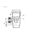
- FIG. 7 is a diagram illustrating an initial position that the visualization device for dust collection of the vacuum cleaner is provided with a foreign material discharge unit which is a main configuration according to the embodiment of the present invention
- FIG. 8 is a diagram illustrating a status where the foreign material discharge unit is pressurized in FIG. 7 .
- the foreign material discharge button 420 shields the foreign material discharge slit 272 and the dust and air may be separated while smoothly accomplishing the cyclonic flow that occurs in the foreign material separation unit 270.
- the end portion of the foreign material discharge button 420 is formed to have the same slope and curvature as the foreign material discharge slit 272 and accordingly the cyclonic flow is accomplished continually not without breaking, by shielding the foreign material discharge slit 272.
- the foreign material discharge button 420 passes the foreign material discharge slit 272 to enter into the inside of the foreign material separation unit 270.
- the foreign material discharge button 420 entered into the inside of the foreign material separation unit 270 as described above crushes the cyclonic flow formed along the internal surface of the foreign material separation unit 270, such that the outdoor air introduced through the by-pass hole 462 may be introduced into the inside of the dust collecting unit 240 through the outdoor air intake unit 422 and the collected dust in the dust collecting unit 240 may be scattered and discharged into the outside of the dust collecting unit 240.
- the foreign material discharge button 420 In the status, when the external pressure applied to the foreign material discharge button 420 is released, the foreign material discharge button 420 is returned to the initial position by the elastic member 440 and the outdoor air intake unit 422 is shielded by the dust collecting unit 240. Further, the end portion of the foreign material discharge button 420 shields the foreign material discharge slit 272 and the cyclonic flow is smoothly maintained again such that the dust may be separated.
- the foreign material discharge unit 400 may consist of other types.
- FIG. 9 is a diagram illustrating an initial position that the visualization device for dust collection of the vacuum cleaner is provided with a foreign material discharge unit which is a main configuration according to another embodiment of the present invention and FIG. 10 is a diagram illustrating a status where the foreign material discharge unit is pressurized in FIG. 9 .
- the foreign material discharge unit 400 for discharging the collected dust in the dust collecting unit 240 is provided with a plug 450 formed by the size and shape corresponding to the foreign material discharge slit 272 to shield the foreign material discharge slit 272.
- the foreign material discharge button 420 which performs the same functions as the above embodiment, is provided to the side portion of the dust collecting unit 240 to press the plug 450 by the external pressure and the inside of the dust collecting unit 240 is further provided with the button housing 460 which guides the pressing path of the foreign material discharge button 420.
- the elastic member 440 when releasing the pressure of the foreign material discharge button 420, the elastic member 440 is provided between the button housing 460 and the foreign material discharge button 420 such that the foreign material discharge button 420 may return to the initial position and the one side of the plug 450 is rotatably fixed to the button housing 460 by a hinge 470
- the lower portion of the plug 450 is fixed by the hinge 470 in the lower portion of the button housing 460, and the center portion is connected to the foreign material discharge button 420.
- the upper portion of the plug 450 is rotated to the inside of the foreign material separation unit 270 around the hinge 470.
- the cyclonic flow formed in the inside of the foreign material separation unit 270 is broken by the rotation of the plug 450 as described above, and the dust collected in the dust collecting unit 240 is discharged while the outdoor air is introduced into the inside of the dust collecting unit 240 thorough a path as in the embodiment described above by the movement of the plug 450.
- the foreign material discharge button 420 when the external pressure applied to the foreign material discharge button 420 is released, the foreign material discharge button 420 is returned to the initial position by the elastic member 440 and the plug 450 shields the foreign material discharge slit 272 and the cyclonic flow may be smoothly maintained again.
- the foreign material discharge unit 400 may consist of other types.
- FIG. 11 is a diagram illustrating an initial position that the visualization device for dust collection of the vacuum cleaner is provided with a foreign material discharge unit which is a main configuration according to another embodiment of the present invention and
- FIG. 12 is a diagram illustrating a status where the foreign material discharge unit is rotated in FIG. 11 .
- the foreign material discharge unit 400 includes a plug 450 formed with the size and shape corresponding to the foreign material discharge slit 272 to shield the foreign material discharge slit 272, a foreign material discharge knob 410 rotatably provided to the side portion of the dust collecting unit 240 and connected to the plug 450 to transmit the rotation force to the plug 450, and knob housing 430 provided to the inside of the dust collecting unit 240 to guide a rotation path of the foreign material discharge knob 410.
- the portion of the foreign material discharge knob 410 is outwardly protruded to be rotated by the user' grip and fixed to the center portion of the plug 450 and when rotating after the user' grip, the plug 450 may be rotated together with the foreign material discharge knob 410.
- the foreign material discharge knob 410 is formed with a perforated portion to introduce the outdoor air and the knob housing 430 is also formed with a predetermined size of hole selectively communicated with the perforated portion.
- the hole formed into the knob housing 430 and the hole formed into the foreign material discharge knob 410 according to the rotation of the foreign material discharge knob 410 are communicated each other to guide the outdoor air into the inside of the dust collecting unit 240.
- the plug 450 When the plug 450 is initially mounted, the plug 450 is disposed to have the same slope direction and angle as the internal surface of the foreign material separation unit 270 and is connected with the foreign material discharge knob 410, the one side of the plug 450 shielding the foreign material discharge slit 272 is formed to have the same type as an internal slope and curvature of the foreign material separation unit 270, like the foreign material discharge button 420 (see FIG. 6 ) of the above mentioned embodiment.
- the cyclonic flow of the foreign material separation unit 270 may be smoothly accomplished and the dust may be easily separated.
- the cyclone flow formed in the inside of the foreign material separation unit 270 is crushed and at the same time, the outdoor air is introduced into the internal side of the inside of the dust collecting unit 240 and the dust of the dust collecting unit 240 is discharged outside by passing the foreign material discharge knob 410 and the knob housing 430 through the foreign material discharge slit 272.
- the discharge of dust as above is performed until the foreign material discharge knob 410 is moved to the initial position by the user, and when the foreign material discharge knob 410 is moved to the initial position, the cyclonic flow of the foreign material separation unit 270 is smoothly accomplished while the foreign material discharge slit 272 is again shield.
- the elastic member 440 is further provided between the foreign material discharge knob 410 and the knob housing 430 so that when the applied force is released by the user to rotate the foreign material discharge knob 410, the foreign material discharge knob 410 may return to the initial position by the elastic force at the same time.
- the foreign material discharge knob 410 is further provided with the elastic member connection unit 412 to be connected with elastic member 440, and the elastic member 440 is tensioned and the elastic force is stored according to the increasing rotation to be restored when the force used to take the rotation of the foreign material discharge knob 410 is released.
- the dust collecting unit is provided with a foreign material discharge unit for forcibly discharging collected dust and the foreign material discharge unit crushes cyclonic flow of a foreign material separation unit while introducing outdoor air into the inside of the dust collecting unit through the user' pressure operation or rotation operation. Therefore, dust collected in the dust collecting unit can be effectively discharged.
Description
- The present invention relates to a visualization device for dust collection of a vacuum cleaner for confirming the dust suction status
- Typically, the vacuum cleaner is a device in which dust and the foreign material together with air are sucked by using a suction motor mounted in the inside of the body to filter the sucked dust and the foreign material in the inside of the main body.
- The vacuum cleaner as described above can be mainly classified as a canister type in which a suction nozzle unit is communicated with the main body through a connection tube and an upright type in which the main body is integrally formed with the suction nozzle unit.
- In the vacuum cleaners as classified above, collecting devices of a bag filtering type or a cyclone dust collecting type, which filter dust and the foreign material among sucked air and store the filtered dust and the foreign material, may be used. Further, due to reasons such as ease of use and maintenance costs, the cyclone dust collecting type is mainly employed in recently released, most vacuum cleaners.
- Meanwhile, in a case that the user performs the cleaning process using the vacuum cleaner, when the user checks whether the dust is sucked, confidence in the performance of the vacuum cleaner and the satisfaction of the cleaning process can be improved.
- Thus, in order to meet the needs of the user as described above, there is a need for a visualization device that suction status of dust according to the cleaning process is displayed on the outside.
- A visualization device for dust collection of a vacuum cleaner is known e.g. from
EP-A-1199023 . - An object of the present invention is to provide a visualization device for dust collection of a vacuum cleaner in which some of sucked dust during the cleaning process is exposed to the outside and accordingly the user directly confirms suction status of dust.
- Another object of the present invention is to provide a visualization device for dust collection of a vacuum cleaner in which collected dust is effectively discharged in order to visualize the dust suction status.
- According to the prevent invention, the visualization device for dust collection of a vacuum cleaner, comprising a collecting unit mounted on one side of a pathway on which the suction force of a vacuum cleaner for sucking dust is transmitted, and moves at least some of the sucked dust in one direction, a dust collecting unit, which is transparent material, coupled with the collecting unit and exposes a state of dust received by the collecting unit to the outside, a discharge unit which guides air and dust, which has passed through the dust collecting unit, to be discharged into the pathway that transmits the suction force of the vacuum cleaner, a foreign material separation unit provided in the dust collecting unit to generate cyclonic flow, and a foreign material discharge unit inserted into the inside of the foreign material separation unit by the manipulation of a user from one side of the dust collecting unit and allows the inflow of air from the outside into the inside thereof to discharge dust from the inside of the dust collecting unit while breaking the cyclonic flow.
-
-
FIG. 1 is a diagram illustrating an appearance of a vacuum cleaner of an embodiment employed in the present invention. -
FIG. 2 is a diagram illustrating a status where a visualization device for dust collection of the vacuum cleaner is mounted on one side of a suction nozzle according to the embodiment of the present invention. -
FIGS. 3 and4 are diagrams illustrating configurations that the visualization device for dust collection of the vacuum cleaner is mounted according to the embodiment of the present invention. -
FIG. 5 is a diagram illustrating an appearance of the visualization device for dust collection of the vacuum cleaner according to the embodiment of the present invention. -
FIG. 6 is a cross sectional view taken along A-A ofFIG. 5 . -
FIG. 7 is a diagram illustrating an initial position that the visualization device for dust collection of the vacuum cleaner is provided with a foreign material discharge unit which is a main configuration according to the embodiment of the present invention. -
FIG. 8 is a diagram illustrating a status where the foreign material discharge unit is pressurized inFIG. 7 . -
FIG. 9 is a diagram illustrating an initial position that a visualization device for dust collection of a vacuum cleaner is provided with a foreign material discharge unit which is a main configuration according to another embodiment of the present invention. -
FIG. 10 is a diagram illustrating a status where the foreign material discharge unit inFIG. 9 is pressurized. -
FIG. 11 is a diagram illustrating an initial position that a visualization device for dust collection of a vacuum cleaner is provided with a foreign material discharge unit which is a main configuration according to another embodiment of the present invention. -
FIG. 12 is a diagram illustrating a status where the foreign material discharge unit inFIG. 11 is rotated. - Hereinafter, embodiments of the present invention will be concretely described with reference to drawings. The present invention is not limited to embodiments as proposed and various modified embodiments can be available by those skilled in the art without the scope of the present invention. In addition, these modified embodiments should not be appreciated separately from technical spirits or prospects.
-
FIG. 1 is a diagram illustrating an appearance of a vacuum cleaner of a embodiment employed in the present invention,FIG. 2 is a diagram illustrating a status where a visualization device for dust collection of the vacuum cleaner is mounted on one side of a suction nozzle according to the embodiment of the present invention, andFIGS. 3 and4 are diagrams illustrating configurations that the visualization device for dust collection of the vacuum cleaner is mounted according to the embodiment of the present invention. - As shown in the drawings, the vacuum cleaner employed in the present invention includes a main body 1 which generates a suction force by using a suction motor, a
connection unit 20 which transmits the generated suction force in the main body 1, and asuction nozzle 100 which is provided to one side of theconnection unit 20 to suck water scattered on a surface to be cleaned with air. - The
connection unit 20 may include a lengthadjustable extension pipe 22 on which thesuction nozzle 100 is mounted to the one end, and aconnection pipe 24 of flexible material connecting theextension pipe 22 to the main body 1 - The
suction nozzle 100 is formed into an appearance by acase 120 and thecase 120 is formed by theupper case 124 and thelower case 122 connected each other. - In addition, the
upper case 124 and the rear end of thelower case 122 are provided with aconnection unit 140 having the diameter corresponding to the diameter of theextension pipe 22 to be fittingly mounted on theextension pipe 22. - Meanwhile, the one side of the
case 120 is provided with thevisualization device 200 of dust collection for outside visualizing the collection status of the foreign material on the one side of the pathway of the suction force generated from the main body 1. - According to the one embodiment of the present invention, the
visualization device 200 of dust collection is intended to receive air collected through thesuction nozzle 100 and a portion of dust included in the air and to show the receiving status of the dust on the outside. Accordingly, thevisualization device 200 is located on the front of theconnection unit 140 to shield a portion of flow path of air moved to the main body 1 - Therefore, a portion of air moved to the main body 1 may be introduced into the
visualization device 200 of dust collection. - Meanwhile, the
suction nozzle 100 is fittingly mounted to theextension pipe 22 to clean bedding such as covers or mattress or knitted goods having down and fluff such as blanket or carpeting and includes aturbine 160 which generates vibration to the inside of thecase 120 and avibration frame 180 which generates vibration by rotating theturbine 160. - In addition, the
upper case 124 is provided with anair intake hole 123 which introduces the outdoor air into the position corresponding to the mounted position of theturbine 160 to smoothly rotate theturbine 160. - Accordingly, the
turbine 160 rotates by using air introduced into theair intake hole 123 with air introduced into suction port (not shown) formed on the lower of thesuction nozzle 100. - In addition, since the
turbine 160 and thevibration frame 180 are connected by using an eccentric cam each other, when theturbine 160 rotates, thevibration frame 180 connected to theturbine 160 is vibrated. - In addition, since the
turbine 160 is disposed to the position of the front of thevisualization device 200 of dust collection, air forced for flow by theturbine 160 and dust included in the air may be easily introduced into the inside of thevisualization device 200 of dust collection. - Meanwhile, according to the embodiment of the present invention, the
visualization device 200 of dust collection is largely configured to include thecollecting unit 220 which guides air sucked through thesuction nozzle 100 and dust introduced into the inside and the dust collectingunit 240 which collects dust introduced through thecollecting unit 220 and outside exposes the collected dust. - The
collecting unit 220 is formed by a cylindrical shape that the upper side is opened and the edge of the upper end is provided with thecase 120 to maintain the fixed position. Further, thecollecting unit 220 may include a mounting protrusion (not shown) formed by outwardly protruding so as to not leak air and dust sucked in thecase 120 into the mounting portion of thevisualization device 200 of dust collection. - In particular, the external surface of the
collecting unit 220, which is protruded for the portion forward the mounting location of theturbine 160, and the protruded portion is formed with thesuction inlet 222 that air and dust may be introduced into thecollecting unit 220. - The
suction inlet 222 is formed to guide the flow of air into a tangential direction of the inside of thecollecting unit 220, and air introduced inside thecollecting unit 220 is moved while rotating along the inner surface. - The upper side of the
collecting unit 220 is mounted with thedust collecting unit 240 in which air transferred while rotating and dust through thesuction inlet 222 included in the air are received. - The
dust collecting unit 240 is formed by the transparent material which may be exposed to the outside of the dust reception status and the inside of thedust collecting unit 240 is further provided with a foreignmaterial separation unit 270 which generates a cyclonic flow to separate dust and air. - In addition, the side portion of the
dust collecting unit 240 is further provided with the foreignmaterial discharge unit 400 which crushes the cyclonic flow of the foreignmaterial separation unit 270 while introducing the outdoor air into the inside to discharge air collected in the inside of thedust collecting unit 240. - The dust discharged to the outside by the foreign
material discharge unit 400 may be discharged through adischarge unit 260 communicated with thedust collecting unit 240. - Meanwhile,
FIG. 5 is a diagram illustrating an appearance of the visualization device for dust collection of the vacuum cleaner according to an embodiment of the present invention, andFIG. 6 is a cross sectional view taken along A-A ofFIG. 5 . - Referring to the drawings, the foreign
material separation unit 270 is lengthily formed with a foreignmaterial discharge slit 272 in the lateral direction of the side portion. - In addition, the foreign
material discharge slit 272 formed as described above is provided with a end portion of a foreignmaterial discharge button 420 which is a configuration of the foreignmaterial discharge unit 400 to maintain the same plane as the inside surface of the foreignmaterial separation unit 270. In such a state, the cyclonic flow formed by the foreignmaterial separation unit 270 may be smoothly accomplished. - The foreign
material discharge unit 400 includes the foreignmaterial discharge button 420 as described above, abutton housing 460 which receives one side of the foreignmaterial discharge button 420 to press the foreignmaterial discharge button 420 by the external pressure and to guide to slidingly be moved the inside of thedust collecting unit 240, and anelastic member 440 included between the foreignmaterial discharge button 420 and thebutton housing 460. - In detail, the upper portion of the foreign
material discharge button 420 has the upper surface of flat-panel form to allow the user to facilitate the pressurization, and the lower side is formed by a narrower width than width of the upper potion to penetrate the one side of thedust collecting unit 240. - To this end, the side portion of the
dust collecting unit 240 is formed with a perforated portion by a size corresponding to the foreignmaterial discharge button 420 and the perforated portion is mounded with thebutton housing 460. - Accordingly, the
button housing 460 is formed to correspond to perforated portion of thedust collecting unit 240 and the center portion is corresponded to the diameter and shape of the foreignmaterial discharge button 420 so that the foreignmaterial discharge button 420 may be passed. - In addition, the upper portion of the
button housing 460 is provided with achin rest 464 outwardly protruded by the predetermined length such that thechin rest 464 and the upper inside of the foreignmaterial discharge button 420 are interfered each other and, theelastic member 440 are provided between thechin rest 464 and the upper inside of the foreignmaterial discharge button 420 each other interfered as described above. - Meanwhile, the side portion of the
button housing 460 is formed with a perforated portion and a by-pass hole 462 to introduce the outdoor air and the external surface of the foreignmaterial discharge button 420 is further formed with an outdoorair intake unit 422 on which a recessed portion is formed in the inside side. - Herein, the outdoor
air intake unit 422 is not formed from the lower end of the foreignmaterial discharge button 420 to thedust collecting unit 240, but formed from exposed portion from the outside of the side portion of thedust collecting unit 240 to the upper side, such that the outdoor air introduced through the by-pass hole 462 is not introduced into the inside of thedust collecting unit 240 at the initial position of the foreign material discharge button 420 (seeFIG. 6 ). - For a more detailed description,
FIG. 7 is a diagram illustrating an initial position that the visualization device for dust collection of the vacuum cleaner is provided with a foreign material discharge unit which is a main configuration according to the embodiment of the present invention andFIG. 8 is a diagram illustrating a status where the foreign material discharge unit is pressurized inFIG. 7 . - Referring to the drawings, as shown in
FIG. 7 , when the foreignmaterial discharge unit 400 maintains the initial mounting position, the foreignmaterial discharge button 420 shields the foreign material discharge slit 272 and the dust and air may be separated while smoothly accomplishing the cyclonic flow that occurs in the foreignmaterial separation unit 270. - That is, the end portion of the foreign
material discharge button 420 is formed to have the same slope and curvature as the foreign material discharge slit 272 and accordingly the cyclonic flow is accomplished continually not without breaking, by shielding the foreign material discharge slit 272. - Meanwhile, in the status as described above, when the user presses the foreign
material discharge button 420, as shown inFIG. 8 , the foreignmaterial discharge button 420 passes the foreign material discharge slit 272 to enter into the inside of the foreignmaterial separation unit 270. - Accordingly, the foreign
material discharge button 420 entered into the inside of the foreignmaterial separation unit 270 as described above crushes the cyclonic flow formed along the internal surface of the foreignmaterial separation unit 270, such that the outdoor air introduced through the by-pass hole 462 may be introduced into the inside of thedust collecting unit 240 through the outdoorair intake unit 422 and the collected dust in thedust collecting unit 240 may be scattered and discharged into the outside of thedust collecting unit 240. - In the status, when the external pressure applied to the foreign
material discharge button 420 is released, the foreignmaterial discharge button 420 is returned to the initial position by theelastic member 440 and the outdoorair intake unit 422 is shielded by thedust collecting unit 240. Further, the end portion of the foreignmaterial discharge button 420 shields the foreign material discharge slit 272 and the cyclonic flow is smoothly maintained again such that the dust may be separated. - Meanwhile, in another embodiment of the present invention, the foreign
material discharge unit 400 may consist of other types. -
FIG. 9 is a diagram illustrating an initial position that the visualization device for dust collection of the vacuum cleaner is provided with a foreign material discharge unit which is a main configuration according to another embodiment of the present invention andFIG. 10 is a diagram illustrating a status where the foreign material discharge unit is pressurized inFIG. 9 . - As shown in the drawings, in another embodiment of the present invention, the foreign
material discharge unit 400 for discharging the collected dust in thedust collecting unit 240 is provided with aplug 450 formed by the size and shape corresponding to the foreign material discharge slit 272 to shield the foreign material discharge slit 272. - In addition, the foreign
material discharge button 420, which performs the same functions as the above embodiment, is provided to the side portion of thedust collecting unit 240 to press theplug 450 by the external pressure and the inside of thedust collecting unit 240 is further provided with thebutton housing 460 which guides the pressing path of the foreignmaterial discharge button 420. - Further, as mentioned embodiments, when releasing the pressure of the foreign
material discharge button 420, theelastic member 440 is provided between thebutton housing 460 and the foreignmaterial discharge button 420 such that the foreignmaterial discharge button 420 may return to the initial position and the one side of theplug 450 is rotatably fixed to thebutton housing 460 by ahinge 470 - In detail, the lower portion of the
plug 450 is fixed by thehinge 470 in the lower portion of thebutton housing 460, and the center portion is connected to the foreignmaterial discharge button 420. In this case, when the foreignmaterial discharge button 420 is pressurized, the upper portion of theplug 450 is rotated to the inside of the foreignmaterial separation unit 270 around thehinge 470. - Therefore, the cyclonic flow formed in the inside of the foreign
material separation unit 270 is broken by the rotation of theplug 450 as described above, and the dust collected in thedust collecting unit 240 is discharged while the outdoor air is introduced into the inside of thedust collecting unit 240 thorough a path as in the embodiment described above by the movement of theplug 450. - In addition, in another embodiment of the present invention, when the external pressure applied to the foreign
material discharge button 420 is released, the foreignmaterial discharge button 420 is returned to the initial position by theelastic member 440 and theplug 450 shields the foreign material discharge slit 272 and the cyclonic flow may be smoothly maintained again. - Meanwhile, in another embodiment of the present invention, the foreign
material discharge unit 400 may consist of other types. -
FIG. 11 is a diagram illustrating an initial position that the visualization device for dust collection of the vacuum cleaner is provided with a foreign material discharge unit which is a main configuration according to another embodiment of the present invention andFIG. 12 is a diagram illustrating a status where the foreign material discharge unit is rotated inFIG. 11 . - As shown in the drawings, in another embodiment of the present invention the foreign
material discharge unit 400 includes aplug 450 formed with the size and shape corresponding to the foreign material discharge slit 272 to shield the foreign material discharge slit 272, a foreignmaterial discharge knob 410 rotatably provided to the side portion of thedust collecting unit 240 and connected to theplug 450 to transmit the rotation force to theplug 450, andknob housing 430 provided to the inside of thedust collecting unit 240 to guide a rotation path of the foreignmaterial discharge knob 410. - In detail, the portion of the foreign
material discharge knob 410 is outwardly protruded to be rotated by the user' grip and fixed to the center portion of theplug 450 and when rotating after the user' grip, theplug 450 may be rotated together with the foreignmaterial discharge knob 410. - In addition, although not shown in the drawings, the foreign
material discharge knob 410 is formed with a perforated portion to introduce the outdoor air and theknob housing 430 is also formed with a predetermined size of hole selectively communicated with the perforated portion. - Accordingly, the hole formed into the
knob housing 430 and the hole formed into the foreignmaterial discharge knob 410 according to the rotation of the foreignmaterial discharge knob 410 are communicated each other to guide the outdoor air into the inside of thedust collecting unit 240. - When the
plug 450 is initially mounted, theplug 450 is disposed to have the same slope direction and angle as the internal surface of the foreignmaterial separation unit 270 and is connected with the foreignmaterial discharge knob 410, the one side of theplug 450 shielding the foreign material discharge slit 272 is formed to have the same type as an internal slope and curvature of the foreignmaterial separation unit 270, like the foreign material discharge button 420 (seeFIG. 6 ) of the above mentioned embodiment. - Accordingly, in such a state, the cyclonic flow of the foreign
material separation unit 270 may be smoothly accomplished and the dust may be easily separated. - Meanwhile, in the status, when the foreign
material discharge knob 410 is rotated by the user' grip, as shown inFIG. 12 , the slope direction of theplug 450 is changed while theplug 450 is rotated so that the portion of theplug 450 may be entered into the inside of the foreignmaterial separation unit 270. - As a result, the cyclone flow formed in the inside of the foreign
material separation unit 270 is crushed and at the same time, the outdoor air is introduced into the internal side of the inside of thedust collecting unit 240 and the dust of thedust collecting unit 240 is discharged outside by passing the foreignmaterial discharge knob 410 and theknob housing 430 through the foreign material discharge slit 272. - The discharge of dust as above is performed until the foreign
material discharge knob 410 is moved to the initial position by the user, and when the foreignmaterial discharge knob 410 is moved to the initial position, the cyclonic flow of the foreignmaterial separation unit 270 is smoothly accomplished while the foreign material discharge slit 272 is again shield. - Meanwhile, the
elastic member 440 is further provided between the foreignmaterial discharge knob 410 and theknob housing 430 so that when the applied force is released by the user to rotate the foreignmaterial discharge knob 410, the foreignmaterial discharge knob 410 may return to the initial position by the elastic force at the same time. - To this end, the foreign
material discharge knob 410 is further provided with the elastic member connection unit 412 to be connected withelastic member 440, and theelastic member 440 is tensioned and the elastic force is stored according to the increasing rotation to be restored when the force used to take the rotation of the foreignmaterial discharge knob 410 is released. - In the present invention, since a suction status of dust is exposed to the outside of the dust collecting unit, the user can easily confirm the dust suction status.
- In addition, the dust collecting unit is provided with a foreign material discharge unit for forcibly discharging collected dust and the foreign material discharge unit crushes cyclonic flow of a foreign material separation unit while introducing outdoor air into the inside of the dust collecting unit through the user' pressure operation or rotation operation. Therefore, dust collected in the dust collecting unit can be effectively discharged.
- Although preferred embodiments of the present invention have been illustrated and described, the present invention is not limited to the above-mentioned embodiments and various modified embodiments can be available by those skilled in the art without the scope of the appended claims of the present invention. In addition, these modified embodiments should not be appreciated separately from technical spirits or prospects.
Claims (11)
- A visualization device (200) for dust collection of a vacuum cleaner, comprising:a collecting unit (220) mounted on one side of a pathway on which the suction force of a vacuum cleaner for sucking dust is transmitted to move at least some of the sucked dust in one direction;a dust collecting unit (240) coupled with the collecting unit (220) and exposes a state of dust received by the collecting unit to the outside;a discharge unit (260) which guides air and dust, which has passed through the dust collecting unit (240), to be discharged into the pathway that transmits the suction force of the vacuum cleaner;a foreign material separation unit (270) provided in the dust collecting unit (240) to generate cyclonic flow; anda foreign material discharge unit (400) inserted into the inside of the foreign material separation unit (270) by the manipulation of a user from one side of the dust collecting unit (240) and allows the inflow of air from the outside into the inside of the dust collecting unit (240) to discharge dust from the inside of the dust collecting unit (240) while breaking the cyclonic flow.
- The visualization device (200) according to the Claim 1, the foreign material separation unit (270) is formed with a foreign material discharge slit (272) which is selectively opened and closed by the foreign material discharge unit (400).
- The visualization device (200) according to the Claim 2, wherein the foreign material discharge unit (400) includes:a foreign material discharge button (420) provided on the side of the dust collecting unit (240) to selectively shield the foreign material discharge slit (272) while slidingly moving in the inside of the dust collecting unit (240) by external pressure;a button housing (460) which guides a sliding movement of the foreign material discharge button (420); andan elastic member (440) for returning the foreign material discharge button (420) to the initial position when releasing the pressure of the foreign material discharge button (420).
- The visualization device (200) according to the Claim 3, wherein the end portion of the foreign material discharge button (420) is formed as the size and shape corresponding to the foreign material discharge slit (272) and forms the same plane as the inner surface of the foreign material separation unit (270) to prevent the cyclonic flow from crushing in a state where the end portion is inserted into the foreign material discharge slit (272).
- The visualization device (200) according to the Claim 3, wherein the button housing (460) is provided with a by-pass hole (462) to introduce an outdoor air into the inside of the dust collecting unit (240) and the foreign material discharge button (420) is formed with an outdoor air intake unit (422) communicated with the by-pass hole (420) when pressing to introduce the outdoor air into the inside of the dust collecting unit (240).
- The visualization device (200) according to the Claim 2, wherein the foreign material discharge unit (400) includes:a plug (450) formed in the size and shape corresponding to the foreign material discharge slit (272) to shield the foreign material discharge slit (272);a foreign material discharge button (420) provided to the side portion of the dust collecting unit (240) to insert one side of the plug (450) into the inside of the foreign material discharge slit (272) by pressing the plug (450) according to the external pressure;a button housing (460) provided to the inside of the dust collecting unit (240) to guide a pressure path of the foreign material discharge button (420);an elastic member (440) provided between the button housing (460) and the foreign material discharge button (420) to return the foreign material discharge button (420) to the initial position when releasing the pressure of the foreign material discharge button (420); anda hinge (470) rotatably fixing the one side of the plug to the button housing (460).
- The visualization device (200) according to the Claim 6, wherein the one side of the plug (450) is provided in the same plane as the inner surface of the foreign material separation unit (270) at the initial position to prevent the cyclonic flow from crushing.
- The visualization device (200) according to the Claim 2, wherein the foreign material discharge unit (400) includes:a plug (450) formed with the size and shape corresponding to the foreign material discharge slit (272) to shield the foreign material discharge slit (272);a foreign material discharge knob (410) rotatably provided to the side portion of the dust collecting unit (240) and connected to the plug (450) to transmit the rotation force to the plug (450);a knob housing (430) provided to the inside of the dust collecting unit (240) to guide a rotation path of the foreign material discharge knob (410).
- The visualization device (200) according to the Claim 8, wherein the plug (450) is connected to the foreign material discharge knob (410) and forms the initial position to have the same slope direction as the external slop angle of the foreign material discharge unit (400).
- The visualization device (200) according to the Claim 9, wherein in the plug (450), one side of the plug (450) is inserted into the inside of the foreign material discharge unit (400) while changing the slope direction when rotating of the foreign material discharge knob (410) to crush the cyclonic flow.
- The visualization device (200) according to the Claim 8, further including an elastic member (440) between the foreign material discharge knob (410) and the knob housing (430) for returning the foreign material discharge knob (410) to the initial position by elasticity.
Applications Claiming Priority (1)
| Application Number | Priority Date | Filing Date | Title |
|---|---|---|---|
| PCT/KR2009/006459 WO2011055866A1 (en) | 2009-11-04 | 2009-11-04 | Visualization device for dust collection of vacuum cleaner |
Publications (3)
| Publication Number | Publication Date |
|---|---|
| EP2417885A1 EP2417885A1 (en) | 2012-02-15 |
| EP2417885A4 EP2417885A4 (en) | 2013-04-24 |
| EP2417885B1 true EP2417885B1 (en) | 2015-01-21 |
Family
ID=43970096
Family Applications (1)
| Application Number | Title | Priority Date | Filing Date |
|---|---|---|---|
| EP09851122.3A Not-in-force EP2417885B1 (en) | 2009-11-04 | 2009-11-04 | Visualization device for dust collection of vacuum cleaner |
Country Status (4)
| Country | Link |
|---|---|
| US (1) | US8549700B2 (en) |
| EP (1) | EP2417885B1 (en) |
| AU (1) | AU2009355000B2 (en) |
| WO (1) | WO2011055866A1 (en) |
Family Cites Families (14)
| Publication number | Priority date | Publication date | Assignee | Title |
|---|---|---|---|---|
| SE395355B (en) * | 1975-12-05 | 1977-08-15 | Electrolux Ab | VACUUM CLEANER INDICATOR DEVICE |
| DE3513484A1 (en) * | 1985-04-16 | 1986-10-16 | Krupp Polysius Ag, 4720 Beckum | METHOD FOR REDUCING NITROGEN EMISSION FROM CEMENT PLANTING PLANTS |
| JP3476066B2 (en) * | 1999-07-19 | 2003-12-10 | シャープ株式会社 | Electric vacuum cleaner |
| JP2003204904A (en) | 2001-11-09 | 2003-07-22 | Sharp Corp | Vacuum cleaner |
| JP2004057445A (en) | 2002-07-29 | 2004-02-26 | Matsushita Electric Ind Co Ltd | Vacuum cleaner |
| JP2004267236A (en) * | 2003-03-05 | 2004-09-30 | Hitachi Ltd | Self-traveling type vacuum cleaner and charging device used for the same |
| DE102004007677B4 (en) * | 2004-02-16 | 2011-11-17 | Miele & Cie. Kg | Suction nozzle for a vacuum cleaner with a dust flow indicator |
| KR100697429B1 (en) | 2004-12-27 | 2007-03-20 | 엘지전자 주식회사 | Vacuum cleaner |
| EP1871210B1 (en) * | 2005-03-03 | 2012-05-16 | Nilfisk-Advance A/S | A method of determining the degree of filling of the dust collector of a vacuum cleaner and a filling indicator |
| JP4321511B2 (en) | 2005-10-25 | 2009-08-26 | パナソニック株式会社 | Electric vacuum cleaner |
| JP4212608B2 (en) | 2006-06-14 | 2009-01-21 | 株式会社東芝 | Electric vacuum cleaner |
| JP4342540B2 (en) | 2006-08-09 | 2009-10-14 | 株式会社東芝 | Electric vacuum cleaner |
| US8172932B2 (en) * | 2007-04-11 | 2012-05-08 | Samsung Electronics Co., Ltd. | Connecting tube having dust sensing function for use in vacuum cleaner |
| KR20080092063A (en) * | 2007-04-11 | 2008-10-15 | 삼성광주전자 주식회사 | Dust sensing unit for use in a vacuum cleaner |
-
2009
- 2009-11-04 AU AU2009355000A patent/AU2009355000B2/en not_active Ceased
- 2009-11-04 EP EP09851122.3A patent/EP2417885B1/en not_active Not-in-force
- 2009-11-04 WO PCT/KR2009/006459 patent/WO2011055866A1/en active Application Filing
- 2009-11-04 US US13/378,641 patent/US8549700B2/en not_active Expired - Fee Related
Also Published As
| Publication number | Publication date |
|---|---|
| EP2417885A4 (en) | 2013-04-24 |
| AU2009355000A1 (en) | 2011-11-24 |
| US20120090128A1 (en) | 2012-04-19 |
| US8549700B2 (en) | 2013-10-08 |
| WO2011055866A1 (en) | 2011-05-12 |
| EP2417885A1 (en) | 2012-02-15 |
| AU2009355000B2 (en) | 2013-09-12 |
Similar Documents
| Publication | Publication Date | Title |
|---|---|---|
| US11910992B2 (en) | Handheld vacuum cleaner | |
| US20200178744A1 (en) | Vacuum cleaner | |
| CN107072453B (en) | Hand-held vacuum cleaner | |
| US6192550B1 (en) | Dust-collecting device for vacuum cleaner and upright type vacuum cleaner | |
| CA2448117C (en) | Filter cleaning device of cyclone vacuum cleaner | |
| CN110430795A (en) | Hand-held vacuum cleaner | |
| CN112568782B (en) | Double-effect ash scraping cleaning device and ash scraping method | |
| JP2008000379A (en) | Vacuum cleaner | |
| CN215502724U (en) | Cleaning device | |
| CN112656291B (en) | Cleaning device | |
| EP2422673B1 (en) | Visualization device for dust collection of vacuum cleaner | |
| JP3667219B2 (en) | Vacuum cleaner | |
| JP2011131013A (en) | Dust collection tank for vacuum cleaner | |
| JP2011131014A (en) | Vacuum cleaner and dust collection tank for vacuum cleaner | |
| EP2417885B1 (en) | Visualization device for dust collection of vacuum cleaner | |
| CN104254272A (en) | Dust-collecting device and electric vacuum cleaner equipped with dust collecting device | |
| EP1902656A1 (en) | Vacuum cleaner having mounting position-changeable noise absorbing apparatus | |
| CN112587029B (en) | Dust collector host and dust collector | |
| JP2007117465A (en) | Dust collector and vacuum cleaner having the same | |
| JP4267041B2 (en) | Electric vacuum cleaner | |
| JP2005177289A (en) | Vacuum cleaner | |
| CN217285626U (en) | Display screen assembly and cleaning device | |
| CN215305439U (en) | Cleaning device for ash is scraped to economic benefits and social benefits | |
| JP2009131676A (en) | Vacuum cleaner | |
| JP2007029332A (en) | Electric cleaner |
Legal Events
| Date | Code | Title | Description |
|---|---|---|---|
| PUAI | Public reference made under article 153(3) epc to a published international application that has entered the european phase |
Free format text: ORIGINAL CODE: 0009012 |
|
| 17P | Request for examination filed |
Effective date: 20111109 |
|
| AK | Designated contracting states |
Kind code of ref document: A1 Designated state(s): AT BE BG CH CY CZ DE DK EE ES FI FR GB GR HR HU IE IS IT LI LT LU LV MC MK MT NL NO PL PT RO SE SI SK SM TR |
|
| DAX | Request for extension of the european patent (deleted) | ||
| A4 | Supplementary search report drawn up and despatched |
Effective date: 20130322 |
|
| RIC1 | Information provided on ipc code assigned before grant |
Ipc: A47L 9/16 20060101ALI20130318BHEP Ipc: A47L 9/10 20060101AFI20130318BHEP |
|
| GRAP | Despatch of communication of intention to grant a patent |
Free format text: ORIGINAL CODE: EPIDOSNIGR1 |
|
| INTG | Intention to grant announced |
Effective date: 20140926 |
|
| GRAS | Grant fee paid |
Free format text: ORIGINAL CODE: EPIDOSNIGR3 |
|
| GRAA | (expected) grant |
Free format text: ORIGINAL CODE: 0009210 |
|
| AK | Designated contracting states |
Kind code of ref document: B1 Designated state(s): AT BE BG CH CY CZ DE DK EE ES FI FR GB GR HR HU IE IS IT LI LT LU LV MC MK MT NL NO PL PT RO SE SI SK SM TR |
|
| REG | Reference to a national code |
Ref country code: GB Ref legal event code: FG4D |
|
| REG | Reference to a national code |
Ref country code: CH Ref legal event code: EP |
|
| REG | Reference to a national code |
Ref country code: IE Ref legal event code: FG4D |
|
| REG | Reference to a national code |
Ref country code: DE Ref legal event code: R096 Ref document number: 602009029178 Country of ref document: DE Effective date: 20150305 |
|
| REG | Reference to a national code |
Ref country code: AT Ref legal event code: REF Ref document number: 708779 Country of ref document: AT Kind code of ref document: T Effective date: 20150315 |
|
| REG | Reference to a national code |
Ref country code: NL Ref legal event code: VDEP Effective date: 20150121 |
|
| REG | Reference to a national code |
Ref country code: AT Ref legal event code: MK05 Ref document number: 708779 Country of ref document: AT Kind code of ref document: T Effective date: 20150121 |
|
| REG | Reference to a national code |
Ref country code: LT Ref legal event code: MG4D |
|
| PG25 | Lapsed in a contracting state [announced via postgrant information from national office to epo] |
Ref country code: FI Free format text: LAPSE BECAUSE OF FAILURE TO SUBMIT A TRANSLATION OF THE DESCRIPTION OR TO PAY THE FEE WITHIN THE PRESCRIBED TIME-LIMIT Effective date: 20150121 Ref country code: SE Free format text: LAPSE BECAUSE OF FAILURE TO SUBMIT A TRANSLATION OF THE DESCRIPTION OR TO PAY THE FEE WITHIN THE PRESCRIBED TIME-LIMIT Effective date: 20150121 Ref country code: BG Free format text: LAPSE BECAUSE OF FAILURE TO SUBMIT A TRANSLATION OF THE DESCRIPTION OR TO PAY THE FEE WITHIN THE PRESCRIBED TIME-LIMIT Effective date: 20150421 Ref country code: HR Free format text: LAPSE BECAUSE OF FAILURE TO SUBMIT A TRANSLATION OF THE DESCRIPTION OR TO PAY THE FEE WITHIN THE PRESCRIBED TIME-LIMIT Effective date: 20150121 Ref country code: ES Free format text: LAPSE BECAUSE OF FAILURE TO SUBMIT A TRANSLATION OF THE DESCRIPTION OR TO PAY THE FEE WITHIN THE PRESCRIBED TIME-LIMIT Effective date: 20150121 Ref country code: NO Free format text: LAPSE BECAUSE OF FAILURE TO SUBMIT A TRANSLATION OF THE DESCRIPTION OR TO PAY THE FEE WITHIN THE PRESCRIBED TIME-LIMIT Effective date: 20150421 Ref country code: LT Free format text: LAPSE BECAUSE OF FAILURE TO SUBMIT A TRANSLATION OF THE DESCRIPTION OR TO PAY THE FEE WITHIN THE PRESCRIBED TIME-LIMIT Effective date: 20150121 |
|
| PG25 | Lapsed in a contracting state [announced via postgrant information from national office to epo] |
Ref country code: IS Free format text: LAPSE BECAUSE OF FAILURE TO SUBMIT A TRANSLATION OF THE DESCRIPTION OR TO PAY THE FEE WITHIN THE PRESCRIBED TIME-LIMIT Effective date: 20150521 Ref country code: NL Free format text: LAPSE BECAUSE OF FAILURE TO SUBMIT A TRANSLATION OF THE DESCRIPTION OR TO PAY THE FEE WITHIN THE PRESCRIBED TIME-LIMIT Effective date: 20150121 Ref country code: AT Free format text: LAPSE BECAUSE OF FAILURE TO SUBMIT A TRANSLATION OF THE DESCRIPTION OR TO PAY THE FEE WITHIN THE PRESCRIBED TIME-LIMIT Effective date: 20150121 Ref country code: PL Free format text: LAPSE BECAUSE OF FAILURE TO SUBMIT A TRANSLATION OF THE DESCRIPTION OR TO PAY THE FEE WITHIN THE PRESCRIBED TIME-LIMIT Effective date: 20150121 Ref country code: LV Free format text: LAPSE BECAUSE OF FAILURE TO SUBMIT A TRANSLATION OF THE DESCRIPTION OR TO PAY THE FEE WITHIN THE PRESCRIBED TIME-LIMIT Effective date: 20150121 Ref country code: GR Free format text: LAPSE BECAUSE OF FAILURE TO SUBMIT A TRANSLATION OF THE DESCRIPTION OR TO PAY THE FEE WITHIN THE PRESCRIBED TIME-LIMIT Effective date: 20150422 |
|
| REG | Reference to a national code |
Ref country code: DE Ref legal event code: R097 Ref document number: 602009029178 Country of ref document: DE |
|
| REG | Reference to a national code |
Ref country code: FR Ref legal event code: PLFP Year of fee payment: 7 |
|
| PG25 | Lapsed in a contracting state [announced via postgrant information from national office to epo] |
Ref country code: SK Free format text: LAPSE BECAUSE OF FAILURE TO SUBMIT A TRANSLATION OF THE DESCRIPTION OR TO PAY THE FEE WITHIN THE PRESCRIBED TIME-LIMIT Effective date: 20150121 Ref country code: CZ Free format text: LAPSE BECAUSE OF FAILURE TO SUBMIT A TRANSLATION OF THE DESCRIPTION OR TO PAY THE FEE WITHIN THE PRESCRIBED TIME-LIMIT Effective date: 20150121 Ref country code: DK Free format text: LAPSE BECAUSE OF FAILURE TO SUBMIT A TRANSLATION OF THE DESCRIPTION OR TO PAY THE FEE WITHIN THE PRESCRIBED TIME-LIMIT Effective date: 20150121 Ref country code: RO Free format text: LAPSE BECAUSE OF FAILURE TO SUBMIT A TRANSLATION OF THE DESCRIPTION OR TO PAY THE FEE WITHIN THE PRESCRIBED TIME-LIMIT Effective date: 20150121 Ref country code: EE Free format text: LAPSE BECAUSE OF FAILURE TO SUBMIT A TRANSLATION OF THE DESCRIPTION OR TO PAY THE FEE WITHIN THE PRESCRIBED TIME-LIMIT Effective date: 20150121 |
|
| PLBE | No opposition filed within time limit |
Free format text: ORIGINAL CODE: 0009261 |
|
| STAA | Information on the status of an ep patent application or granted ep patent |
Free format text: STATUS: NO OPPOSITION FILED WITHIN TIME LIMIT |
|
| 26N | No opposition filed |
Effective date: 20151022 |
|
| PG25 | Lapsed in a contracting state [announced via postgrant information from national office to epo] |
Ref country code: IT Free format text: LAPSE BECAUSE OF FAILURE TO SUBMIT A TRANSLATION OF THE DESCRIPTION OR TO PAY THE FEE WITHIN THE PRESCRIBED TIME-LIMIT Effective date: 20150121 |
|
| PG25 | Lapsed in a contracting state [announced via postgrant information from national office to epo] |
Ref country code: SI Free format text: LAPSE BECAUSE OF FAILURE TO SUBMIT A TRANSLATION OF THE DESCRIPTION OR TO PAY THE FEE WITHIN THE PRESCRIBED TIME-LIMIT Effective date: 20150121 |
|
| PG25 | Lapsed in a contracting state [announced via postgrant information from national office to epo] |
Ref country code: BE Free format text: LAPSE BECAUSE OF FAILURE TO SUBMIT A TRANSLATION OF THE DESCRIPTION OR TO PAY THE FEE WITHIN THE PRESCRIBED TIME-LIMIT Effective date: 20150121 |
|
| PG25 | Lapsed in a contracting state [announced via postgrant information from national office to epo] |
Ref country code: MC Free format text: LAPSE BECAUSE OF FAILURE TO SUBMIT A TRANSLATION OF THE DESCRIPTION OR TO PAY THE FEE WITHIN THE PRESCRIBED TIME-LIMIT Effective date: 20150121 Ref country code: LU Free format text: LAPSE BECAUSE OF FAILURE TO SUBMIT A TRANSLATION OF THE DESCRIPTION OR TO PAY THE FEE WITHIN THE PRESCRIBED TIME-LIMIT Effective date: 20151104 |
|
| REG | Reference to a national code |
Ref country code: CH Ref legal event code: PL |
|
| PG25 | Lapsed in a contracting state [announced via postgrant information from national office to epo] |
Ref country code: LI Free format text: LAPSE BECAUSE OF NON-PAYMENT OF DUE FEES Effective date: 20151130 Ref country code: CH Free format text: LAPSE BECAUSE OF NON-PAYMENT OF DUE FEES Effective date: 20151130 |
|
| REG | Reference to a national code |
Ref country code: IE Ref legal event code: MM4A |
|
| REG | Reference to a national code |
Ref country code: FR Ref legal event code: PLFP Year of fee payment: 8 |
|
| PG25 | Lapsed in a contracting state [announced via postgrant information from national office to epo] |
Ref country code: IE Free format text: LAPSE BECAUSE OF NON-PAYMENT OF DUE FEES Effective date: 20151104 |
|
| PG25 | Lapsed in a contracting state [announced via postgrant information from national office to epo] |
Ref country code: SM Free format text: LAPSE BECAUSE OF FAILURE TO SUBMIT A TRANSLATION OF THE DESCRIPTION OR TO PAY THE FEE WITHIN THE PRESCRIBED TIME-LIMIT Effective date: 20150121 Ref country code: HU Free format text: LAPSE BECAUSE OF FAILURE TO SUBMIT A TRANSLATION OF THE DESCRIPTION OR TO PAY THE FEE WITHIN THE PRESCRIBED TIME-LIMIT; INVALID AB INITIO Effective date: 20091104 |
|
| PG25 | Lapsed in a contracting state [announced via postgrant information from national office to epo] |
Ref country code: CY Free format text: LAPSE BECAUSE OF FAILURE TO SUBMIT A TRANSLATION OF THE DESCRIPTION OR TO PAY THE FEE WITHIN THE PRESCRIBED TIME-LIMIT Effective date: 20150121 |
|
| PG25 | Lapsed in a contracting state [announced via postgrant information from national office to epo] |
Ref country code: MT Free format text: LAPSE BECAUSE OF FAILURE TO SUBMIT A TRANSLATION OF THE DESCRIPTION OR TO PAY THE FEE WITHIN THE PRESCRIBED TIME-LIMIT Effective date: 20150121 Ref country code: TR Free format text: LAPSE BECAUSE OF FAILURE TO SUBMIT A TRANSLATION OF THE DESCRIPTION OR TO PAY THE FEE WITHIN THE PRESCRIBED TIME-LIMIT Effective date: 20150121 |
|
| REG | Reference to a national code |
Ref country code: FR Ref legal event code: PLFP Year of fee payment: 9 |
|
| PGFP | Annual fee paid to national office [announced via postgrant information from national office to epo] |
Ref country code: FR Payment date: 20171011 Year of fee payment: 9 |
|
| PGFP | Annual fee paid to national office [announced via postgrant information from national office to epo] |
Ref country code: GB Payment date: 20171002 Year of fee payment: 9 |
|
| PG25 | Lapsed in a contracting state [announced via postgrant information from national office to epo] |
Ref country code: MK Free format text: LAPSE BECAUSE OF FAILURE TO SUBMIT A TRANSLATION OF THE DESCRIPTION OR TO PAY THE FEE WITHIN THE PRESCRIBED TIME-LIMIT Effective date: 20150121 Ref country code: PT Free format text: LAPSE BECAUSE OF FAILURE TO SUBMIT A TRANSLATION OF THE DESCRIPTION OR TO PAY THE FEE WITHIN THE PRESCRIBED TIME-LIMIT Effective date: 20150121 |
|
| PGFP | Annual fee paid to national office [announced via postgrant information from national office to epo] |
Ref country code: DE Payment date: 20181005 Year of fee payment: 10 |
|
| GBPC | Gb: european patent ceased through non-payment of renewal fee |
Effective date: 20181104 |
|
| PG25 | Lapsed in a contracting state [announced via postgrant information from national office to epo] |
Ref country code: FR Free format text: LAPSE BECAUSE OF NON-PAYMENT OF DUE FEES Effective date: 20181130 |
|
| PG25 | Lapsed in a contracting state [announced via postgrant information from national office to epo] |
Ref country code: GB Free format text: LAPSE BECAUSE OF NON-PAYMENT OF DUE FEES Effective date: 20181104 |
|
| REG | Reference to a national code |
Ref country code: DE Ref legal event code: R119 Ref document number: 602009029178 Country of ref document: DE |
|
| PG25 | Lapsed in a contracting state [announced via postgrant information from national office to epo] |
Ref country code: DE Free format text: LAPSE BECAUSE OF NON-PAYMENT OF DUE FEES Effective date: 20200603 |